eXPERT pH - Water electrolyzer ZODIAC - Free user manual and instructions
Find the device manual for free eXPERT pH ZODIAC in PDF.
User questions about eXPERT pH ZODIAC
0 question about this device. Answer the ones you know or ask your own.
Ask a new question about this device
Download the instructions for your Water electrolyzer in PDF format for free! Find your manual eXPERT pH - ZODIAC and take your electronic device back in hand. On this page are published all the documents necessary for the use of your device. eXPERT pH by ZODIAC.
USER MANUAL eXPERT pH ZODIAC
Instructions for installation and use - English Salt water chlorinator Translation of the original instructions in french
EN
- Before handling the appliance, it is vital that you read this installation and user manual, as well as the "Warranty" booklet delivered with the appliance. Failure to do so may result in material damage or serious or fatal injury and will void the warranty.
- Keep and pass on these documents for reference during the appliance's service life.
- The distribution or modification of this document in any way is prohibited, without prior authorisation from Zodiac®.
- Zodiac® is constantly developing its products to improve their quality. The information contained herein may therefore be modified without notice.
GENERALWARNINGS
-
Failure to respect the warnings may cause serious damage to the pool equipment or cause serious injury, even death.
-
Only a person qualified in the technical fields concerned (electricity hydraulics or refrigeration) is authorised to carry out maintenance or repair work on the appliance. The qualified technician working on the appliance must use/wear personal protective equipment (such as safety goggles and protective gloves, etc.) in order to reduce the risk of injury occurring when working on the appliance.

- Before handling the appliance, check that it is switched off and isolated from mains power.
- The appliance is intended to be used for pools for a specific purpose; it must not be used for any purpose other than that for which it was designed.
- This appliance is not intended for use by individuals (including children) with impaired physical, sensorial or mental abilities, or persons lacking in knowledge and experience, unless they receive supervision or prior instructions on using the appliance from a person responsible for their safety. Children must be supervised to ensure that they do not play with the appliance.
- This appliance can be used by children under 8 and adults with impaired physical, sensory or mental capabilities, or who lack experience and knowledge, if they are correctly supervised or have been instructed in how to use the appliance safely and understand the hazards involved. User cleaning and maintenance operations must not be carried out by children without supervision.
- The appliance must be installed according to the manufacturer's instructions and in compliance with local and national standards. The installer is responsible for installing the appliance and for compliance with national installation regulations. Under no circumstances may the manufacturer be held liable in the event of failure to comply with applicable local installation standards.
- For any work other than the simple user maintenance described in this manual, the product should be referred to a qualified professional.
- If the appliance suffers a malfunction, do not try to repair it yourself; instead contact a qualified technician.
Refer to the warranty conditions for details of the permitted water balance values for operating the appliance. - Deactivating, eliminating of by-passing any of the safety mechanisms integrated into the appliance, or the use of spare parts manufactured by unauthorised third-party manufacturers, shall automatically void the warranty.
- Do not spray insecticide or any other chemical (inflammable or non-inflammable) in the direction of the appliance, as this may damage the body and cause a fire.
WARNING ASSOCIATED WITH ELECTRICAL APPLIANCES
- The power supply to the appliance must be protected by a dedicated 30mA Residual Current Device (RCD), complying with the standards and regulations in force in the country in which it is installed.
- Do not use any extension lead when connecting the appliance; connect the appliance directly to a suitable power supply.
Before carrying out any operations, check that: - The required input voltage indicated on the appliance information plate corresponds to the mains voltage;
- The mains supply is compatible with the appliance's electricity needs and is correctly grounded.
- In the event of abnormal operation or the release of odours from the appliance, turn it off immediately, unplug it from its power supply and contact a professional.
- Before servicing or performing maintenance on the appliance, check that it is powered off and completely disconnected from the power supply.
- Do not disconnect and reconnect the appliance to the power supply when in operation.
- Do not perform maintenance or servicing operations on the appliance with wet hands or if the appliance is wet.
- Before connecting the appliance to the power supply, check that the connection unit which the appliance will be connected is in good condition and shows no signs of damage or rust.
- For any component or sub-assembly containing a battery: do not recharge or dismantle the battery, or throw it into a fire. Do not expose it to high temperatures or direct sunlight.
- In stormy weather, disconnect the appliance from the power supply to prevent it from suffering lightning damage.
- Do not immerse the appliance in water or mud.
CONTENTS

1 Specifications 4
1.1 | Contents 4
1.2 Technical specifications 5
1.3 | Dimensions 6
1.4 | Operating principle 6

Installing the salt water chlorinator 7
2.1 | Installing the electrolytic cell 7
2.2 I Installing the flow switch 11
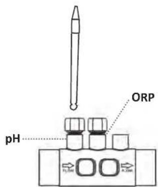
2.3 I Installing the sensors (pH & pH/ORP, depending on model) 12
2.4 I Installing the pH pump (pH\& pH / ORP, depending on model) 13
2.5 | Installing the control box 15
2.6 | Connecting auxiliary devices 16

3 Preparing the pool 19
3.1 Balance the water 19
3.2 I Add salt 20

4 Use
4.1Userinterface 21
4.2I Routine use 23
4.3 I Settings that can be accessed in Configuration mode 24
4.4 I Calibrating the sensors (pH or pH/ORP models) 32

Remote control using Fluidra Connect and NN app
5.1 Wiring the chlorinator to Fluidra Connect power center 34
5.2 I Managing the chlorinator remotely with NN app 35

6 Maintenance 36
6.1 Sensor maintenance 36
6.2 Inspecting and cleaning the electrodes 37
6.3 | Peristaltic pump maintenance 38
6.4I Winterising 39
6.5 | Preparing the pool for new season 39

Troubleshooting
7.1 I User alerts 40
7.2 I Effects of the stabilising agent on chlorine and ORP 41
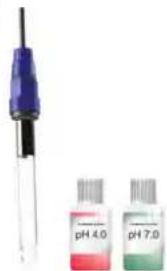
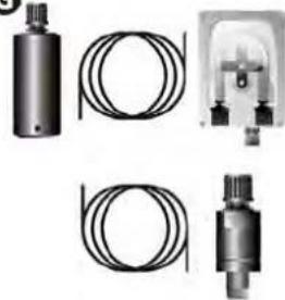
1.1 | Contents
A
B
C
D
E
F
G
| eXPERT eXPERT pH | eXPERT pH/ORP | ||
| A | Control box | ✔ | ✔ |
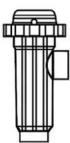
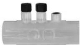
| B | Electrolysis cell | ✔ | ✔ |
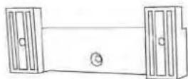
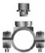
| C | Wall-mounting bracket kit | ✔ | ✔ |
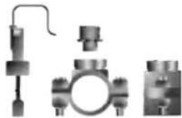
| D | Flow switch with installation kit | ✔ | ✔ |
| E | Sensor holder kit | ✔ | |
| F | pH sensor (blue) + pH 7 and pH 4 buffer solutions | ✔ | |
| G | PH pump kit: peristaltic pump, filter, injector, 2 metre suction (transparent 6x4 PVC) and injection (white 6x4 PE) pipes | ✔ | |
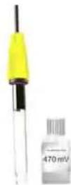
| H | ORP sensor (yellow, with gold tip) + ORP buffer solution 470 mV | ✔ | |

Included
1.2 | Technical specifications
| eXPERT | 7 12 21 30 40 | ||||
| Operating water temperature 5 - 40°C | |||||
| Volume of treated water (m3) (temperate climate, 8h/day filtration) | 30 50 100 | 140 180 | |||
| Nominal chlorine production 7 g/h 12 g/h 21 g/h 30 g/h 40 g/h | |||||
| Nominal output current | 3.5 A | 6 A | 3.5 A | 6 A | 6.5 A |
| Fuse (5x20 mm) | 1 A T | 2 A T 2 A T 3.15 A T 4 A T | |||
| Recommended salt level (g/L) | 5 | 5 | 4 | 4 4 | |
| Min-max: 4-10 | |||||
| Power supply voltage | 230V 50-60 Hz | ||||
| Electrical power | 46 W | 92 W | 92 W | 184 W | 207 W |
| Protection rating | IPX5 | ||||
| Minimum flow rate required through the cell (m3/h) | 3 | 3 | 5 | 6 8 | |
| Maximum allowable pressure in the cell | 1 bar | ||||
| Number of electrode plates | 3 | 5 | 7 | 11 | 13 |
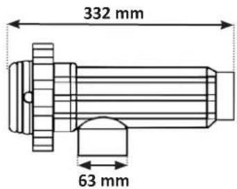
| Cell connection | Ø63 mm (use Ø50mm PVC reducers for 50mm pipe) | ||||
| Sensor type | Combined, glass body Ø12 mm | ||||
| pH measurement range | 0.0 - 9.9 pH | ||||
| pH measurement accuracy | 0.01 | ||||
| Sensor tolerance | 0-40°C, water speed ≤ 2 m/s | ||||
| pH sensor calibration | Semi-automatic in 2 points (pH 4 and pH 7) | ||||
| ORP measurement scale | 0 - 999 mV | ||||
| ORP measurement accuracy | 1 mV | ||||
| ORP sensor calibration | Semi-automatic at 1 point (470 mV) | ||||
| Maximum counter pressure (injection point) | 1.5 bar | ||||
| Peristaltic pump flow rate (pH) | 1.5 L/h | ||||
| Length of box-cell cable | 1.5 m | ||||
| Packaged net weight (kg) | 9 11 13 15 17 | ||||
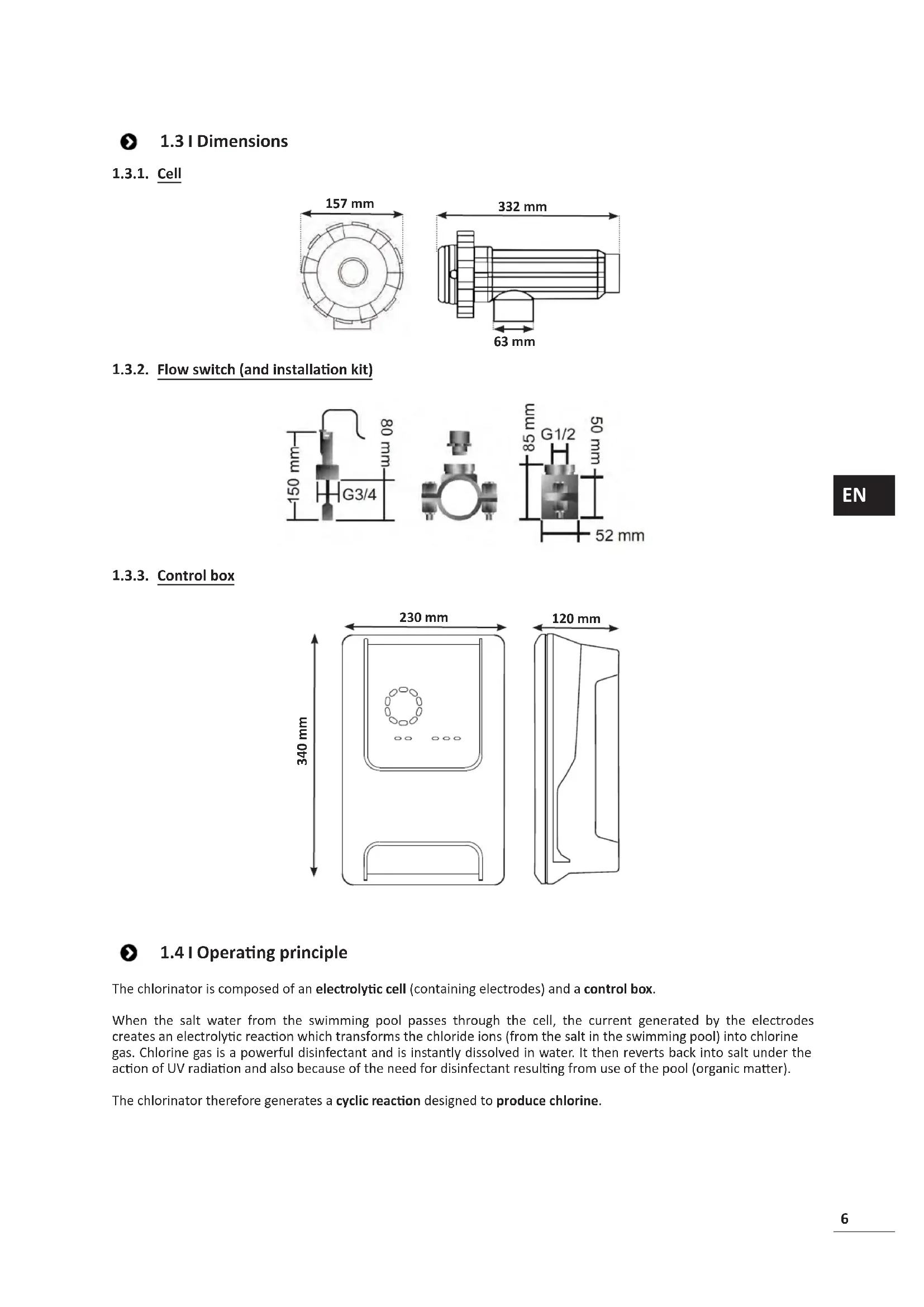
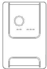
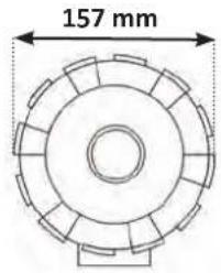
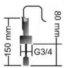
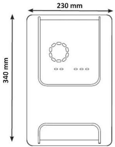
1.3 | Dimensions
1.3.1. Cell
1.3.2. Flow switch (and installation kit)
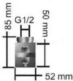
1.3.3. Control box
1.4 | Operating principle
The chlorinator is composed of an electrolytic cell (containing electrodes) and a control box.
When the salt water from the swimming pool passes through the cell, the current generated by the electrodes creates an electrolytic reaction which transforms the chloride ions (from the salt in the swimming pool) into chlorine gas. Chlorine gas is a powerful disinfectant and is instantly dissolved in water. It then reverts back into salt under the action of UV radiation and also because of the need for disinfectant resulting from use of the pool (organic matter).
The chlorinator therefore generates a cyclic reaction designed to produce chlorine.

2 Installing the salt water chlorinator
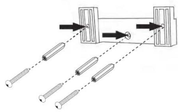
2.1 I Installing the electrolytic cell

- The cell must always be the last element placed on the pool return pipe (see § 2.1.1. Installing the cell and the sensor holder (depending on model)).
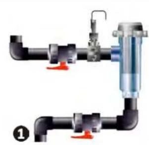
- It is always recommended to install the cell on a by-pass. This assembly is mandatory if the flow is in excess of 18m^3/ hour to avoid head loss. A flow regulation valve must be included.
- When the cell is installed on a by-pass, fit a check valve downstream from the cell instead of a manual valve, to avoid any risk of incorrect configuration and poor circulation inside the cell.
2.1.1. Installing the cell and the sensor holder (depending on model)
- The cell must be installed on the piping after the filtration system, after any measurement sensors, and after any heating system.
- The cell's installation must allow easy access to the installed electrodes.
- Two valves must be installed for isolating the cell from the rest of the installation, so that maintenance tasks can be performed without emptying the pool.
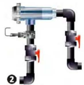
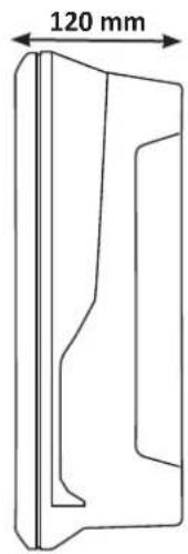
Installing the chlorinator on a by-pass (recommended) Direct installation
A Control box
B Cell
Flow switch
D Filter
(*depending on model)
Electric terminal block
Sensor holder + pH sensor and/or ORP sensor
G pH pump
H Container of pH-minus*
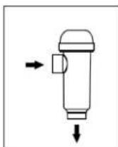
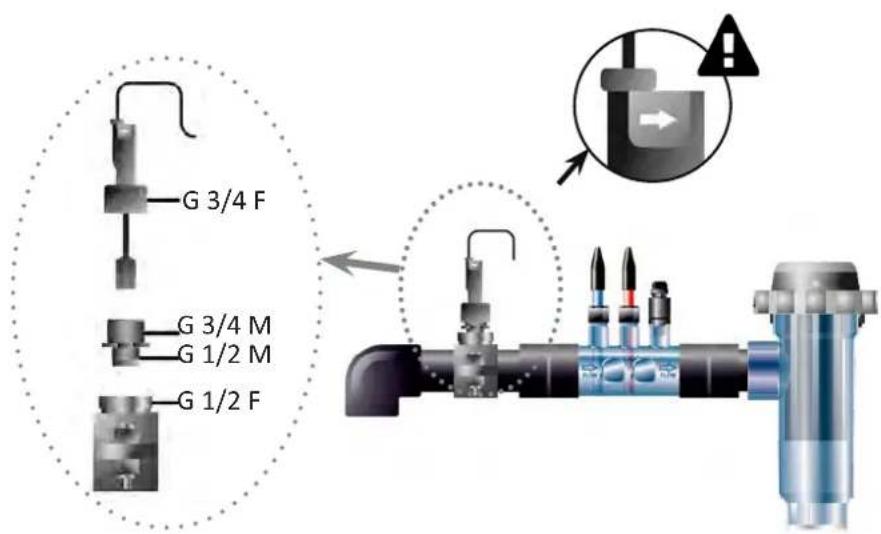
Direct installation only possible if the flow rate is going up.
- Respect the water flow direction indicated on the cell.
- The circulation system must guarantee the minimum required flow (see § 1.2 | Technical specifications").
- For 50 mm pipes,use glue-on PVC adapters of the corresponding diameter.
- Connect the cell power cord following the wire colour codes (red, yellow, and orange connectors) and then refit the protective cap (see § 2.1.3. Connecting the cell to the control box).
2.1.2. Connecting the cell and the sensor holder

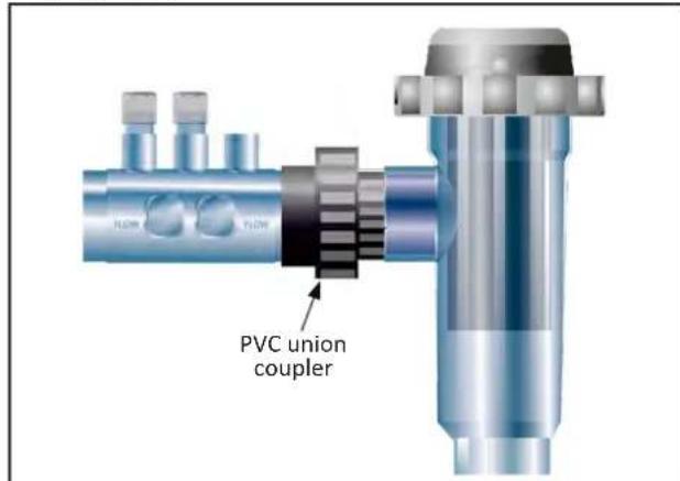
- Do not glue sensor holder and cell directly together : use a PVC union coupler (not included) between sensor holder and cell.

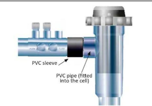
It is also possible to use a 6-to-8 cm PVC tube, 63cm with one beveled end (the one to glue to the cell inlet) and a PVC sleeve (to glue between the PVC tube and the sensor holder).
For connecting the cell and the sensor holder :
- Degrease the sensor holder, the cell inlet and the PVC union with PVC cleaner (not supplied).
- Glue the sensor holder and the female union and fit them into each other as far as it will go. Remove any excess glue with a damp cloth.
- Glue the cell inlet and the male union and fit them into each other as far as it will go. Remove any excess glue with a damp cloth.
Connecting the cell and the sensor holder
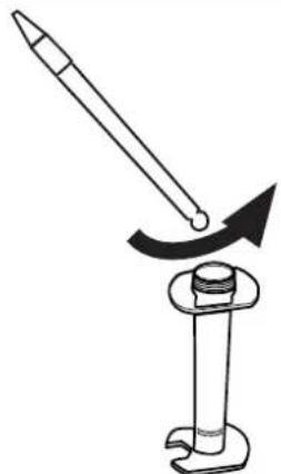
2.1.3. Connecting the cell to the control box
- Open the cell protective cap by turning it anti-clockwise.
- Identify the function of each wire (red, yellow, orange) in the power cable.
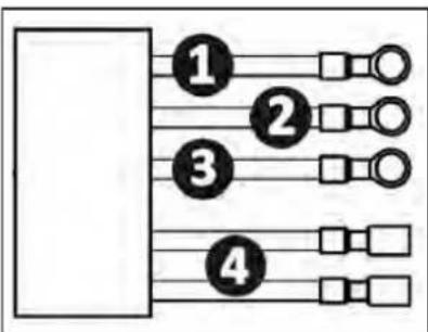
| Cable colour Function | |
| 1 | Red Electrolysis |
| 2 | Red Electrolysis |
| 3 | Yellow AUX / Conductivity |
| 4 | Orange Temperature |
- Identify the input points on the cell for each function, according to the appliance model:
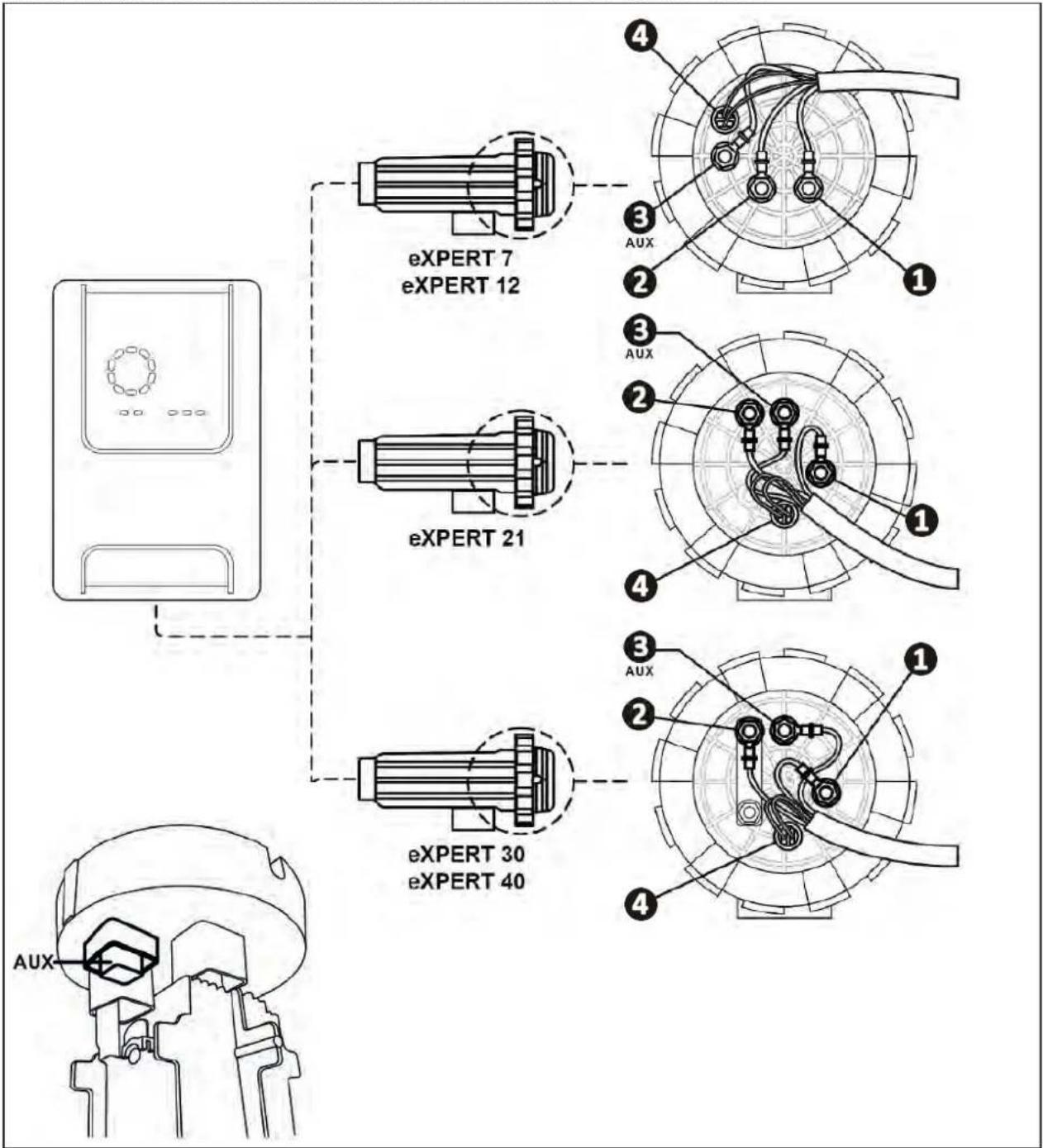
- Attach the connectors by successively installing the terminals, washers, and nuts (see following table).

- Carefully tighten the top nut by hand (risk of irreversible leakage).
| eXPERT 7 exPERT 12 | |
| eXPERT 21 | |
| eXPERT 30 exPERT 40 |
- Connect the cell to the control box, see§ "2.5 I Installing the control box".
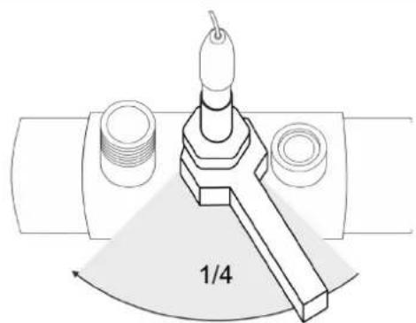
2.2 I Installing the flow switch

- Failure to comply with these instructions could lead to the destruction of the cell. The manufacturer cannot be liable in this case.
- The flow switch has a direction for installation (arrow indicated on it showing the flow direction for the water). Make sure that it is correctly placed on its fixture collar so that it stops the appliance's production when filtering is stopped.
-
The flow switch and its fixture collar (supplied) must be installed just in front of the cell and after a possible valve, in the flow section that supplies the cell.
-
Tighten the nuts by hand.
Installation of the flow switch and the installation kit
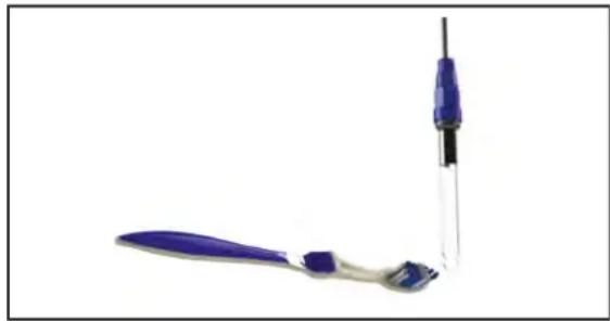
2.3 | Installing the sensors (pH & pH/ORP, depending on model)

- Never wipe the sensor using a cloth or paper tissue, as this may damage it.
-
A badly-installed sensor may give false readings and cause inappropriate operation of the appliance. Neither the manufacturer nor the appliance shall be liable in this event.
-
Carefully unscrew the protection tube from the sensor (1). Keep the protection tube for storing the sensor over winter.
- Rinse the end of the sensor with tap water and shake off excess water (2).
- Loosen the nut fixed to the sensor holder (3).
- Install the pH sensor and/or the ORP sensor (supplied) in the sensor holder so that the sensor located at the end of the holder is always submerged in the water flowing through the piping. Ensure that the cable is not tangled.

- To avoid damage, sensor end must be located in the center of the pipe, not further.
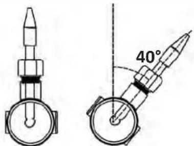
-
The sensor must always be installed vertically, or where necessary, at a maximum angle of 40^() .
-
Once the sensor is installed it can be connected to the BNC socket on the control box, see § "2.5.2. Connecting the control box".
- The sensor must then be calibrated, see § "4.4 | Calibrating the sensors (pH or pH/ORP models)".
1

2
3
4
5

2.4 I Installing the pH pump (pH & pH/ORP, depending on model)

- When handling chemical products, always use appropriate safety equipment (safety glasses, gloves, jacket and mask).


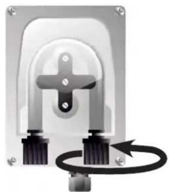
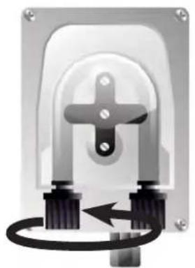
- The pH pump is a peristaltic pump that rotates in the clockwise direction: it sucks up acid (pH-minus) to inject into the pool.
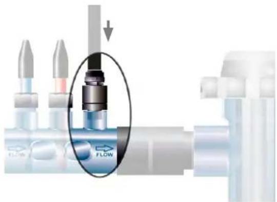
2.4.1. Installing the pH minus injection line
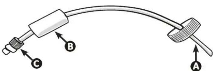
- Cut a suitable length of white hose from the coil (supplied) to connect the pH pump to the injection check valve.
- Unscrew the connector cap and attach the hose to the connector at the outlet of the pH pump, see figure①. Screw the cap in place.
- Attach the other end of the hose to the injection check valve, see figure 2.
1
2
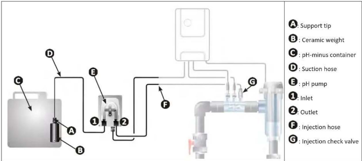
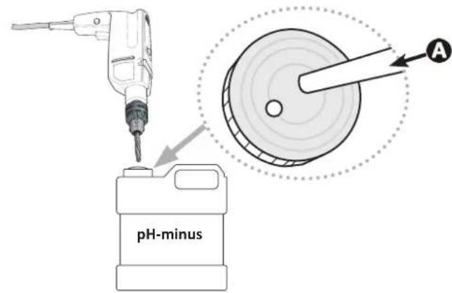
2.4.2. Installing the pH minus suction line
- Cut a suitable length of transparent hose from the coil (supplied) to connect the container of pH-minus to the pH pump.
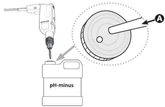
- Unscrew the connector cap and attach the hose to the connector at the inlet of the pH pump, see figure 1. Screw the cap in place.
- Drill two holes into the cap of the pH minus container, see figure 2:
- One hole suitable for the diameter of the hose A to aspirate the product.
- One smaller hole to prevent the container from becoming deformed during aspiration of the product.
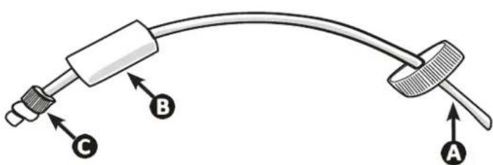
- Pass the free end of the suction hose (A) through the hole made in the cap (B) and put the ceramic weight provided (C) and the support tip on the hose, see figure.
- Ensure that all connections are correct and watertight before operating the appliance.

1
2
3

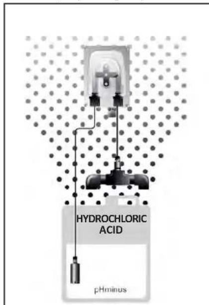
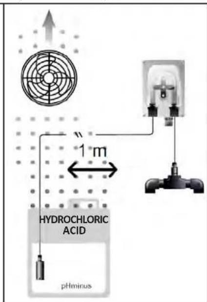
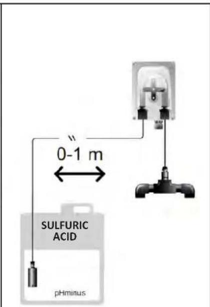
Do not place the pH-minus container directly beneath electrical equipment in the technical room to prevent risk of corrosion resulting from potential acidic vapours.
2.51 Installing the control box
2.5.1. Placement of the control box
- The control box must be installed in a dry ventilated technical room protected against frost, with no pool maintenance products or similar products stored nearby.
- The control box must be installed at a distance of at least 3.5m from the outside edge of the pool. Always comply with the installation codes and/or laws applicable at the place of installation.
- It must not be installed more than 1.6 metres from the cell (maximum cable length).
-
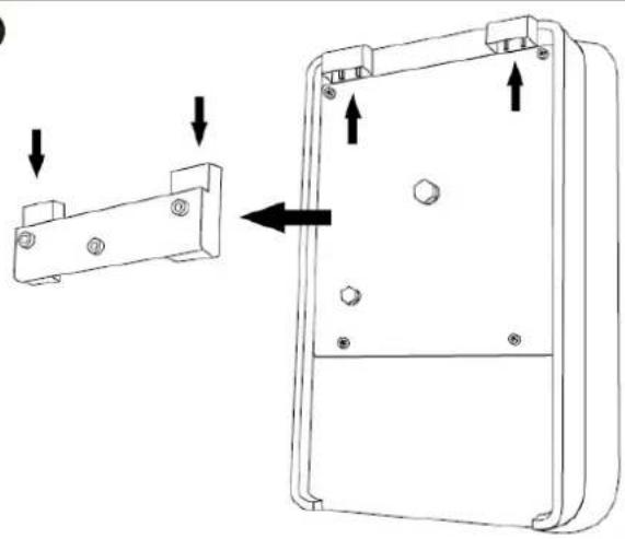
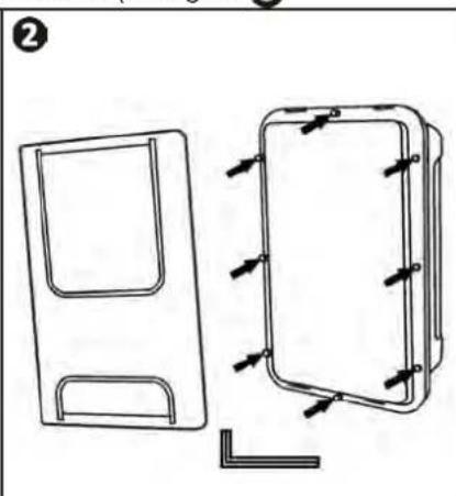
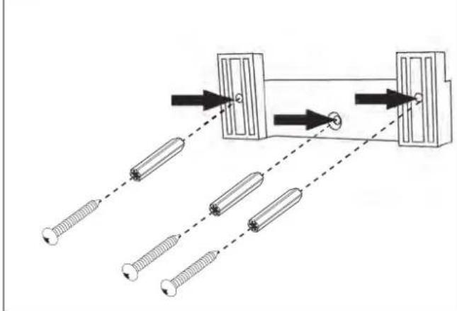
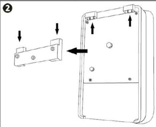
If the box is fixed to a post, a watertight panel must be fixed behind the control box (350x250 mm minimum):
-
Secure the mounting (provided) to the wall or to the watertight panel using screws or wall plugs (not provided) (figure 1).
-Clip the top of the control box into the mount (figure 2)
0
2
2.5.2. Connecting the control box

- Before beginning, disconnect all potential power supplies to the appliance.
-
Check that the cables used comply with the intended use and with the regulations in force.
-
Identify the connection point for each desired function at the bottom of the control box:
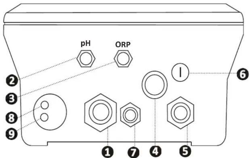
| 1 | Electrolysis cell |
| 2 | pH sensor (BNC connector)* |
| 3 | ORP sensor (BNC connector)* |
| 4 | ON/OFF switch |
| 5 | Power supply (230V, 50-60Hz) controlled by filter pump relay (ON when pump is running) |
| 6 | Fuse |
| 7 | pH pump* |
| 8 | Available space for Modbus cable if controlled with Fluidra Connect automation (NN app) |
| 9 | Flow switch |
(*depending on model)
2.6 I Connecting auxiliary devices
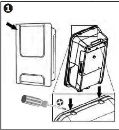
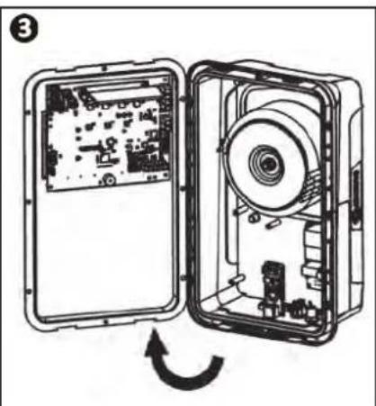
2.6.1. Open the control box
- Use a screwdriver to pry open the clips at the top of the front cover to dislodge it (see figure 1).
- Using a No. 3 Allen key, unscrew the 8 screws that secure the screen (see figure 2)
- Open the box and carefully position the screen (see figure 3)
2.6.2. Detail of connections
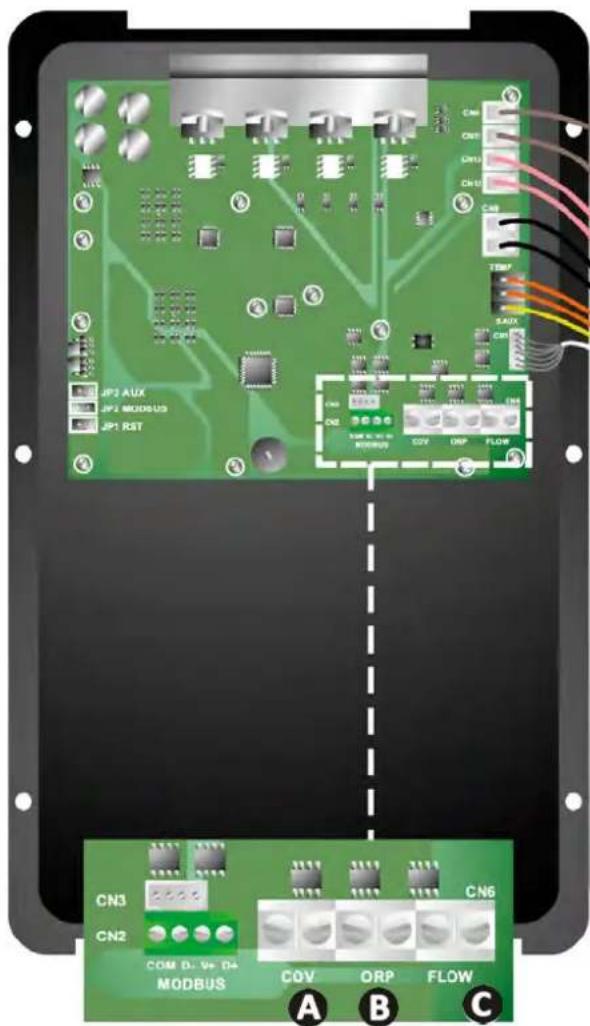
| Contact closed (ON) Contact open (OFF) Activate the function | |||
| A Pool Cover | Pool cover closed: reduced production (10% to 90%) | Pool cover open : 100% production | See§ “4.3.7. “Cover”: Connecting a pool cover" |
| B Slave mode | External chlorination controller connected (ORP or PPM) | No external chlorination controller (ORP or PPM) or automatic ORP regulation (pH/ ORP model) | See § "4.3.12. “CI EXT”: Slave mode" |
| C Flow switch* | Flow switch detected | No flow detected: Alarm flow | See § "4.3.5. “Flow”: Activating the flow switch" |
| D pH pump | 230 V supply when pH correction is needed (depending on model) | See § "2.6.3. pH pump connection (for pH - PH/ORP models)" | |
(*Flow switch comes already wired from the factory)
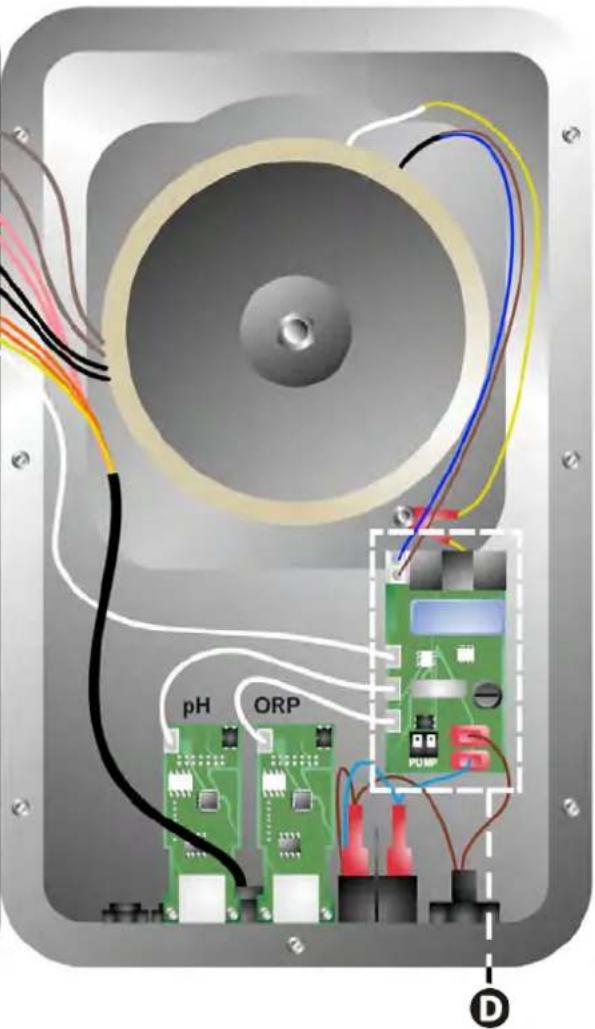
2.6.3. pH pump connection (for pH - PH/ORP models)

- Above 500mA , the pH pump connection must be protected by a circuit breaker with a suitable residual current protection device and controlled using a relay.


pH pump fuse: 5 × 20 T 500 mA/250V

pH pump (included)

pH pump >500mA (not included)

230V relay


Preparing the pool
3.1 I Balance the water
The water used must originate from a supply network compliant with Directive 98/83/EC on the quality of water intended for human consumption. In order for the water to be treated optimally, carry out measurements and adjust the values in accordance with the following recommendations:
Seasonal analyses in "preparation for re-use"
- Stabiliser (cyanuric acid) (<30 mg/L, ppm): the stabiliser protects chlorine from the destructive power of the sun's U.V. rays. Excessive stabiliser can block the disinfecting power of chlorine and turn the water turbid.
- Metals (Cu, Fe, Mn) ( ± 0 mg / L , ppm): metals damage the metallic parts of the pool (corrosion phenomenon) or can cause permanent stains.
Monthly analyses
- TH (150 - 300 mg/L CaCO₃, ppm): the TH measures the water hardness (quantity of calcium carbonate), and this value can vary significantly depending on the geographical region concerned.
- TA (80 -150 mg/L CaCO₃, ppm): the TA measures the water alkalinity, and this value allows the pH to be stabilised. It is important that the TA is adjusted before the pH.
Weekly analyses
- pH (7.0 - 7.4): the pH measures the acidity or alkalinity of the water. A pH in the range 7.0 to 7.4 helps to preserve the pool equipment and maintain effective disinfection. Taylor's balance method, as shown below, is used to adjust the pH value:
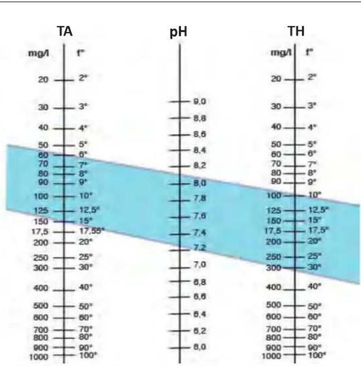
A: Mark the value of the TH after adjustment.
B:Mark the value of the TA after adjustment.
Draw a line between the TH value and the TA value to determine the pH value to be adjusted.
Taylor's balance
- Free chlorine (0.5 - 2 mg/L or ppm): this quantity of free chlorine makes the water both disinfected and disinfecting.

Contact your retailer to determine the type of corrector product or automatic control appliance to be used to adjust the values.

3.2 I Add salt
Every appliance must be operated with a minimum recommended salt level, see § "1.2 | Technical specifications".

In order for the chlorinator appliance to operate properly, and to protect the equipment, we recommend using salt (sodium chloride) as per standard EN 16401.
3.2.1. Determining the quantity of salt to be used when installing the appliance
Example:
A. Appliance operating with 4kg of salt per ^3 of water (= 4g / L or 4000 ppm).
B. Appliance operating with 5kg of salt per ^3 of water (= 5g / L or 5000 ppm).
- 50m^3 pool.
The formula:
A. 50 ~m^3 × 4 ~kg of salt m^3 = 200 ~kg of salt to be added to the water
B. 50 ~m^3 × 5 ~kg of salt m^3 = 250 ~kg of salt to be added to the water
3.2.2. Routine analyses
Check the salt level quarterly and readjust the quantity of salt present where necessary.
= = > Method for adding salt to the water
- Start the filter pump to cause the water in the pool to circulate.
- If the appliance has already been installed, switch it off.
- Move around the perimeter of the pool while pouring the required quantity of salt into the water to help dissolution. Add the salt in stages. It is easier to add salt to make up for an insufficient quantity that to dilute the salt present to make up for an excessive quantity.
- Operate the filter pump for 24 hours.
- After 24 hours have passed, check that the salinity level in the pool is correct, i.e. 4g / l itre or 5g / l itre (in the examples cited).
- If the salt level is correct and the appliance has already been installed, switch it on then adjust the desired level of chlorine production, see § 4.2.1. Adjusting chlorine production".

Do not add salt directly in the skimmer(s).
The appliance must only be switched on when the salt has completely dissolved in the pool.
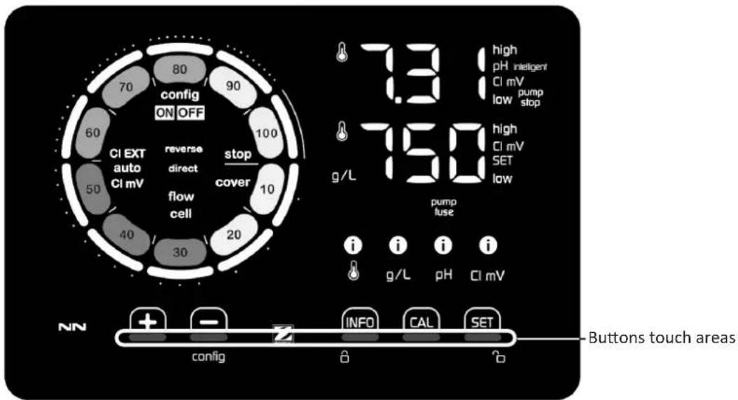
4.1 I User interface
4.1.1. User interface presentation
| BROWSING BUTTONS | |
| INFO | - Display the values for water temperature, salt concentration, pH & ORP values and setpoints (depending on model) and Boost mode management. - Browse and exit the Configuration menu |
| CAL | - Calibrate |
| SET | - Configure values and confirm |
| config | - Reduce production or a selected value - Access to the Configuration menu (hold 5 seconds with chlorination set to 0%) |
| + | - Increase production or a selected value |
| @ | - Slide from left to right to unlock, see § "4.1.2. Unlocking the screen" |
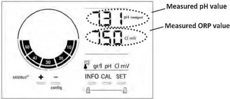
| INDICATORS | |
| Actual chlorine production | |
| Chlorine production setpoint | |
| config | Configuration mode activated |
| cover | "Pool cover" mode activated |
| auto Cl mV | Automatic ORP regulation activated |
| pH redigert | pH display (depending on model): "intelligent" appears if mode is activated |
| CI EXT | Slave mode activated |
| reverse direct | Current cell polarity (direct or reverse) |
| g/L | Salt concentration display |
| Water temperature display | |
| CI mV | ORP mV display (shows chlorination efficiency) |
| SET | Setpoint display |
| stop | Chlorination is off (setpoint = 0%) |
| ALARMS | |
| 1g/L | Measured temperature too high or too low (non-blocking) |
| Measured salt concentration too high or too low (non-blocking) | |
| 1pH | Measured pH too high or too low (non-blocking) |
| 1Cl mV | Measured ORP value too high or too low (non-blocking) |
| high | Values too high |
| low | Values too low |
| pump stop | pH pump stopped |
| pump fuse | pH pump fuse blown |
| cell | Cell damaged or calcified |
| flow cell | Water flow problem |
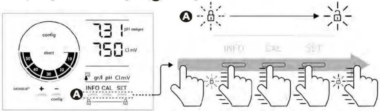
4.1.2. Unlocking the screen
After a while whitout any use, chlorinator user interface goes into standby display to save energy (depending on the setting in the configuration menu). To wake it up, screen needs to be unlocked :
- Slide your finger across the unlocking zone (A) to the edge of the screen.

4.2I Routine use
4.2.1. Adjusting chlorine production
Chlorine production can be manually adjusted between 0 and 100% in intervals of 10% , by using + or - : the chlorine production setpoint indicator is adjusted (in the following example, for production at 70% ).
The setpoint value remains valid until next modified.
4.2.2. Displaying values and configuring setpoints
The pH and ORP values are automatically displayed on the home screen. Example with pH setpoint adjustment below (same logic for ORP setpoint).
To access all values and setpoints, press

- Press once to access the temperature value and setpoint,
- Twice to access the salt concentration value and setpoint,
- Three times to access the pH value and setpoint.
- Four times to access the ORP value and setpoint.
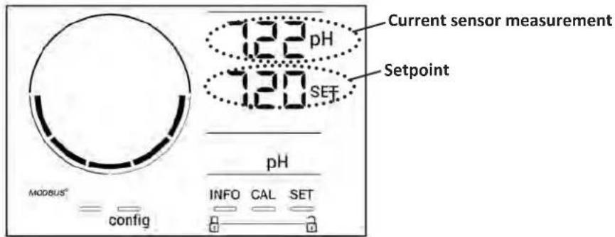
The measured value appears at the top, the setpoint underneath (indicated by the SET).
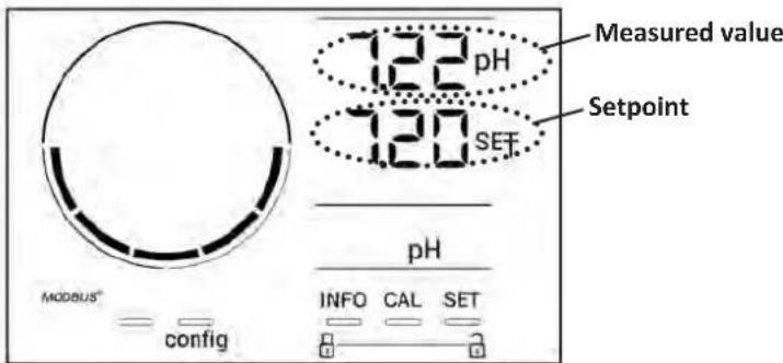
Example with pH setpoint adjustment (same logic for ORP setpoint)
4.2.3. "Boost" mode
In some cases, the pool may require a higher than normal chlorine level, for example during times of high use, bad weather or at the start of the pool season. "Boost" mode is used to quickly increase the chlorine level. It operates for 24 consecutive hours at a 100% production rate.
When the filtration pump is connected to the appliance, the chlorination and filtration timers are temporarily ignored throughout the duration of the "Boost" mode. Once deactivated, the appliance and the filter pump resume the programmed operations.
To activate the "Boost" mode:
- Press five times "OOST OFF" is displayed on the screen.
- Press 551 activate the mode: "OFF" flashes.
Press : "flashes.
Press confirm.
Press #FO exit.

- When "Boost" mode is active, the blue circle representing actual chlorination will flash and spin.
- "Boost" mode can be stopped at any time by applying the procedure above.
4.3 I Settings that can be accessed in Configuration mode
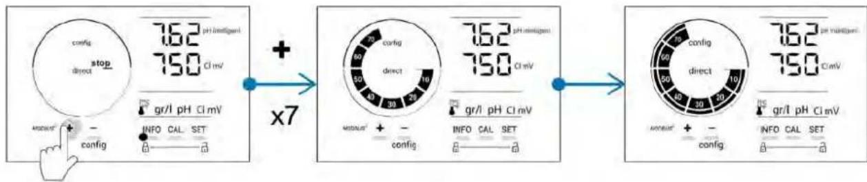
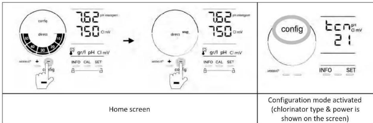
4.3.1. Accessing Configuration mode
From the home screen, press reduce chlorine production to 0% .
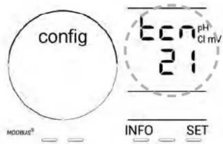
Press 5 seconds. The "Config" icon appears.
| Number of presses | Screen display Function Additional information | ||
| 0 | bcn | • Shows the appliance model • Displaying and resetting the number of operating hours of the cell or the pH pump | • See § «4.3.2. Appliance information» • See § «4.3.3. Displaying and resetting the number of operating hours of the cell or the pH pump» |
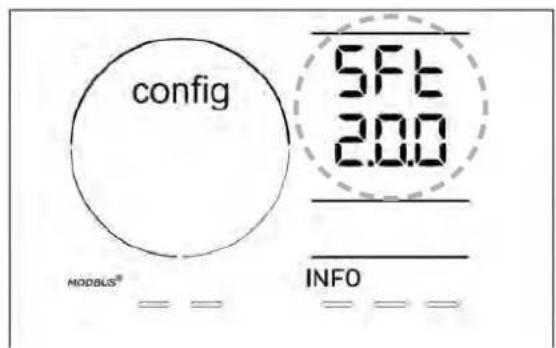
| 1 | SFE | Shows the software version in use • See § «4.3.2. Appliance information» | |
| 2 reverse direct Polarity reversal cycles adjustment | See § “4.3.4. “Reverse direct”: Reversal adjustment for cell cleaning” | ||
| 3 flow | Activation of the flow switch | See § “4.3.5. “Flow”: Activating the flow switch” | |
| 4 flow | cell Activation of the gas sensor | See § “4.3.6. “Flow cell”: Activating the gas sensor” | |
| 5 | cover | Activation of "Pool cover" mode | § “4.3.7. “Cover”: Connecting a pool cover” |
| 6 | pH intelligent | Activation of "Intelligent pH" mode | § “4.3.8. “Intelligent pH” mode” |
| 7 | in i pH | Activation of the “Initialisation” mode for pH regulation | § “4.3.9. “Ini pH”: Initialisation of pH regulation” |
| 8 | pump stop | Setting the pH pump over feed alarm triggering | § “4.3.10. “Pump stop”: pH pump stop over feed alarm (pH - PH/ORP models)” |
| 9 | auto Cl mV | Activation of the automatic ORP regulation | § “4.3.11. “Auto Cl mV”: Automatic ORP regulation (pH/ORP models)” |
| 10 | Cl EXT | Activation of Slave mode | § “4.3.12. “Cl EXT”: Slave mode” |
| 11 | i g/L | Setting the “Temperature” alarm triggering | § “4.3.10. “Pump stop”: pH pump stop over feed alarm (pH - PH/ORP models)” |
| 12 | g/L | Setting the “Salinity” alarm triggering | § “4.3.14. Setting the “Salinity” alarm triggering g/L” |
| 13 | d IS ECO | Activation of the user interface power saving mode | § “4.3.15. User interface energy saving mode” |
| 14 | bio | Activation of “Bio pool” mode for natural pools | § “4.3.16. “Bio”: “Bio pool” mode for natural pools” |
| Settings | |||
| N/A | N/A | Calibrating the temperature | See § “4.3.17. Calibrating the temperature” |
| N/A | N/A | Calibrating the salt concentration | See § “4.3.18. Calibrating the salt concentration” |
4.3.2. Appliance information
Show the appliance model Show the current software version

The appliance model is displayed on the screen (platform version and g/h power).

seconds then press . The
INFO
ware version is displayed on the screen.
4.3.3. Displaying and resetting the number of operating hours of the cell or the pH pump
- Press 5 seconds to see the "Appliance model" display.
- Press once on SET to view the number of hours the cell has been in use ("Config Cell" is displayed) or press 3 times on SET view the number of hours the pH pump has been in use ("Config" is displayed).
- The "h" value corresponds to the number of hours the cell has been in use since the last reset. Press twice on to reset the value.
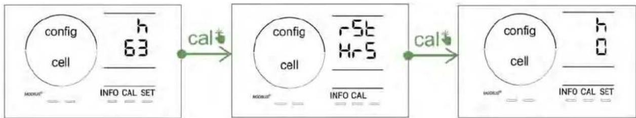
- Press set to switch to the "H" value: this corresponds to the total number of operating hours and cannot be reset.
Press 567exit.
4.3.4. "Reverse direct": Reversal adjustment for cell cleaning
The polarity reversal principle eliminates scaling that has deposited on the electrodes by reversing the electrical power at a specified time.
- The hardness of the water varies depending on the geographical region concerned (water hardness = TH).
- In order to protect the electrodes from scale build-up (which reduces the efficacy of the electrolysis reaction), the polarity reversal time can be adjusted.
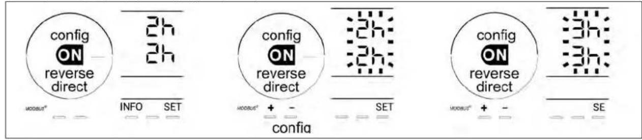
By default, the cycle is reversed every 2 hours. You may increase polarity reversal time to 3, 4 or 7h if water hardness is below 200 ppm (20°f). To set this duration:
- In the Configuration/Reverse Direct mode, press SET to change the duration of polarity reversal. The displayed duration flashes.
- Press to choose between 2h, 3h, 4h or 7h (or "tSt" test mode).
- Press SET onfirm the duration.
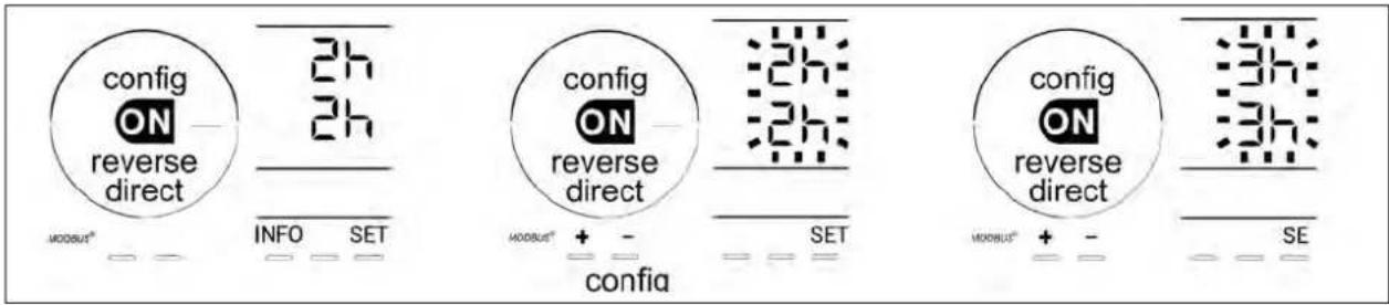

At the time of reversal, chlorination is stopped for a few minutes. No message is displayed on the screen. Normal operation resumes after reversal is complete.
4.3.5. "Flow": Activating the flow switch
This mode is activated by default. To deactivate the use of the flow switch:
From the Configuration/Flow menu, press SET:"OFF" flashes.
- Press to switch to "ON".
- Press SET confirm.
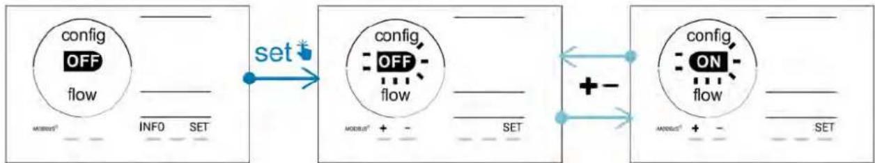

Deactivating the use of the flow switch is not recommended as it is a safety feature.
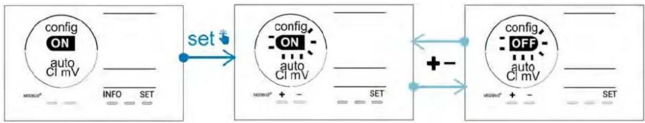
4.3.6. "Flow cell": Activating the gas sensor
This mode is activated by default. To deactivate the use of the gas sensor:
From the Configuration/Flow cell menu, press SET: "ON" flashes.
Press to switch to "OFF".
Press SET confirm.
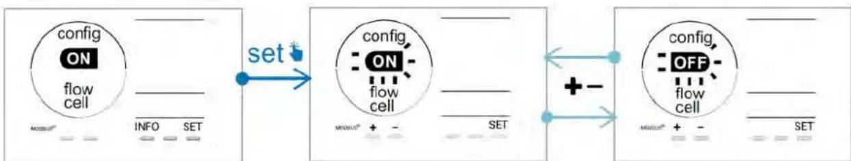

Deactivating the use of the gas sensor is not recommended as it is a safety feature.
4.3.7. "Cover": Connecting a pool cover
If the pool is equipped with a compatible electric cover, it can be connected to the appliance in order to automatically reduce chlorination when it is closed: this is the "Cover" mode. It is then automatically activated when the pool cover is closed, and chlorination resumes at the level determined by the programming on opening the compatible electric pool cover.

Check that the cover is compatible and is connected to the appliance on the low-voltage circuit, see § "2.61 Connecting auxiliary devices".
This mode is deactivated by default. To activate it and configure the production:
- From the Configuration/Cover mode, press SET then to activate or configure the desired percentage of production (configurable between 10% and 90%).
Press SETonfirm.
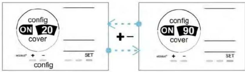

Recommendations for use:
- Adjust the production percentage to between 10% and 30% .
- You may let ORP regulation manage chlorination instead of pool cover mode if water stay warm when pool cover is closed.
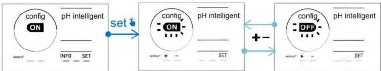
4.3.8. "Intelligent pH" mode
The "Intelligent pH" mode is used to adjust the pH more precisely: it reduces production as the setpoint is approached, thus reducing wider fluctuations in pH levels.
This mode is activated by default. To deactivate it:
From the Configuration/Intelligent pH mode, press SET: "ON" flashes.
- Press + reactivate it ("OFF").
Press SET onfirm.
4.3.9. "Ini pH": Initialisation of pH regulation
This mode allows the pH measurement to stabilise over a certain time at each start-up, before starting to dose (if necessary). The initialisation time can be set to 0, 1, 2 or 4 minutes.
This mode is deactivated by default. To activate it:
From the Configuration/Ini pH mode, press SET:"OFF" flashes.
- Press to activate ("ON") and to configure the initialisation time.
Press SET onfirm.

- It is advised to enable this feature and set it to "1 min" to prevent unwanted pH corrective product injection upon each filter pump startup.
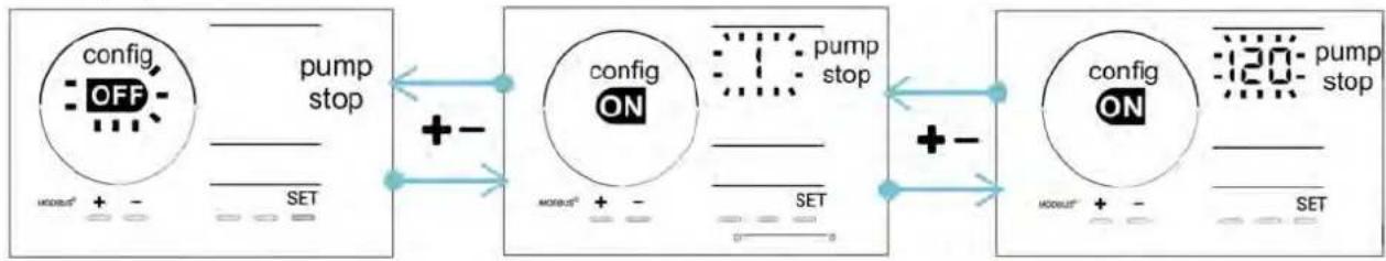
4.3.10. "Pump stop": pH pump stop over feed alarm (pH - PH/ORP models)
The pH pump stops rotating if the pH setpoint has not been reached after a given time, resulting in the display of an alarm. By default, this programmed safety time is 60 minutes. To adjust it (minimum value: 1 min - maximum value: 120 min):
From the Configuration/Pump stop mode, press SET: "OFF" flashes
- Press switch to "ON". The injection time flashes.
Press to this value.
Press confirm.
4.3.11. "Auto Cl mV": Automatic ORP regulation (pH/ORP models)
This mode is activated by default on pH/ORP models only. Production stops when the setpoint is passed. To deactivate the automatic mode:
From the Configuration/Auto Cl mV mode, press SET:"ON" flashes.
- Press Activate it ("OFF").
Press confirm.
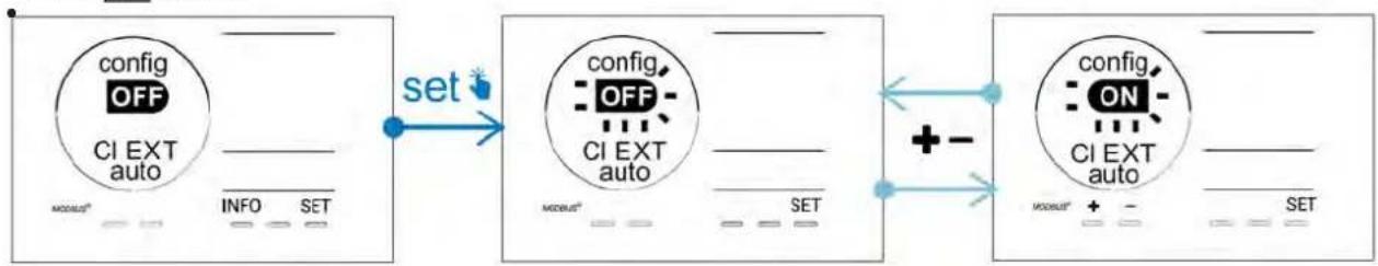
4.3.12. "CI EXT": Slave mode

- Ensure that these appliances are properly connected to the power supply in accordance with the regulations in force and are protected by a circuit breaker (filtration unit).
Slave mode transfers control over the chlorination function to an external controller (ORP or ppm control). Once the external controller is correctly connected to the connection point (see § 2.6.2. Detail of connections), activate the Slave mode:
From the Configuration/CI EXT auto mode, press SET:"OFF" flashes.
- Press + activate it ("ON").
Press confirm.
4.3.13. Setting the "Temperature" alarm triggering
When the measured temperature is outside the configured range, an alarm is displayed. The recorded default range is 5^ - 40^ . To adjust it:
From the Configuration/ mode, press SET: the minimum value (indicated by "LO") flashes.
- Press + or - to adjust this value (select 0 to deactivate the alarm).
- Press confirm: the maximum value (indicated by "HI") flashes.
Press to st this value.
- Press SET hfirm.
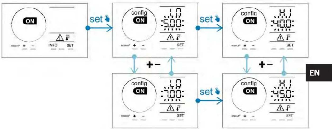
4.3.14. Setting the "Salinity" alarm triggering 1g / L
When the water's measured salt concentration is outside the configured range, an alarm g/L is displayed. The recorded default range is 2.5 g/L - 8 g/L). To adjust it:
From the Configuration/ 日 g/L mode, press SET: the minimum value (indicated by "LO") flashes.
- Press + or - to adjust this value (select 0.5 to deactivate the alarm).
- Press confirm: the maximum value (indicated by "HI") flashes.
Press to st this value.
Press SET hfirm.

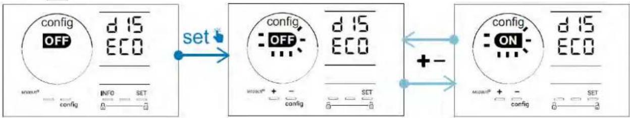
4.3.15. User interface energy saving mode
By default, the screen power saving mode is activated and an appliance which is unused goes into standby: an animated production indicator is displayed and the measured values are not visible. To deactivate this mode:
From the Configuration/D15 ECO mode, press SET: "OFF" flashes.
- Press switch to "ON".
Press SET confirm.
4.3.16. "Bio": "Bio pool" mode for natural pools
The "Bio" mode is used to modify the pH and ORP setpoints and the related high and low alarms (see the values in the table below) so they are best suited to natural pools.
| « Bio pool » mode | Threshold | Alarm High (HI) Low (LO) | |||
| pH | OFF (default) 7.0 | 7.8 > 8.5 < 6.5 | |||
| ON 6.5 8.5 | > 9.0 < 6.0 | ||||
| ORP (mV) | OFF (default) 600 | 850 > 855 < 600 | |||
| ON 300 850 | > 855 < 300 | ||||
By default, this mode is disabled; to activate it:
From the Configuration/bio mode, press set:"OFF" flashes.
- Press activate it ("ON").
Press set confirm.
4.3.17.Calibrating the temperature
From the home screen, press INFO access the temperature values (^*)
- Press CAL to enter the Calibration mode. The screen displays Standard
Press CAL select this mode. The value flashes.
- Press to change the value.
Press confirm.

Press SET at this step to switch between a temperature display in degrees Celsius (°C) and degrees Fahrenheit (°F).
4.3.18. Calibrating the salt concentration
From the home screen, press twice on INFO access the salinity values.
- Press CAL to enter Calibration mode. The screen displays Std ("Standard").
Press select this mode. The value flashes.
- Press to change the value.
Press confirm.
4.4 I Calibrating the sensors (pH or pH/ORP models)
4.4.1. Choosing the calibration mode
- The pH sensor and the ORP sensor can be calibrated in "Standard" mode
- The pH sensor can also be calibrated in "Fast" mode
| Std | F5t | r5t CAL |
| Standard mode (pH & ORP) Fast mode "Fast" (pH) Restart | ||
| Calibrate the sensor by removing it | Calibrate without removing the sensor | Restart calibration |
4.4.2. Calibrating the pH sensor in "Standard" mode
In "Standard" mode, the pH sensor is calibrated in 2 point calibration (pH 4 and pH 7); 2 point calibration is recommended for more accurate measurement.
- Switch off the pool's pump and close the necessary valves in order to isolate the cell and the sensors.
From the home screen, press INFO to access the pH values. - Press CAL to enter Calibration mode. The screen displays Standard .
Press select this mode. The screen displays - Remove the sensor.
- Rinse the tip of the sensor with tap water.
- Shake it to remove any residual water. Do not touch the glass bulb at the end of the pH sensor.
- Place the tip of the pH sensor in the pH 7 solution.
- Wait 15 seconds.
Press CONTINUE. The screen displays.
- Rinse the tip of the sensor with tap water.
- Shake it to remove any residual water. Do not touch the glass bulb at the end of the pH sensor.
- Place the tip of the pH sensor in the pH 4 solution.
- Wait 15 seconds.
- Replace the sensor back in its holder.
- Press. Calibration is complete.
- If necessary, adjust the setpoint (see § 4.4.4. Configuring the pH setpoint") or press to return to the home screen.
4.4.3. Calibrating the pH sensor in "Fast" mode
In "Fast" mode, the pH sensor is calibrated in 1 point calibration; 1 point calibration is possible if the pH 7 and pH 4 solutions provided are not available.
From the home screen, press INFOs to access the pH values.
- Press CAL to enter Calibration mode. The screen displays (Standard).
- Press screen displays ("Fast calibration mode").
- Press . CAL second displayed value flashes.
- Place a pH meter in the pool's water then modify this second value with + or - so that it matches the value displayed by the pH meter.
- Press tCAL onfirm. The current sensor measurement has been replaced.
If necessary, adjust the setpoint (see § 4.4.4. Configuring the pH setpoint") or press INFO to return to the home screen.
4.4.4. Configuring the pH setpoint
The pH setpoint configuration determines the time when acid is added to the system to reduce the water's pH. The default value of the pH setpoint is 7.2.
To determine the value of the setpoint to be configured, refer to Taylor's balance, see § "3.1 | Balance the water".
Press e times to display the pH setpoint.
- Press setpoint value flashes.
- Press + and to select the desired value. These values are increments of 0.1.
Press confirm.
Press 14-FGxit.
4.4.5. Calibrating the ORP sensor
- Switch off the pool's pump and close the necessary valves in order to isolate the cell and the sensors.
From the home screen, press INFCmes to access the ORP values. - Press to enter Calibration mode. The screen displays Standard".
- Press select this mode. The screen displays
- Remove the sensor.
- Rinse the tip of the sensor with tap water.
- Shake it to remove any residual water. Do not touch the gold tip at the end of the ORP sensor.
- Place the tip of the ORP sensor in the ORP 470mV solution.
- Wait 15 seconds.
- Rinse the tip of the sensor with tap water.
- Replace the sensor back in its holder.
Press CAL libration is complete.
If necessary, adjust the setpoint (see § 4.4.6. Configuring the ORP setpoint") or press to return to the home screen.
4.4.6. Configuring the ORP setpoint
The ORP setpoint configuration determines the time at which chlorine is produced by the appliance. The level of free chlorine must be controlled at regular intervals after initial installation. The default value of the ORP setpoint is 700mV .
The value of the setpoint depends on the pool's environment, its affluence, and the amount of stabiliser present in the pool water.
From the home screen, press INFRmes to access the ORP values.
- Press set point value flashes.
- Press + and to select the desired value (recommended between 650 mV and 750 mV). These values are increments of 1.
Press set confirm.
Press INFDexit.

Remote control using Fluidra Connect and NN app
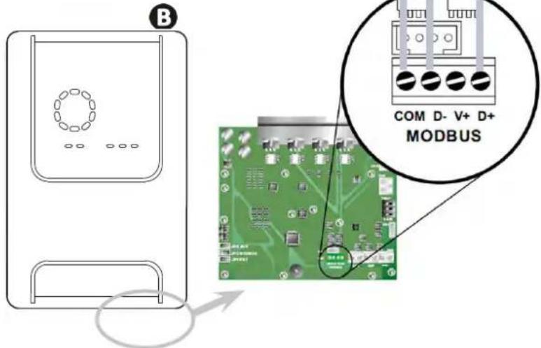
5.1 Wiring the chlorinator to Fluidra Connect power center
The chlorinator is a connectable device: information on the status of the swimming pool can be accessed at any moment (to check the dashboard, change a setting, etc.) from a smartphone or tablet via the Fluidra Connect NN app.
For this, the chlorinator must first be connected to a Connect & Go automation power center, following the connection method shown below.
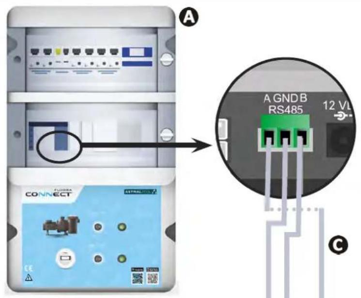
Connect & Go automation unit
Chlorinator
Connections:
| AD+ | BLUE | |
| GND | COM BROWN | |
| BD- | WHITE |

- It's strongly advised to use a specific RS485 cable to wire the chlorinator to the Connect & Go power center. If not available, an Ethernet cable can be used (RJ45 connectors cannot be used).
- The Fluidra Connect NN app also provides the possibility to locate professionals who can remotely check the swimming pool, access the measurement history, and display errors through a Fluidra Connect service platform.

5.2 I Managing the chlorinator remotely with NN app

Before you install the app, you must:
- Use a Wi-Fi-enabled smartphone or tablet,
- Use a Wi-Fi network with a reasonably strong signal when connecting to the chlorinator.
-
Have your home Wi-Fi network password at the ready.
-
Download the Fluidra Connect NN app from the App Store or Google Play Store.
- Connect to your account or register to create an account (first-time use).
- Access your pool settings or adjust setpoints remotely.
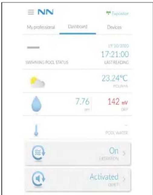
Access the pool settings from the " Dashboard" tab
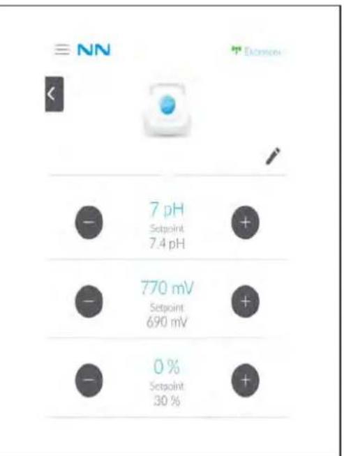
Adjust the setpoints from the "Devices" tab

6 Maintenance
6.1 Sensor maintenance
The sensors must be cleaned every 2 months.
- Stop the filter pump.
- Close all valves.
- Remove the sensor and the sensor holder.
- Rinse the sensor in tap water for 1 minute.
- Shake it to remove any residual water.

To prevent damage to the active part, do not rub and do not dry with a cloth.
- Brush the junctions and the metal part (Gold) for the ORP sensor using a toothbrush for 1 minute.
- Prepare a solution of diluted hydrochloric acid by pouring 1mL (10 drops) of commercially-available hydrochloric acid (HCl 37% into 50~mL of tap water (1/2 glass of water).

- Hydrochloric acid is a hazardous chemical that may cause burns, lesions and irritations. Handle with care and use protective equipment (gloves, safety glasses, overalls). Refer to the product's MSDS for more information.
Always pour the acid into the water. -
Once cleaning is complete, dispose of the solution according to the standard in force in the country of use.
-
Wash the sensor in the diluted hydrochloric acid solution for 2 minutes.
- Rinse the sensor in clean water under the tap for 1 minute.
- Shake it to remove any residual water.
- Then calibrate the sensor, see § "4.4 I Calibrating the sensors (pH or pH/ORP models)".
- Replace the sensor holder and the sensor.
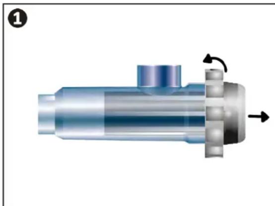
6.2 I Inspecting and cleaning the electrodes

The appliance is equipped with a smart polarity inversion system designed to prevent the electrode plates from scaling. The polarity reversal time can be modified, see § "4.3.4." "Reverse direct": Reversal adjustment for cell cleaning". However cleaning may be required in regions where the water is very hard.
- Turn off the appliance and the filtration system, close the isolation valves, remove the protection cover and disconnect the cell power cable.
- Unscrew the tightening ring and remove the cell. The ring is crenelated thus allowing a lever to be used in the event of it jamming (see figure 1).
- Submerge the part containing the electrode plates in a suitable recipient containing a cleaning solution (see figure 2).
2
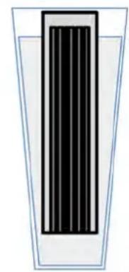
- Leave the cleaning solution to dissolve the scale deposit for about 10 minutes. Dispse of the cleaning solution at an approved waste recycling site. Never pour into the rainwater drainage system or into the sewers.
- Rinse the electrode using clean water and put it back on the cell fixture collar (there is an alignment foolproofer).
- Refit the tightening ring, reconnect the cell cable and refit the protective cover.
- Re-open the isolation valves and restart the filtering system and appliance.

If you are not using a commercially-available cleaning solution, you can make your own by carefully mixing 1 part hydrochloric acid with 10 parts water. (Caution: always pour the acid into the water and not the opposite and wear suitable protective equipment).
6.3 I Peristaltic pump maintenance
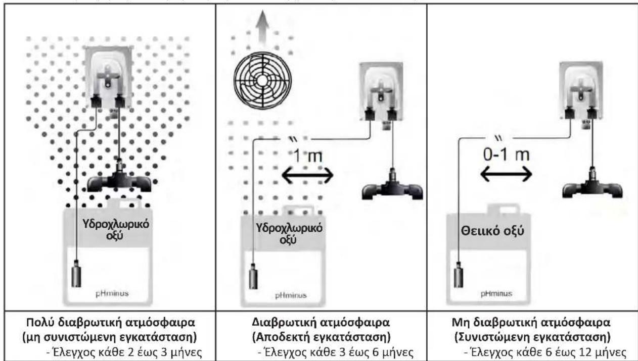
- To prevent the pump from operating when empty, check the level of the pH-Minus (acid) container every 2 to 12 months, depending on your installation (see table below).
Very corrosive atmosphere (installation not recommended) - Check every 2 to 3 months
Corrosive atmosphere (acceptable installation) - Check every 3 to 6 months
Non-corrosive atmosphere (recommended installation) - Check every 6 to 12 months
-
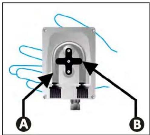
To check the correct operation of the pH pump:
-
Ensure the tube is in good condition and the connections are correctly sealed,
- Check that the tablet holder rotates correctly

6.4I Winterising

The appliance is fitted with a protection system limiting chlorine production in poor operating conditions such as cold water (winter) or low salt.
- Active winterising = filtering operational in winter: below 10^ it is preferable to switch off the appliance. Above this temperature you can leave it running.
- Passive winterising = lower water level and drained piping: switch off the appliance and leave the cell dry in place with any isolation valves open.
- Winterising the sensors = Keep the plastic sensor tube (which contains a storage solution) for re-use when winterising. The sensors must always be stored wet (never dry). They must be stored in the tube filled with a storage solution of 3mol / L KCl or at least in tap water.

6.5 | Preparing the pool for new season
Required actions:
- Adjust the water level (too much or too little).
- Check the water parameters: TA/TH/pH/Salinity/Chlorine/Stabiliser/Copper/Metals, and adjust the parameters to obtain a balanced, healthy pool, see § 3.1 Balance the water".
- Check the condition of the equipment (pump, filter, chlorinator, electrolytic cell).
- Inspect the sensors, then clean and recalibrate.
- As soon as the salt level reaches the required level (4,000 ppm or 5,000 ppm) and has completely dissolved in the water, restart the salt water chlorinator.
Q
Troubleshooting

-
Before you contact the retailer, carry out these few simple checks using the following table if a problem occurs.
-
If the problem is not resolved, contact your retailer.

ons to be performed by a qualified technician only.

7.1 |User alerts
| Message Possible cause Solution | ||
| E1 | ·The appliance automatically exits Calibration mode after two minutes without any action by the user. This message then appears briefly on the screen. | ·Information only, no issue. ·If needed, restart the calibration process from the beginning, see § “4.4 | Calibrating the sensors (pH or pH/ORP models)”. |
| E2 | ·The value detected during calibration differs greatly from the expected value, making calibration impossible. | ·Visually check the condition of the sensor and rinse it. ·Repeat the measurement in a buffer solution, wait 15 seconds, then recalibrate if the measurement is incorrect. ·Clean the sensor or replace if necessary. |
| E3 | ·The value detected during calibration is unstable, making calibration impossible. | |
| pump fuse | ·The pH pump fuse is faulty. | ·Check the pH pump to ensure it's not damaged. ·Replace the pH pump fuse (inside the chlorinator power pack). |
| pump stop | ·The pH pump has stopped. | ·pH setpoint has not been reached within allocated time frame. ·Check pH value and calibrate the pH sensor if needed. ·Check pH pump tubing and container to ensure pH minus can be injected. ·Adjust the alarm trigger time, see § “4.3.10. “Pump stop”: pH pump stop over feed alarm (pH - PH/ORP models)”. ·Reset the alarm: press SET |
| i | ·Steady red: The temperature setpoint is lower or higher than the measured value (not blocking) ·Flashing: Water conductivity problem: the appliance is not reaching 100% production | ·Check the alarm triggering range (see § “4.3.1 Settings that can be accessed in Configuration mode”). ·Check the electrode wiring: ensure compliance with the numerical codes and the colours (see § “2.1.3. Connecting the cell to the control box”) ·Check the water temperature. ·Check the condition of the cell plates. ·Measure the salt concentration in the pool water using a salt tester or a test strip, then add salt to the pool to keep the level at 4 or 5 g/L. Consult your retailer if necessary. |
| g/L | ·Steady red: The salt concentration setpoint is lower or higher than the measured value (not blocking) ·Flashing: Water conductivity problem: the appliance is not reaching 100% production | |
| i | ·Steady red: The pH setpoint is lower or higher than the measured value (not blocking) | |
| pH | ·Steady red: The ORP setpoint is lower or higher than the measured value (not blocking) | |
| i | ·Steady red: The ORP setpoint is lower or higher than the measured value (not blocking) | |
| Cl mV | ||
| cell | ·Short-circuit in the cell or cell not properly connected. ·Worn electrode: the cell is worn out | ·Check the cell connections. ·Replace the cell if necessary: consult your retailer |
| flow | ·Water flow problem: - Filter pump failure, - Filter and/or the skimmer(s) are dirty, - Disconnection or failure of the flow switch. | ·Check the pump, the filter, the skimmer(s) and the by-pass valve(s). Clean them if necessary. ·Check the wire connections (flow switch). ·Check that the flow switch is working correctly: replace it if necessary: contact the retailer) |
| stop | ·The appliance has stopped producing. | ·Increase production. Clearly distinguish the appliance's actual production and the setpoint. ·Have the control box checked by a qualified technician. |
| The blue indicator spins The values are not displayed. | ·The appliance is in standby. | ·Unlock the screen (see § "4.1.2. Unlocking the screen". ·Deactivate the energy saving mode so that the values can be read when the device is in standby, see § "4.3.15. User interface energy saving mode". |

Tip: if you require assistance, inform your retailer about the appliance's condition to save time

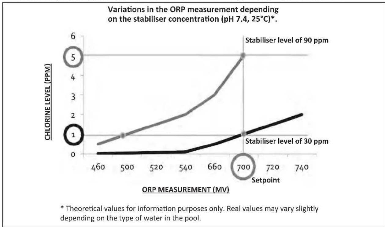
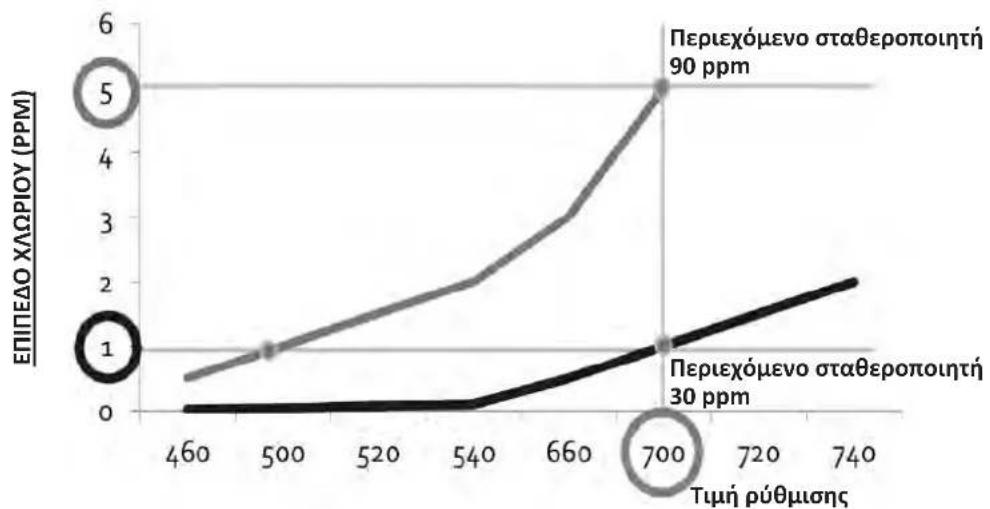
7.2 I Effects of the stabilising agent on chlorine and ORP
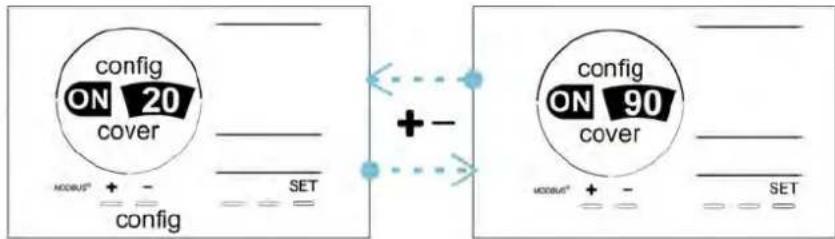
A pool ideally has a stabiliser level of 30 ppm and a pH of 7.4.
1 ppm of free chlorine = 700mV
- The user can therefore adjust the chlorination requirements to 700mV to maintain a level of 1 ppm in the pool.
- If the level of stabiliser rises to 90 ppm, the ORP value will be incorrect and 1 ppm of free chlorine will correspond to 500mV .
- If the user keeps the setpoint at 700mV , a chlorine concentration of 5 ppm will eventually be obtained.
AWARNHINWEISE
ALGEMENE WAARSCHUWINGEN
WAASCHUWINGEN MET BETREKKING TOT ELEKTRISCHE APPARATEN
Sonda PH (conector BNC)*
3
Sonda Redox (conector BNC)*
4
Interruptor ON/OFF
5
Sonda pH (conector BNC)*
3
Sonda Redox (conector BNC)*
4
Interruptor ON/OFF
5
Interru tture ON/OFF
5
AvoTe duo oneC to nWuTou doxetou pH minus, Eikova 2
-Mia onn nou va taipiae i e t n di aetpo tou oawna ( ia va a vappofoe to poiov.
Mia ukpotepn onn yia tny anoophuyn npapauopphioc tou doxeiou kata tn diapkeia tc avappofoonc tou npoiovtoc.
- Pepaote to eueuthetapo akpo tou oawlya avappofo noc (A) diapeou tou πwpatoc onou exete nponyouevwc Kavei tvn kai tonoetne to napexóveo kepaikó epua (EaI to tepauikok akpootoou ouykpatnonc () C otov oawlya, b. Ekova
Bebaiwtheta ot oae ooudeoeic exouyive oot a kal eival oteyavc npotou the ouakeun ae leitoupia.
1
2
3

Mny tootheite to doxeio tou pH minus katw ano tov nektpko eoanou tou xwpou ia aonophyete tov kivduvo diaepwoanc eaiiaic niavw atmuov oecoc.
2.51 Eykaataoan tou kUotiou eIeyxou
2.5.1. Tonoetnon tou kIomega
To kIbwtio eIevxou npenei va eykataoatae i e kaia aepicoevo xwpo, xwpiu ypaosia, ppootateuoevo ano toy nayeto kalakoi agno oioobnntote nooy guvtnongnc nnc napauo nooiov.
To kIbwtio eEyxou npenei va eykataotaotei ae anoataon toulaotov ion 3,5 tpa ano tv akpn tnc niaivac. Na tnpite navtouc kwdukec eykataotaocn h/kau touc loxovtec vououc oto xwpo evkataotaocn.
- Ev npéπe i va eYkataoTaθei o anóσaon μεyalutepn aio 1,6 mtpα aio tv kuψéλn (meyioto mkoq kaωδiou).
Eav to kIbwtio oTepew0e iO stuO, niow ano to kiBwtio npenei va tono0etn0ei eva aiaepoxo netaogua (toulambdaotov 350x250 mm):
- 2epewote to otnipu (napexet) oovto h o taoa, npouonowvctic b8c Kepnouptc (ev npexovtai) (ekov a).
-Too0e1noTe to naw wepoc tou kUwtiou eayxou oTo otnpiyma (Ekova 2
EL
- NaTHoTe To 1uO - loyn mEra2,3,4 n7 wpvv (n "tSt," Aetoupyia Test).
- Patrjote to SET EunBepaiowon tsdipkeia

Tn otiyu nC avtipooh, n xawpiow diakontetai yia liya eenta. Dev emuaviietai kaveva mnuua otnv ofoyn. H kavovikn leitoupyia ouvexietaa mtan vxtipofn.
Ano tn aeitoupyia Configuration/Cover, nathote to SET kai, otn ouvexia, to vua evepyonoiOn kau pOthou eunuonu npoootu npaywyns (diapopwoa o 10% 90%).
- Patnote to SET eIeBaiwon.

EuouBouAri xipnOnc:
- Puθμiσετο ποσστό παραγωγής μεταέι 10% και 30%.
Eav to vepo npaapevei ztoav to kalumu eivai kaeio, eivai npotmuotepo va afoe te auopatn puthetaion Redox va diaxeiptoei tv npaywn xwpiou npaptn aeitoupyia Volet.
4.3.8. Λειτουργία «pH Intelligent»
H eitoupyia 四 pH Intelligent 四 eipenei to pH va puo iicetai eyaultepn akiieia: eiwvei tv npaywn k0w c noiacei to oneio puoianc, nepiopiocovac etoi tci eyaace diakuavoeic oto pH. Anpnoenloyn, autn eitoupyia evai eveyonoinevn. ta va tn aneepyonoine:
Ano tn aeoupyia Configuration/Ini pH, natoe to SET: H evdEiEgN OFF» avaBooBriEi.
- Patnote to yia evepyoioiion (ON) kai yi a puθμon tnc diapkeiaac tnc εanavaΦopac.
- Nathode to SET Eπιβελιωη.

- Euviotatai va evpyonoiote auty tn aeoupyia kai va tv nu puoiee o «1 min» yia va anofoyete tny avenuunn eyxoun tou biopowtikou npoiovtoc tou pH kahe opa nou Eekiva n avtia phiotpavoc.
Pntote to auto to hmu yia evaalayn mela u e maov n c tnc thepokaoic oe aou (oC) kai C F.
4.3.18.BaOmuoPOnnTc ouyKevtpwocAaToC
Ano tvn apxikn oovn, nathote 2 fopec to INED npooaon otic tuec aalatotntac.
- Nathore to CAL yia va Ea eaeAeTe Otn aeitoupyia Baoovopnonc. Tnv oOvN EmaVicetai n evdeiE (Standard).

- Patnote to eauyn autnc tnc aeitoupyia. H evdein aovaooepyie.
- Nathane to yieonoinon tnc tnc.
- Nathode to 24 euiβeβaiωσn.
6.1 I Suvtnpnon twv aoθntnpw
Ola0rntpe npenei va kαθaipiovtai kaθe 2 mvec.
6.3 I 6.3 I 6.3 I 6.3 I 6.3 I 6.3 I 6.3 I 6.3 I 6.3 I 6.3 I 6.3 I 6.3 I 6.3 I 6.3 I 6.3 I 6.3 I 6.3 I 6.3 I 6.3 I 6.3 I 6.3 I
Ia va anofoeuxei n aoKoann aeitoupyia tnc avtlaic, n oTaeun tou doxelou pH-Minus (O) npenei va eEyxetau k0e 2 ec 12 mve c avloay a ne tvv Eykaataon (B. npapakatw ivaka).
Aikouavon tnc metpnoc Redox oevaptnon npoc to eineo oukyevpwong tou oatepponountn (pH 7,4,25°C)*.
METPHsH REDOX (MV)
* OeWpntiKec tuec me eneynyuaKo neio. O npayuatake c uoc nopoe i va diaepouv eaoaipoc avaloya me tov tuno vepou otnv niivia.