
Z400 iQ - Heating ZODIAC - Free user manual and instructions
Find the device manual for free Z400 iQ ZODIAC in PDF.
| Product type | Pool heat pump (heating and cooling) |
| Brand | Zodiac |
| Model | Z400 iQ |
| Dimensions (L x W x H) | 1030 x 450 x 479 mm (models MD4/MD5/MD7/TD7) or 1145 x 480 x 509 mm (models MD8/TD8/MD9/TD9) |
| Net weight | 70 to 110 kg depending on model |
| Power supply | 220-240V single-phase or 380-415V three-phase, 50 Hz |
| Operating temperature range (air) | -12 to 40 °C (depending on model) |
| Operating temperature range (water) | 15 to 32 °C |
| Refrigerant type | R32 (flammable A2L) |
| Refrigerant charge | 0.87 to 1.80 kg depending on model |
| Average water flow rate | 4 to 8 m³/h depending on model |
| Pressure drop | 1.1 to 1.5 mCE |
| Service pressure (water circuit) | 1.5 bar (max 3 bar) |
| Sound power (Boost mode) | 64 to 68 dB(A) depending on model |
| Sound power (Silence mode) | 61 to 66 dB(A) depending on model |
| Protection rating | IP24 |
| Main functions | Heating, cooling (Cool mode), Silence mode, Boost mode, heating priority, remote control, iAquaLink™ app, keypad lock |
| Wireless connection | Wi-Fi 2.4 GHz, iAquaLink™ app (iOS/Android) |
| Maintenance | Clean the evaporator with a soft brush and freshwater spray; exterior with solvent-free product; annual maintenance by qualified technician |
| Safety | Residual current device 30 mA, automatic shutdown on fault, refrigerant leak detection, frost protection, shutdown if insufficient flow or outdoor temperature out of range |
Frequently Asked Questions - Z400 iQ ZODIAC
User questions about Z400 iQ ZODIAC
0 question about this device. Answer the ones you know or ask your own.
Ask a new question about this device
Download the instructions for your Heating in PDF format for free! Find your manual Z400 iQ - ZODIAC and take your electronic device back in hand. On this page are published all the documents necessary for the use of your device. Z400 iQ by ZODIAC.
USER MANUAL Z400 iQ ZODIAC
natural_image
Line drawing of an iAquaLink air conditioner unit (no text or symbols on the device itself)Instructions for installation and use - English Heat pump
Translation of the original instructions in French
natural_image
Illustration of two people pulling a table with legs, no text or symbols presentA : Sangle
1.2 | Raccordements hydrauliques
natural_image
Technical line drawing of a device with screwdriver and internal components (no text or symbols)②
natural_image
Technical line drawing of a device casing with internal components (no text or symbols)natural_image
Diagram of a mechanical assembly with a tool inserted, showing internal components and no text or symbols.2
natural_image
Diagram of a mechanical assembly with a tool interacting with a component, showing internal parts and no visible text or symbols.natural_image
Line drawing of a rectangular electronic device with ventilation grilles and mounting brackets (no text or symbols)
©

natural_image
Two chemical products: a white plastic container labeled 'PAC NET' and a spray bottle with a black tip (no visible text or symbols on the main objects)Read the instructions in this manual carefully before using the device.

The appliance contains R32.
- Before handling the appliance, it is vital that you read this installation and user manual, as well as the “Warranty” booklet delivered with the appliance. Failure to do so may result in material damage or serious or fatal injury and will void the warranty.
- Keep and pass on these documents for later viewing throughout the appliance's service life.
- The distribution or modification of this document in any way is prohibited, without prior authorisation from Zodiac®.
- Zodiac® is constantly developing its products to improve their quality; therefore, the information contained in this document may be modified without notice.
GENERAL WARNINGS
- Failure to respect the warnings may cause serious damage to the pool equipment or cause serious injury, even death.
- Only a person qualified in the technical fields concerned (electricity, hydraulics or refrigeration) is authorised to perform any servicing (or repairs to the appliance. The qualified technician working on the appliance must use/wear personal protective equipment (such as safety goggles and protective gloves, etc.) in order to reduce the risk of injury occurring when working on the appliance.
- Before handling the machine, ensure that the power is switched off and isolated from the power supply.
- The appliance is intended to be used for pools and spas for a specific purpose; it must not be used for any purpose other than that for which it was designed.
- This appliance is not intended for use by persons (including children) with reduced physical, sensory or mental capabilities, or lack of experience and knowledge, unless they have been given supervision or instruction concerning use of the appliance by a person responsible for their safety. Children should be supervised to ensure that they do not play with the appliance.
- This appliance can be used by children aged from 8 years and above and persons with reduced physical, sensory or mental capabilities or lack of experience and knowledge if they have been given supervision or instruction concerning use of the appliance in a safe way and understand the hazards involved. Children shall not play with the appliance. Cleaning and user maintenance shall not be made by children without supervision.
- The appliance must be installed according to the manufacturer's instructions and in compliance with local standards. The installer is responsible for installing the appliance and for compliance with national installation regulations. Under no circumstances may the manufacturer be held liable in the event of failure to comply with applicable local installation standards.
- For any work other than the simple user maintenance described in this manual, the product should be referred to a qualified professional.
- If the appliance suffers a malfunction, do not try to repair it yourself; instead contact a qualified technician.
- Refer to the warranty conditions for details of the permitted water balance values for operating the appliance.
- Deactivating, eliminating or by-passing any of the safety mechanisms integrated into the appliance shall automatically void the warranty, in addition to the use of spare parts manufactured by unauthorised third-party manufacturers.
- Do not spray insecticide or any other chemical (inflammable or non-inflammable) in the direction of the appliance, as this may damage the body and cause a fire.
- Do not touch the fan or moving parts and do not place any objects or your fingers in the vicinity of the moving parts during operation of the appliance. Moving parts can cause serious injury or even death.
WARNINGS ASSOCIATED WITH ELECTRICAL APPLIANCES
- The electrical supply to the appliance must be protected by a 30 mA differential Residual Current protection Device (RCD), complying with the standards and regulations in force in the country in which it is installed.
- For Australia and New-Zealand, this product must be installed and serviced by a licensed electrician in accordance with AS/NZ 3000 - latest published/enforced edition, and any other local regulations.
- Do not use any extension lead when connecting the appliance; connect the appliance directly to a suitable power supply circuit.
-
Before carrying out any operations, check that:
-
The voltage indicated on the appliance information plate corresponds to the mains voltage.
- The power grid is adapted to the power requirements of the appliance, and is grounded.
- In the event of anormal operation or the release of unusual odours from the appliance, turn it off immediately, unplug it from its power supply and contact a professional.
- Before any access to the appliance for service or maintenance, ensure that it is switched off and completely disconnected from the power supply. Furthermore, in addition to confirming that the heating priority (where applicable) is deactivated, ensure that any other equipment or accessories connected to the appliance are also disconnected from the power supply circuit.
- Do not disconnect and reconnect the appliance to the power supply when in operation.
- Do not pull on the power cord to disconnect it from the power supply.
- If the power cord is damaged, it must be replaced by the manufacturer, its technician or a qualified person to guarantee safety.
- Do not perform maintenance or servicing operations on the appliance with wet hands or if the appliance is wet.
- Before connecting the appliance to the source of supply, ensure that the terminal block or supply socket to which the appliance will be connected is in good condition and is not damaged or corroded in any way.
- For any component or sub-assembly containing a battery: do not recharge or dismantle the battery, or throw it into a fire. Do not expose it to high temperatures or direct sunlight.
- In stormy weather, disconnect the appliance from the power supply to prevent it from suffering lightning damage.
- Do not immerse the appliance in water or mud.
WARNINGS CONCERNING APPLIANCES CONTAINING REFRIGERANT
- Do not release R32 fluid into the atmosphere. These are fluorinated greenhouse gases, covered by the Kyoto Protocol, with a Global Warming Potential (GWP) of 675 for R32 (see EU Regulation 517/2014 on fluorinated greenhouse gases).
- In order to comply with relevant environmental and installations standards and regulations such as, but not limited to, French decree No. 2015-1790 and/or the EU Regulation EU 517/2014, the cooling circuit must be checked for leakage at least once a year. This operation must be carried out by a certified cooling appliance specialist.
WARNINGS CONCERNING APPLIANCES CONTAINING R32 REFRIGERANT
- This device contains R32 refrigerant, a class A2L refrigerant, which is considered to be potentially flammable.
- The device must be stored in a ventilated place away from all sources of fire.
- Install the unit outdoors. Do not install the unit indoors or in an enclosed, non-ventilated area outdoors.
- Do not use means to accelerate the defrosting process or to clean, other than those recommended by the manufacturer.
- The appliance shall be stored in a room without continuously operating ignition sources (for example: open flames, an operating gas appliance or an operating electric heater).
- Do not pierce or burn.
- Be aware that refrigerants may not contain an odour.
INSTALLATION AND MAINTENANCE
- The appliance may not be installed close to combustible materials, or an air duct inlet of an adjacent building.
- With some appliances, it is essential to fit protection grids if the unit is installed in an area with uncontrolled access.
- During installation, troubleshooting and maintenance, pipes may not be used as steps: the pipe could break under the weight, spilling coolant and possibly causing serious burns.
- When servicing the appliance, the composition and state of the heat transfer fluid must be checked, as well as the absence of any traces of coolant.
- During the appliance's annual sealing test in accordance with applicable legislation, the high and low pressure switches must be checked to ensure that they are securely fastened to the cooling circuit and that they cut off the electrical circuit when tripped.
- During maintenance work, ensure there are no traces of corrosion or oil around the cooling components.
- Before beginning work on the cooling circuit, stop the appliance and wait for a few minutes before fitting the temperature and pressure sensors. Some elements such as the compressor and piping may reach temperatures in excess of 100°C and high pressures with the consequent risk of severe burns.
TROUBLESHOOTING
- All soldering work must be carried out by a someone qualified to do so.
- Replacement pipes must always be made of copper in compliance with standard NF EN 12735-1.
- Leak detection, pressure test:
- never use oxygen or dry air (risk of fire or explosion)
- use dry nitrogen or the mixture of nitrogen and coolant indicated on the information plate,
- the test pressure for both the high and low pressure circuits must not exceed 42 bar if the appliance is equipped with the optional pressure gauge.
- The high pressure circuit pipes are made of copper and have a diameter equal to or greater than 1"5/8. A certificate as indicated in §2.1 in compliance with standard NF EN 10204 will be requested from the supplier and filed with the facility's technical documentation.
- Technical data relative to the safety requirements of the various applicable directives are indicated on the information plate. All this information must be recorded in the appliance's installation manual, which must be kept in the its technical file: model, code, serial number, maximum and minimum OT, OP, year of manufacture, CE marking, manufacturer's address, coolant and weight, electrical parameters, thermo-dynamic and acoustic performance.
LABELLING
- Equipment shall be labelled stating that it has been decommissioned and emptied of refrigerant.
• The label shall be dated and signed. - For appliances containing flammable refrigerants, ensure that there are labels on the equipment stating the equipment contains flammable refrigerant.
RECOVERING
- When removing refrigerant from a system, either for servicing or decommissioning, it is recommended good practice that all refrigerants are removed safely.
- When transferring refrigerant into cylinders, ensure that only appropriate refrigerant recovery cylinders are employed. Ensure that the correct number of cylinders for holding the total system charge is available. All cylinders to be used
are designated for the recovered refrigerant and labelled for that refrigerant (i.e. special cylinders for the recovery of refrigerant). Cylinders shall be complete with pressure-relief valve and associated shut-off valves in good working order. Empty recovery cylinders are evacuated and. if possible, cooled before recovery occurs.
- The recovery equipment shall be in good working order with a set of instructions concerning the equipment that is at hand and shall be suitable for the recovery of all appropriate refrigerants including, when applicable, flammable refrigerants. In addition, a set of calibrated weighing scales shall be available and in good working order. Hoses shall be complete with leak-free disconnect couplings and in good condition. Before using the recovery machine, check that it is in satisfactory working order, has been properly maintained and that any associated electrical components are sealed to prevent ignition in the event of a refrigerant release. Consult manufacturer it in doubt.
- The recovered refrigerant shall be returned to the refrigerant supplier in the correct recovery cylinder, and the relevant waste transfer note arranged. Do not mix refrigerants in recovery units and especially not in cylinders.
- If compressors or compressor oils are to be removed, ensure that they have been evacuated to an acceptable level to make certain that flammable refrigerant does not remain within the lubricant. The evacuation process shall be carried out prior to returning the compressor to the suppliers. Only electric heating to the compressor body shall be employed to accelerate this process. When all is drained from a system, it shall be carried out safely.
Recycling
This symbol is required by European Community Directive 2012/19/UE on WEEE (Waste Electrical and Electronic Equipment) and means that your appliance must not be thrown into a normal bin. It will be selectively collected for the purpose of reuse, recycling or transformation. Any substances it may contain which are potentially dangerous to the environment shall be eliminated or neutralised. Request information on recycling procedures from your retailer.
CONTENTS

1 Installation 6
1.1 I Selecting the location 6
1.2 | Hydraulic connections 8
1.3 | Accessing the electrical connection terminal boards 9
1.4 | Power connections 9
1.5 | Connecting options 10

② Use 11
2.1 | Operating principle 11
2.2 | User interface presentation 12
2.3 | Operation 13
2.4 | User functions 14
2.5 I Connection to the iAquaLink™ app 15

3 Maintenance 16
3.1 | Winterizing 16
3.2 | Maintenance 16

4 Troubleshooting
4.1 | Appliance behaviour 19
4.2 | Error code display 20
4.3 | Lighting of LEDs on the printed circuit board 21
4.4 | Wiring diagrams 21

5 Characteristics
5.1 | Description 22
5.2 | Technical specifications 23
5.3 | Dimensions and marking 23

Tip: to make it easier to contact your retailer
- Write down your retailer's contact details to help you find them more easily and fill in the "product" information on the back of the manual; your retailer will ask you for this information.

1 Installation
1.1 I Selecting the location

- The appliance must be installed at 2 metres, minimum, from the surrounding edge of the pool.
- Do not lift the appliance by the body; use straps (not provided, see § "1.1.1 | Setting up the device").
- Exercise care during handling of the device. The evaporator (marking Ⓞ in § "5.3 I Dimensions and marking") can be easily damaged.
- The evaporator (marking Ⓞ in § "5.3 I Dimensions and marking") may contain sharp edges which can cause injury. In order to prevent any injury, wear protective gloves during servicing operations which may involve contact with the evaporator.

- Only an outdoor installation is possible, provide free space around the appliance according to diagram § "1.2 I Hydraulic connections".
- Place the appliance on its anti-vibration blocks (integrated under its base, height adjustable) on a stable, solid and level surface,
- This surface must be able to bear the weight (voir § 5.2 I "Technical specifications") of the appliance (in particular in the case of installation on a roof, a balcony or any other support).
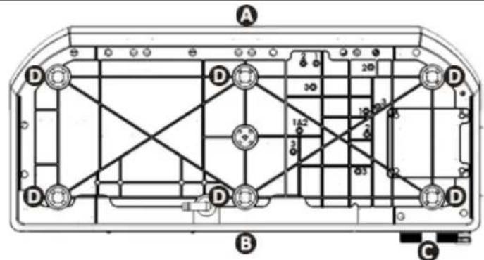
View of the appliance base from below for installing the anti-vibration blocks (MD4 / MD5 / MD7 / TD7 models)
A: front
B: rear
©: connections
D: Anti-vibration blocks
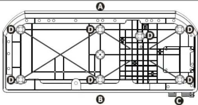
View of the appliance base from below for installing the anti-vibration blocks (MD8 / TD8 / MD9 / TD9 models)
The appliance must not be installed:
- With the blowing towards a permanent or temporary obstacle (awning, brushwood, etc.) less than 5 metres away,
- Within range of water or mud jets, sprays or run-off (take the effect of the wind into account),
• Near a heat source or flammable gas,
• Near high-frequency equipment, - In a location where it would be subject to snow build-up,
- In a location where it might be flooded by the condensates produced by the appliance when operating.

Tip: reduce any noise annoyance from your heat pump
- Do not install it under or towards a window.
- Do not tilt it towards your neighbours.
• Install it in an open space (sound waves are reflected on surfaces). - Install an acoustic screen around the heat pump, respecting the distances (see diagram § «1.2 I Hydraulic connections»).
• Install 50 cm of flexible PVC pipe at the heat pump water inlet and outlet to absorb vibrations. - Increase the filtration time by 50% and activate "silence" mode. The heat pump will run for longer with less power, but much more quietly and with an improved COP (energy savings). «Silence» mode is particularly well suited for maintaining the water temperature once the setpoint temperature has been reached.
1.1.1 Setting up the device
- Use straps (not supplied) to lift the device to prevent damage during installation.
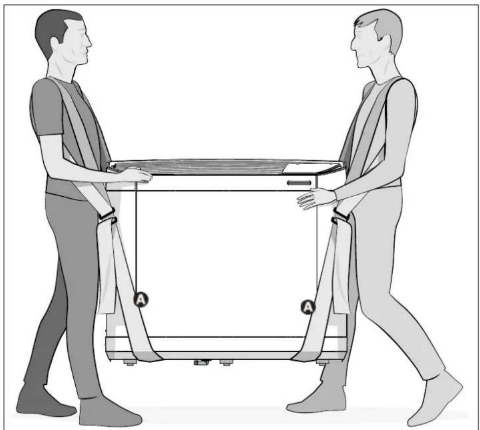
natural_image
Illustration of two people pulling a table with a cart, no text or symbols presentA : Strap
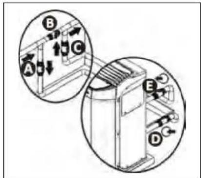
1.2 | Hydraulic connections
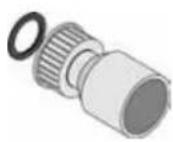
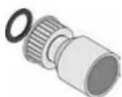
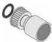
- The device will be connected with a ∅50 PVC pipe, using the half union connectors supplied (see § "5.1 I Description"), to the pool's filtration circuit, after the filter and before the water treatment.
- Respect the direction of hydraulic connection.
- A by-pass must be installed to make it easier to work on the appliance.
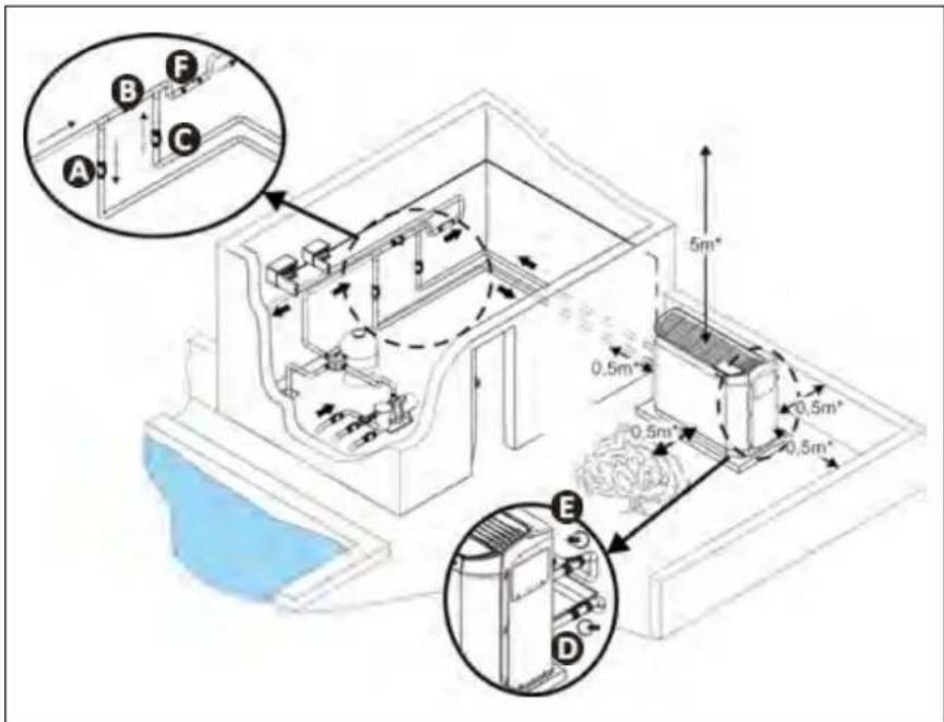
A: water inlet valve
B: by-pass valve
©: water outlet valve
D: water inlet adjustment valve (optional)
E: water outlet adjustment valve (optional)
F: water treatment
* minimum distance
- To evacuate the condensates, fit a 18 pipe on the grooved elbow mounted under the appliance base.
- The elbow can be oriented at an angle of 280^ beneath the appliance.
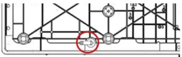
Condensate drainage elbow (view of the device from below)

Tip: condensate drainage
Caution, several litres of water can be drained from your appliance each day. We strongly recommend connecting the drain to a suitable water drainage system.
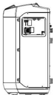
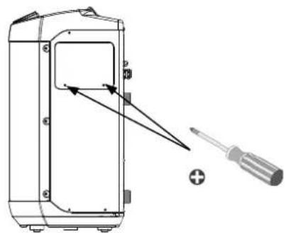
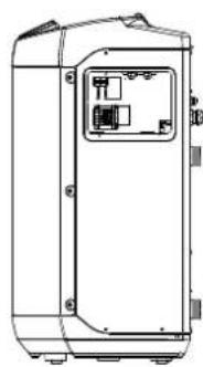
1.3 | Accessing the electrical connection terminal boards
1
natural_image
Technical line drawing of a device with screwdriver and component, no text or symbols presentUnscrew the 2 screws Slide the door downwards
2
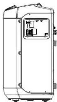
natural_image
Technical line drawing of a rectangular electronic device with internal components (no text or symbols)1.4 | Power connections

- Before any work inside the appliance, you must cut the electricity supply to the appliance as there is a risk of electric shock which may cause material damage, serious injury or even death.
- Incorrectly tightened terminals may cause the terminal box to heat up, which can invalidate the warranty.
- Only a qualified and experienced technician is authorised to carry out cabling work within the appliance or to replace the power cord.
-
The installer must consult the electricity provided if necessary and ensure that the equipment is connected correctly to an electricity network with impedance under 0.095 ohm.
-
The heat pump's electrical supply must be provided through a protection and circuit breaking device (not supplied) complying with the standards and regulations in force in the country where it is installed,
- The appliance is provided for connection to a general power supply with a TT or TN.S neutral regime.
- Electrical protection: by circuit breaker (D curve, rating to be defined according to the table § "5.2 I Technical specifications"), with a suitable dedicated differential protection device (circuit breaker or switch).
• Additional protection may be required during installation to guarantee the II overvoltage category. - The power supply must correspond to the voltage indicated on the appliance's information plate.
- The power cord must be insulated against any cutting or hot elements that may damage or crush it.
- The appliance must be connected to an earth socket.
• The electrical connection lines must be fixed. - Use the gland to pass the power cord into the appliance.
- Use the power cord (RO2V type) adapted for outdoor or buried use (or run the cable into a protection duct) with an external diameter of between 9 and 18mm.
• We recommend burying the cable at a depth of 50 cl (85 cm under a road or path) in an electrical duct (red ribbed). - If this buried cable meets another cable or pipe (gas, water, etc.), there must be more than 20 cm between them.
- Connect the power supply cord to the spring-cage terminal block (see § 1.4.1 I Wiring on a spring-cage terminal block) inside the appliance.
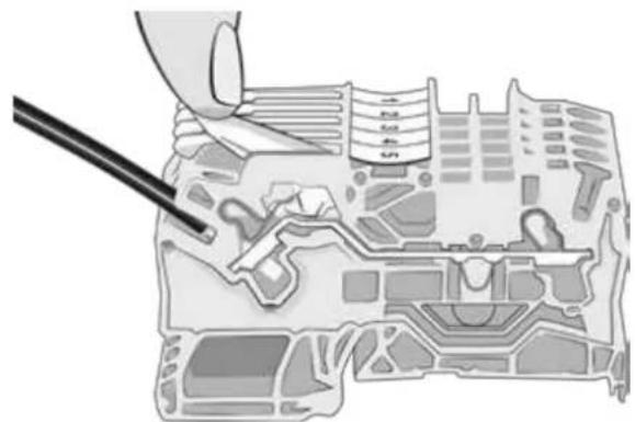
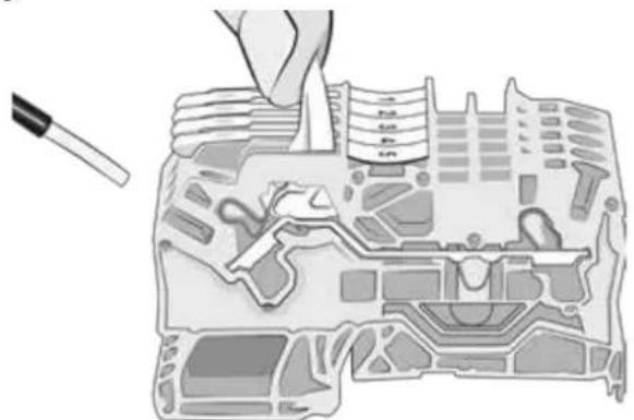
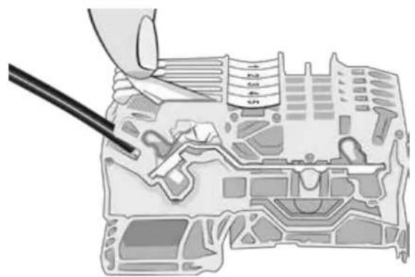
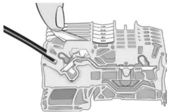
1.4.1 Wiring on a spring-cage terminal block
- Pull the lever to the maximum, then connect the cable(s) (see picture 1).
- Return the lever to its original position (see image 2).
1
natural_image
Illustration of a hand using a tool to adjust or install electronic components on a circuit board (no text or symbols visible)2

natural_image
Diagram of a mechanical assembly with a tool inserted, showing internal components and no visible text or symbols.
1.5 | Connecting options

Connecting the "Heating priority" and "On/off command" options:
- Before any work inside the appliance, you must cut the electricity supply to the appliance as there is a risk of electric shock which may cause material damage, serious injury or even death.
- There is a risk of electrical return current, injuries, material damage and death when working on terminals 1 to 8.
- Any connection error with terminals 1 to 8 may damage the appliance and invalidated its warranty.
- Terminals 1 to 8 are dedicated to the options and must never be used to directly supply other equipment.
- Use cables with a section of at least 2x0.75 mm ^2 , RO2V type and with a diameter between 8 and 13 mm.
Before connecting any options: remove the seal (above the cable gland) and install the cable gland provided in order to pass the cables into the appliance. The cables used for the options and the power cord must be kept separate (risk of interference) using a collar inside the appliance just after the glands.
1.5.1 "Heating priority" option
- This function helps to keep the water temperature constant by checking the water temperature at regular time intervals (minimum 5 minute cycle every 120 minutes) by filtration pump control. The filtration is kept operating if the pool temperature is below the temperature requested.
- For the connection, connect the filtration timer to terminals 1 and 2 (dry contact, no polarity, maximum intensity 8A).
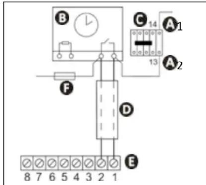
A1-2 power for the filtration pump power contactor coil
B: filtration timer
C: power contactor (tripolar or bipolar) for the filtration system pump motor
D: separate cable for the "heating priority" function
E: heat pump terminal board
F: fuse
1.5.2 Remote "on/off" control option
- This option enables the "on/off" button function to be transferred via a switch or a home automation system installed remotely.
- For the connection, remove the shunt between terminals 7-8 and connect the wire of the switch in place (potential free contact, no polarity, 220-240V \~ 50Hz).
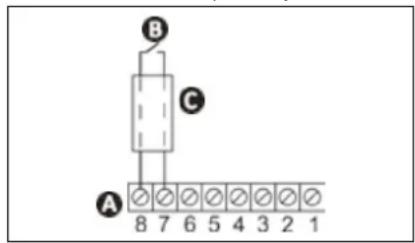
A: heat pump terminal board
B: remote "on/off" switch
©: separate connection wire
2.1 | Operating principle
2.1.1 General operation
Your heat pump uses the calories (heat) in the air to heat up your pool's water. The process to heat your pool's water to the temperature you want may take a few days as it depends on the weather conditions, your heat pump's power and the difference between the water temperature and the temperature you want.
The warmer and damper the air, the better your heat pump will perform. The outdoor parameters for optimum operation are an air temperature of 27^ C, a water temperature of 27^ C and 80% relative humidity.

Tip: improve your pool's temperature rise and maintenance
- Anticipate the commissioning of your pool far enough in advance before you use it.
- For the temperature rise, set the water circulation to continuous operation (24/24).
- To maintain the temperature throughout the season, run "automatic" circulation for at least 12 hours/day (the longer this time the longer the heat pump will have enough operating range to heat up).
- Cover the pool with a sheet (bubble canopy, canvas, etc.) to prevent heat loss.
- The heat pump will be even more efficient if it operates during the warmest hours of the day.
- Keep the evaporator clean.
- Set the temperature you want and let the heat pump run (adjusting the setpoint to maximum will not heat the water more quickly).
- Connect the "Heating priority"; the filtration pump and heat pump operating time will be set according to requirements.
2.1.2 Operating modes (default settings)
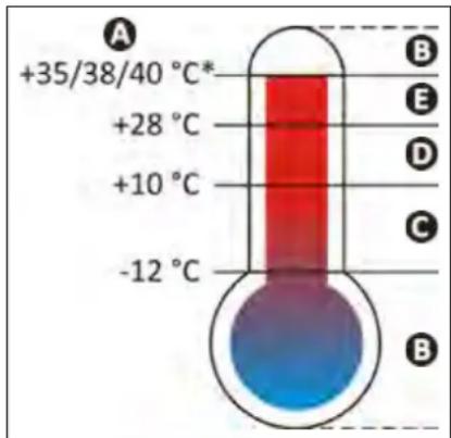
A: External air temperature
B: Heat pump shutdown, outside of operating range
C: Forced "Boost" mode
D: Possibility of selecting the "Boost" or "Silence" operating mode
E: Forced "Silence" mode
* depending on model, see § 《5.2 | Technical specifications》 page 26.
2.1.3 Precautions

- Even though the appliance can be used all year round, certain precautions must be taken to avoid damaging the condenser (for the precautions specific to winterising, refer to § 3.1).
- If the heat pump is subjected to extended exposure to negative outdoor temperatures (excluding winterising period), you must:
- Activate the “Heating Priority” option: the filtration pump will operate while the pool’s temperature is below the heat pump’s setpoint temperature. If the setpoint is reached, the pump will operate for 5 minutes every 2 hours.
- Make sure that the pool's filtration pump is activated at least every 4 hours if the "Heating Priority" option is not activated on the heat pump.

2.2 | User interface presentation

- To lock or to unlock the keypad: simultaneously press ∧ and ∨ for 3 seconds.
2.2.1 Presentation of the display screen and function keys
 | Actual water temperature**Displays the temperature measured during the last operation of the heat pump. |
 | "On/off" buttonGo back in the menus |
 | Change settings buttonActivate/deactivate "Silence" mode |
 | Value setting buttons |
2.2.2 Description of the display screen
| Symbol | Name Steady Flashing Off | |||
 | Water flow Water flow okay | Water flow too low or missing | Appliance switched off | |
| ### | Air temperature / | Air temperature out of operating range | Air temperature in the operating range | |
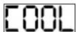
| [0x4K] | "Cold" mode "Cold" mode activated / | "Cold" mode desactivated | ||
| [65X4] | "Silence" mode | "Silence" mode activated | / | "Silence" mode desactivated |
| ### | Wi-Fi Wi-Fi connected | Wi-Fi pairing in progress | Wi-Fi not connected |
2.2.3 Description of the LEDs showing the «appliance status»
| LED Appliance status Meaning | ||
| Steady green | OK | Temperature reached or operation in "hot" mode |
| Steady blue | OK | Operation in "cold" mode |
| Steady red | Error in progress | Error in progress, see error message on the interface and meaning (see § "4.2 I Error code display") |
| Flashing red | Stopped | The appliance shuts down after more than 4 errors in one hour and requires a manual restart after correcting the error (see § "4.2 I Error code display") |
| Off | Stopped | Device off or not connected to the power supply |

2.3 | Operation
- Check that there are no tools or other foreign objects in the machine.
- The panel that provides access to the technical section (see § 《5.3 I Dimensions and marking》) must be put back in place.
- Set the valves as follows: valve B wide open, valves A, C, D and E closed.
A: water inlet valve
B: by-pass valve
©: water outlet valve
D: water inlet adjustment valve (optional)
E: water outlet adjustment valve (optional)

- An incorrect by-pass setting may cause the heat pump to malfunction.
- Check that the hydraulic connections are correctly tightened and that there are no leaks.
- Check that the appliance is stable.
- Turn on the water flow (by activating filtration).
- Close valve B gradually so that the filter pressure is increased by 150g (0.150 bars).
- Open valves A, C and D fully then valve E by half (the air which has built up in the heat pump condenser and the filtration circuit will bleed out). If valves D and E are not present, open valve A wide and close valve C by half.
- Connect the power supply to the heat pump.
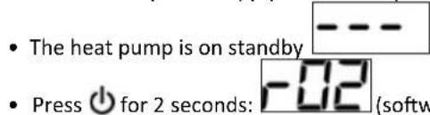
the last water temperature measured is then displayed 28. This value varies depending on the last temperature recorded during the last connection.

If no water flow was present during the last connection, the screen will display the value
- Set the desired temperature (called the "temperature setpoint") (see § "2.4.2 Adjusting the temperature setpoint").
After the start-up steps for your heat pump:
- Shut down the water circulation temporarily (by stopping the filtration or closing valve B or C) to check that you appliance stops after a few seconds (via the activation of the flow switch).
- Reduce the setpoint temperature to below the water temperature to check that the heat pump stops operating.
- Switch off the heat pump by pressing and holding ⏻ for 2 seconds and check that it stops.

2.4 I User functions
2.4.1 Locking/unlocking the keyboard
To lock or to unlock the keypad, press and hold and simultaneously for 3 seconds: or .
2.4.2 Adjusting the temperature setpoint
- Press or: the temperature setpoint is displayed and flashes,
- Press to increase the temperature by 0.5^^* ,
- Press to reduce the temperature by 0.5^^** .
- Press to confirm the desired setpoint temperature.
- The settings screen is automatically exited after 3 seconds of inactivity on the keypad or by pressing and releasing ⏻. The heat pump stops automatically when the pool reaches the required temperature.
*Maximum setpoint temperature = 32 °C.
**Minimum setpoint temperature = 15 °C.

If the setpoint temperature has not been confirmed by pressing SET, it will not be saved if the interface returns to the home screen (which takes place automatically after 3 seconds of inactivity on the keypad or by pressing and releasing 🔒)
2.4.3 Activating/deactivating "silence" mode
«Silence» mode is used to reduce the noise level emitted by the heat pump. The appliance will operate for a longer period of time with less power, however with a lower noise level.
There are 2 ways to activate the "Silence" mode:
1^st method
- Press and release, the symbol will right up.
2^nd method
- Press and hold

- Press or to display: .

- Press and release 📄, the symbol 📋 will light up.
- The home screen automatically reappears after 60 seconds of inactivity on the keypad or by pressing and releasing ⏻. To deactivate the "Silence" mode, redo the manipulation, the symbol will go out.
2.4.4 Activating/deactivating "cold" mode
Activation of «Cold» mode allows the machine's cycle to be automatically reversed to cool the pool water when it exceeds the setpoint temperature by more than 2°C.
- Press and hold SET
- Press or to display :
- Press and release, the symbol will light up.
- The home screen automatically reappears after 60 seconds of inactivity on the keypad or by pressing and releasing ⏻.
To deactivate the "cold/cooling" mode, redo the manipulation, the symbol ⚙ will go out.

«Cold» mode does not allow cooling to be activated manually. For immediate activation, activate «Cold» mode then return to the main screen and lower the setpoint temperature to at least 2 degrees below the measured water temperature.
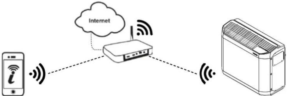
2.5 I Connection to the iAquaLink™ app
flowchart
graph TD
    A["Mobile Phone i"] -->|Wireless Signal| B["Rutier"]
    B -->|Wireless Signal| C["Air/Condenser"]
    B -.->|Internet| B
    style A fill:#f9f,stroke:#333
    style B fill:#ccf,stroke:#333
    style C fill:#cfc,stroke:#333
The Z400iQ heat pump may be controlled by remote, from a smartphone or tablet, via the iAquaLink™ app available for iOS and Android systems.

Before you install the app, you must:
- Use a smartphone or tablet connected to Wi-Fi.
- Use a Wi-Fi network with a reasonably powerful signal when connecting to the heat pump.
-
Have your home Wi-Fi network password at the ready.
-
Download the iAquaLink™ app from the App Store (iOS) or Google Play Store (Android) then create an iAquaLink™ account (if the app is already installed, move onto the next step).
②. Open the app then add the heat pump to the list of appliances, following the steps described on the smartphone or tablet.

- For the first step (pairing), stay near the appliance.

③ Maintenance
3.1 | Winterizing

- Although the device may be used year around, in the event that it will not be used during the winter months, proper winterizing is necessary in order to prevent damage to the condenser. Damage due to failure to properly winterize the unit when it is not use is not covered by the warranty.
-
To prevent condensation from damaging the appliance: cover the appliance with the winterising cover supplied (do not hermetically-seal the appliance inside a cover).
-
Set the regulator to "standby" mode by pressing and holding ⏻ for 2 seconds and disconnect the power supply,
- Open valve B,
- Close valves A and C and open valves D and E (if present),
- Make sure that there is no water circulating in the heat pump,
- Drain the water from the condenser (risk of freezing) by unscrewing the two water inlet and outlet connectors on the back of the heat pump,
- In the case of full winterizing for the pool (complete shutdown of the filtration system, bleed the filtration circuit or even pool drainage): tighten the two connectors by one turn to prevent any foreign bodies from getting into the condenser,
- In the case of winterizing for the heat pump only (shutdown of the heating only, the filtration keeps running): to not tighten the connectors but add 2 caps (provided) on the condenser's water inlets and outlets.
- We recommend that you put the aired winterizing micro cover (provided) on the heat pump.
3.2 | Maintenance

- Before performing any maintenance operation on the appliance, you must cut the electricity supply as there is a risk of electric shock which may cause material damage, serious injury or even death.
- It is recommended that the appliance undergo general servicing at least on a yearly basis to ensure proper operation, maintain performance levels and potentially prevent certain failures. These operations are carried out at the user's expense by a qualified technician.
3.2.1 Safety instructions concerning appliances containing R32 refrigerant
Area check
- Prior to beginning work on systems containing flammable refrigerants, safety checks are necessary to ensure that the risk of ignition is minimised.
Work procedure
- Work shall be undertaken under a controlled procedure so as to minimise the risk of a flammable gas or vapour being present while the work is being performed.
General work area
- All maintenance staff and others working in the local area shall be instructed on the nature of work being carried out. Work in confined spaces shall be avoided.
Check for the presence of refrigerant
- The area shall be checked with an appropriate refrigerant detector prior to and during work, to ensure the technician is aware of potentially toxic or flammable atmospheres. Ensure that the leak detection equipment being used is suitable for use with all applicable refrigerants, i.e. non-sparking, adequately sealed or intrinsically safe.
Check for the presence of a fire extinguisher
- If any work involving heat is to be conducted on the refrigerating equipment or any associated parts, appropriate fire extinguishing equipment shall be available to hand. Have a dry powder or CO _2 , fire extinguisher adjacent to the charging area.
No source of ignition
- No person carrying out work in relation to a refrigerating system which involves exposing any pipe work shall use any sources of ignition in such a manner that it may lead to the risk of fire or explosion. All possible ignition sources, including cigarette smoking, should be kept sufficiently far away from the site of installation, repairing, removing and disposal, during which refrigerant can possibly be released to the surrounding space. Prior to work taking place, the area around the equipment is to be surveyed to make sure that there are no flammable hazards or ignition risks. «No Smoking» signs shall be displayed.
Area ventilation
- Prior to penetrating the unit in any way to perform any required service, ensure that the area is open and adequately ventilated. Proper ventilation, to allow for safe dispersion of any refrigerant which may be inadvertently released to the atmosphere, should be maintained while service is being performed on the unit.
Refrigeration equipment check
- The manufacturer's service and maintenance guidelines must be followed at all times. When replacing any electrical components, be sure to use only components which are of the same type and rating and which are recommended/approved by the manufacturer. If in doubt, consult the manufacturer's technical department for assistance.
- The following checks shall be applied to installations using flammable refrigerants:
- if an indirect refrigerating circuit is being used, the secondary circuit shall be checked for the presence of refrigerant;
- Marking to the equipment continues to be visible and legible. Markings and signs that are illegible shall be corrected;
- refrigerating pipe or components are installed in a position where they are unlikely to be exposed to any substance which may corrode refrigerant containing components, unless the components are constructed of materials which are inherently resistant to being corroded or are suitably protected against being so corroded.
Electrical component check
- Repair and maintenance to electrical components shall include initial safety checks and component inspection procedures. If a fault exists that could compromise safety, then no electrical supply shall be connected to the circuit until it is satisfactorily dealt with. If the fault cannot be corrected immediately but it is necessary to continue operation, an adequate temporary solution shall be used. This shall be reported to the owner of the equipment so all parties are advised.
- Initial safety checks shall include:
- that capacitors are discharged: this shall be done in a safe manner to avoid possibility of sparking;
- that no live electrical components and wiring are exposed while charging, recovering or purging the system;
- that there is continuity of earth bonding.
Repair of insulated components
- During repairs to sealed components, all electrical supplies shall be disconnected from the equipment being worked upon prior to any removal of sealed covers, etc. If it is absolutely necessary to have an electrical supply to equipment during servicing, then a permanently operating form of leak detection shall be located at the most critical point to warn of a potentially hazardous situation.
- Particular attention shall be paid to the following to ensure that by working on electrical components, the casing is not altered in such a way that the level of protection is affected. This shall include damage to cables, excessive number of connections, terminals not made to original specification, damage to seals, incorrect fitting of glands, etc.
- Ensure that the apparatus is mounted securely.
- Ensure that seals or sealing materials have not degraded to the point that they no longer serve the purpose of preventing the ingress of flammable atmospheres. Replacement parts shall be in accordance with the manufacturer's specifications.
Repair of intrinsically safe components
- Do not apply any permanent inductive or capacitance loads to the circuit without ensuring that this will not exceed the permissible voltage and current permitted for the equipment in use.
- Intrinsically safe components are the only types that can be worked on while live in the presence of a flammable atmosphere. The test apparatus shall be at the correct rating.
- Replace components only with parts specified by the manufacturer. Other parts may result in the ignition of refrigerant in the atmosphere from a leak.
Wiring
- Check that cabling will not be subject to wear, corrosion, excessive pressure, vibration, sharp edges or any other adverse environmental effects. The check shall also take into account the effects of aging or continual vibration from sources such as compressors or fans.
Detection of flammable refrigerant
- Under no circumstances shall potential sources of ignition be used in the searching for or detection of refrigerant leaks. A halide torch (or any other detector using a naked flame) shall not be used.
- The following leak detection methods are deemed acceptable for all refrigerant systems.
- Electronic leak detectors may be used to detect refrigerant leaks but, in the ease of flammable refrigerants, the sensitivity may not be adequate, or may need re-calibration. (Detection equipment shall be calibrated in a refrigerant-tree area.) Ensure that the detector is not a potential source of ignition and is suitable for the refrigerant used. Leak detection equipment shall be set at a percentage of the LFL of the refrigerant and shall be calibrated to the refrigerant employed, and the appropriate percentage of gas (25% maximum) is confirmed.
- Leak detection fluids are also suitable for use with most refrigerants but the use of detergents containing chlorine shall be avoided as the chlorine may react with the refrigerant and corrode the copper pipe-work.
- If a leak is suspected, all naked names shall be removed/extinguished.
- If a leakage of refrigerant is found which requires brazing. all of the refrigerant shall be recovered from the system. or isolated (by means of shut off valves) in a part of the system remote from the leak.
Removal and discharge
- When breaking into the refrigerant circuit to make repairs - or for any other purpose - conventional procedures shall be used. However, for flammable refrigerants it is important that best practice is followed since flammability Is a consideration. The following procedure shall be adhered to:
- remove refrigerant;
-
purge the circuit with inert gas (optional for A2L);
-
evacuate (optional for A2L);
- purge with inert gas (optional for A2L);
- open the circuit by cutting or brazing.
- The refrigerant charge shall be recovered into the correct recovery cylinders. For appliances containing flammable refrigerants other than A2L refrigerants, the system shall be purged with oxygen-free nitrogen to render the appliance safe for flammable refrigerants. This process may need to be repeated several times. Compressed air or oxygen shall not be used for purging refrigerant systems.
Loading procedures
- Ensure that the outlet for the vacuum pump is not close to any potential ignition sources and that ventilation is available.
- In addition to conventional charging procedures, the following requirements shall be followed.
- Ensure that contamination of different refrigerants does not occur when using charging equipment. Hoses or lines shall be as short as possible to minimise the amount of refrigerant contained in them.
- Cylinders shall be kept in an appropriate position according to the instructions.
- Ensure that the refrigerating system is earthed prior to charging the system with refrigerant.
- Label the system when charging is complete (if not already).
- Extreme care shall be taken not to overfill the refrigerating system.
- Prior to recharging the system, it shall be pressure-tested with the appropriate purging gas. The system shall be leak-tested on completion of charging but prior to commissioning. A follow up leak test shall be carried out prior to leaving the site.
Dismantling
- Before carrying out this procedure, it is essential that the technician is completely familiar with the equipment and all its detail. It is recommended good practice that all refrigerants are recovered safely. Prior to the task being carried out, an oil and refrigerant sample shall be taken in case analysis is required prior to re-use of recovered refrigerant. It is essential that electrical power is available before the task is commenced.
- Become familiar with the equipment and its operation.
- Isolate system electrically.
-
Before attempting the procedure, ensure that:
-
mechanical handling equipment is available. if required. for handling refrigerant cylinders;
- all personal protective equipment is available and being used correctly:
- the recovery process is supervised at all times by a competent person;
-
recovery equipment and cylinders conform to the appropriate standards.
-
Pump down refrigerant system, if possible.
-
If a vacuum is not possible, make a manifold so that refrigerant can be removed from various parts of the system
- Make sure that cylinder is situated on the scales before recovery takes place.
- Start the recovery machine and operate in accordance with instructions.
- Do not overfill cylinders (no more than 80 % volume liquid charge).
-
Do not exceed the maximum working pressure of the cylinder, even temporarily.
-
When the cylinders have been filled correctly and the process completed, make sure that the cylinders and the equipment are removed from site promptly and alt isolation valves on the equipment are closed off.
-
Recovered refrigerant shall not be charged into another refrigerating system unless it has been cleaned and checked.
3.2.2 User maintenance
- Make sure that the ventilation grid is not blocked by any foreign bodies.
- Clean the evaporator (for location see § "5.3 | Dimensions and marking") using a soft brush and a fresh water spray (disconnect the power cable); do not fold over the metal wings, then clean the condensate drainage line to remove any impurities that may be blocking it.
- Do not use a high pressure jet. Do not spray with rain water, salt water or water which is full of minerals.
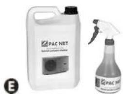
- Clean the outside of the appliance using a solvent-free product; a specific «PAC NET» cleaning kit is available as an accessory in the Zodiac catalogue for this purpose (see § "5.1 | Description").
3.2.3 Maintenance to be carried out by a qualified technician

- Please read the safety instructions before performing any of the maintenance operations described below, see "3.2.1 Safety instructions concerning appliances containing R32 refrigerant"
- Check that the control system is operating correctly.
- Check that the condensates flow correctly when the appliance is in operation.
- Check the safety mechanisms.
- Check the connection of the metal masses to the earth.
- Check that the electrical cables are correctly tightened and connected and that the switch box is clean.
Q
4 Troubleshooting

- If a problem occurs, before you contact your retailer, please carry out these few simple checks using the following tables.
- If the problem continues, contact your retailer.
• : Actions to be performed by a qualified technician only

4.1 I Appliance behaviour
| The appliance does not start heating straight away | When the setpoint temperature is reached, the heat pump stops heating: the water temperature is higher than or equal to the setpoint temperature.When the water flow rate is zero or is not enough, the heat pump stops: check that the water is circulating correctly in the heat pump (see § "2.2 I User interface presentation") and that the hydraulic connections are correct.The heat pump stops when the outdoor temperature falls below -12 °C.It may be that the heat pump has detected an operating fault (see § "4.2 I Error code display").If you have checked these points and the problem persists: contact your retailer. |
| The appliance is discharging water | Often called condensates. This water is the moisture contained in the air which condenses on contact with certain cold mechanisms in the heat pump, especially on the evaporator. The damper the air, the more condensates your heat pump will produce (your appliance may drain several litres of water per day). This water is retrieved by the base of the heat pump and drained by the condensate drainage elbow (see § "1.2 I Hydraulic connections").To check that the water is not coming from a leak in the pool circuit on the heat pump, shut down the heat pump and run the filtration pump for the water to circulate in the heat pump. If the water continues to flow through the condensate drainage lines, there is a water leak in the heat pump; contact your retailer. |
| The evaporator is iced over | Your heat pump will soon switch to its defrost cycle to melt the ice.If your heat pump cannot manage to defrost its evaporator, it will stop itself; this means that the outdoor temperature is too low (below -12 °C). |
| The appliance is "smoking" | The machine has come to the end of the defrost cycle; water has changed to gaseous state and passes through the grid.If your heat pump is not in its defrost cycle, this is not normal. Switch off and disconnect the heat pump immediately and contact your retailer. |
| The appliance is not working | If there is no display, check the supply voltage and the F2 fuse.When the setpoint temperature is reached, the heat pump stops heating: the water temperature is higher than or equal to the setpoint temperature.When the water flow rate is zero or is not enough, the heat pump stops: check that the water is circulating correctly in the heat pump (see § "2.2 I User interface presentation").The heat pump stops when the outdoor temperature falls below -12 °C or rises above +40 °C.It may be that the heat pump has detected an operating fault (see § "4.2 I Error code display"). |
| The appliance is working but the water temperature does not increase | Check that the automatic water filling controller (see diagram in § «2.3 I Operation») is not stuck in the open position: this will keep supplying cold water into the pool and will prevent the temperature from rising.There is too much heat loss. Install a heat insulated cover on your pool.The heat pump is unable to capture enough calories as its evaporator is clogged with dirt. Clean it to restore its performances (see § "3.2 I Maintenance").Check that the external environment is not hindering the heat pump (see § "1 Installation").Check that the heat pump is the right size for this pool and its environment. |
| The fan is running but the compressor stops from time to time with no error message | If the outdoor temperature is low, the heat pump performs defrost cycles under normal operation.The heat pump is unable to capture enough calories as its evaporator is clogged with dirt. Clean it to restore its performances (see § "3.2 I Maintenance"). |
| The appliance trips the circuit breaker | Check that the circuit breaker is correctly dimensioned and that the cable section used is appropriate (see § "5.2 I Technical specifications").The supply voltage is too low: contact your electricity supplier. |

4.2 I Error code display
| Display of Possible causes Solutions Reset | |||
| EO1Exchanger protection in "cooling" mode | ST4 sensor temperature too low | Wait until the exterior temperature rises | Automatic |
| EO2High temperature error on evaporator in "cooling" mode | ST3 sensor temperature over 60°C or evaporator scaled up | Clean the evaporator, if problem persists, call a qualified technician | Automatic if ST3 sensor temperature below 45 °C |
| EO3Phase order fault (on three phase models only) | Cabling not respected on the appliance's supply terminals, | Invert phases on power terminals (appliance switched off) | By electricity supply disconnection or by pressing |
| Electricity provider has changed the order of the phases | Contact the electricity provided to find out if your installation has been modified. | ||
| Temporary disconnection of the power supply to one or more phases | |||
| EO4Cooling circuit low pressure fault | Pressure fault in the low pressure circuit (if problem persists after resetting) | Call a qualified technician | • «Steady red» LED = automatic• «Flashing red» LED = press |
| EO5Cooling circuit high pressure fault | Exchanger clogged with dirt | Clean the water exchanger | • «Steady red» LED = automatic• «Flashing red» LED = press |
| Insufficient water flow | Increase flow using the bypass, check that the pool filter is not clogged | ||
| Air and water emulsion has passed into the appliance | Check the pool's hydraulic circuit | ||
| Flow switch is blocked | Check the flow switch | ||
| EO6Compressor discharge temperature fault | Compressor discharge temperature too high | Call a qualified technician | • «Steady red» LED = automatic• «Flashing red» LED = press |
| EO7ST1 sensor fault - water inlet sensor | Sensor is faulty or offline | Reconnect or change the sensor | By electricity supply disconnection or automatic if the fault disappears |
| EO8ST4 sensor fault - fluid line sensor | Sensor is faulty or offline | Reconnect or change the sensor | By electricity supply disconnection or automatic if the fault disappears |
| EO9ST3 sensor fault - Defrost sensor | Sensor is faulty or offline | Reconnect or change the sensor | By electricity supply disconnection or automatic if the fault disappears |
| E10ST2 sensor fault - air inlet sensor | Sensor is faulty or offline | Reconnect or change the sensor | By electricity supply disconnection or automatic if the fault disappears |
| E11ST5 sensor fault - compressor discharge sensor | Sensor is faulty or offline | Reconnect or change the sensor | By electricity supply disconnection or automatic if the fault disappears |
| E12Communication fault between the regulation board and the display board | Bad connection between the boards | Check the connectors on the link cable between the boards | • «Steady red» LED = automatic• «Flashing red» LED = press 🔒 |
| Board power supply fault | Check the boards' power supply | ||
| Faulty boards | Replace the boards | ||
| E13Condenser protection | ST1 sensor temperature too low | Wait until the water temperature rises (above 35°C) or switch to “Hot” mode if the appliance is in “Cooling” mode | Automatic |
4.3 I Lighting of LEDs on the printed circuit board
| LED1 LED2 | LED3 LED4 LED5 | ||||
| No errorsAppliance switched off | ● | ||||
| No errorsAppliance in operation | ● | ● | |||
| Error 01 | ● | ○ | |||
| Error 02 | ● | ○ | |||
| Error 03 | ● | ○ | ○ | ||
| Error 04 | ● | ○ | |||
| Error 05 | ● | ○ | ○ | ||
| Error 06 | ● | ○ | ○ | ||
| Error 07 | ● | ○ | ○ | ○ | |
| Error 08 | ● | ○ | |||
| Error 09 | ● | ○ | ○ | ||
| Error 10 | ● | ○ | ○ | ||
| Error 11 | ● | ○ | ○ | ○ | |
| Error 12 | ● | ○ | ○ | ||
| Error 13 | ● | ○ | ○ | ○ |
●: LED steadily lit
○: LED flashing
Empty: LED off
4.41 Wiring diagrams

Wiring diagrams are available at the end of the document see "Schémas électriques / Wiring diagrams / Schaltplan / Elektrischschema / Esquema eléctrico / Esquema eléctrico / Schema elettrico"

⑤ Characteristics
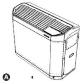
5.1 | Description
natural_image
Line drawing of a rectangular electronic device with ventilation grilles and a label (A) and asterisk (*) below, no readable text or symbols on the device itself.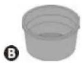
©
D
*In the appliance's box
natural_image
Two different chemical products: a white plastic container labeled 'PAC NET' and a spray bottle with a spray nozzle (no visible text or symbols on the main objects)| A | Z400iQ | |
| B Winterizing cap (x2) | ||
| C ∅50 connector to be glued (x2) | ||
| D | Winterizing cover | |
| Heating priority | ||
| E | PAC NET(cleaning product) | |
: supplied
+: available as an accessory
5.2 I Technical specifications
| Z400iQ MD4 MD5 MD7 TD7 MD8 TD8 MD9 TD9 | |||||||||
| Operating temperatures | air -12 to 40 °C -12 to 38 °C -12 to 35 °C | ||||||||
| water 15 to 32°C | |||||||||
| Defrosting by forced air circulation T°C air >10°C | |||||||||
| Defrosting by cycle inversion T°C air <10°C | |||||||||
| Voltage 220-240V / 1 / 50 Hz | 380-415V/3/50 Hz | 220-240V/1/50 Hz | 380-415V/3/50 Hz | 220-240V/1/50 Hz | 380-415V/3/50 Hz | ||||
| Admissible variation in voltage ± 10% | |||||||||
| Nominal absorbed intensity* | A | 6,9 | 10,1 | 13,9 | 6,1 | 16,2 | 7,7 | 19,4 | 8,5 |
| Maximum current input | A | 10 | 15 | 18,2 | 7,4 | 26 | 9,2 | 35,2 | 11,4 |
| Minimum cable section** | mm2 | 3 x 2,5 | 5 x 2,5 | 3 x 6 | 5 x 2,5 | 3 x 6 | 5 x 2,5 | ||
| 3G2,5 | 5G2,5 | 3G6 | 5G2,5 | 3G6 | 5G2,5 | ||||
| Proof pressure | bar | 2 | |||||||
| Service pressure | bar | 1,5 | |||||||
| Head loss | mCE | 1,4 | 1,5 | 1,5 | 1,5 | 1,1 | 1,1 | 1,1 | 1,1 |
| Medium water flow | m3/h | 4 | 5 | 6 | 7 | 8 | |||
| Sound pressure (db(A)) | Boost | 64 | 65 | 66 | 68 | 64 | 65 | 64 | 66 |
| Silence | 61 | 63 | 63 | 66 | 61 | 62 | 62 | 63 | |
| Frequency band | GHz | 2,412 - 2,484 | |||||||
| Emitted power | dBm | +20 | |||||||
| Type of refrigerant | R32 | ||||||||
| Refrigerant amount | kg | 0,87 | 1,05 | 1,45 | 1,18 | 1,80 | 1,59 | 1,80 | 1,59 |
| Net weight | kg | 70 | 71 | 90 | 81 | 105 | 97 | 110 | 97 |
The appliances have an Ingress Protection (IP) rating of IP24. Please refer to the marking indicating the IP-rating on your particular product.
* Rated values measured in "Heating" mode according to EN 14511
** Values provided for information purposes for a maximum length of 20 metres (calculation base: NFC 15-100), must be checked and adapted to the installation conditions and standards of the installation country.
• Maximum operating pressure of the refrigerant circuit: 4.2 MPa / 42 bar
• Minimum operating pressure of the refrigerant circuit: 0.05 MPa / 0.5 bar
• Maximum operating pressure of the water circuit: 0.3 MPa / 3 bar
• Minimum operating pressure of the water circuit: 0.05 MPa / 0.5 bar
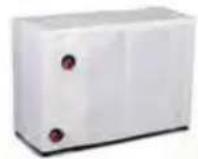
5.3 | Dimensions and marking
| Z400iQ | MD4 | MD5 | MD7 | TD7 | MD8 | TD8 | MD9 | TD9 |
| A* | 1030 | 1145 | ||||||
| B* | 450 | 480 | ||||||
| C* | 479 | 509 | ||||||
| D* | 880 | 1027 | ||||||
*Overall dimensions in mm
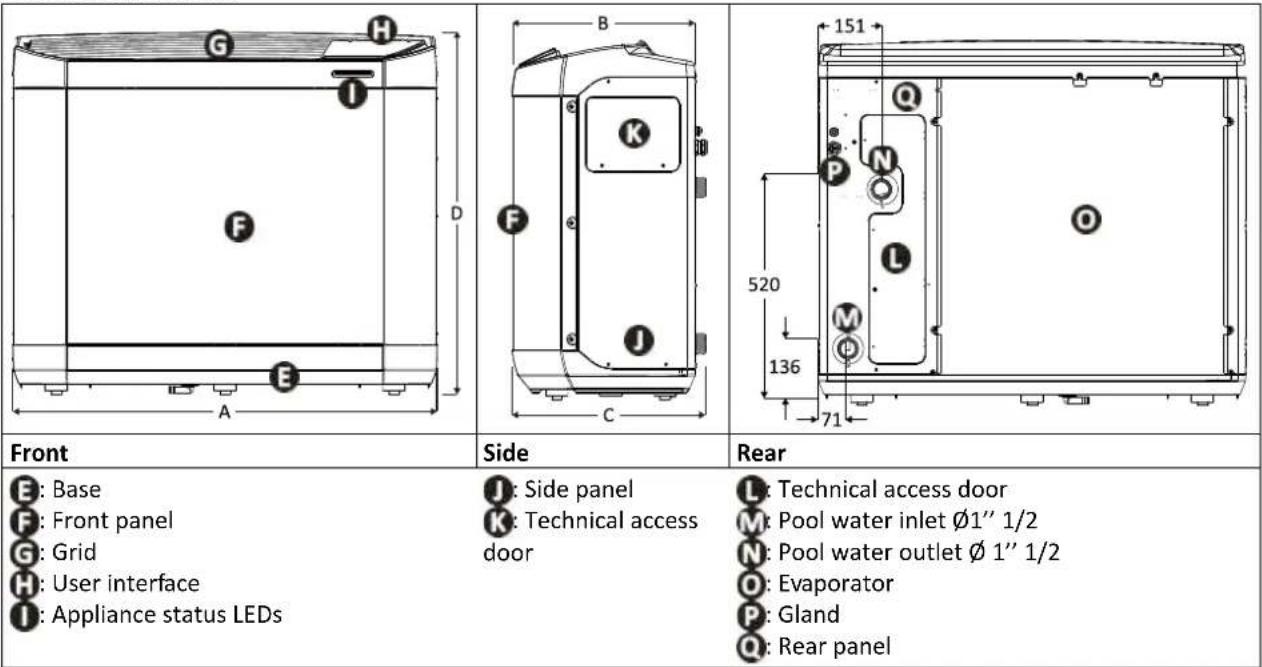
| Front | Side | Rear |
| E: BaseF: Front panelG: GridH: User interfaceI: Appliance status LEDs | J: Side panelK: Technical access door | L: Technical access doorM: Pool water inlet 1'' 1/2N: Pool water outlet 1'' 1/2O: EvaporatorP: GlandQ: Rear panel |

WARNHINWEISE

natural_image
Illustration of two people pulling a cart with legs attached, no text or symbols present
natural_image
Technical line drawing of a device with a screwdriver and a plus symbol, no text or labels presentnatural_image
Technical line drawing of a mechanical device casing with internal components (no text or symbols)natural_image
Illustration of a hand using a tool to adjust internal components on a circuit board (no text or symbols visible)2

natural_image
Diagram of a mechanical assembly with a tool inserted, showing internal components and no visible text or symbols.A: Wasserzulaufventil
B: Bypassventil
©: Wasserrücklaufventil
D: Wasserzulaufregelventil (optional)
E: Wasserrücklaufregelventil (optional)

natural_image
Line drawing of a rectangular electronic device with ventilation grilles and mounting brackets (no text or symbols)
©

natural_image
Two chemical products: a white container labeled 'PAC NET' and a spray bottle with a black spray nozzle (no visible text or symbols on the main objects)ALGEMENE WAARSCHUWINGEN
WAARSCHUWINGEN MET BETREKKING TOT ELEKTRISCHE APPARATEN
natural_image
Illustration of two people pulling a table with legs attached, no text or symbols presentA: Hijsband
natural_image
Technical line drawing of a device with screwdriver and mechanical components (no text or symbols)natural_image
Technical line drawing of a device casing with internal components and mounting holes (no text or symbols)natural_image
Diagram of a mechanical component with a tool inserted, showing internal parts and a magnified view (no text or symbols)2
natural_image
Diagram of a mechanical assembly with a tool interacting with a component, showing internal parts and no text or symbols.natural_image
Illustration of two people pulling a cart with legs attached, no text or symbols presentA: Correa
1.2 | Conexiones hidráulicas
natural_image
Technical line drawing of a device with screwdriver and tool, no text or symbols present2

natural_image
Technical line drawing of a device casing with internal components and mounting holes (no text or symbols)natural_image
Diagram of a mechanical component with a tool inserted, showing internal parts and a magnified view (no text or symbols)2

natural_image
Diagram of a mechanical assembly with a tool interacting with a component (no text or symbols visible)natural_image
Illustration of two people pulling a cart with legs attached, no text or symbols presentA: Cinta
natural_image
Technical line drawing of a mechanical device with a screwdriver inserted, showing internal components and alignment arrows (no text or symbols)②
natural_image
Technical line drawing of a device casing with internal components and mounting holes (no text or symbols)natural_image
Diagram of a mechanical component with a tool inserted, showing internal parts and a magnified view (no text or symbols)2
natural_image
Diagram of a mechanical assembly with a tool interacting with a component, showing internal structure and no text or symbols.
A: válvula de entrada de água
B: válvula de by-pass
C: válvula de saída de água
D: válvula de ajuste da entrada de água (facultativa)
E: válvula de ajuste da saída de água (facultativa)

natural_image
Line drawing of a rectangular electronic device with ventilation grilles and mounting brackets (no text or symbols)
©

natural_image
Two chemical products: a white container labeled 'PAC NET' and a spray bottle with a black tip (no visible text or symbols on the main objects)natural_image
Illustration of two people pulling a table with legs, no text or symbols presentA: Cinghia
natural_image
Technical line drawing of a device with screwdriver and tool, no text or symbols present2

natural_image
Technical line drawing of a device casing with internal components and mounting holes (no text or symbols)natural_image
Diagram of a mechanical assembly with tool and component, no visible text or symbols2

natural_image
Diagram of a mechanical assembly with a tool interacting with a component, showing internal parts and no text or symbols.IT
natural_image
Line drawing of a rectangular electronic device with ventilation grilles and mounting brackets (no text or symbols)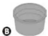
©
natural_image
Two chemical products: a white container labeled 'PAC NET' and a spray bottle with a black tip (no visible text or symbols on the main objects)natural_image
Illustration of two people carrying a large cart with arms extended, no text or symbols presentA: Ιμάντας
natural_image
Technical line drawing of a device with screwdriver and mechanical components (no text or symbols)natural_image
Technical line drawing of a mechanical device casing with internal components (no text or symbols)natural_image
Illustration of a hand using a tool to inspect internal components (no text or symbols visible)2

natural_image
Diagram of a mechanical assembly with a tool inserted, showing internal components and no visible text or symbols.
natural_image
Line drawing of a rectangular electronic device with ventilation grille and mounting bracket (no text or symbols)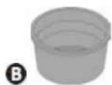
©
natural_image
Two chemical products: a white container labeled 'PAC NET' and a spray bottle with a black tip (no visible text or symbols on the main objects)Europe:
www.zodiac.com

Australia:
www.zodiac.com.au
See warranty details on :


- | Raccordements hydrauliques
- Read the instructions in this manual carefully before using the device.
- The appliance contains R32.
- GENERAL WARNINGS
- WARNINGS ASSOCIATED WITH ELECTRICAL APPLIANCES
- WARNINGS CONCERNING APPLIANCES CONTAINING REFRIGERANT
- WARNINGS CONCERNING APPLIANCES CONTAINING R32 REFRIGERANT
- INSTALLATION AND MAINTENANCE
- TROUBLESHOOTING
- LABELLING
- RECOVERING
- Recycling
- CONTENTS
- Installation 6
- ② Use 11
- Maintenance 16
- Troubleshooting
- Characteristics
- Tip: to make it easier to contact your retailer
- Installation
- I Selecting the location
- Tip: reduce any noise annoyance from your heat pump
- Setting up the device
- | Hydraulic connections
- Tip: condensate drainage
- | Accessing the electrical connection terminal boards
- | Power connections
- Wiring on a spring-cage terminal block
- | Connecting options
- "Heating priority" option
- Remote "on/off" control option
- | Operating principle
- General operation
- Tip: improve your pool's temperature rise and maintenance
- Operating modes (default settings)
- Precautions
- | User interface presentation
- Presentation of the display screen and function keys
- Description of the display screen
- Description of the LEDs showing the «appliance status»
- | Operation
- - An incorrect by-pass setting may cause the heat pump to malfunction.
- I User functions
- Locking/unlocking the keyboard
- Adjusting the temperature setpoint
- Activating/deactivating "silence" mode
- 1st method
- 2nd method
- Activating/deactivating "cold" mode
- I Connection to the iAquaLink™ app
- ③ Maintenance
- | Winterizing
- | Maintenance
- Safety instructions concerning appliances containing R32 refrigerant
- Area check
- Work procedure
- General work area
- Check for the presence of refrigerant
- Check for the presence of a fire extinguisher
- No source of ignition
- Area ventilation
- Refrigeration equipment check
- Electrical component check
- Repair of insulated components
- Repair of intrinsically safe components
- Wiring
- Detection of flammable refrigerant
- Removal and discharge
- Loading procedures
- Dismantling
- User maintenance
- Maintenance to be carried out by a qualified technician
- Q
- I Appliance behaviour
- I Error code display
- I Lighting of LEDs on the printed circuit board
- Wiring diagrams
- ⑤ Characteristics
- | Description
- I Technical specifications
- | Dimensions and marking
- WARNHINWEISE
- ALGEMENE WAARSCHUWINGEN
- WAARSCHUWINGEN MET BETREKKING TOT ELEKTRISCHE APPARATEN
- | Conexiones hidráulicas
Brand : ZODIAC
Model : Z400 iQ
Category : Heating