
CLP446e - Talkie Walkie MOTOROLA - Free user manual and instructions
Find the device manual for free CLP446e MOTOROLA in PDF.

| Product type | Professional walkie-talkie |
| Brand | Motorola Solutions |
| Model | CLP446e |
| Category | PMR446 walkie-talkie |
| Frequency band | PMR446 (446.0 – 446.2 MHz) |
| Number of channels | 16 (8 by default, 8 additional via CPS) |
| Transmission power | 0.5 W |
| Power supply | Rechargeable Li-Ion battery (included) |
| Battery life | Up to 20 hours (standard 5/5/90 cycle) |
| Charging time | Approximately 5.5 h (single unit charger) / 4 h (multi-unit charger) |
| Typical range | Up to 6 levels (building) or 7,400 m² |
| Protection rating | IP54 (with cover or audio accessory connected) |
| Main functions | Channel selection, scanning, monitor, call tone, call reminder, programming via CPS, cloning, CTCSS/DPL interference reduction |
| Display | Smart ring LED indicator (16 colors per channel) |
| Accessory connector | Wired audio jack (with locking) |
| Box contents | Radio, Li-Ion battery, battery cover, charger with power adapter, case with belt clip, audio accessory, jack cover, quick start guide, safety documentation |
| Dimensions | Not specified in the manual |
| Weight | Not specified in the manual |
| Maintenance and cleaning | Clean with a soft cloth; do not immerse in water, do not use alcohol or detergents |
| Safety | RF exposure: professional use, follow safety instructions; acoustic: use the lowest possible volume; battery: charge only with approved Motorola Solutions chargers |
| Spare parts and repairability | Available accessories (batteries, chargers, cases, programming/cloning cables); repair by a Motorola Solutions certified technician |
| Warranty | Motorola Solutions limited warranty (see manual for details) |
Frequently Asked Questions - CLP446e MOTOROLA
User questions about CLP446e MOTOROLA
0 question about this device. Answer the ones you know or ask your own.
Ask a new question about this device
Download the instructions for your Talkie Walkie in PDF format for free! Find your manual CLP446e - MOTOROLA and take your electronic device back in hand. On this page are published all the documents necessary for the use of your device. CLP446e by MOTOROLA.
USER MANUAL CLP446e MOTOROLA
CLP446e/CLPe PLUS User Guide
Contents
Documentation Copyrights 4
Disclaimer 5
Computer Software Copyrights 6
Batteries, Chargers, and Audio Accessories Safety Information. 7
Operational Safety Guidelines. 7
Acoustic Safety 8
Radio Frequency Exposure Safety Standards 9
Notice to Users 10
Introduction 11
Package Content. 11
Chapter 1: Radio Overview. 12
Chapter 2: Getting Started. 13
2.1 Installing the Battery. 13
2.2 Connecting Wired Audio Accessory 13
2.3 Turning the Radio On or Off 15
2.4 Adjusting the Volume 15
2.5 Inserting and Removing the Swivel Belt Clip Holster 15
2.6 Transmitting and Receiving 16
2.6.1 Talk Range 17
2.7 Menu Setting 17
2.7.1 Operations Using Menu Settings 17
2.8 Selecting Channels 18
2.8.1 Default Channel Settings for CPS 18
2.8.2 LED Indicators 20
2.8.2.1 Volume LED 20
2.9 Monitoring Channels 21
2.10 Scan. 21
2.10.1 Scanning Radio Channels 21
2.11 Dynamic Talkaround Scan 21
2.12 Sending Call Tones 22
2.13 Muting the Radio 22
2.14 Escalate Call 22
Chapter 3: Battery and Charger. 23
3.1 Battery Specifications 23
3.2 Battery Life 23
3.3 Removing the Li-Ion Battery 23
3.4 Power Supply, Adapter, and Drop-in Tray Charger 24
3.5 Stand-Alone Battery 25
3.5.1 Charging a Stand-Alone Battery with the Drop-in Tray SUC 25
3.5.2 Charging a Stand-Alone Battery with the Drop-in Tray MUC- Optional Accessory 25
3.5.3 Estimated Charging Time 26
3.6 Charging Radio with the Drop-in Tray SUC 26
3.7 Charging with the Drop-In Tray MUC-Optional Accessory 26
3.8 Charger LED Indications 27
3.9 Checking Battery Status 28
Chapter 4: Radio Programming through CPS. 29
4.1 Programming the Radio 29
4.2 Factory Default Settings 30
Chapter 5: Radio Cloning. 33
5.1 Cloning Radio Settings 33
5.2 Cloning Radios using the Cloning Cable 33
5.3 Cloning Radios using the Multi-Unit Charger 34
5.4 Troubleshooting Cloning Mode 35
Chapter 6: Advanced Radio Configuration 36
6.1 Entering Advanced Radio Configuration Mode 36
Chapter 7: Troubleshooting 37
7.1 Symptom and Solutions 37
Chapter 8: Use and Care. 40
Chapter 9: Radio Frequency and Code Chart. 41
9.1 CLP446e Frequency List 41
9.2 CLPe PLUS Frequencies 42
9.3 CTCSS/DPL Interference Eliminator Codes 43
Chapter 10: Motorola Solutions Limited Warranty. 46
10.1 Warranty Information 46
10.2 V. WHAT THIS WARRANTY DOES NOT COVER 46
Chapter 11: Accessories 47
Documentation Copyrights
No duplication or distribution of this document or any portion thereof shall take place without the express written permission of Motorola Solutions.
No part of this manual may be reproduced, distributed, or transmitted in any form or by any means, electronic or mechanical, for any purpose without the express written permission of Motorola Solutions.
Disclaimer
The information in this document is carefully examined, and is believed to be entirely reliable. However, no responsibility is assumed for inaccuracies.
Furthermore, Motorola Solutions reserves the right to make changes to any products herein to improve readability, function, or design. Motorola Solutions does not assume any liability arising out of the applications or use of any product or circuit described herein; nor does it cover any license under its patent rights, nor the rights of others.
Computer Software Copyrights
The Motorola Solutions products described in this manual may include copyrighted Motorola Solutions computer programs stored in semiconductor memories or other media. Laws in the United States and other countries preserve for Motorola Solutions certain exclusive rights for copyrighted computer programs, including, but not limited to, the exclusive right to copy or reproduce in any form the copyrighted computer program. Accordingly, any copyrighted Motorola Solutions computer programs contained in the Motorola Solutions products described in this manual may not be copied, reproduced, modified, reverse-engineered, or distributed in any manner without the express written permission of Motorola Solutions.
Furthermore, the purchase of Motorola Solutions products shall not be deemed to grant either directly or by implication, estoppel, or otherwise, any license under the copyrights, patents or patent applications of Motorola Solutions, except for the normal non-exclusive license to use that arises by operation of law in the sale of a product.
Batteries, Chargers, and Audio Accessories Safety Information
This document contains important safety and operating instructions. Read these instructions carefully and save them for future reference. Before using the battery charger, read all the instructions and cautionary markings on:
the charger
the battery
- the radio attached with battery
1 To reduce risk of injury, charge only the rechargeable Motorola Solutions-authorized batteries. Charging the other batteries may cause explosion, personal injury, and damage.
2 Use of accessories not recommended by Motorola Solutions may result in fire, electric shock, or injury.
3 To reduce damage to the electric plug and cord, pull by plug rather than the cord when disconnecting the charger.
4 An extension cord should not be used unless necessary. Use of an improper extension cord may result in fire and electric shock. If an extension cord must be used, make sure that the cord size is 18 AWG for lengths up to 2.0m (6.5 feet), and 16 AWG for lengths up to 3.0m (9.8 feet).
5 Do not operate the charger if it has been broken or damaged in any way. Take it to any qualified Motorola Solutions service representatives.
6 Do not disassemble the charger; it is not repairable and replacement parts are not available. Disassembly of the charger may result in risk of electrical shock or fire.
7 To reduce risk of electric shock, unplug the charger from the AC outlet before attempting any maintenance or cleaning.
Operational Safety Guidelines
- Turn off the radio while charging.
- The charger is not suitable for outdoor. Use only in dry locations or conditions.
- Connect charger to an appropriately fused and wired supply of the correct voltage (as specified on the product only).
- Disconnect charger from line voltage by removing main plug.
- Connect the equipment to an outlet which is easy to access and near.
- For equipment using fuses, replacements must comply with the type and rating specified in the equipment instructions.
Maximum ambient temperature around the power supply equipment must not exceed 40^ (104 F). - Power output from the power supply unit must not exceed the ratings stated on the product label located at the bottom of the charger.
- Make sure the cord is not stepped on, tripped over, subjected to water, damage, or stress.
Acoustic Safety

CAUTION: Exposure to loud noises from any source for extended periods of time may temporarily or permanently affect your hearing. The louder the radio volume, the less time is required before your hearing can be affected. Hearing damage from loud noises is sometimes undetectable at first and can have a cumulative effect.
To protect your hearing:
- Use the lowest volume necessary to do your job.
- Increase the volume only if you are in noisy surroundings.
- Reduce the volume before connecting headset or earpiece.
- Limit the amount of time you use headsets or earpieces at high volume.
- If you experience hearing discomfort, ringing in your ears, or speeches that are muffled, you should stop listening to your radio through your headset or earpiece, and have your hearing checked by your doctor.
Radio Frequency Exposure Safety Standards
Product Safety and RF Exposure Compliance.

CAUTION:
Before using the radio, read the operating instructions for safe usage contained in the Product Safety and RF Exposure booklet contained with your radio.
ATTENTION!
This radio is restricted to Occupational use only to satisfy FCC RF energy exposure requirements. Before using the radio, read the RF Energy Exposure and Product Safety Guide for Portable Two-Way Radios which contains important operating instructions for safe usage and RF energy awareness and control for Compliance with applicable standards and Regulations.
For a list of Motorola Solutions-approved antennas, batteries, and other accessories, visit the following website:
http://www.motorolasolutions.com/CLPe
Notice to Users
This device complies with Part 15 of the FCC rules per the following conditions:
- This device may not cause harmful interference.
This device must accept any interference received, including interference that may cause undesired operation. - CAUTION: Changes or modifications made to this device, not expressly approved by Motorola Solutions, could void the authority of the user to operate this equipment.
Introduction
This user guide covers the operation of your radios.
Your dealer or system administrator may have customized your radio for your specific needs. Check with your dealer or system administrator for more information.
You can consult your dealer or system administrator about the following:
- Is your radio programmed with any preset conventional channels?
- Which buttons have been programmed to access other features?
- What optional accessories may suit your needs?
- What are the best radio usage practices for effective communication?
- What maintenance procedures that helps promote longer radio life?
Package Content
This section provides information regarding package content for the radio.
Your product package contains the following products and manuals:
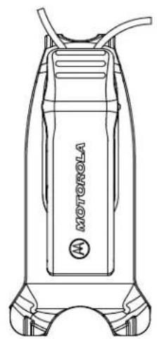
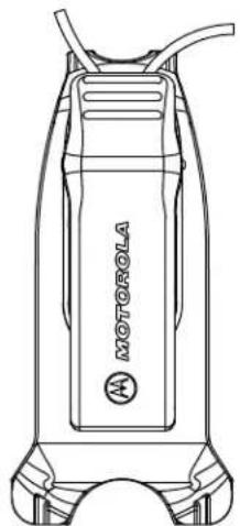
- CLPe Series Two-way Radio
- Swivel Belt Clip Holster
Lithium-Ion Battery and Battery Door - Drop-In Tray Charger with Transformer 1
Audio Accessory
Audio Jack Cover - Quick Start Guide, RF Safety Booklet, RED Leaflet
For product information, refer to https://learning.motorolasolutions.com.
This user guide covers the following models:
| Model Frequency Band | Transmit Power Repeater Compatibility | No. of Channels3 |
| CLP446e PMR4 46 0.5 W No 16 | 4 | |
| CLPe PLUS UHF 1 W Yes 16 |
Chapter 1
Radio Overview
This chapter explains the buttons and functions of the radio.
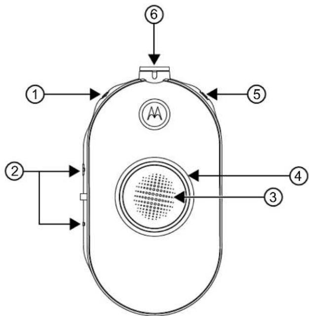
Figure 1: Radio Controls
| Item Number Description | |
| 1 Power and Battery button | |
| 2 Volume Control (+/-) and Mute button | |
| 3 Push-to-Talk (PTT) button | |
| 4 Smart Status Glow Ring | |
| 5 Menu button | |
| 6 Accessory Connector |
Chapter 2
Getting Started
This section helps you to get familiar with the basic operations of the radio.
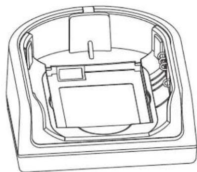
2.1
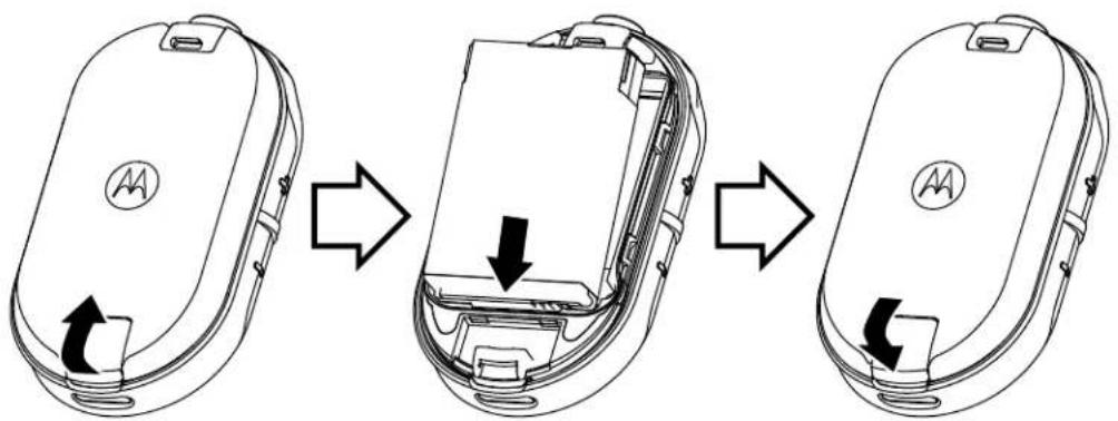
Installing the Battery
Procedure:
1 At the bottom of the battery door, lift the latch up and remove the battery door of the radio.
2 Align the battery contacts to the tabs of the battery compartment.
3 Insert the end with the battery contacts before pressing the battery down to secure in place.
4 Place the battery door on the radio and push the latch down to lock the battery door.

Figure 2: Battery Installation
2.2
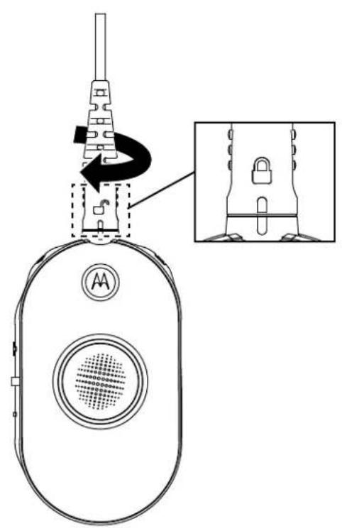
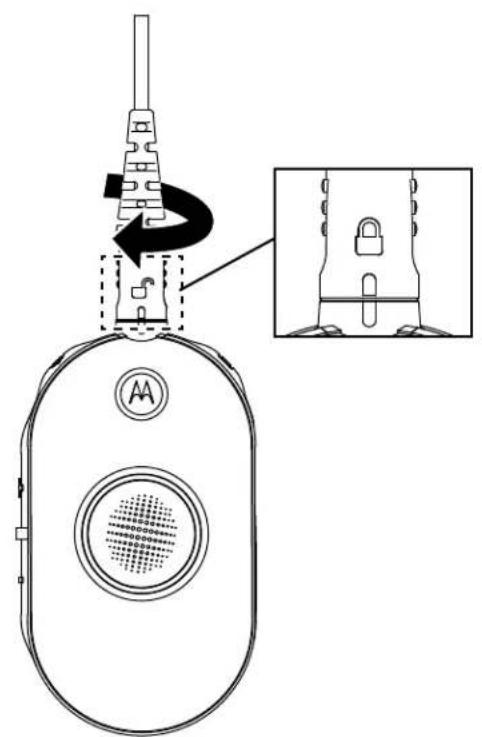
Connecting Wired Audio Accessory
Prerequisites: Turn the radio off.
Procedure:
1 Plug the audio accessory into the radio with the unlock icon on the audio accessory facing the front of the radio.
Ensure the indicator on the audio accessory and the radio is aligned.
2 Turn the audio accessory plug until the lock icon on the plug is facing the front of the radio and the indicators are aligned.

Figure 3: Connecting Wired Audio Accessory
3 Turn the radio on.
4 Press either the Battery Status, Menu, or Volume Control button to check for audio through the audio accessory.
Table 1: Top LED Configuration if Wired Audio Accessory is not Connected or Removed
| User Mode LED Status Color | ||
| Turn on radio without an audio accessory plugged in. | Solid Blue | |
| Audio accessory removed while radio is on. | Red/purple blinks until an audio accessory is plugged in |

NOTICE:
Lower the radio volume before placing the audio accessory in or near your ear.
The CLPe Series radios offer various audio accessories. For detailed audio accessories list, refer to http://www.motorolasolutions.com/CLPe for information on approved accessories.
2.3
Turning the Radio On or Off
Procedure:
1 To turn on the radio, press and hold the Power and Battery button until you hear a short tone and the Smart Status Glow Ring illuminates.
2 To turn off the radio, press and hold the Power and Battery button until you hear a short tone and the Smart Status Glow Ring indicator blinks once.
2.4
Adjusting the Volume
Procedure:
1 To increase the volume, press the (+) button.

NOTICE: Radio has 15 increments of volume.
2 To decrease the volume, press the (-) button.
2.5
Inserting and Removing the Swivel Belt Clip Holster
The radios offer various flexible carrying accessories. For Motorola Solutions approved accessories list, refer to http://www.motorolasolutions.com/CLPe.
Procedure:
1 To insert the radio into the holster, perform the following steps:
a Slide the bottom of the radio into the holster.
b Snap the top of the holster into the radio around the accessory connector.
2 To remove radio from the holster, pull either the top or bottom tab and pull the radio from the holster.
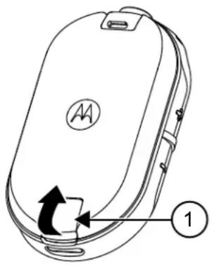
3 Make a small loop in the cord and pass the cord through the cord guide. Nest the cord in the U-shaped groove and pull tight to lock the cord in place.
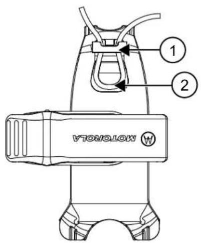
Figure 4: Swivel Belt Clip Holster
| Item Number Description | |
| 1 Cord Guide | |
| 2 U-Shaped Groove |
4 Turn the belt clip to the position as needed.
2.6
Transmitting and Receiving
Procedure:
1 To transmit calls, perform one of the following actions:
- Press and hold the PTT button on the front of the radio.
- Press and hold the PTT button on the wired audio accessory with the inline PTT button.
2 Speak clearly into the microphone on the audio accessory.
3 Release the PTT button to listen.
4 To receive calls, listen through the earpiece and press the PTT button to respond.
2.6.1
Talk Range
Table 2: Talk Range
| Model Application Range | (Tipi- | cal Cover- age) | Range |
| CLP446e Unit to Unit Up | to 6 floors Up to 80,000 ft | 2 (7,400 m2) | |
| CLPe PLUS Unit to Unit | Up to 10 floors Up to 100,000 ft | 2 (9,200 m2) | |
| With Repeater | Up to 20 floors | Up to 250,000 ft2 (23,200 m2) |
2.7
Menu Setting
Procedure:
1 To navigate through the menu settings, press the Menu button.
2 To exit the menu, short press the PTT button or wait for three seconds.
2.7.1
Operations Using Menu Settings
This section explains operations using the menu settings.

NOTICE:
It is not necessary to wait for the voice prompt to be completed before continuing with pressing the next button.
If you are in the menu mode, short press PTT or wait 3 seconds to exit the menu.
Procedure:
1 Changing channel:
a Press Menu button to navigate to Channel.
b Press the (+) or the (-) button to change channel.
2 Entering Monitor Mode:
a Press Menu button to navigate to Monitor.
b Press the (+) to activate or the (-) button to deactivate monitor.
3 Entering Scan Mode:
a Press Menu button to navigate to Scan.
b Press the (+) to activate or the (-) button to deactivate scan.
4 Sending Call Tone:
a Press Menu button to navigate to Call Tone.
b Press the (+) or the (-) button to send call tone.
Enabled through Customer Programming Software (CPS).
2.8
Selecting Channels
Procedure:
1 Press the Menu button.
You hear a voice prompt to change channel by pressing the (+) or (-) button.
2 Select the required channel.
The LED indicates the color of the new channel.
3 Press the PTT button to confirm or the channel is activated after three seconds hang time.
2.8.1
Default Channel Settings for CPS
The table describes the default channel settings for Customer Programming Software (CPS).
Table 3: Channel Settings for CPS
| CLP446e5 Models and CLPe PLUS Models | ||
| Channel LED Status Color | ||
| 1 Red | ||
| 2 Green | ||
| 3 Yellow | ||
| 4 Blue | ||
| 5 Purple | ||
| 6 White | ||
| 7 Aqua | ||
| 8 Orange | ||
| 9 Red | White | |
| 10 Green | White | |
| 11 Yellow | White | |
| 12 Blue | White | |
| 13 Purple | White | |
| 14 White | White | |
| 15 Aqua | White | |
| 16 Orange | White | |
| NOTICE: Channel 9 to 16 is enabled through Customer Programming Software (CPS) configuration. | ||
2.8.2
LED Indicators
| Feature LED Indicator | |
| Monitor mode Solid per channel color. | |
| Call tone Momentary solid per channel | color. |
| Scan Cycles through in clockwise direction with one LED lighting up at one time. LED color changes on the top slot when each cycle is completed. | |
| Turn on or off Top red and the remaining white LED illuminates briefly. | |
| Advanced radio configuration Blinking | green. |
| Audio jack feedback LED blinks blue | when no accessory at power-up. LED blinks red and purple fast alternatively when accessory is unplugged. |
2.8.2.1
Volume LED
When volume is increased, Smart Status Glow Ring LED lights up in a clockwise direction from the bottom left to the bottom right of the LED ring.
The followings are the three levels of LED brightness for each LED when volume is increased:
Dim
Medium
Maximum brightness
2.9
Monitoring Channels
Procedure:
1 To activate the monitor selection mode, press the Menu button and navigate to Monitor Selection.
If the monitor is off, you hear a voice prompt to activate the monitor mode by pressing the + or - button.
2 Press + or - button to activate or deactivate the monitor mode.
When the monitor mode is on, you hear static if no activity is present or audio if channel activity is present.
3 To engage the monitor mode, enable monitor through the menu and let the menu time out.
4 To exit the Monitor mode, press the PTT button.
2.10
Scan
You can scan up to 16 channels on CLP446e and CLPe PLUS models.
When the radio detects activity, it stops scanning and locks in on the active channel. This allows you to listen and talk to the person transmitting without changing channels.
2.10.1
Scanning Radio Channels
Procedure:
1 To navigate to Scan mode, press the Menu button.
If the scan is off, you hear a voice prompt to activate Scan by pressing the+ or - button.
2 To activate scan, press + or - button.
When scan is on, you hear a voice prompt to deactivate Scan by pressing the + or - button.
3 To deactivate scan, press + or - button.
2.11
Dynamic Talkaround Scan
This feature maximizes communication coverage for an on-site repeater enabled on two way radio systems.
Dynamic Talkaround Scan is enabled on a repeater channel through the Customer Programming Software (CPS). The feature gives the radio the ability to scan the transmit and receive frequencies of a repeater channel.

NOTICE: The feature is given higher priority than the scan mode. If the Dynamic Talkaround Scan and Scan are enabled on the home channel, then the radio can only support the Dynamic Talkaround Scan. This feature is only available in CLPe PLUS model.
2.12
Sending Call Tones
Procedure:
1 To navigate to Call Tone, press the Menu button.
2 To transmit a selected call tone, press + or -.

NOTICE:
Six call tones are available.
This feature is enabled through Customer Programming Software (CPS).
2.13
Muting the Radio
The Mute Headset Volume setting is configured through Customer Programming Software (CPS).
Procedure:
1 To lower or mute the headset volume, press and hold + or - button.
You hear a "Mute" voice prompt from the radio.
2 To unmute the headset volume, press any buttons.
You hear a "Unmute" voice prompt from the radio.
2.14
Escalate Call
Escalate Call feature allows you to switch to Escalate Call Channel and send call tone on the Escalate Call Channel.
To enable the Escalate Call feature, Escalate Call Channel must be configured in Customer Programming Software (CPS). Long press menu button activates the Escalate Call feature and automatically send Escalate Call Tone on Escalate Call Channel. The Escalate Call Hangtime starts after every call ends. Radio stays in Escalate Call Hangtime for a predefined period. Escalate Call ends when the hangtime expires and radio returns to the previous channel. The hangtime is configured through CPS.
Pressing the PTT button during Escalate Call Hangtime allows you to talk on the channel. Escalate Call Hangtime restarts after the voice call is ended and you can receive calls from other radios on the Escalate Call Channel.
Your radio follows the selected channel behavior except the call tone and no channel announcement upon switching to Escalate Call Channel. The call tone is configured through CPS by selecting one of the six call tones.
To exit Escalate Call Channel before hangtime expires, short press either On, Off, Menu button, or long press Menu button.
Chapter 3
Battery and Charger
This chapter describes the battery and charger feature for the radio.
3.1
Battery Specifications
The radio comes equipped with a rechargeable Li-1on battery. To ensure optimum capacity and performance, the battery should be charged before initial use.
Battery life is determined by several factors. The critical ones are overcharging of batteries and the average depth of discharge each cycle. Typically, the greater the overcharge and the deeper the average discharge, the fewer cycles a battery lasts. For example, a battery which is overcharged and discharged 100% for several times a day, lasts fewer cycles than a battery that overcharges less and is discharged to 50% per day. Battery with minimal overcharge and has an average of 25% discharge, lasts even longer.
Motorola Solutions batteries are designed specifically to be used with a Motorola Solutions charger and vice versa. Charging batteries with non-Motorola Solutions equipment may lead to battery damage and void the battery warranty. Whenever possible, maintain the battery temperature to 77^ (25^) (room temperature). Charging a cold battery (below 50^ [10^] ) may result in leakage of electrolyte and ultimate failure of the battery. Charging a hot battery (above 95^ [35^] ) results in reducing discharge capacity and affecting the performance of the radio. Motorola Solutions rapid-rate battery chargers contain a temperature-sensing circuit to ensure that batteries are charged within the temperature limits.
3.2
Battery Life
The following table specifies the battery life based on 5% transmit, 5% receive, and 90% standby (standard duty cycle).
Table 4: Estimated Battery Life
| Model Estimated Battery Life | |
| CLP446e 20 hours | |
| CLPe PLUS 18 hours |
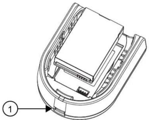
3.3
Removing the Li-ON Battery
Prerequisites: Ensure the radio is turned off.
Procedure:
1 At the bottom of the battery door, lift the latch up and remove the battery door of the radio.
2 Pull the battery away from the radio.
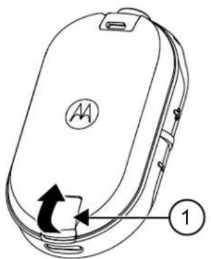
Figure 5: Battery Removal
| Item Number Description | |
| 1 Battery Latch |
3.4
Power Supply, Adapter, and Drop-in Tray Charger
The radio is packaged with one Drop-in Tray Charger with a transformer.

NOTICE: Applicable to non-multipack models only.
For information on accessories, see Accessories on page 47.
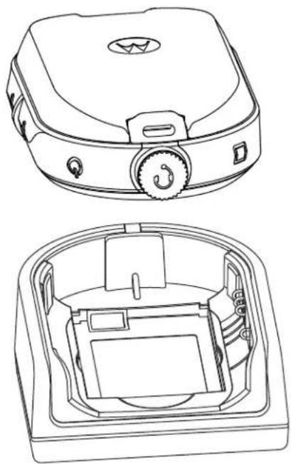
Figure 6: Power Supply, Adapter, and Drop-in Tray Charger
3.5
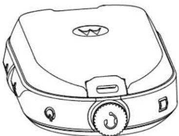
Stand-Alone Battery
The battery can be charged as a stand-alone battery.
The battery is charged by using either a Single Unit Charger (SUC) or a Multi-Unit Charger (MUC).

NOTICE: When acquiring additional chargers or power supplies, ensure that you have a similar drop-in tray chargers and power supplies sets. For more information on accessories, see Accessories on page 47.
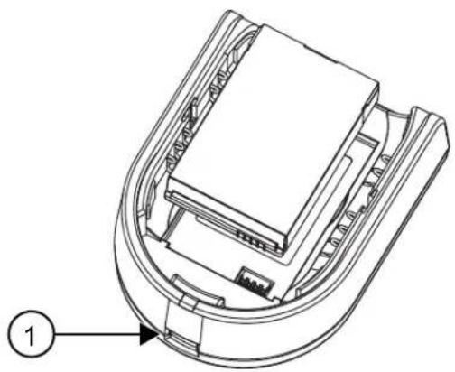
Figure 7: Stand-Alone Battery
| Item Number Description | |
| 1 Micro-USB port |
3.5.1
Charging a Stand-Alone Battery with the Drop-in Tray SUC
Procedure:
1 To charge the battery, insert the connector of the power supply into the micro Universal Serial Bus (USB) port on the front of the drop-in tray charger.
2 Connect the power supply to a proper AC outlet.
3 Insert the battery into the tray, with the inside surface of the battery facing the front of the charger. See Stand-Alone Battery on page 25.
4 Ensure that the slots in the battery are correctly engaged in the charger.
3.5.2
Charging a Stand-Alone Battery with the Drop-in Tray MUC-Optional Accessory
Procedure:
1 Place the charger on a flat surface or mount it on the wall.
2 Insert the power cord plug into the jack on the MUC.
3 Plug the cord into an AC outlet and then into the charger.
4 Insert the battery into the charging pocket with the inside surface of the battery facing the front of the charger.
5 Ensure that the slots in the battery are correctly engaged in the charger.
3.5.3
Estimated Charging Time
The following tables provide the estimated charging time of the battery.
Table 5: Estimated Charging Time
| Charging Solution Standard Li-Ion Battery | |
| Single Unit Charger 5.5 hours | |
| Multi-Unit Charger 4 hours |
3.6
Charging Radio with the Drop-in Tray SUC
Procedure:
1 Place the drop-in Tray Single Unit Charger (SUC) on a flat surface.
2 Insert the connector of the power supply into the Micro USB port on the front of the drop-in tray charger.
3 Connect the correct power supply to a proper AC outlet.
4 Insert the radio with battery installed into the tray, facing down and making sure that the charging contacts on the charger are aligned with the contacts on the radio.
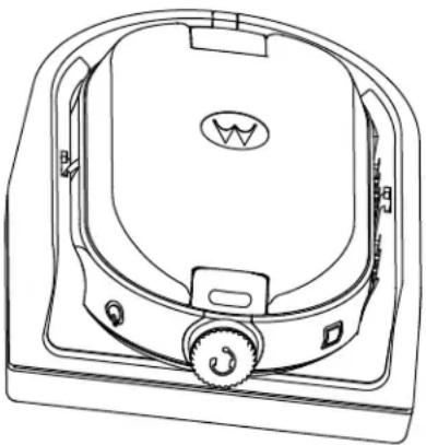
Figure 8: Charging Radio

NOTICE: When charging a battery attached to radio, ensure that the radio is turned off. You can enable or disable the radio to automatically turn off when radio is inserted into the charger feature through Customer Programming Software (CPS).
3.7
Charging with the Drop-In Tray MUC-Optional Accessory
The Multi-Unit Charger (MUC) allows drop-in charging of up to six radios. Each of the six charging pockets can hold a radio with a battery installed. The MUC provides pockets for headset storage.
Procedure:
1 Place the charger on a flat surface or mount it on the wall.
2 Insert the power cord plug into the jack on the MUC.
3 Plug the cord into an AC outlet and then into the charger.
4 Turn off the radio.

NOTICE: When charging a battery attached to radio, ensure that the radio is turned off. You can enable or disable the radio to automatically turn off when radio is inserted into the charger feature through Customer Programming Software (CPS).
5 Insert the radio facing down with battery installed into the charging pocket, ensuring that the radio contacts are aligned with the MUC contacts.

NOTICE: The battery can be charged by using the slot on the flat surface of the charging pocket.
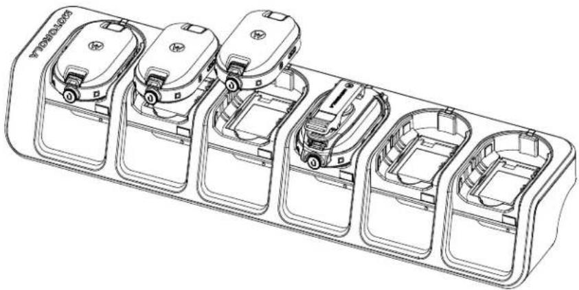
Figure 9: Charging Radios
3.8
Charger LED Indications
On the drop-in charger, the radio charging pocket has an LED Charger.
On the Multi-Unit Charger (MUC), each of the six charging pockets has an LED.

NOTICE: You can clone up to two source radios and two target radios using MUC. For more information on cloning, see Radio Cloning on page 33
For part number details, see Accessories on page 47.
Table 6: Charger LED Indicator
| Status LED Indication | ||
| Battery is charging Steady Red | ● | |
| Battery is fully charged Steady Green | ● | |
| Battery Fault6 | Blinking Red | |
3.9
Checking Battery Status
Procedure:
Short press and release the Power and Battery button.
The Smart Status Glow Ring and Voice Assisted Operation features show the radio battery status.
Table 7: Battery Status
| Battery Level LED Indication | Color | |
| High (50-100%) Green | ||
| Medium (20-50%) Yellow | ||
| Low (3-20%) Red | ||
| Critical (0-3%) Blinking Red |
The radio returns to the current channel color after indicating the battery status.
Chapter 4
Radio Programming through CPS
You can program or change features on your radios by using the Customer Programming Software (CPS) and the CPS Programming Cable.
CPS is available for free as web based downloadable software at http://www.motorolasolutions.com/CLPe.
4.1
Programming the Radio
Prerequisites:
Install the Computer Programming Software (CPS) on your computer.
Ensure that the radio is turned on.
Procedure:
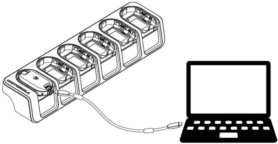
1 Connect the radio by using the Drop-in Charger Tray or the Charging Pocket with PROG label on the Multi-Unit Charger and CPS Programming Cable7.
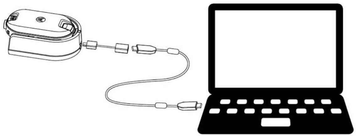
Figure 10: Programming the Radio through a Single Unit Charger

Figure 11: Programming the Radio through a Multi-Unit Charger
2 Set the cable switch to analog.
3 After the radio is connected, open the CPS and select Read on the toolbar to get the radio profile.
You can change the general, audio, menu, channels, scan list, customized PL/DPL settings and select frequencies and PL/DPL codes on each channel.
4 To save the settings, select Write to radio on the toolbar.

NOTICE: For more information on the CPS, see Help menu in the CPS.
4.2
Factory Default Settings
Your radio is programmed at the factory to the following settings.
Table 8: CLP446e Defaults
| Channel Number Frequency Settings (MHz) | Code Value (Hz) Bandwidth (kHz) |
| 1 446.00625 67.0 12.5 | |
| 2 446.01875 | |
| 3 446.03125 | |
| 4 445.04375 | |
| 5 446.05625 | |
| 6 446.06875 | |
| 7 446.08125 | |
| 8 446.09375 |
Table 9: CLP446e Additional 8 Channels/Frequencies through CPS
| Channel Number Frequency Settings (MHz) | Code Value (Hz) Bandwidth (kHz) |
| 9 446.00625 DPL754 125 | |
| 10 446.01875 | |
| 11 446.03125 | |
| 12 445.04375 | |
| 13 446.05625 | |
| 14 446.06875 | |
| 15 446.08125 | |
| 16 446.09375 |

NOTICE: Restricted to 8 channels in Russia by law. Refer to User Guide. Only 446.0-446.1 MHz analog frequencies are available by default. 446.1-446.2 MHz analog frequencies should only be used in countries where these frequencies are allowed by government authorities.
Table 10: CLPe PLUS
| Channel Number Frequencies (MHz) | Code Value (Hz) Bandwidth (kHz) |
| 1 464.55 67.0 12.5 | |
| 2 467.925 | |
| 3 467.85 | |
| 4 467.875 | |
| 5 461.0625 | |
| 6 461.1125 | |
| 7 461.1625 | |
| 8 461.2125 |
Table 11: CLPe PLUS Additional 8 Channels/Frequencies
| Channel Number Frequency Settings (MHz) | Code Value (Hz) Bandwidth (kHz) |
| 9 461.2625 67.0 12.5 | |
| 10 461.3125 | |
| 11 461.3625 | |
| 12 462.7875 | |
| 13 462.8375 | |
| 14 462.8875 | |
| 15 464.4875 | |
| 16 464.5375 |
Chapter 5
Radio Cloning
This feature allows you to clone radio settings from one radio to another.
5.1
Cloning Radio Settings
You can copy the radio settings from the source to another radio.
You can use one of the following unit chargers and cables for cloning:
- CLP Series Single Unit Charger (SUC) kit part number IXPN4028_ ^8 and CLP Series Cloning Cable kit part number HKKN4028_(optional accessory).
- Multi-Unit Charger (MUC) Kit Part Number IXPN4029_(optional accessory)
The MUC does not have to be plugged in for cloning, but both radios require charged batteries.
5.2
Cloning Radios using the Cloning Cable
Prerequisites:
- A fully charged battery on each radio.
- Two Single-Unit Charger (SUC) Kits.
- Both radios are turned off.
- Source radio: Radio to be cloned.
- Target radio: Radio to which the configuration of the source radio is to be copied.
A radio which is programmed with the expanded frequencies (446.00625 MHz-446.19375 MHz) does not support cloning to legacy eight frequency radios.
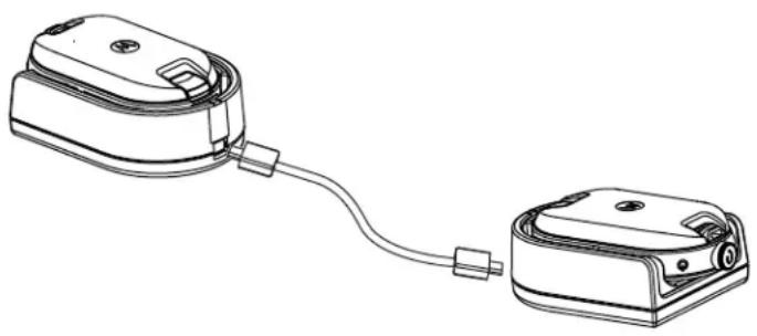
Figure 12: Cloning the Radio through a Single Unit Charger
Procedure:
1 Unplug any cables such as power supply or micro USB cables from the SUC.
2 Plug one side of the cloning cable micro USB to one SUC and plug the other end to the second SUC.

NOTICE:
Ensure the switch on the cloning cable is set to Legacy.
During the cloning process, no power is applied to the SUC. The batteries cannot be charged. A data communication is established between the two radios.
3 Turn on the target radio and place it into one of the SUC.
4 To power the source radio, press and hold the PTT button and the - button simultaneously while turning on the radio until you hear the cloning tone.
5 To start the cloning process, place the source radio in its SUC with an audio accessory, then press and release the Menu button.
If successful, the source radio sounds a good key chirp tone.
If unsuccessful, the source radio sounds bonk tone.
The tone sounds for no more than five seconds.
6 Turn the radios off and on to bring the radios to the user mode by exiting the clone mode when the cloning process is completed.

NOTICE: When the radio is in clone mode, the Auto Power Off feature is not applicable.
5.3
Cloning Radios using the Multi-Unit Charger
Prerequisites:
- A fully charged battery on each radio.
- CLP Series Multi-Unit Charger (MUC).
- Both radios are turned off.
- Source radio: Radio to be cloned.
- Target radio: Radio to which the configuration of the source radio is to be copied.
Procedure:
1 To put the source radio into clone mode, press and hold the source radio PTT button and the -button simultaneously while turning on the radio until you hear the cloning tone.
2 Place the source radio into one of the charging pockets that has the CLONE label.
3 Turn on the target radio and place it in the pairing charging pocket that has the CLONE label and start the cloning process.
4 To start the cloning process, press the Menu button on the source radio.
The source radio generates the start clone tone.
5 To activate the radio, turn off and on the radios when cloning process is completed.
6 To clone another radio, repeat step 3 to step 5.
7 To exit clone mode on the source radio, turn off the radio.
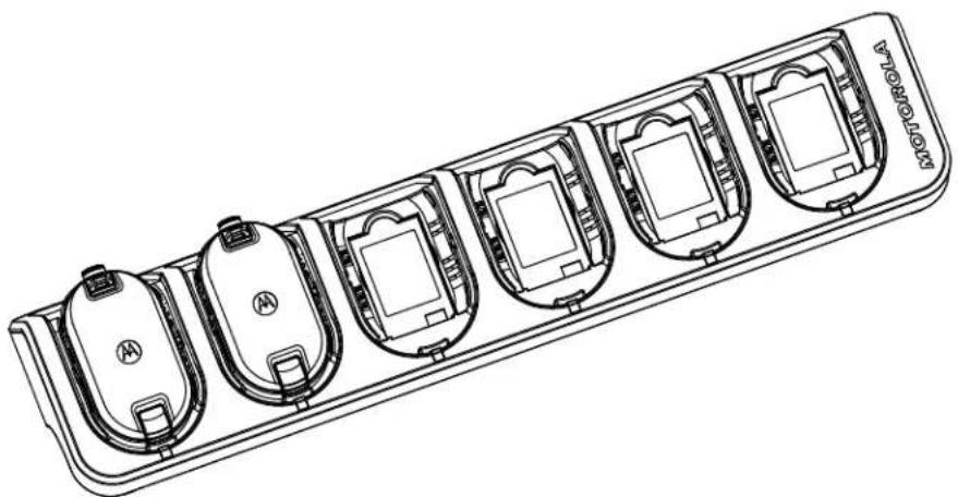
Figure 13: Cloning the Radio through a Multi-Unit Charger
5.4
Troubleshooting Cloning Mode
When and where to use:
The radio audible voice announces "Bonk" indicating that the cloning process has failed. In the event that cloning fails, perform each of the following steps before attempting to start cloning process again.
Procedure:
1 Ensure that the batteries on both radios are fully charged and engaged properly on the radio.
2 Check the cloning cable connection on both Single-Unit Chargers (SUC).
3 Ensure that there is no debris in the charging tray or on the radio contacts and the radio contact is touching the SUC or MUC contact firmly.
4 Ensure that the Target Radio is turned on.
5 Ensure that the Source Radio is in cloning mode.
6 Ensure that the two radios are both from the same frequency band, same region and have the same transmission power.

NOTICE: This cloning cable is designed to operate only with compatible Motorola Solutions SUC.
When ordering cloning cable kit, refer to part number HKKN4028_. For more information about the accessories, see Accessories on page 47.
Chapter 6
Advanced Radio Configuration
Advanced Radio Configuration allows you to configure settings from a pre-programmed list without using a computer.
Advanced Configuration Mode allows you to customize the following settings:
Channels
- Frequencies
- Codes (CTCC/DPL)
Frequencies allow you to select frequencies for each channel. Codes help minimize interference by providing you with a choice of code combinations that filter out static, noise, and unwanted messages.
6.1
Entering Advanced Radio Configuration Mode
Prerequisites:
Turn the radio off.
Procedure:
1 Press the PTT, + button and Power button simultaneously and hold for 3 to 5 seconds until you hear a sound and the voice prompt Programming Mode.
The LED blinks green.
2 To select the settings you want to change, press the Menu button.
The followings are the settings that you can change:
- Channel (for multi-channel models)
Frequency
Code
The voice announcements indicate the menu items and their current settings.
3 To change the settings, press the + or - button.
4 To go to the next menu item, press the Menu button.
5 To exit the Advanced Radio Configuration mode, press and hold the PTT button until you hear a sound.
Chapter 7
Troubleshooting
The following table explains the ways to troubleshoot if the symptom occurred.
7.1
Symptom and Solutions
Procedure:
1
| If... Then... | |
| No power Recharge or replace the Li-Ion battery. | NOTICE: Extreme operating temperatures may affect battery life. See Battery Specifications on page 23. |
| Hearing other noises or conversation on a channel | Frequency or Interference Eliminator Code may be in use. Perform one of the following actions: ·Confirm Interference Eliminator Code is set. ·Change frequencies or codes settings on all radios. ·Ensure the radio is at the right frequency and code when transmitting. |
| Message Scrambled Scramble Code might be on or the setting does not match other radio settings. Change the settings through Customer Programming Software (CPS). | |
| Audio quality not good enough Radio settings might not be match correctly. Check the frequencies, codes, and bandwidths to ensure the settings are the same in all radios. | |
| Limited talk range Perform one of the following actions: ·Check for clear line of sight to improve transmission. Avoid being near steel, concrete structures, heavy foliage, buildings, or vehicles. ·Change the placement of the radio. ·To increase range and coverage, you can reduce obstructions or increase power. UHF radios provides greater coverage in industrial and commercial build- | |
| ings. Increasing power provides greater signal range and increased penetration through obstructions. | |
| Message not transmitted or received Perform | one of the following actions: • Ensure the PTT button is completely pressed when transmitting. • Confirm that the radios have the same Channel, Frequency, Interference Eliminator Code, and Scramble Code settings. See Transmitting and Receiving on page 16. • Recharge, replace, or reposition batteries. See Battery Specifications on page 23. • Change the radio placement. Obstructions and operating indoors, or in vehicles, may interfere. • Verify that the radio is not in Scan mode. See Scanning Radio Channels on page 21. |
| Heavy static or interference Radios are too close. Ensure the transmitting and receiving radios are at least 5 ft (1.5 m) apart. Radios are too far apart or obstacles are interfering with transmission. | |
| Low batteries Recharge or replace Li-Ion battery. | NOTICE: Extreme operating temperatures affect battery life. See Battery Specifications on page 23. |
| Drop-in Charger LED light does not blink Perform | one of the following actions: • Verify that the radio and battery is properly inserted. • Check the battery and charger contacts to ensure that they are clean and charging pin is inserted correctly. See Charging a Stand-Alone Battery with the Drop-in Tray SUC on page 25 and Charger LED Indications on page 27. |
| Battery does not charge although it has been placed in the drop-in charger for a while | Perform one of the following actions: • Verify the drop-in tray charger is properly connected and corresponds to a compatible power supply. See Charging a Stand-Alone Battery with the Drop-in Tray SUC on page 25. |
If... Then...
- Check the charger LEDs indicators to see if the battery has a problem. See Charger LED Indications on page 27.
Chapter 8
Use and Care
This chapter explains the maintenance of the radio.
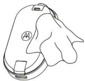
Use a soft damp cloth to clean the exterior

Do not immerse in water
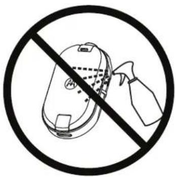
Do not use alcohol or cleaning solutions
If the radio is submerged in water:
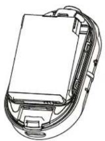
Turn the radio off and remove batteries
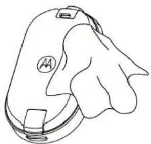
Dry with soft cloth
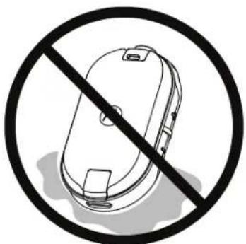
Do not use the radio until it is completely dry

NOTICE: Radio is IP54 only when the dust cover or audio accessory is plugged into the connector.
Chapter 9
Radio Frequency and Code Chart
The following tables show the frequency information and are useful when using Motorola Solutions CLPe Series Two-Way Radios with other business radios.
9.1
CLP446e Frequency List
Table 12: CLP446e Model Defaults
| Freq # Frequency Settings (MHz) Bandwidth (kHz) |
| 1 446.00625 12.5 |
| 2 446.01875 12.5 |
| 3 446.03125 12.5 |
| 4 445.04375 12.5 |
| 5 446.05625 12.5 |
| 6 446.06875 12.5 |
| 7 446.08125 12.5 |
| 8 446.09375 12.5 |
Table 13: CLP446e Additional 8 Frequencies through CPS
| Freq # Frequency Settings (kHz) Bandwidth (kHz) |
| 9 446.10625 12.5 |
| 10 446.11875 12.5 |
| 11 446.13125 12.5 |
| 12 446.14375 12.5 |
| 13 446.15625 12.5 |
| 14 446.16875 12.5 |
| 15 446.18125 12.5 |
| 16 446.19375 12.5 |
| NOTICE: Restricted to 8 channels in Russia by law. Only 446.0–446.1 MHz analog frequencies are available by default. 446.1–446.2 MHz analog frequencies should only be used in countries where these frequencies are allowed by government authorities. |
9.2
CLPe PLUS Frequencies
Table 14: CLPe Plus UHF Frequencies
Frequencies can be edited from the frequency table via the CPS.
| Freq# Freq (MHz) Band Width(kHz) | Freq# Freq (MHz) Band Width(kHz) |
| 1 464.5000 12.5 46 466.3375 12.5 | |
| 2 464.5500 12.5 47 466.3625 12.5 | |
| 3 467.7625 12.5 48 467.7875 12.5 | |
| 4 467.8125 12.5 49 467.8375 12.5 | |
| 5 467.8500 12.5 50 467.8625 12.5 | |
| 6 467.8750 12.5 51 467.8875 12.5 | |
| 7 467.9000 12.5 52 467.9125 12.5 | |
| 8 467.9250 12.5 53 469.4875 12.5 | |
| 9 461.0375 12.5 54 469.5125 12.5 | |
| 10 461.0625 12.5 55 469.5375 12.5 | |
| 11 461.0875 12.5 56 469.5625 12.5 | |
| 12 461.1125 12.5 57 462.1875 12.5 | |
| 13 461.1375 12.5 58 462.4625 12.5 | |
| 14 461.1625 12.5 59 462.4875 12.5 | |
| 15 461.1875 12.5 60 462.5125 12.5 | |
| 16 461.2125 12.5 61 467.1875 12.5 | |
| 17 461.2375 12.5 62 467.4625 12.5 | |
| 18 461.2625 12.5 63 467.4875 12.5 | |
| 19 461.2875 12.5 64 467.5125 12.5 | |
| 20 461.3125 12.5 65 451.1875 12.5 | |
| 21 461.3375 12.5 66 451.2375 12.5 | |
| 22 461.3625 12.5 67 451.2875 12.5 | |
| 23 462.7625 12.5 68 451.3375 12.5 | |
| 24 462.7875 12.5 69 451.4375 12.5 | |
| 25 462.8125 12.5 70 451.5375 12.5 | |
| 26 462.8375 12.5 71 451.6375 12.5 | |
| 27 462.8625 12.5 72 452.3125 12.5 | |
| 28 462.8875 12.5 73 452.5375 12.5 | |
| 29 462.9125 12.5 74 452.4125 12.5 | |
| 30 464.4875 12.5 75 452.5125 12.5 | |
| 31 464.5125 12.5 76 452.7625 12.5 | |
| 32 464.5375 12.5 77 452.8625 12.5 | |
| 33 464.5625 12.5 78 456.1875 12.5 | |
| 34 466.0375 12.5 79 456.2375 12.5 | |
| 35 466.0625 12.5 80 456.2875 12.5 | |
| 36 466.0875 12.5 81 468.2125 12.5 | |
| 37 466.1125 12.5 82 468.2625 12.5 | |
| 38 466.1375 12.5 83 468.3125 12.5 | |
| 39 466.1625 12.5 84 468.3625 12.5 | |
| 40 466.1875 12.5 85 468.4125 12.5 | |
| 41 466.2125 12.5 86 468.4625 12.5 | |
| 42 466.2375 12.5 87 468.5125 12.5 | |
| 43 466.2625 12.5 88 468.5625 12.5 | |
| 44 466.2875 12.5 89 468.6125 12.5 | |
| 45 466.3125 12.5 90 468.6625 12.5 |
9.3
CTCSS/DPL Interference Eliminator Codes
Table 15: CTCSS/DPL Interference Eliminator Codes
| CTCSS Code CTCSS/DPL | Code DPL Code DPL Code DPL Code | ||||||||
| 0 Disabled 24 | 151.4 | 47 54 71 243 | 95 | 445 | |||||
| 1 67.0 | 25 | 156.7 | 48 65 | 72 244 | 96 | 464 | |||
| 2 71.9 | 26 | 162.2 | 49 71 | 73 245 | 97 | 465 | |||
| 3 74.4 | 27 | 167.9 | 50 72 | 74 251 | 98 | 466 | |||
| 4 77.0 | 28 | 173.8 | 51 73 | 75 261 | 99 | 503 | |||
| 5 79.7 | 29 | 179.9 | 52 74 | 76 263 | 100 | 506 | |||
| 6 | 82.5 | 30 | 186.2 | 53 | 114 | 77 | 265 | 101 | 516 |
| 7 | 85.4 | 31 | 192.8 | 54 | 115 | 78 | 271 | 102 | 532 |
| 8 | 88.5 | 32 | 203.5 | 55 | 116 | 79 | 306 | 103 | 546 |
| 9 | 91.5 | 33 | 210.7 | 56 | 125 | 80 | 311 | 104 | 565 |
| 10 | 94.8 | 34 | 218.1 | 57 | 131 | 81 | 315 | 105 | 606 |
| 11 | 97.4 | 35 | 225.7 | 58 | 132 | 82 | 331 | 106 | 612 |
| 12 | 100.0 | 36 | 233.6 | 59 | 134 | 83 | 343 | 107 | 624 |
| 13 | 103.5 | 37 | 241.8 | 60 | 143 | 84 | 346 | 108 | 627 |
| 14 | 107.2 | 38 | 250.3 | 61 | 152 | 85 | 351 | 109 | 631 |
| 15 | 110.9 | 122 | 69.3 | 62 | 155 | 86 | 364 | 110 | 632 |
| CTCSS Code CTCSS/DPL | Code DPL Code DPL Code DPL Code |
| 16 114.8 39 23.0 63 156 87 365 111 654 | |
| 17 118.8 40 25.0 64 162 88 371 112 662 | |
| 18 123.0 41 26.0 65 165 89 411 113 664 | |
| 19 127.3 42 31.0 66 172 90 412 114 703 | |
| 20 131.8 43 32.0 67 174 91 413 115 712 | |
| 21 136.5 44 43.0 68 205 92 423 116 723 | |
| 22 141.3 45 47.0 69 223 93 431 117 731 | |
| 23 146.2 46 51.0 70 226 94 432 118 732 | |
| 119 734 |
Table 16: CTCSS/DPL Interference Eliminator Codes (Continued)
| DPL Code | DPL Code | DPL Code | DPL Code |
| 120 743 | 146 Inverted DPL | 55 | 171 Inverted DPL 80 195 Inverted DPL |
| 104 | |||
| 121 754 | 147 Inverted DPL | 56 | 172 Inverted DPL 81 196 Inverted DPL |
| 105 | |||
| 123 645 | 148 Inverted DPL | 57 | 173 Inverted DPL 82 197 Inverted DPL |
| 106 | |||
| 124 Cus-tomized | 149 Inverted DPL | 58 | 174 Inverted DPL 83 198 Inverted DPL |
| 107 | |||
| 125 Cus-tomized | 150 Inverted DPL | 59 | 175 Inverted DPL 84 199 Inverted DPL |
| 108 | |||
| 126 Cus-tomized | 151 Inverted DPL | 60 | 176 Inverted DPL 85 200 Inverted DPL |
| 109 | |||
| 127 Cus-tomized | 152 Inverted DPL | 61 | 177 Inverted DPL 86 201 Inverted DPL |
| 110 | |||
| 128 Cus-tomized | 153 Inverted DPL | 62 | 178 Inverted DPL 87 202 Inverted DPL |
| 111 | |||
| 129 Cus-tomized | 154 Inverted DPL | 63 | 179 Inverted DPL 88 203 Inverted DPL |
| 112 | |||
| 130 Inverted | 155 Inverted DPL | 64 | 180 Inverted DPL 89 204 Inverted DPL |
| 113 | |||
| 131 Inverted | 156 Inverted DPL | 65 | 181 Inverted DPL 90 205 Inverted DPL |
| 114 | |||
| 132 Inverted | 157 Inverted DPL | 66 | 181 Inverted DPL 90 206 Inverted DPL |
| 115 | |||
| DPL 41 | |||
| 133 Inverted DPL 42 | 158 Inverted DPL 67 | 182 Inverted DPL 91 207 Inverted DPL 116 | |
| 134 Inverted DPL 43 | 159 Inverted DPL 68 | 183 Inverted DPL 92 208 Inverted DPL 117 | |
| 135 Inverted DPL 44 | 160 Inverted DPL 69 | 184 Inverted DPL 93 209 Inverted DPL 118 | |
| 136 Inverted DPL 45 | 161 Inverted DPL 70 | 185 Inverted DPL 94 210 Inverted DPL 119 | |
| 137 Inverted DPL 46 | 162 Inverted DPL 71 | 186 Inverted DPL 95 211 Inverted DPL 120 | |
| 138 Inverted DPL 47 | 163 Inverted DPL 72 | 187 Inverted DPL 96 212 Inverted DPL 121 | |
| 139 Inverted DPL 48 | 164 Inverted DPL 73 | 188 Inverted DPL 97 213 Inverted DPL 123 | |
| 140 Inverted DPL 49 | 165 Inverted DPL 74 | 189 Inverted DPL 98 214 Customized DPL | |
| 141 Inverted DPL 50 | 166 Inverted DPL 75 | 190 Inverted DPL 99 215 Customized DPL | |
| 142 Inverted DPL 51 | 167 Inverted DPL 76 | 191 Inverted DPL 100 216 Customized DPL | |
| 143 Inverted DPL 52 | 168 Inverted DPL 77 | 192 Inverted DPL 101 217 Customized DPL | |
| 144 Inverted DPL 53 | 169 Inverted DPL 78 | 193 Inverted DPL 102 218 Customized DPL | |
| 145 Inverted DPL 54 | 170 Inverted DPL 79 | 194 Inverted DPL 103 219 Customized DPL |
Chapter 10
Motorola Solutions Limited Warranty
10.1
Warranty Information
The authorised Motorola Solutions dealer or retailer where you purchased your Motorola Solutions two-way radio and/or original accessories will honour a warranty claim and/or provide warranty service. Please return your radio to your dealer or retailer to claim your warranty service. Do not return your radio to Motorola Solutions. To be eligible to receive warranty service, you must present your receipt of purchase or a comparable substitute proof of purchase bearing the date of purchase. The two-way radio should also clearly display the serial number. The warranty will not apply if the type or serial numbers on the product have been altered, deleted, removed or made illegible.
10.2
V. WHAT THIS WARRANTY DOES NOT COVER
1 Defects or damage resulting from use of the Product in other than its normal and customary manner.
2 Defects or damage from misuse, accident, water, or neglect.
3 Defects or damage from improper testing, operation, maintenance, installation, alteration, modification, or adjustment.
4 Breakage or damage to antennas unless caused directly by defects in material workmanship.
5 A Product subjected to unauthorized Product modifications, disassemblies or repairs (including, without limitation, the addition to the Product of non-Motorola Solutions supplied equipment) which adversely affect performance of the Product or interfere with Motorola Solutions normal warranty inspection and testing of the Product to verify any warranty claim.
6 Product which has had the serial number removed or made illegible.
7 Rechargeable batteries if:
- any of the seals on the battery enclosure of cells are broken or show evidence of tampering.
- the damage or defect is caused by charging or using the battery in equipment or service other than the Product for which it is specified.
8 Freight costs to the repair depot.
9 A Product which, due to illegal or unauthorized alteration of the software/firmware in the Product, does not function in accordance with Motorola Solutions published specifications or the FCC certification labeling in effect for the Product at the time the Product was initially distributed from Motorola Solutions.
10 Scratches or other cosmetic damage to Product surfaces that does not affect the operation of the Product.
11 Normal and customary wear and tear.
Chapter 11
Accessories
Table 17: Audio Accessories
| Part No. Description | |
| PMLN8077_Over-the-ear earpiece, Single Pin | |
| PMLN8125_Over-the-ear earpiece, Single Pin, Short Cord | |
| PMLN8190_Surveillance earpiece, Single Pin |
Table 18: Batteries
| Part No. Description | |
| HKNN4013_CLP Series High Capacity Li-Ion Battery | |
| PMLN8066_CLPe High Capacity Li-Ion Battery Door |
Table 19: Carry Accessories
| Part No. Description | |
| PMLN8064_CLPe Series Magnetic Case | |
| PMLN8065_CLP Series Swivel Belt Clip Holster |
Table 20:Chargers
| Part No. Description | |
| IXPN4029_CLP Series Multi-Unit Charger (MUC) | Kit |
| IXPN4028_9 | CLP Series Single-Unit Charger (SUC) Kit |
Table 21: Programming Cables
| Part No. Description | |
| HKKN4027_CLP Series CPS Cable | |
| HKKN4028_CLP Series Cloning Cable |
CLP446e/CLPe PLUS Brugervejledning
Indhold
Copyright på dokumentation. 4
Ansvarsfraskrivelse 5
Ophavsret pa computersoftware 6
3 Slip knappen PTT for at lytte.
Radioprogramming via CPS
·PRICAUCION: Los car
learning.motorolasolutions.com.
Abra 7: Onallo akkumulator

www.motorolasolutions.com/CLPe.
4.1
Portofoonprogramming via CPS
Aktiveres via CPS (Customer Programming Software).
Radioprogramming via CPS
Du kan programme mere aller endre funksjoner pa radioen ved hjelp av CPS (Customer Programming Software) og CPS-programmeringskabelen.
CPS-programvaren kan lastinges ned gratis fra http://www.motorolasolutions.com/CLPe.
Relaterte koblinger
Programmere radioen paside 34
Fabrikkinstillinger pà side 35
4.1
Programmere radioen
Forkrav:
Installer CPS (Computer Programming Software) på datamaskinen.
Kontroller at radioen er slatt pa.
Prosedyre:
1 Koble til radioen ved Å bruke laderen med holder eller ladefordypningen merket PROG pa laderen for flere enheter og CPS-programmeringskabelen

Figur 10: Programmere radioen via en lader for en entet
Figur 11: Programmere radioen via en lader for flere enheter
2 Sett kabelbryteren til analog.
3 Nár radioen er tilkoblet, apner du CPS og velger Les pa verktøylinjen for a hente radioprofilen. Du kan endre generelle innstlinger, innstlinger for lyd, meny, kanaler, skanneliste og tilpassede PL/DPL-innstlinger og velge frekvenser og PL/DPL-koder for hvr kanal.
4 Nár du vil lagre innstillingene, velger du Skriv til abonnent pa verktøylinjen.

Radioprogramming via CPS pa side 34
4.2
Fabrikinnstillinger
Tabell 8: Standardinnstlinger for CLP446e
| Kanalnummer Frekvensinnstillinge r (MHz) | Kodeverdi (Hz) Bändbrede (kHz) |
| 1 446,00625 67,0 12,5 | |
| 2 446,01875 | |
| 3 446,03125 | |
| 4 445,04375 | |
| 5 446,05625 | |
| 6 446,06875 | |
| 7 446,08125 | |
| 8 446,09375 |
Tabell 9: Ytterligere 8 kanaler/frekvenser via CPS for CLP446e
| Kanalnummer Frekvensinnstillinge r (MHz) | Kodeverdi (Hz) Bändbrede (kHz) |
| 9 446,00625 DPL754 12,5 | |
| 10 446,01875 | |
| 11 446,03125 | |
| 12 445,04375 | |
| 13 446,05625 | |
| 14 446,06875 | |
| 15 446,08125 | |
| 16 446,09375 |

Radioprogramming via CPS pá side 34
Kapittel 5
Radiokloning
www.motorolasolutions.com/CLPe.
4.1
Kanaly
danymi
Kody (CTCC/DPL)
V. CZEGO NIE OBEJMUJE GWARANCJA
Tabela 18: Akumulatory
OTka3 OT OTBeTCTBeHHOCTH 5
Abtopckne npaba Ha komnbIOpTepHoe nporpaMMhoe o6ecneueHne. 6
HfopMaun no Texnke 6e3onacHocTn np na6oTe c akymyIaTopamn, 3apAdbmU yCTpoiCtBaMn n ayDnoakceccyapamn.7
Yka3aHnno6e3oNaChOHKcNlyatau.. 7
Akyctnuecka 6e3oNaChocTb. 8
CtanhaptbI 6e30nacHOCTN B OTHOWeH N BO3dEICTBnpaDIOuAcTOTHOrO n3JyueHn. 9
YbeomJIeHne Ira nIb3OBeTeJei 10
BvBeHne 11
KoMnIeKtaUyapokBkn. 11
Tlaba 1. O63op paAnocTaHcun.. 13
Tnaba 2. Hauano pa6oTbI 14
2.1 YctaHOBka aKkymyIaTopa 14
2.2Подклоченп探测дьхaydnoakceccyaopoB.. 15
2.3BkIIOHeH/ByIKIOHeHpepaIOcTaHcH.. 17
2.4 Perynipobka rpoMkoCTn 17
2.5 YcTaHOBka n CHrTne cyTnPa c NOBOpOTbIM NOrChbIM 3aXIMOM... 17
2.6 Peredaya npneem 19
YcTaHOBka akkymyIaTopa Ha cTp. 14
IopKnIOueHne npoBOdNbIx ayDnOaKceccyapOB Ha cTp. 15
BkIIOueHHe/ByIKJIIOueHHe paADIOCTaHcIM Ha cTp. 17
PerynpoBkra rpoMkoctNa cTp.17
YcTaHObKa n ChrTne cyTnPa c NOBOPOTbIM NORChbIM 3aXIMOM Ha cTp.17
Ipepaa n npneHa cTp. 19
HacpoK MeHO Ha cTp. 19
Bb6op KaHana Ha cTp. 20
MOHITOPNI KAHAJIOB Ha cTp.24
CkaHIpOBaHne Ha cTp. 24
DInHaMnueckoe cKaHIpOBaHHe npraMo CBA3n Ha cTp. 25
OTnpabKa ToHaIbHbIX CnHraIOB Bbl3Oba Ha cTp.25
OTKJIUOHeHHe 3Byka paAnocTaHcHn Ha cTp.26
3ckaIaIauIy BblIOBa Ha cTp. 26
2.1
YcTaHOBka aKKyMylrTopa
PpoceDypa
1 B HnKHe N acTn KpbIuN O TceKa aKKMyJrTopa NODHIMTe 3aueJIky N CHIMNTe KpbIuKy OTceKa aKKMyJrTopa paDIOCTAHcUN.
2 BbipOBHnTe KOHTaKtBt aKKyMnyTota OTHoCHTeNbHO KOHTaKToB B OTCKe aKKyMnyTota.
3 IpeKdJe Yem HauKaTb N 3aФuKcnpoBaTb, BCTaBbTe aKKyMylrTop B OTceK aKKyMylrTopa KOHTaKTAMn BnepeI.
4 YctaHOBNTe KpbIbIKy OTCeKa aKKMyJrTopa Ha paAnocTaHcHIO Hn HaxMnte Ha 3aueKky, YTo6bl 3akpItb KpbIbIKy OTCeKa aKKMyJrTopa.
PncyHok 2: YcTaHObKa aKKymyIaTopa
BepHyTbcK npoueccy
Hauano pa60tbHa cTp.14
2.2
BbIKIOUHTe nITaHHe paIIOCTaHIN.
PpoceDypa
1 PoiKJIIOUHTe ayDIOAOKCECCyap K paIIOCTaHcIM TaKIM Obpa3OM, UTo6bl 3HaYok pa36JIOKIpOBKn Ha ayDIOAOKCECCyape 6bln ObaPaeH K pepeJeH CTOpOHe paIIOCTaHcIM.
Y6eIntecb, YTO INHnKaTOp Ha ayDnOaKceccyape n paDnOCTaHcN COBMeIeHbl.
2BkpUHBaIe uTekep ayDnOaKceccyapa B pa3bEm, noka 3HaOH K 6IoKnOpBKN He 6yDet o6paueH K nepeDHe CTopoHe paAnocTaHcN IN HdNKaTOpbl He 6ydyT COBMeuHbI.

PncyHok 3: PnoknloueHne npoBOnbix ayDnOaKceccayapOB
3 BkIIOHTe paIDIOCTaHcHIO.
4 HaKMTe KHOkny CoctOaryne akKymyIaTopa, MeHIO NnYnpaBJIeHne rPOMKOcTBIO, YTO6bI npOBepntb HAIuNue 3BykaYepe3ayDnOyCToICTBO.
Tabnua 1: HactpoKa BepxHero INdKaTopa, ecnn npobodno aydoakceccyap He IIOKJIIOUeH NNI OTKJIIOUeH
BkIIOUeHne/ByIKJIIOUeHne paIIOCTaHcN
PpoeDypa
1 TTo6bI BKNIOUHTb paIIOCTaHcIIO, HAnMITE u yIepKINBaITe KHOKNy NITaHnN aKKMyJrTopa, noka He ycblWite KOpOTKn ToHaJIbHbI CnHaN I He 3arOpNTc INTeJIeKTyalbHbI INHdNKATOP COCTOHN.
2 To6bI BbIKNIOHTb paIIOCTaHcIIO, HAKMITE u ydePKNBaTe KHOKNy nITaHnA aKKymJrTopa, NOKa He ycbluNTe KOpOTKm TOHaJIbHbI CNrHaI, a KpaCHbI KOJIbCeBOI INTEJIeKTyAlbHbI INHdNKATOp COCTOHNrHE MIRHT ODNH pa3.
BepHyTbcK npoueccy
Hauano pa60tbHa cTp. 14
2.4
PergunpoBka rpoMkoCTn
PpoaeDypa
1UTo6bIyBEnHnHTb rPOMKoCTb, HAXMnTe KHOJky (+)

YBEIDOMJIENHE:
PaioocTaHnIa IMeet 15 ypoBHe rpoMkoCTn.
2Yto6bIyMeHbWHTB rPOMKoCTb,HaXMnTe KhoNky(-).
BepHyTbcK npoueccy
Hauano pa6oTbHa cTp. 14
2.5
YcTaHOBka n ChrTne cyTnpa c NOBOPOTbIM NORCHbIM 3aXHMOM
PádiocTahuŋn ppeIaHOT pa3JIuHbIe BapnaHTbI akceccyapOB dIЯ nepeHoCKN. Cnncok akceccyapOB, oO6peHHbIX KOMpaHnei Motorola Solutions, cm. B pa3dene http:// www.motorolasolutions.com/CLPe.
PpoceDypa
1T06bBCTaBnTBpaNocTahuHOBpyTJp,BbINOHHTeCneDyUOuneJeICTBna:
a3aBnHbTe HnXHHIOU qAcTb paAnocTaHcUN B cyTJnp.
b HaedeHbTe BepxHIO UacTb cyTpaHa paAnocTaHcIO B MeCe pa3bema dIa akceccyapOB.
MN006181A01-AB
CBeToDnOuHbI INHdNkaTOp yKa3bBaet ZbET HOBOrO KaHana.
3 HaxmTe KhoNkpy PTT nOoTBePKeHn nn KaHaI 6yJeT aKTHBnPoBaH uepe3 TpN CeKyHdbI.
BepHyTbcK npoeccy
Hauano pa60tbHa cTp. 14
CcbiKn no TeMe
HacpoK KaHaJa No yMOnUaHHIO dJa CPS Ha cTp. 21
CBeToIOIOHbIe INHdIKaTOpbI Ha cTp.23
2.8.1
Hac tropon Kaha na no ymoJIaHHIO dIg CPS
B tabnue onncanbI hactpoyn KaHajno ymoJuaHIO nIPO CPS nI nporpaMnpobAHn paNocTaHn.
Ta6nua 3: HacpoK KaHana dna CPS
Bb6op kaHana Ha cTp. 20
2.8.2
CBeToIIOHbIe NHdNkAToPbI
| Функция CBetODиODнь ИndиКаТор | |
| В ресиме мониторигra Горот одни | цBetOM Ha KaHaI. |
| ToHaJIbHbI сИгнaI BvI3OBA OndHokpAte | HO MiraeT OndHIM ZBETOM Ha KaHaI. |
| Ссановане Круrogая ИndиКацяп | TOчавов STpeПke, CBetODиODы ПО череди загорaitс по оДному. Посlete заBERшени КадOTO zIKNla CBet ИndиКаци ИЗмehЯетсу CBepxHero CBetODиОda. |
| Вклюveни и OTКлюveни Берхни кр расьи и OCTabшійся белій ИndиКатportы 3aГorapAJTcRуКорOTKoe BpEma. | |
| Расшиpenная koHфиграця radnooctanuhi | Miraet 3eJIeHbIM. |
| Образнaya CBЯзь с aydnopa3bemom | ИндиКaTOp MiraeT сIHIM, ecIIпри ВКЛчЕни пITAнь НET akCEccyapa. СbetODиODнь ИndиКaTOp 6bICTpo MiraeТ кpacHBIM ФиJOleTOBbIM nonepemeHNo, KOrda akCEccyap OKIQUeH. |
BepHyTbcK npoueccy
Bb6op kaHana Ha cTp. 20
CcbiKn no TeMe
INHdNkATOp rPOMKoCTn Ha cTp.24
MN006181A01-AB
Глaba 2: Hayano pa60tbi
2.8.2.1
CBeToIIOHbIe HnDnKaTOpbl Ha cTp.23
2.9
MOnHTOpINr KaHaJIOB
Ppoueypa
1 YtO6bI BKNIOHTb peKIM Bbl6opa MOHITOpINrA, HAXMNTe KHOKNy MeHIO n nepeiDnTe K nyHKTy Bbl6op MOHITOpINrA.
EcnM MoHToPnHr OTKJIIOUeH, Bbl yCJIbIuNTe roIOcoBOe COO6UeHne 06 aKTHBaUN pexmAM MOHTOpHHra HaxKaTHe M KHOKN + HNI -.
2 4To6bI OTKJIIOHTb peKIM MOHITOpHra, HAKMITE KHOKNy +JIN -.
Korda pekIM MOHITOpHra BKNIOueH, Bbl CJIbIuNTe CTaTNueckn 3ByK, ecn aKTINBHOCTb KaHaNaOTCYTCTByET, INN 3ByK, ecn KaHaJAKTINBEH.
3 UTo6bI BKNIOUHTb peKIM MOHITOPINrA, BKNIOUHTe MOHITOPINrYepe3 MeHIO N DoXJNTecb OKOHuaHn TaMayTa MeHIO.
4 IJIy BbIXOa n3 peKIMa MOHITOpHra OTNcyTnTe KHOIky PTT.
BepHytbcK npoeccy
Hauano pa6oTbHa cTp. 14
2.10
Сkaн上诉布。
Ha moencl CP446e n CLPe PLUS moXHo cKaHIpOBaTb do 16 kaHaJIOB.
Korda paNocTaHnra ObHApXkBaet aKTHBHOCTb, cKaHnpOBaHne npEkpaaeTcR n paNOCtHnra 6IokpyETcHa aKTHBHom KaHane. 3To daet Bam BO3MOxHOCTb CbluTa b pa3roBaPbTa b C nepeDaIOUIM NOJb3ObaTeIeM, He nepeKlIOyA KaHJI.
BepHyTbcK npoeccy
Hauano pa60tbHa cTp. 14
CcbiHKn no Teme
CkaHnpoBaHnne paAnokHaNoB Ha cTp. 25
2.10.1
СkaHnObaHnne paIOnKaHaJIOB
PpoceDypa
1Дляпесдакункту"РекIMСанровая"нakMITEКONky MeHIO.
EcnckaHnpoBaHne OTKJIIOUeHO, Bbl yCJIbIuNTe rOIOcoBOe COOOHne 6 akTNaCmCKaHnpoBaHna HaxkTaHm KHOJKN + NIN -
2 706bI aKTHBnPoBaTb cKaHnPoBaHne, HaxMnte KHOKNy + nIn -
Ecnn cKaHnpoBaHne BKNIOyeHO, Bbl yCnblIInTe rONOCBOe COO6ueHne 06 DeaKTNbauu nCKaHnpoBaHna HaxaTHeM KHOKn + Nnn -.
3 Yto6bI DeakTNBnpoBaTb cKaHnpoBaHHe, HAKMITE KHOKNy + nJIn -
BepHyTbcK npoeccy
CkaHIpOBaHHe Ha cTp.24
2.11
DINHAMUeCKoe cKaHnPOBaHne npaMOcBra3N
3aDeiCTBOBaHHoro B CnCTeMax DByCTOpOHHe paNOCB3N.
HnHaMnueckoe cKaHnObaHne npraMoCb3n aKTHBnpyETcHa KaHaJe peTpHaHCnTOpa C nOMoUbIO IPO CPS dI nporpaMMnpoBaHna paDIOCTaHcun. 3Ta yHKun no3BOJareT paDIOCTaHcun cKaHnPoBaTb YAcTObI nepeDaUn n npiema KaHaJa peTpHaCnTOpa.

YBEIDOMJIENHE:
3TaФyHKUHIMeET6OJIeBbICOKNIIpIOpHT,YeMpeKIMcKaHIpOBaHn. EcIn DNHaMHueCKOE cKaHIpOBaHne IprAMoCBsI IN cKaHIpOBaHne BKNIOyeHbI Ha DOMaSHHeM KaHaJe,paNIOCTAHmIOMeKTe NODepKINBaT TOJbKO dNHAmHueCKoe cKaHIpOBaHne nprMoC b83n. 3TaФyHKUHDOCTyHnToJbKO B MOnEn CLPe PLUS.
BepHyTbcK npoueccy
Hauano pa60tbl Ha cTp. 14
2.12
OTnpaBka ToHaJIbHbIX CNrHaJIOB Bbl3OBA
PpoceDypa
1 InepexoKa NyHKTy ToHaJIbHbI CNrHaJI BbI3OBA HaxMnte KHOKNy MeHo.
2 InpaBn BbIpaHoro ToHaNbHoro CnHaNa BbI3Oba HaxMnte +nn -.

YBEIDOMJIENHE:
OCTyNhbI WeCtB TOHaJIbHbIX CnIHAnOB Bbl3OBA.
3TaФункцаakTubpyetcB IO CPSДпя nporpamMnpoBaHЯ paIIOCTaHи.
BepHyTbcn K npoueccy
Hauano pa60tbl Ha cTp. 14
2.13
OTKJIUOyeHne 3Byka paIIOCTaHcUN
IapametpbHactpoKn"OTKnIOueHne 3Byka raphHTpyb" 3aiaotcna nmoouIO I0 CPS dnporpaMMPOBaHn paNocTaHcui.
Ppoueypa
1 YTo6bI yMeHbUHTb IIN OTKJIIOHTb 3ByK raphHTypbl, HaxMNTe KHOJky + JIN -
Ha paIIOCTaHcNn Bbl yCbIshTe roIocOBe yBeDMNeHne "Bc3 3ByKa".
2UTo6bblBKnHouNtB3Byk rapHnTpybI o6paTHo, HaxKMTe JIO6yIO KHOJky.
Ha paAnocTaHnBbl yCbIwnte roNocoBoe yBeOmJeHe "BknIOuHTb 3Byk".
BepHybca K npoceccy
Haayano pa60tbHa cTp. 14
2.14
3ckaJaCaIy Bbl3OBa
ФункцяЗСКАlaцIN BbI3OBA NO3BONЯТпepeKЛHQUHTbCЯ KaHaJI 3СКАlaцIN BbI3OBA N OTnpaBNTb TOHaJIbHbI CnHaN BbI3OBA Ha KaHaJI 3СКАlaцIN BbI3OBA.
YTo6bI BkJIOHTb FyHKUIO 3CKaJIauu N BbI3OBA, Heo6xOIMO HAcTPOINb KaHaI 3CKaJIauu N Bbl3OBA B IIO CPS dIpynpammmopobAHnra pAnocTaHcN. Ppi dIITeBHom HaxaTIN KHOKN MeHIO AKTNBIPyETc FyHKUIA 3CKaJIauu N Bbl3OBA n Ha KaHaI 3CKaJIauu N Bbl3OBA aBTOMaTNUeCKN OTpapBIAETc ToHaIbHbI CnHAI 3CKaJIauu N Bbl3OBA. BpeM OxNiDAHn 3CKaJIauu N Bbl3OBA NaHnAeTc NOcNE 3ABepUHeHnKaXDoR OCTaeTc B pexIme OxNiDaHn 3CKaJIauu N Bbl3OBA B TeueHne 3aDAnHOro nepNoJa BpeMeHN. 3CKaJIauu N Bbl3OBA 3ABep7aETCr NO hCTeEHn BpeMeHn OxNiDaHn; TOrda paAnocTaHcNra BO3Bpa7aeTcRa Ha npdeBlyuN kHaI. BpeM OxNiDaHn HAcTpanBaETc c NOMouBc CPS.
HaKaTne KhONIKI PTT Bo BpeM OxuJaHn 3ckaJauH N Bi3OBA No3BOJrE rOBOpNTb NO KaHany. Iocne 3aBepSeHnna 3CKaJauCn BB3OBA BpeM OxuJaHn O6HyJIeTcN Ha KaHane 3ckaJauCn BB3OBA MoKHO pInHMMaTb Bbi3OBo bOT dpyHX paAnOCTaHcNl.
PaioctaHpa6oTaETB COOTBeTCTBn C BbI6paHHbIM KaHaONc DByMa NCKIOUeHnM: npi nepeKIOUeHN Ha KaHAn 3ckAnaun BB13OBA NCNOJb3yeTCrToHaJIbHbIN CNrHaN Bbl3OBA INOTCyTCTByET o6bAIBHeNe KaHAp. ToHaJIbHbIN CnIHAN Bbl3OBA HAcTpanBaetc C NOMuBc CPS nyTeM Bbl6opa OndHO r3 WeCTn TOHaJIbHbIX CNrHaIIOB Bbl3OBA.
YTo6bI BbInrN 3 KaHnla 3ckanaunn BbIOBa DO nCTeueHnBpeMeHn OxHaHn, KOpOTko HaxMnte N ydepKnBAuTe KOnKy BKn., BbIKn., MeHIO nn HaxMnte N ydepKnBAuTe KOnKy MeHIO.
BepHyTbcK npoeccy
Hauano pa60tbHa ctp. 14
Tnaba3
AkkymyJIaTOp n 3apJdHoe yCTpoIcTBo
B 3toI rnaBe onncbBAIOCTc yHKunn aKKyMnyTopa n 3aprHoro yctpoiCTBa InpaDnOCTaHcIM.
CcbiKn no TeMe
XapakTepeNCTnKn aKKyMnyTOpOB:Ha cTp.27
Bpema pa6oTbI ot akkyMylrTopa Ha cTp. 28
I3BLeueHHe JInTn-NOHOrO aKKyMylrTopa Ha cTp. 28
Bnok nntaHna, aanTep u HacToIbHoe 3apdHoe yctpoiCTBO Ha cTp.29
OTdIbHbI aKkyMylTOp Ha cTp. 29
3apdka c nCIOJIb3OBAHnEM HAcTOnJIbHOrO OJHOmeCTHOrO 3apdHOrO yCTpoIcTBa Ha cTp. 31
3apya c nOMOsbHn HAcTOnbHoro MHoromeCTHO 3apdHoro yCTpOcTBa (DOnONHHTeHBhI aKceccyap) Ha cTp. 32
CBeToIOnOHe IHHaTOpbI 3apAHorO yCTpoCTBa Ha cTp. 33
PpOBepka COCTOaHnA aKKyMnyTopa Ha cTp. 34
3.1
XapakTepnctnKn aKKyMnyTopoB:
B komnneKt noctabkn paHocTau nBXoNT JNT NHTN-NOHbI aKKymyIaTOp. IJn o6ceueHn ONTMaJIbHOJ EMKOCTn I pOu3BOUnteHbHOCTn aKKymyIaTOp Heo6xOIMo 3aprAITb nepeI npBbIM NCNoJIb3OBAHHeM.
Cpok cnkybI akKymyIaTopo onpeJeTcra HeckOJIbKIMn fakTopamn. K kpiTuueckm fakTopam OTHOCTcpeYIaRpaHn36blTOUHnA 3apJka (nepe3apJka) n cpeJee 3auHee rny6bnb pa3prdkn npK kaxdom uikne. Ka npabInlo, KOJIuCeTBO uKnIOB 3apJkn akKymyIaTopa yMeHb7aetcna C yuaeneHem cnyaebn36blTOUHn 3apJkn UyBeNueHem cpeJne rny6bnb pa3prdkn. HanPImep, akKymyIaTOp, KOTOpB Yacto NOBepraeTcra 36blTOUHn 3apJke n p3prjKaTeHa 100% HeCKOJIbKO pa3 B DeHb, npopabotaeT MeHbe, Yem akKymyIaTOp, KOtOpB peKD NOBepraeTcra nepe3apJKe n p3prjKaTeHa 50% B DeHb. AkKymyIaTOp, KOtOpB noLyuaET MInHMaJIbHyo nepe3apJky n p3prjKaTeCBApeHem TOJIbKO Ha 25%, npocnyknt eue doJIbwe.
AkkymyIaTopbMotorola Solutions npedHa3HaeHb CneuaJIbHO nIcNoJIb3OBAHnC 3apJNbIMu yctpoIcTBamn Motorola Solutions n HAObOpOT. IcNoJIb3OBaHne 3apJNbHx yCTpoIcTB cTOPOHHNIX pON3BOITeJIe dIg 3apJdKN aKKymyIaTOPoB MOKeT pINBeCTN K IN NOBpeXJeHnIO n PpeKpaUeHIO DeIcTBnIra paANTN. AkkymyIaTOP no BO3MOXHOCTn DOJIkeH xpaHHTbcr npi TempeAType OKOIO 25^ (KOMHaTHaI TEMpePAtypa). 3apJdaOxnaXDeHHoro aKKymyIaTOPa (pnp TempeAType Hnke 10^) MOKeT pINBeCTN K npoteUeK 3JeKTPoJINa I, B nTOre, K OTka3y aKKymyIaTOPa. 3apJdka HarpeTORO aKKymyIaTOPa (pnp TempeAType Bblse 35^) npINBeTeK YMeHbSeHIO pa3prADHOm EMKOtN, YTO HerATNBHO OTPa3NTcRa Ha npOn3BOITeJIbHOCTn PAInocTaHcuN. 3apJdNbe yCTpoIcTBa C NODepKkoj 6bICTPO 3apJdKn dIg aKKymyIaTOPoB Motorola Solutions OCHauEhbl CyBCTBnTEJIbHbIM K TEMpePata KOHTypom, KOToBk KOHTpOInpyET, qTO aKKymyIaTOP 3apJXaeTcB DOnyCTMOM TEMpePATypHom dIana3OHe.
BepHyTbca K npoueccy
AkkymyIaTOp n 3apJdHoe yCTpoIcTbO Ha cTp.27
3.2
BpeMa pa6Otbl OT aKKymyIaTopa
B cneyuoue Ta6nue yka3aHO Bpempa6oTbO t akymyIopapnp 5% npepaH, 5% npema n 90% B pexime oKndaHna (ctahapThb pa6oHn LkKn).
Ta6Jnca 4: Pnp6JIn3nteJbHoe BpeMa pa60TbI OT aKKymyJrTopa
AkkymyIaTOp n 3apJHoe yCTpoIcTbO Ha cTp.27
3.3
I3BleueHne IHTn-NOHOro aKKymyJTopa
PpeBapnteIbHbIe Tpe6OBaHHa:
Y6eIntecb, YTO paAnocTahnra BBkIyueHa.
Ppoueypa
1 B HnKHe N acTn KpbIuN O TceKa aKKymyJrTopa NoHIMTe 3aueKy n CHMmTe KpbIuKy O TceKa aKKymyJrTopa paDIOCTAHcN.
2 13BJIeKITe aKKyMylTOp n3 paIIOCTaHcN.
PncyHok 5: N3BneHHe aKKymJrTopa
| Homep éleměnte Oписанце | |
| 1 Фикatable akкул轼Topa |
BepHyTbca K npoceccy
AkkymyIop I 3apIHOe yCTpoCTBO Ha cTp.27
3.4
Блok петань,адапетер и Н actoIbHoe 3apdHoe yctpoiCTBO
PaHIOCTaHcIy NOCTaBJIeTcB KOMIIeKTe C ODNHM HAcToIbHbIM 3aprIbHbIM yCTpOJCTBOM C TpaHCfOpMaTOpOM.

YBELOMJIENHE:
PpIMeHIMO dIg MoJeIe, He npOdaHOxXcKOMnKeTAM.
Bolnee noDpo6Ho 06 akceccyapax cm. AkceccyapbHa cTp. 57.
PncyHok 6: Bnok nntaHna, aanTep n HactoBHOe 3apAHOe yctpoiCTBO
BepHyTbcK npoeccy
AkkymyTop n 3apdHoe yctpoCTBO Ha cTp.27
3.5
OTdènbHbI aKKymyJTop
AkkymyIaTOp MoXHo 3apXaTb OTdJIbHO.
AkkymyITop 3apxkaETcC NOMOuO ONDOMECTHO 3apdHOrO yCTPOINCTBa INN MHoromeCTHO 3apdHOrO yCTPOINCTBa.

YBELOMJIENHE:
B cnyuae npno6pehenra donoHnHteIbHoro 3apdHoro yctpoCTBa nn 6loka nHTaHna
y6eIntecb, yTO OHn aHaNoIuHbI yke IMeHOUMcR KOMJIeKtAm HAcToNbHbIX 3aprAHBIX
CTAHm n 6JokOB nHTaHna. Bonee noDpO6Ho o6 akceccyapax cm. pa3den Akceccyapbl Ha ctp. 57.
Pucyok 7: OtdeIbHbI aKKymJrTOp
| Homep éleménta Опасане | |
| 1 Порт Micro USB |
BepHytbcK npoeccy
AkkymyIaTOp n 3apJdHoe yCTpoIcTbO Ha cTp.27
CcbiKN no Teme
3apraKa aKKymyTopa OTdIbHO OT paNocTaHcIM C NOMOUsbHO HAcToIbHOro ODHomeCTHO 3aprHorO yctpoCTBa Ha cTp. 30
3apAkaakymyIopaOTdIbHOOTpaHocTaHcN C NOMOsbHAcTOnbHOro MHOROECTHO 3apAnHOrO yctpoCTBa (DONOHHTeJIbHbI akCEccCyap) Ha cTp. 31
Pn6n3ntelbHoe BpeMa 3apdKn Ha cTp. 31
3.5.1
3apyika aKKymyIaTopa OTdeJIbHO OT paAdnoCTaHcN C NOMOuHnactoJbHoro OndHomeCTHoro 3apyIHO rCTpOcTba
Ppoueypa
1 UTo6bI 3apAaKymyTOp, BCTaBte pa3bEm 6noka nTuHnBa Nopt Micro USB Ha nepeDHe NaHeHn HactOJbHorO 3apdHoro yctpOCTBa.
2IoKJIIOHTe 6JOK NITAHN K NOxOJaC eTeBOI PO3eTKe.
3 YctaHOBtte aKKMyJrTOp B NOCTaBky BHyTpeHHeN NOBepxHOCTbIO K nepeHHeYacTn 3apdHOrO yCTpoiCTBa.CM. OTdeJIbHbI aKKMyJrTOp Ha cTp.29.
4Y6eHITecb,yTOpa3beMbIakKymyIaTopaBCTabNeHbIB3apAHOyeyCTPOIcTBNOpaBUNbHO.
BepHyTbca K npoceccy
OTdIbHbI aKkymyIaTOp Ha cTp. 29
3.5.2
3apädka aKKyMyIaTOPa OTdJIbHO OT paAnocTaHcNn C NOMOuH NaCTOJIbHO rMHoromeCTHO 3apArdHO yCTpOeCTBa (DonoHNHTeJIbHbI akceccyap)
PpoceDypa
1IomeCTte 3apdHoe yctpoCtBO Ha nlockyIO NOBepxHOCTb NIN 3aKpeNITe Ha cTeHe.
2IopKJIIOUHTe Ka6eB NITAHNA B rHe3do IJRA Ka6eHr HA MHoromeCTHom 3apAHOm yCTpoiCTBE.
3 PoiKniUHTe Ka6eB K po3eTke nepemEHHOro ToKa, 3aTeM K 3aprAnomy yCTpoNCTBy.
4 YctaHOBeA kkyMylTop B 3apyHbI pa3bEM BHyTpEHHeN NOBepxHOCTbIO K nepeDHe N acTn 3apyHOrO yCtpoiCTBa.
5 y6eIHTecb, yTO pa3beMbI aKKyMylTopa BCTaBJIeHb I 3apJHOe ycTpoiCTBO npaBnJIbHO.
BepHyTbcK npoeccy
OTdIbHbI aKkyMylTOp Ha cTp. 29
3.5.3
Pn6n3ntelbHoe BpeMzapdKn
B Ta6nuax npedctaBJIeHO npimepeHoe Bpem 3apAkn AKKMyJrTOPOB.
Ta6nua 5: Pnp6nn3ntelbHoe BpeMa 3ap4kn
paHIOCTaHcIM MOxHO HAcTPONTb ABOtMaTHueCKOE OTKIOUHeHne paHIOCTaHcIN IpiN ee
IoiKJIIOUeHn K 3aApIHOmy yCTpoIcTBy.
BepHytbcK npoeccy
AkkymyIaTOp n 3apJdHoe yCTpoIcTbO Ha cTp.27
3.7
3apяДкa c nOMOьH NaCTOЛbHOro MHORoMeCTHOro 3apIaHOro yctpoiCTBa (dONOpHnTeJIbHbI aKceccyap)
MHoromeCTHoe 3aprHoe yctpoicTBO no3BONraeT pa3MeIaTb B pa3BeMax do Wectn paAnocTaHcN. KaJdbn n3 Wectn pa3BeMOB MoKet 3apRkaTb paNIOCTaHcNHO (C yCTaHOBJeHHbIM AKKyMylTopOM).
Mhoromecthoe 3apndoe yctpoCTBO Imeet pa3beMbI dIpa3MeueHnraPHTyp.
PpoceDypa
1IomeCTnte 3apdHoe yctpoNCTBO Ha IIOCKyIO NOBepxHOCTb IIN 3aKpeNITe HA cTeHe.
2 Pookhoyte Ka6eIb nHTaHnB rHe3do dIy Ka6eHa MHOrOMeCTHom 3apAHyOM yCTpoiCTBE.
3 PoiKJIIOUHTe Ka6eIb K po3eTke nepemEHHOrO TOka, 3aTeM K 3apAINOMy yCTpoiCTBy.
4BbIKJIouHHTe paAnocTaHnIO.

YBEIDOMJIENHE:
Pn3aPKe aKkymyIaTopa, NoKnHoueHHoro KpaHIOCTaHcIM, yBeHITecb, YTO
paHIOCTaHcN BbIKIooHeHa. C nOMOuBIO PO CPS dnn nporpamMnpoBaHn
paAnocTaHcIM MoXHO HAcTPONTb ABTOMaTHueCKOE OTKIOUHeHne paAnocTaHcIN npn ee NOkJIIOUeHm K 3aprAHOmy yCTpoNCTBy.
5 BctabTe paAnocTaHcNIO C yCTaHOBJIeHHbIM B HeaAkyMjIaTOpOM IInCeBOI CTopoHOI BHN3,
CNEIaTeM,HTo6bKOHTaKTBpaDIOCTAHUN6bINCOBMEUHbIC KOHTaTAMN
MHOROMECTHO 3apdHORO yCTPOINCTBa.

YBEIDOMJIENHE:
AkkymyIaTOp MoXHo 3apJIbIbO tDeIbHo, IcNoJIb3yra pa3bEm Ha IIIOCKoI NOBepxHOCTN
3apraHoro pa3bema.

PncyHok 9:3apraKa paAnocTaHcN
BepHyTbca K npoceccy
AkkymyITop n 3apdHoe yctpoCTBO Ha cTp.27
3.8
CBeToaHNoHbI HnDnKaTOpbl 3apAnHoro yCTpoNCTBa
B HactoIbHOM 3apRdHOM yCTpoNCTBe pa3beM OCHaueH CBEToNDIOHBIM INDnKaTOpOM.
B MHorOmeCTHOM 3apAINOM yCTPOIcTBe KaKdbI IN3 IeCTN 3apAINbIX pa3beMOB OCHaIeH CBETOINOHBIM HINIKATOPOM.

YBELOMJIENHE:
C nomoIbH MHOrOMeCTHO 3apJHOrO ycTpoIcTBa MOXHO KIOHnPOBaTb Do DByx IcXoDhIx N DByx cIeIeBbIX paIIOCTaHcN. BoJe e noIpO6Ho o KIOHnPOBaHm Cm. pa3JeI KIOHnPOBaHne paIIOCTaHcN Ha cTp. 39
Homepa no kaTajory cm. B pa3dene AkceccyapbHa cTp. 57.
Tablina 6: CBeToOnIOHbI INHdNkATOp 3apAHorO yCtpoiCTBa
AkkymyIaTOp n 3apJdHoe yCtpoIcTbO Ha cTp.27
TnaBa 4
IJIIOJUyEHINDOONHHTeBHOINHOpMaUNO CPS cm.MeHIO CnpabKa B CPS.
BepHyTbcK npoeccy
PpOpaMMnpoBaHHe paIIOcTaHcNc c NOMoUc CPS Ha cTp. 35
4.2
3aBoDcKne HacTpoiKn no yMoJuaHnIO
Ha 3aBoDe-13r0ToBnTeJe paAnocTaHcna 3anpOgrpamMnpoBaHa co cneDyUcMn HacTpoKamn.
Ta6nua 8:3naeHnno ymoJauHnCLP446e
| HomekanaJaHacTpoi | Ku chaToTbI(MrU) | 3nauchene koda (rú) Ioo | noca nponucKaHn (rɪc) |
| 1 446,00625 67,0 12,5 | |||
| 2 446,01875 | |||
| Homek kanaHa Hacrpoj | Ku chaToTbI(MГц) | Знayене кда (Гц) ПОпа | Pocsa прорусаня (КГц) |
| 3 446,03125 | |||
| 4 446,04375 | |||
| 5 446,05625 | |||
| 6 446,06875 | |||
| 7 446,08125 | |||
| 8 446,09375 |
Ta6nua 9: DononHnteIbIhIe 8 kaHaJIaOB/uaCToT Ia CLP446e uepe3 CPS
| Homek kanaHa NaCTPOM (MГц) | 3начени Кда (Гц) ПОпocа npponypscaHЯ (КГц) | |
| 9 446,00625 DPL754 12 5 | ||
| 10 446,01875 | ||
| 11 446,03125 | ||
| 12 445,04375 | ||
| 13 446,05625 | ||
| 14 446,06875 | ||
| 15 446,08125 | ||
| 16 446,09375 |

YBEDOMJIENHE:
B Poccin DeiCTByET 3aKoHODaTeNbHoe OrpaHnueHne Do 8 KaHaoB. Cm. pyKOBOcTBo nOlb3ObaTeJI. No yMOJIaHnIO DocTyNbI ToIbKO aHaJorOBbIe YacToBi B DnAna3OHe 446,0- 446,1 MfU. AHaJorOBbIe YacToBi B DnAna3OHe 446,1-446,2 MfU cNeJeYe TncNoIb3ObaTb TOIbKO B Tex CTpaHax, B KOTOpbIX IN NcNoIb3ObaHne pa3peSeHo N 3aKpenJeHO Ha yPoBHe OphiuaJIbHbIX NOCTaHOBLeHIn.
Ta6nua 10:CLPe PLUS
| Homek kanaHa Hacrpoj (MГц) | 3начени кда (Гц) Поюпогусяня (кГц) | |
| 1 464,55 67,0 12,5 | ||
| 2 467,925 | ||
| 3 467,85 | ||
| 4 467,875 | ||
| 5 461,0625 | ||
| 6 461,1125 | ||
| 7 461,1625 | ||
| 8 461,2125 |
Tablina 11: IOnoiHnTeIbHbIe 8 KaHaIOB/YaCTOT dЯ CLPe PLUS
| HomekanaJaHacTpoi | Ku chaToTbI(MГц) | Знayене кда (Гц) Поюсапponусканя (КГц) | |
| 9 461,2625 67,0 12,5 | |||
| 10 461,3125 | |||
| 11 461,3625 | |||
| 12 462,7875 | |||
| 13 462,8375 | |||
| 14 462,8875 | |||
| 15 464,4875 | |||
| 16 464,5375 |
BepHyTbca K npoceccy
PpOprpaMmPoBaHne paNIOCTaHcN c NOMoIbC CPS Ha cTp. 35
TnaBa 5
KloHnpobAHne paAdnoctaHcN
3TaФyHKUЯNo3BOnJaTeKNOHIpOBaTb HAcTpOoiKaPdIoocTaHcUN C OJHOIpaNIOCTaHcUN HaDpyrky.
CcbiJKN no TeMe
KnoHnpoBaHne HacTpoEk paDIOCTaHmHa cTp.39
KnoHnpoBaHne paDIOCTaHcN C NOMOcIbO Ka6eIg Ira KNoHnpoBaHnHa cTp. 39
KIOHINPOBAAHnE paNIOCTaHcIc NOMOuMHOrOeCTHO r3apAHO rYCTPOiCTBa Ha cTp. 41
YctpaHHeHHeNoJaIOB BpeKIme KIOHnIpOBaHnHa cTp. 42
5.1
KloHnpoBaHne Hactpoek paAnocTaHcnn
HactpoKpaanocTahn m3 nctOunKa moXHO cOKnnpoBaB B npyU pAnocTaHnIO.
ДлгКLOнровань moKHO nCNoIb3ObaT b OndHn 3cIeDyIoUnx 3apArdhbx yctpoNCTB n KaBeJIeN:
- KOMNNEKT OJHOMeCTHO 3apAHHoro ycTpoiCTBa cepn CLP, Homep no KaTAnory IXPN4028_ 8 n Ha6op ka6eIy dIra KIOHnpoBaHnra cepn CLP, Homep no KaTAnory HKKN4028_(doonHHTeJIbHbI aKCEccCyap).
KOMNNEKT MHorOmeCTHO 3apdHoro ycTpoiCTBa, Homep no KaTalory IXPN4029_(DOnONHHTeJIbHbI aKCECCyap).
PnKIOHIpOBaHN Heo63aTeBbHO BKnIouaTb MHorOmeCTHoe 3apJdHoe yctpoCTBO B 3neKtpueckyocTb, Ondako aKKymJIaTObpI oBeEN paNIOCTAHm DoJXHb 6bTb 3apJxKeHbl.
BepHyTbcK npoeccy
KnoHnpoBaHne paDIOCTaHcNn Ha cTp. 39
5.2
KloHropoBaHne paAdnoctaHcN C NOMOu Ka6eJn KIOHropoBaHn
PpeBapnteIbHbte Tpe6oBaHHa:
-Полнocьюзаржкеньieakумлготорьдя Каддраиocтани.
-Два KMПЛЕКТа OДHomeCTHOrO 3apЯнHOrO yCTpoIcTbA.
- 06e paɪnocTaHm BvɪkʌHoueHbI.
- IcxOHaIpaIIOCTaHcIa: paIIOCTaHcIa, KOTOpYIO Tpe6yETcKIOHIpOBaTb.
- LeneBaR paAnocTaHn: paAnocTaHn, Ha KOTopyBbINnHaTcKOnnpoBaHne KOHpyaun nCXOHDn paAnocTaHn.
Papnoctaun, JnKOTOpO 3anpOpaMMPOBaH pauchpeHHbI dnaHaoh qactOT (446,00625- 446,19375 M). He noepxNbaet KNOHPOBaHne Ha yCTapeBwne paadnoctaun, PooepxNbaOuune BOCemb qactOT.
PncyHok 12: KnoHnpOBaHne paAnocTaHcN c NOMOsbO ONDomeCTHOrO 3apAHorO yctPoIcTBA
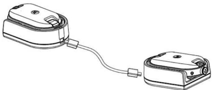
PpoceDypa
1 OTKIIOHTe BCE Ka6eJI (HAnpIMep, Ka6eJI NITaHnI nn Ka6eJI Micro USB) ot ODNHOmeCTbIX 3apAHyX yCTpoiCTB.
2 PoiKJIIOUHTe OINH KOHeC Ka6eJn JIa KIOHInPOBaHNc pa3bEmOM Micro USB K ODNOMy 3apAnHomy yCTpOInCTBy, a npYroN KOHeC - K dpYrOMy.

YBEIDOMJIENHE:
Y6eNTecb, YTO nepeKIOUaTeIb Ha Ka6ene IIN KIOHIpOBaHN yCTaHOBJIeH B noJoxKeHne Legacy (ycTapeBwne BepcN).
Bo Bpem npouecca knoHnpOBaHH naHoneCTbIe 3apnHbIe yctpoNCTBa He HxHO IOKJIIOuATb K cTeN 3JeKTPoNTaHH. AkkymyIaTOpbl He 3apXkaOTc. YcTaHaBnBaETCToJbKO CBa3b dAor oMeHa daHHbIM MeKdy paAnOCTaHcNMR.
3BknHHTe zeneByo paHIOCTaHIO n HOMeCTnTe ee B OdHOMeCTHOe 3apAHOe yCTPOIcTBO.
4TO6bIKHQUHTbNCXOHyopadnoCTaHnIO,ODHOBpeMeHHoHaXMTeu ydepxBaHTe KHOKNPTTn-HaNcXoHNOpaNoCTaHnI npn BKnIOyeHNpaoNOCTaHnIN,POKa He ycJIbIHTe TOHaJIbHbCnHAnKNOHPOBAHn.
5 YTo6bI HaataB npoueCC KNOHnPoBaHna, NOMEcTne NCXoNDHyO paDIOCTaHcNIO B ODNHOcTHoe 3apdHoe yCTPOINCTBO C ayDINOAKCECCyapOM, 3aTeM HAKMTe IN OTNyCTNTe KHONKY MeHNo.
B cnyae ycneuHoro BbINOJIHeHnI npO3ByHT ToHaJIbHbI CnHrAa YcNeuHoro DeICTBna.
B cnyae c60r npo3Bynt ToHaIbHbI CnHn HeycneuHoro DeiCTBna.
3BykoBoi cnHaJI 3ByuHr He 6oJee nTn ceKHyI.
6 BbIKIOHTe N BkIOHTe paIIOCTaHcH, YTO6bl nepeBecT IN B NOIb3OBAteNbckn peKIM, BBIDrN3 peKIMa KIOHINPOBaHnNo 3aBepseHn IpOeCCA KIOHINPOBaHn.

YBEIDOMJIENHE:
Ecnn paiooctaHnna HaxoNTcBpeKmE KIOHnpOBaHnA, yHKnA aBTOMaTHueCKORO OTKIOUeHn NtAHn He npImHeTc.
BepHyTbca K npoeccy
KloHnpoBaHnpe paDnOCTaHcNn Ha cTp. 39
5.3
KloHropoBaHne paAnocTaHcN C NOMOUsbMOHOrOMeCTHO 3apdHorO yctpoiCTBa
PpeBapnteIbHbte Tpe6oBaHHa:
-Полнocьюзаржкеньieakумлготьдя Каддяпогдяпсгн.
Mhoromecthoe 3apndoe ycTpoiCTBO cepn CLP.
- 06e paHocTAHm BbIKIIOHeHbI.
- IcxOHaH paIIOCTaHcHn: paIIOCTaHcHn, KOtOpYIO Tpe6yETcKIOHIpOBaTb.
-LeeneBa paAnocTaHnue: paAnocTaHnue,Ha KOTopyu BbInOnHReTcKoNIpOBaHne KOHpyaunncxOHOpaNoCTaHn.
PpoceDypa
1 TTo6blnepeBecTn NcXoDHyIO paAnOCTaHcIIO B pExMM KIOHIpOBaHH, OJHOBPMeHHo HaxMITE n yDePKNBaTe KHOKNPTN - Ha NCxOHDHO paAnOCTaHcIMn PnBkJIooHeHHn paAnOCTaHcIMn, NOKa He ycblWNTe ToHaJIbHbI CNrHaI KIOHIpOBaHH.
2 Tomecntte NcXoDHyu paAnocTaHnIO B OdIN H3 3apA HBx pa3beMOB C MetKoI CLONE.
3 BkIIOUHTe ueIeByo paIIOCTaHcHIO n IOMecTITe ee B 3apAHybI pa3bEm C MeTKO CLONE, nocJe Hero 3anyCTITE npoueecc KIOHIpOBaHHJ.
4 YtobHaayatb npoecc KnoHnpOBaHna, HaxMnte KNONky MeHIO Ha IcxOHOpaNOCTaHn. XcxOHaRaIOCTaHnI3daET ToHaJIbHbI CNrHaI HaayJa KNOHnpOBaHna.
5 TTo6bI aKTHBnPoBaTb paNocTaHcHIO, BbIKNoCHte N BKnOChte ee no 3aBepseHnn npoecca KNOHnPOBaHn.
6 Tto6bI cKnHOHPoBaTb dpyryo paAnocTaHcNIO, NOBTOpe DeIeCTBnC 3 no 5
7 TTo6bI BbInTu n3 peKIMa KIOHnPOBaHna Ha NCXoDHo paAnOCTaHcMn, BBIKHOuHTe paAnOCTaHcNIO.
PncyHOK 13:KnOHNPOBaHne paAnocTaHcN C NOMOUsbMHoromeCTHO 3apAHDoro yctpoiCTBa

BepHytbcK npoeccy
KnoHnpoBaHnne paAnocTaHcnn Ha cTp. 39
5.4
YcTpaHHe HEnoJaOK B pexnme KIOHnPoBaHnA
Korda n rde nCnoJIb3OBAtB:
PaHIOCTaHcIa NOdAcT OtpbBnCTbI rnyxOy 3Byk, O3HaauoIu, YTO npOeDpy KNOHIpOBaHIN BbINOHNtB He ydaIocb. B ATOM cIyae BbINOHNte KaKdoe n3 nepeUncJeHHbIX HnxKe DeJCTBNI pePONbIKo BbINOHNtB KIOHIpOBaHIne:
PpoceDypa
1 Y6eIntecb, yTo akKymyIaTOpbI o6eX paNocTaHcN IONHO 3apJKeHbI yCTaHOJIeHbI B paNIOCTaHcNIO npabINbHO.
2 PpOBepe Te noKnOueHne Ka6eJn IINr KIOHIpOBaHn K O6oIM OndHomeCTbIM 3apAHyBIM yCtpoiCTBaM.
3 Y6eHNTecb, YTO Ha 3apAHOI IIOUaIKe I HA KOHTAKTx paIIOCTAHuIN He cKoIINC MyCOP IN YTO KOHTaKtBip aIIOCTAHuIN IIOTHO KAcAOTcR KOHTaKTOB ODNOMEcTHOrO INM MHoromecTHOrO 3apAHOYCTPOIcTBA.
4 y6eHntecb, yTO CEJIeBa rpaIIOCTaHcNBAKIIIOueHa.
5 Y6eIntecb, yTO IcXoHaHpaDIOCTaHua HAXOHTcBpeXIMe KIOHINPOBaHna.
6 Y6eIntecb, yTo o6e paAnocTaHcun npHaJnxKAT K ODHOMy dHaana3OHy cactOT, ODHOMy perHOHy n IMeOt OdHy MOUHOCb nepeDaH.

YBEIDOMJIENHE:
3TOT Ka6eB nIg KNOHnOBoAHH npeHa3HaueH dIy pa6oTbI TOJIbKO C COBMecTUMbIMN ODNOMeCTHbIMN 3aprAHyIMN yCTpoiCTBaMn Motorola Solutions.
Pn3aKa3e KOMnneKta Ka6eJna IJI KNOHnPoBaHHa NcNoB3yIte HmOp no KaTalory HKKN4028.
Boone npOpoHyIO nHΦopMauio 06 akceccyapax cm. B pa3dJe Akceccyapbl Ha cTp. 57.
BepHytbcK npoeccy
KnoHIpOBaHHe paAnocTaHcHn Ha cTp. 39
Tna6
PacshinpeHHa konHcHypaunpaHpaHocTahn
PacunpeHHa KOnHpyaunpaNIOCTaHcNn N03BOJraT hAcTpaNBaTB npaMeTpbl n3 npdBaHTeBHO 3anporpammpoBaHHoro cncska 6e3 nCNoIb3OBAHNKOMnbTOpeA.
PekimpacunpeHHoKoHpyaunno3BOJraTnacpanBaTBcneyUune npametpb:
KaHaJIbI
- Yactotbl
KoDbI (CTCC/LUHJI)
C nomoIbIO npaMeTp aactotbMoXHO BbIbnpaT bactOy dIra KaJdoRo KaHana. NapaMetp KoBIO3BOJIeT MInHMn3NPOBaT bomexn, PpeIOCTaBJIra Ha BbIbOp HeCKoJIbKO KOM6Haucn KOIOB, KOtOpBleΦINbTpYIOT CTaTHueckne NOMEXN, Wym I HexKeNaTeNbHbe COo6uHnE.
CcbiKn no TeMe
IepexoB peximpaunpeHHoKoHpyaun paanocTaunnHa cTp.43
6.1
IepexoB B pexm paCunpeHNo KOnΦnrgpaucn paAdnoctaHcN
PpeBapnteIbHbIe Tpe6oBaHnIa:
Bbiknoute nntaHne paNocTAHm.
PpoaeDypa
1 OndOBpeMeHHo HaxMnte KhoNk PTt, + n KhoNky nItaHn ydepkBaIte nx B teueHne 3-5 cekyHd, noka He ycbluHte 3BykoBoi cnHaI n rOncoboe o6bAbeHne PeKIM nporpaMMnpoBaHn.
CBeToIIOHbI INHINKaTOP HaUHeT MmTaB 3eJIeHbIM CBeTOM.
2 UTo6bI BbI6paTb HAcTpOuKn, KOtOpBle Heo6xOaHMo N3MeHnTb, HaxMnte KhoNky MeHIO. Hxke nepeuNCneHb HAcTpOuKn, KOtOpBle MoXHO N3MeHnTb:
KaHAn (MnA MHOROKAHaJIbHbIX MoJeIeN)
- Yactotbl
Ko
Tolocobble 6bBHeHnHa3bBAHOT NyHKtMeHIO COOshaOT TeKUzne HaCTpoKn.
3 TTo6bI n3MeHnTb HacTpOyK, HaxKMTe KhONKy + nn -.
4I npnepexoanda K cneyouemy 3nmeHTy MeHn HaxmTe KhONky MeHO.
5 TTo6bI BbInrN 3peKIMa pacwnpeHHo KOnHpyaun paAnocTaun, HaxMnTe N ydepXnBaTe KONky PTT, noka He ycblwnte 3ByKOBoi CnHaJ.
MN006181A01-AB
Глава6:PacunpenHHaKoHmrgpaUma paMnocTaHcIM
BepHyTbca K npoceccy
PacupeHHa KOHcHpyaunpaHnOCTaHnHa cTp. 43
Tna7
He norpykaTe yctpoiCtBO B BOdy
He donyckaetc npimehene cnpTa nnn Hnctraux CpeCTB
EcnnpaHnOCTaHnna nonana B Body:


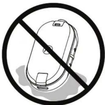
BbIKIOHTpe paIIOCTaHcHIO n 13BNEKTE aKKMyTApToBbl
Ppnte MrgkO cyxO TkaHbIO
He nCnOJb3yIte ycTpoIcTBO DIO NOnHOro BbICbIXaHIN

YBEDOMJIENHE:
PapnoctaHnna Hmeet Knaacc 3auntbI IP54 TOnbko B Tom cnyuae, ecn nblne3aunTHa Kpbuika nnayauoakceccyap noKNIoueHb I Ka3beMy.
Tnaba9
Ta6nncbI KODOB paNocTOT
B cIeDyUoJnx TabIuIax npBBeHa HOpMaunr O uactotax, KOTopra MoKet 6bITb non3Ha npn IcNoIb3OBAHn npHeMonepeDaIoox paIIOCTaHcN cepIN CLPe ot Motorola Solutions c dpyrmmpaiaocTahm6n3HeC-Klacca.
CcbiKn no TeMe
Cnncok yactot CLP446e Ha ctp. 49
YactoTbCLPePLUSHa cTp.50
KoIbI CTCSS/LUJI yCtpoiCTBa IJnI NCKJIIOUeHIna NOMex Ha cTp. 51
9.1
Cnncok yactot CLP446e
Ta6nua 12: Napametpb moedecl CLP446e no ymoJuaHHIO
| № частови Насторий частови (МГц) Полosa погоньая (кГц) |
| 1 446,00625 12,5 |
| 2 446,01875 12,5 |
| 3 446,03125 12,5 |
| 4 445,04375 12,5 |
| 5 446,05625 12,5 |
| 6 446,06875 12,5 |
| 7 446,08125 12,5 |
| 8 446,09375 12,5 |
Ta6nua 13:Дононштelve8чacToTдЯCLP446e uepe3 CPS
| № частOtы Настroduки частOtы (κΓι) Полosa погонская (κΓι) |
| 9 446,10625 12,5 |
| 10 446,11875 12,5 |
| 11 446,13125 12,5 |
| 12 446,14375 12,5 |
| 13 446,15625 12,5 |
| 14 446,16875 12,5 |
| 15 446,18125 12,5 |
| 16 446,19375 12,5 |
NacToTbHaCtpoKn HAcToTb (Ku) Noloca nponyckaHna (Ku)

YBEDOMJIENHE:
B Pocnn DeiCTByeT 3aKoHoaTeNbHoe orpaHnueHne Do 8 KaHaoB. NoyMOnuHaHIO doCTynbI ToIbKO aHaNoROBbie YacToTB B dIana3OHe 446,0-446,1 MfU. AHaNoROBbie YacToTB B dIana3OHe 446,1-446,2 MfCneDuY TcNObTaBb ToIbKO bTex CtpaHax, B KOTopbIX IN cNpOB3OBAHne pa3peSeHo n 3aKpePnEHO Ha yPoBHe OcNuaJIbHbIX NOCTAHOBJIeHNI.
BepHytbcK npoeccy
Ta6nui KoIOB n paIIOuOaCTOT Ha cTp. 49
9.2
YacToTbI CLPe PLUS
Ta6nua 14: YBv-chaToTbCLPe Plus
YacToTbMOxHNO 3MeHnTb T a6JIne YacToT Yepe3 IIO CPS.
| № частов Chacr (MГц) Понosa пponypsсан я (кгц) | № частов Chacr (MГц) Понosa пponypsсан я (кгц) |
| 1 464,5000 12,5 46 466,3375 12,5 | |
| 2 464,5500 12,5 47 466,3625 12,5 | |
| 3 467,7625 12,5 48 467,7875 12,5 | |
| 4 467,8125 12,5 49 467,8375 12,5 | |
| 5 467,8500 12,5 50 467,8625 12,5 | |
| 6 467,8750 12,5 51 467,8875 12,5 | |
| 7 467,9000 12,5 52 467,9125 12,5 | |
| 8 467,9250 12,5 53 469,4875 12,5 | |
| 9 461,0375 12,5 54 469,5125 12,5 | |
| 10 461,0625 12,5 55 469,5375 12,5 | |
| 11 461,0875 12,5 56 469,5625 12,5 | |
| 12 461,1125 12,5 57 462,1875 12,5 | |
| 13 461,1375 12,5 58 462,4625 12,5 | |
| 14 461,1625 12,5 59 462,4875 12,5 | |
| 15 461,1875 12,5 60 462,5125 12,5 | |
| 16 461,2125 12,5 61 467,1875 12,5 | |
| 17 461,2375 12,5 62 467,4625 12,5 | |
| 18 461,2625 12,5 63 467,4875 12,5 | |
| 19 461,2875 12,5 64 467,5125 12,5 | |
| 20 461,3125 12,5 65 451,1875 12,5 | |
| 21 461,3375 12,5 66 451,2375 12,5 | |
| 22 461,3625 12,5 67 451,2875 12,5 | |
| № чASTOTBIЧAST (MГц) ПОLOСА пponускан я (кГц) | № чASTOTBIЧAST (MГц) ПОLOСА пponускан я (кГц) |
| 23 462,7625 12,5 68 451,3375 12,5 | |
| 24 462,7875 12,5 69 451,4375 12,5 | |
| 25 462,8125 12,5 70 451,5375 12,5 | |
| 26 462,8375 12,5 71 451,6375 12,5 | |
| 27 462,8625 12,5 72 452,3125 12,5 | |
| 28 462,8875 12,5 73 452,5375 12,5 | |
| 29 462,9125 12,5 74 452,4125 12,5 | |
| 30 464,4875 12,5 75 452,5125 12,5 | |
| 31 464,5125 12,5 76 452,7625 12,5 | |
| 32 464,5375 12,5 77 452,8625 12,5 | |
| 33 464,5625 12,5 78 456,1875 12,5 | |
| 34 466,0375 12,5 79 456,2375 12,5 | |
| 35 466,0625 12,5 80 456,2875 12,5 | |
| 36 466,0875 12,5 81 468,2125 12,5 | |
| 37 466,1125 12,5 82 468,2625 12,5 | |
| 38 466,1375 12,5 83 468,3125 12,5 | |
| 39 466,1625 12,5 84 468,3625 12,5 | |
| 40 466,1875 12,5 85 468,4125 12,5 | |
| 41 466,2125 12,5 86 468,4625 12,5 | |
| 42 466,2375 12,5 87 468,5125 12,5 | |
| 43 466,2625 12,5 88 468,5625 12,5 | |
| 44 466,2875 12,5 89 468,6125 12,5 | |
| 45 466,3125 12,5 90 468,6625 12,5 |
BepHyTbcK npoeccy
Ta6nii KoIOB n paIIOvAcTOT Ha cTp. 49
9.3
KoДы CTCSS/цчл устpoиства дя nckliuoyehna nomex
Ta6nua 15: KoDbI CTCSS/LUJ yctpoiCTBa Ia ncknoueHna nomex
| CTCSS KoД CTCSS/ | KoДЦПКoДЦПКoДЦПКoД |
| ЦП | |
| 0 OТклоче | 24 151,4 47 54 71 243 95 445 |
| Hо | |
| 1 67,0 | 25 156,7 48 65 72 244 96 464 |
| 2 71,9 | 26 162,2 49 71 73 245 97 465 |
| CTCSS KaD CTCSS/ цчл | Код цчл Код цчл Код цчл Код |
| 374,4 27 167,9 50 72 74 251 98 466 | |
| 477,0 28 173,8 51 73 75 261 99 503 | |
| 579,7 29 179,9 52 74 76 263 100 506 | |
| 682,5 30 186,2 53 114 77 265 101 516 | |
| 785,4 31 192,8 54 115 78 271 102 532 | |
| 888,5 32 203,5 55 116 79 306 103 546 | |
| 991,5 33 210,7 56 125 80 311 104 565 | |
| 1094,8 34 218,1 57 131 81 315 105 606 | |
| 1197,4 35 225,7 58 132 82 331 106 612 | |
| 12100,0 36 233,6 59 134 83 343 107 624 | |
| 13103,5 37 241,8 60 143 84 346 108 627 | |
| 14107,2 38 250,3 61 152 85 351 109 631 | |
| 15110,9 122 69,3 62 155 86 364 110 632 | |
| 16114,8 39 23,0 63 156 87 365 111 654 | |
| 17118,8 40 25,0 64 162 88 371 112 662 | |
| 18123,0 41 26,0 65 165 89 411 113 664 | |
| 19127,3 42 31,0 66 172 90 412 114 703 | |
| 20131,8 43 32,0 67 174 91 413 115 712 | |
| 21136,5 44 43,0 68 205 92 423 116 723 | |
| 22141,3 45 47,0 69 223 93 431 117 731 | |
| 23146,2 46 51,0 70 226 94 432 118 732 | |
| 119734 | |
Tabnca 16: KoBc CTCSS/LUJ yctpoiCTBa Iy NckloueHn nomex (npoDOnjKeHne)
Aktiveras via CPS (Customer Programming Software).
2.8
Välja kanaler
Procedure:
1 Tryck på Menu-knappen (Meny).
Du hörettrostmeddelande om attandra kanalen med antingen (+) ellr(-).
2 Valj onskad kanal.
Lysdioden anger den nya kanalens farg.
Radioprogramming via CPS
Tabell 8: Standarder for CLP446e
| Kanalnummer Installierung gar für frekvensband (MHz) | Kodvärde (Hz) Bandbreed (kHz) | ||
| 1 446,00625 67,0 12,5 | |||
| 2 446,01875 | |||
| 3 446,03125 | |||
| 4 445,04375 | |||
| 5 446,05625 | |||
| 6 446,06875 | |||
| Kanalnummer Installnirg für frekvensband (MHz) | Kodvärde (Hz) Bandbredd (kHz) | ||
| 7 446,08125 | |||
| 8 446,09375 | |||
Tabell 9: Ytterligare atta kanaler/frekvenser for CLP446e via CPS
| Kanalnummer Installnirg für frekvensband (MHz) | Kodvärde (Hz) Bandbredd (kHz) |
| 9 446,00625 DPL754 12,5 | |
| 10 446,01875 | |
| 11 446,03125 | |
| 12 445,04375 | |
| 13 446,05625 | |
| 14 446,06875 | |
| 15 446,08125 | |
| 16 446,09375 |

| Model Tahmini Pil Ömrü | |
| CLP446e 20-SAAT | |
| CLPe PLUS 18-SAAT |
3.3
Li-Iyon Pili Çıkarma
On kosullar:
Seikl 7: Bagimsiz Pil

LED yesil yanip söner.
2 Deigistirmek istediginiz ayarli semek icin Menu dugmesine basin.
3ACTEPEXEHH: TpBaNnI rynn I yb-koTO NOxOJKeHH MoKe TmUacBO a6o Ha3aBxN nOwKOuNTn cny. 10 Bnuy rnuHicTb padionpncToHO BCTaHOBeHO, To MeHsue acy HMM MOxHa KopNCtYBaTnC 6e3 pnsKny dner cnyxy. NOripSeHH Cnyxu Ypee3 rynn I yM He 3aBxN BnRABnEeTbcra Opa3y, BOHO MoKe po3BnBaTnc NoCTyNoBO.
Y HbOTo MoXHa 3'AcyBaTn Taki NItaHHA:
-Чадостуни на радюпстол nonepeньо зарогамови Канал?
- KIMM KHOKNKAMN CKOPNCTaTNCa DnA OTpMaHHa DOCTyNy Do IHxN xFyHKui?
-ЯкakcescuapmMOkyTb6yTNKOpNCHMn Bam?
-Як eфektubHo kOpncTyBaTnscra paДionpncTpoem?
- Jaki 3axoDi texHicnO o6cnyroBvBaHHaDonomoxyTb 36ilbUnTI TepMIn cnyk6n paiaocTaHii?
Bmict komnneKty
Leu po3in mictnb BIDOMOCTI npo KOMnneKTAuio paionpncpo.
Baw KOMnneKt MICTb HabeDeH HiXHe BnO6n Noci6HnKn.
-Пистрий ДвocToPoHHbOro paIIO3B'ЯЗу cepiCLPe
- OXOJI i3 NOAChNIM 3aTnCKaUeM
-Лити-ioHHnakymyIaTOpiknkaBiciciKdЯakymyIaTopa
3apnpi-niCTaBka 3 TpaHcOpMaTOpom
-Aydioakcecyap
-3aTnUkaДЯaydiop03'Emy
Kopotkn noci6nik i3 BnKOpncTaHH, 6poWpya 3 6e3neHoro BnKOpncTaHHra paioacToT, nctibKa npo BiinobiHicTB DnpeKTNBi npo paioTeXHiHe obnHaHH
ДokнадиWI BiDOMOCTI npo Bnpo6n DnB. Na Be6-caTi https://learning.motorolasolutions.com.
Y zuomy noci6nky KopncTyBaça onucaHo HauBeHe Hi NkXe MoJeI.
YcTaHOBJIeHHaKymyJrToPA
PpoceDypa
1 3cyhBe Bropy pfikcatop Ha Hxkiy qactnHi KpnuKn rHizda akymyIaTopa n 3HIMtB KpuiKy BiDciky dna akymyIaTopa.
2 Po3aTyTe KOHTaKtN aKymyIaTopa BiIDnOBiDNo Do KOHTaKtIB y BiDcIky.
3 CnoaTky BCTaBte CTopoHy akymyIaTopa 3 KOHTaKTOM, a NOTIM HaTNCiTb Ha akymyIaTOp, 0o6 HadiHIO NOrO BCTaHOBNTN.
4 YcTaHOBt b Ha Micuie KpuKy BiDciKy akymyTopa NocyHbTe fikcatOp DOHN3y, 0o6 3aMKHyTI ii.
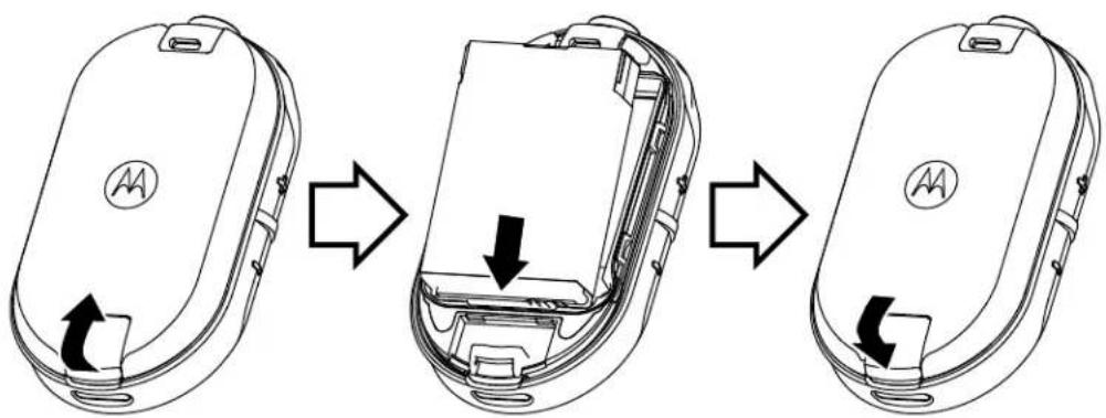
Pnc.2:YcTaHOBJeHHaKymyIaTopa
2.2
Пд'эннг дротовoro aydioakcecyapa
IpeedyMoBn:BumKHiTb paionpncTpii.
PpoceDypa
1Пд'снайе ayioakcecyapdo po3'emyB paionpncptoi TAKIM YHOM,no6 no3haka po36nokybaHHa akcecyapi 6yna cnprMOBaHa do nepeHbOi naHeni paionpncpto. PepeKohaiTecra,io iHdkatop Ha ayioakcecyapHa paionpncptoi cymiuehi.
2 O6eTaNTe po3'Em ayidioakcecyapa,doKn no3HaKy po3bIokyBaHHa Ha akcecyapi He 6yde cnPMABOHDo npeHboi naHeni paionpncTpOIO.
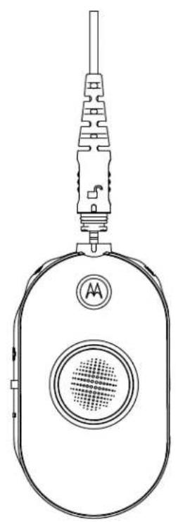
Pnc.3:Pi'd'eHaHHa pOToBOro ayioakcecyapa

3YbIMKHiTb paionpncTpH
4 HaTnCHiB KONky CTaHy akMyJyTopa, MeHHOa6o peryIIOBaHHra yHocTi, 0o5 nepeBipuTHn HABHICTb 3ByKy B ayioakcecyapi.
Tabn. 1: KoHphiRpyaizj Bepxhix cbITIOIOIDHX iHdNkAToPiB, KOJI npOTOBn ayioakcecyap He niiEHaHO a6o BiD'EDHyETbcra
YbIMKHeHHa Ta BmKHeHHpaioctaHci
PpoceDypa
1 Lio6 yBIMKHytn paionpncTpni, HATNCHt b i BTPMMyTe KHONky XNBLENHn aKymyIaTopa, DOKn He noCyTe KOpOTkn CnHaT Ta He 3arOpNTcbc KInbue-iHnKaTOp Smart Status Glow.
2 5o6 BmKHyTn paiaionpncTpi, HATNCiB i BTPMMyTe KhoNky XNBHeHn aKymyIaTopa, DOKn He noyTe kopoTKn CnHaan, a KInbc-e-iHdkaTOp Smart Status Glow He 6nIMHe Odnh pa3.
2.4
Perguobannr rychocti
PpoceDypa
Ucbomy po3diOni OncaHO KepyBaHHHaJaHTyBaHHMaMeHIO.

YBAGA:
He o6oB'3koBO npocnyxobvBaTu ronocoby nikka3ky do kiHcy, nepu HIX haTnCKaTu HaCTynHy KhoNkY.
Ipe6yBaOnu B pexmMi MeHIO, KopoTko HATnCHiTB KhoNky PTT a6o 3aueKaIte 3 cekyn dna BxOxy 3 MeHIO.
PpoceDypa
13miheHHKaHJIb
a HatncHtB KhoNky MeH, 06 nepeTn do BkJaKn Channel (KaHaJ).
b HaTnCKaTe KhoNKn (+) i (-) nla 3MiHeHHKaHaJIb.
2 IepexiD opekmy MoHiTopnHy
a HatncHtB KONky MeHo, 06 nepeuTn Do BKJaKn Monitor (MoHiTopnHr).
b HatncHtB KhONky (+) a6o (-) Iy BIDNOIHO AKTBAuii YI DeaAKTBAuippeKIMMy MOHiTopnHy.
3IpepeixidopexkmycKaHyBaHHa
a HaTnCHiTB KHOJky MeHIO, 106 nepeeTN Do BKnAdkn Scan (CkaHyBaHHra).
b HaTnCHiTh KONky (+) a6o (-) IINBIOIHO AKTUBauiy nn DeakTBAuipexmmy cKaHyBaHHra.
4HaCnlaHnToHaNbHorBnKnky:
a HaTnCHiTb KOnKy MeHIO, 0o6 nepeeTN Do BkJaAdkn Call Tone (ToHaJIbHm BnKlnK).
b HaTnCHiB KONky (+) a6o (-) nIy HauCINaHnToHaJIbHO BKNKNIky.
Актугetically за дожиморою komп'tут Ephoro порамного забeэпченидлу порамваши Customer Programming Software (CPS).
2.8
Bn6ip paiokahanib
Ppoueypa
1HaTnCHiB KhoNky MeHIO.
Bn noyete roiocoby niikka3ky 3 iHctpykuieIO haTNCHTKHOKNy (+) a6o (-), 06 3miHHTN kaHaJI.
2Bn6epiTb noptpiHn kaHaJ.
CbitIOIOHN iHnKaTOp BiO6paKye konip HOBOro KaHaNy.
3 HaTnCHiB KONky PTT nIaNTBepdxKeHHa, a6o KaHaan AKTNByeTbcra Ype3 Tpr CeKyHn.
2.8.1
HanaaHTyBaHHa KaHaIy 3a 3aMOBcYBaHHaM dIa CPS
Y ciu Ta6nui OnncAo HanaaTyBaHHKaHany 3a 3amOBuyBaHHm dny KOMnIOTePHoro nporpaMHO 3abe3neueHHn nn nporpaMByaHH Customer Programming Software (CPS).
Ta6JI. 3: HanaWtYBaHnKaHany dny CPS
| CLP446e5 i modéli CLPe PLUS | ||
| Канал Стан світлodіODного | iIndikatopa | KoIP |
| 1 Уер党支部 | ||
| 2 Зелени | ||
| 3Жов tym | ||
| CLP446e5 i myděni CLPe PLUS | ||
| Kanaj Stanh cbiTlndiOndnoro | iHdnikatopa | KoJip |
| 4 ŠblakHTnI | ||
| 5 ΦiOleTOBNI | ||
| 6 BiIn | ||
| 7 ŠblakHTnI | ||
| 8 Помаранчеви | ||
| 9ЧервOnI | БiIn | |
| 10 3eJIenI | БiIn | |
| 11 JxOBtNi | БiIn | |
2.8.2
IooB BnInT3 KaHaJy nepeDaBaHHB NkNky, NOKu Yac 3aTpUMKn He CnINHyB, KOPOTKO HaTNCiTb KHONKy XNBHeHHa MeHIO abo DOBro HATNCiTB KHONKY MeHIO.
Pozhin 3
AkymnyTop i 3apaHn npncTpi
U cybomy po3dini onucaHo xaapkTepcntnKn akymyToppa n 3apndHoro npncptoBaoi paioctanii.
3.1
XapaKTepeNCTnKn aKymyJIaTOpiB
Papionpncpii noctaaybcs B kOmnnekti 3 nii-i-oHHm akymyIporom. Npeed noaTkom BnKOpncTaHHA akymyIaTopa Ioro Heo6xIDHO 3apraHTn, 0o6 3a6e3neuHTn ONTMaNbHy eMHicTB i efeKTNBHICTb.
Pecypc akymlyaTopa Bn3Hauaetbca DekiIbKOMa fakTopamn. Hai6ilbwe Ha hBoro BnIbBaIOtbepe3apdJxHa n rnn6hna po3prdxehnra. 3a3Bnua, 70 6iIbwnn HADNIWKOBI 3aprd OTpIMye npnad i 70 rnn6he Bin po3prdxaeTbcra, To MeHne cIKNIB 3apdJxHaHHRA-PO3prdxAHnBnTPMaAcymyIaTOp. Hanpiklnd, AkymyIaTOp, 70 OTPmYe HADNIWKOBI 3aprd i NOBHCTO pO3prdxAeTbcrdeKlbka pa3ib Ha deHb, BnTpMaE MeHwe cIKNIB, HIX AkymyIaTOp, kNPI dWe nepe3apdJxKaetbcn 70oENHO po3prdxaeTbcra IINHe Ha 50%. AkymyIaTOp, 70 MaJxHe HIKOIn He nepe3apdJxCaetbcn IPO3prdxAeTbcB C cepedHbomy Ha 25%, cnkyntme ue doWBie.
Akymylantopn Motorola Solutions po3p6bnei cneiaJIbHO nIBy BIKOPncTahHcymicho 3ap4nHmnpnCTPOrIM KOMnAHII Motorola Solutions, kI, y cBOIO uepy, np3NaHei came dIy 3ap4xHaHH TaKnxakymyIaTOB.3Ap4xHaHH akymyIaTOB 3a DOONOMOIO o6IaNHaHH iHux BINObHKIB MOXepn3BeCTn Do NOWkoJKeHH akyMyIaTOB i CKacyBaHHra pAHTIi Ha akyMnyIaTOB. HAMaraiTeCeNIDTPMByATn TEMpePAtpy akyMnyIaTOB HA pIBHI KIMHaTHOI TEMpePAtpy, To6To 25^ (77 F).3Ap4xHaHH OXIoJKeHHo akyMnyIaTOB (HIXcE 10 ^ C a60 50 ^ F ) MoKe CTaTN npuHNO BVtOKyeNEkTPOJIty, a B DeAKnBnAdkax HabITb BHXOy akyMnyIaTOB 3 naDy. 3Ap4xKaHH NeperpIToro akyMnyIaTOB (TEMpePATOIO NaAD 35 ^ C a60 95 ^ F ) np3BONDtB do 3HIXeHH NOrO eMHOCTi,HERATNBHO BNINBAUOn Ha EKCNIyatauHi xapaKTepNCtIKn paioNPcSTPOIO. DInr 3a6e3neueHH ONTMaJIbHnx TEMpePAtpyHx yMOB 3ap4xKaHH akyMnyIaTOB pINCTPOI dN IWBnKO rO 3ap4xKaHH, BINObNeHoi KomnaiHcEO Motorola Solutions, obnaHaHO daTukkamn TempePAtpy.
3.2
Yac po6oTn akymyIaTopa
Y tabni ci HnKHe HabeJeHO BiDOMocTi npo pecypc akymyTopa dny 5% nepeDaBHH, 5% npiomy, 90% peKmMy ouikBaHn (CTaHdapTHn po6ouh LKn).
Ta6J. 4: Ipn6Iln3Hn qac po6Otn akymyIaTopa
BnMaHnIiTi-IOHOro aKymyJTopa
IpeedyMoBn: IpeebipTe, YI BBIMKHeHO paiaocTaHciIO.
PpoceDypa
1 3cyhBe Bropy pfikcaTop Ha HxHHi YactnHi KpnuKn rHizda akymyIaTopa n 3HIMtB KpuiKy BiDciKy dna akymyIaTopa.
2BHTHbakMyJrTopi3paionpncTroIO.
Pnc.5:3HHTaakymyIaTOPa
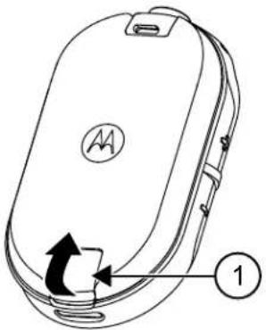
| Homepo3nziIOnnc | |
| 1ФikcaTOpakymyIaTopa |
3.4
Блok XXIVBJIeHЯ,адanTep i 3apYdHn npncTpii-niDcTaBka
Papionpncptpi nocataeBcB KOMnJIeKti i3 3apAHHM npNCtpoem-niDCTaBkoH, o6laHaHm TpaHcΦopMaTopoM.

YBAGA: NIIe dIy MoIeNe, IIO HAdcunauTbcra OkpeMMKOMnKeTAMN (He B rpynoBI ynaKoBu).
BiDomocTi npo akcesCyapn DnB. y po3diI AkcesCyapn Ha cTOp. 52.
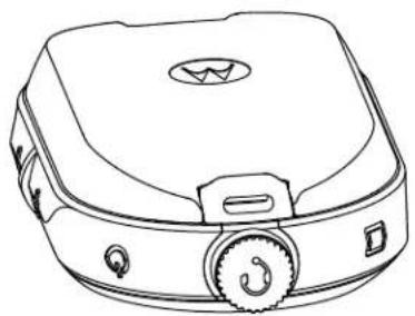
Pnc.6:BnokXnBneHnnaaandepi3apAHHnpucpi-nidctabka
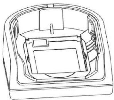
3.5
AkymnyTop okpeMo
AkyMnyIaTOp MoJHa 3apJxKaTn OkpeMo.
AkymyIaTOp MoxHa 3apJxKATn OkpEmo 3a DonomoroOdHomichoro a6o 6araTomichoro 3apJHoro npucToIO.

YBAFA: Y pa3i npnd6aHHI DOdaTkoBnX 3apdHnx pncTpoIB a6o 6JokB JNBEHNEHNEpekoHaTeCra, IIO BOHN cymiHi 3 HaeBHUM 3apdHmN pncTpoMn-iiCTaBkAMN 6JOKAMN XNBHeHH. DOKlaHHiU y InΦopMaui Ipo akceCyapn DVB. y po3di AkceCyapn Ha cTOp.52.

Pnc.7: AkymyIaTOp OkpeMo
| Homepo3niiОпс | |
| 1 Порт microUSB |
3.5.1
3apjaHnnaKymyIaTopa B OndHomichomy 3apdHomy npncTpoi-nidctabci
PpoceDypa
1IIO 3apAHTN akymyTTop, BCTaBTe po3'EM 6noka kNbJIeHnB B nOpT Micro USB ha nepeDhbomy 6ozi 3apAHorO npncToHO-niCtABKn.
2PiKIOHITb6NOKXNBNEHHAo pO3eTKM3MiHHO cTpymy.
3 BCTaBTe akymyIaTOp y rHizIO TaK, 106 BHyTpiiHII 6IK akymyIaTopa 6yNo cnpraMoBaHO Ha nepeDnIO nAHeNb 3apdHOrO npicToPO. DInB. AkymyIaTOp OkpemO Ha CToP. 26.
4 NepekoHaTeC, 10 KOHTaKTH akyMylTopa npnIraIOTb DO KOHTaKtIB 3apIHO rnpCTpoIO.
3.5.2
3apxHnHaKymyIaTopa OkpeMo BiD paiaocTaHcii B 6araTomicHomy 3apHOMy npncptoi-niIdctabci (doataKobe o7aHaHH)
PpoceDypa
1 Po3aTyIe 3apAHy npiNCTPiHa nnackn nobepxHi a6o yctahOBiTb noHO h CTHI.
2 BCTaBTe Ka6eJIb XINBnEHHy rHIsIO 6araTomicHoro 3apAHorO npncToIO.
3ПiДКнИчITь ka6eJIbdo po3eTkn 3mIHHorO cTpymy,a noTIM -do 3aprIHoro npucTpko.
4 BCTaBte akymyIaTOp y 3apJdHe rH3do TaK, uo6 BHyTpIuHi 6iK akymyIaTopa 6yNo cnPraMoBaHO Ha nepeDnIO nAHeNb 3apJdHOro npunctpo.
5 NepekoHaTeC, 10 KOHTaKTH akyMylTopa npnIraIOTb DO KOHTaKTIB 3apIHO rnpCTpoIO.
3.5.3
Pπu6πn3Hn yac 3apdkaHn
Y 3a3haeHnKHe Ta6nueyka3aHO np6n3nHn yac 3apxKaHH akyMnyTopa.
Ta6J.5:Pn6H3nH yac 3apxJxHn
Ta6n.7:CTaH aKymyIaTopa
2 Lio6 Bn6paTn HanaWtBuHnH, kI NOTpi6HO 3mHnTn, HATNCiTB KONky MeHIO.
Bn moKeTe 3miHHTn HabeDeHi HxKHe HaIaTuBaHHa.
KaHaI -ДЯ moJel' i3 NiTpIMKOIO KijbKoX KaHaJIIB
- Yactota
KoI
TOnocobicnoBiuueHHN NOiIDomnYb npo AKTNBn NapameTp i Ioro nOTOHe HanaTuBaHHa.
3 Lio6 3miHHTn HanaIaHTyBaHHra,HaNTCHiTb KHOJky + a6o -.
4Ioo nepeuTn Do HAcTyNHorO nyHKTy MeHIO,HaTCHITb KHONKy MeHIO.
5 506 BnTn 3 pexmmy po3wnpehoi konphiirpaqip aio, HATNCHTb KONKy PTT i BTPMnyTe ii, DOKn He npolyhae 3BykOBn CnHan.
Pozhin 7
ucyHeHnHeCnpaBHOCTe
Y Ta6nui HnxyHe HabeJeHO Bka3iBKn 3 ycHyHRe HecnpaBHOcte.
7.1
O3nakn HecnpaBnocte i piweHna
Ppoueypa
1
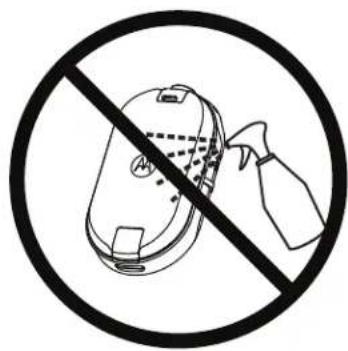
He BUKOPNCTOBYIte CnIPT a6o MMHI 3ac06n
Kaio do paiaionpuictpo noTpannna Boda
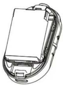
BmKHiTb paIionpncptpi i BnMiTb akMyJrTOP.
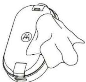
PpTb cyxOIO TkaHNOIO.
He BnKOpNCToBnyTe paiaionpncTpi,doKn BIn NOBHicTHe BnCOxHc.

YBAGA: Paionpncpii Mae Knaac 3axncty IP54, NIIe KOJI Do po3'emy BCTaBneHO nnno3axnchky kpiuky a60 ayioakcecayap.
Pozhin 9
TaNnca nnpobnx yactot i koidiB
Y tabnux HnKxue HabeJeHO dani 1oO yactOT, nortpi6Hi Ira BnKOpncTaHHn npicTpoIB dna DBOCTOPOHbOro paio3B'aycepi CLPe bD Motorola Solutions 3 iHmMn KomepuiHmnpaionpncToPMN.
9.1
Cnncok yactot CLP446e
Ta6JI. 12: HanaTuBaHHa 3a 3amOBuBaHHm MoJeI CLP446e
Tabl. 18: AkymyIaTOpn
Ta6JI. 20:3a4pHi npicrpoi