HT 2020 F - Pressure washer EINHELL - Free user manual and instructions
Find the device manual for free HT 2020 F EINHELL in PDF.
| Product type | High-pressure cleaner |
| Brand | Einhell |
| Model | HT 2020 F |
| Maximum working pressure | 115 bar |
| Maximum water flow | 5.5 L/min |
| Power supply | 230 V ~ 50 Hz |
| Motor power | 1.8 kW |
| Maximum inlet temperature | 60 °C |
| Maximum inlet pressure | 10 bar |
| Weight of the device | 13 kg |
| Sound pressure level | 70 dB(A) |
| Detergent tank capacity | 0.5 L |
| Nozzle type | Adjustable head (flat/point jet) + rotary nozzle (accessory) |
| Recommended extension cord length | Up to 25 m: cross-section 3x1.5 mm²; up to 50 m: cross-section 3x2.5 mm² |
| Safety system | Safety valve/pressure limiter, motor circuit breaker |
| Periodic maintenance | Cleaning of the intake filter every 50 operating hours |
| Warranty | 12 months |
| Intended use | Cleaning of vehicles, machines, buildings, etc. |
| Frost protection | Rinse with a mild/non-toxic antifreeze before winter storage |
| Recoil force on the trigger gun | 14.3 N |
Frequently Asked Questions - HT 2020 F EINHELL
User questions about HT 2020 F EINHELL
0 question about this device. Answer the ones you know or ask your own.
Ask a new question about this device
Download the instructions for your Pressure washer in PDF format for free! Find your manual HT 2020 F - EINHELL and take your electronic device back in hand. On this page are published all the documents necessary for the use of your device. HT 2020 F by EINHELL.
USER MANUAL HT 2020 F EINHELL
GB Operating Instructions High-Pressure Cleaner
text_image
n = schwarz b = weiß a = blau r = rot 230V/50Hz 220V/60Hznatural_image
Illustration of hands using a tool to adjust a mechanical component (no text or symbols present)natural_image
Hand holding a mechanical component with a downward arrow indicating motion (no text or symbols)D
natural_image
Illustration of hands assembling a mechanical component with a threaded connector (no text or symbols)natural_image
Illustration of a hand using a handheld device to interact with a tool, showing motion arrows (no text or symbols)natural_image
Technical illustration of a cable connector with two views showing internal structure and assembly (no text or symbols)natural_image
Illustration of hands adjusting a mechanical component with a tool, no text or symbols presentnatural_image
Diagram of a mechanical device with rotating components and directional arrows (no text or symbols)natural_image
Illustration of hands using a screwdriver to adjust a mechanical component (no text or symbols present)
natural_image
Illustration of a hand holding a screwdriver with an arrow indicating the process (no text or symbols present)Please read these instructions carefully before installing and operating the high-pressure cleaner.
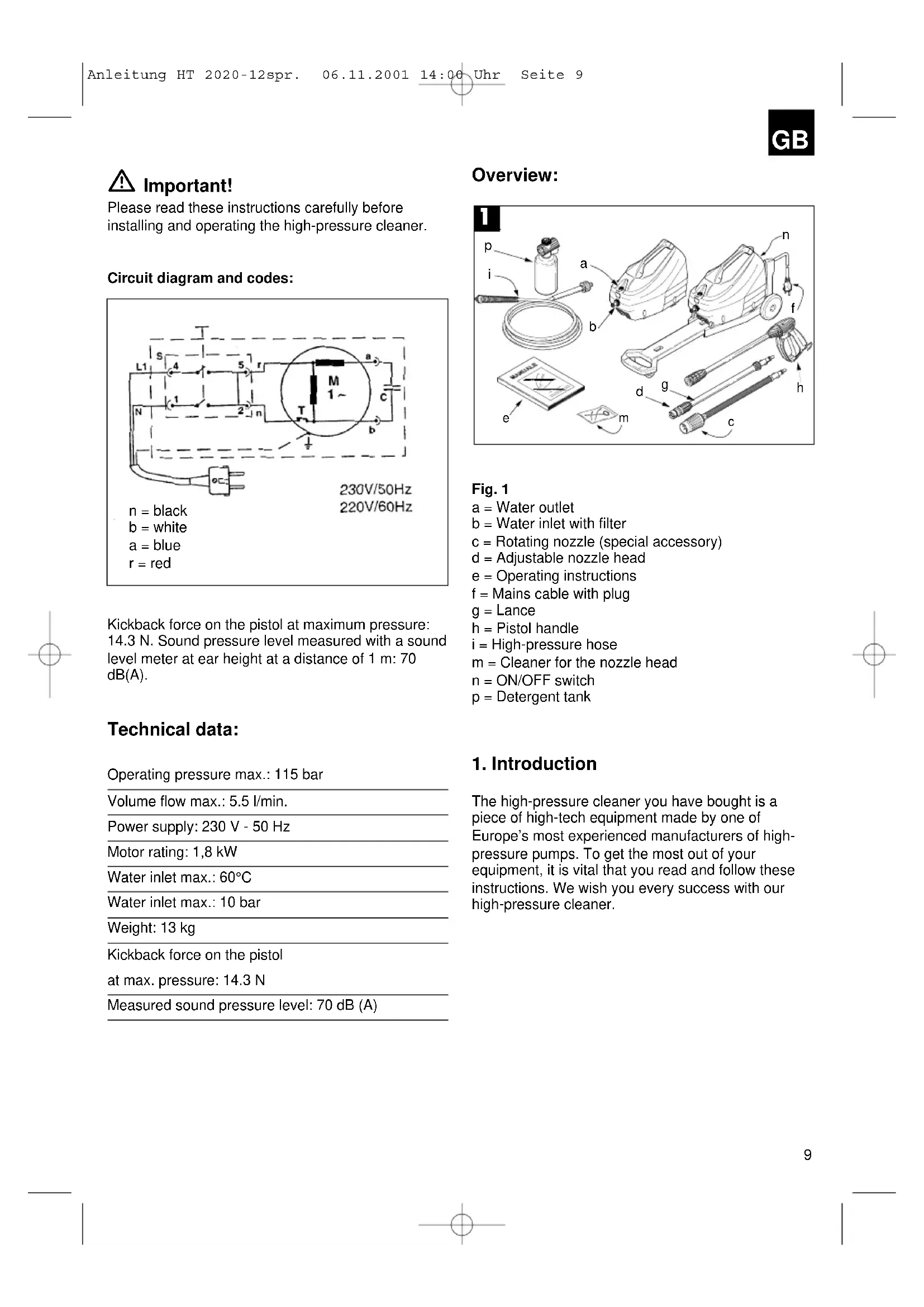
Circuit diagram and codes:
text_image
L1 S 4 5 r M 1~ a N 1 2 n T b c 230V/50Hz 220V/60Hz n = black b = white a = blue r = redKickback force on the pistol at maximum pressure: 14.3 N. Sound pressure level measured with a sound level meter at ear height at a distance of 1 m: 70 dB(A).
Technical data:
Operating pressure max.: 115 bar
Volume flow max.: 5.5 l/min.
Power supply: 230 V - 50 Hz
Motor rating: 1,8 kW
Water inlet max.: 60°C
Water inlet max.: 10 bar
Weight: 13 kg
Kickback force on the pistol
at max. pressure: 14.3 N
Measured sound pressure level: 70 dB (A)
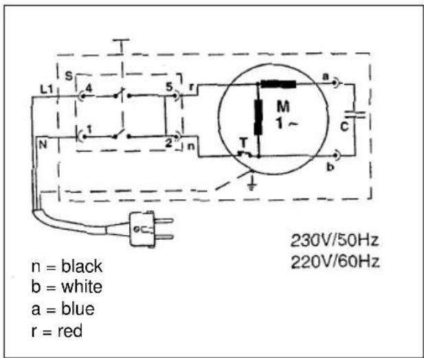
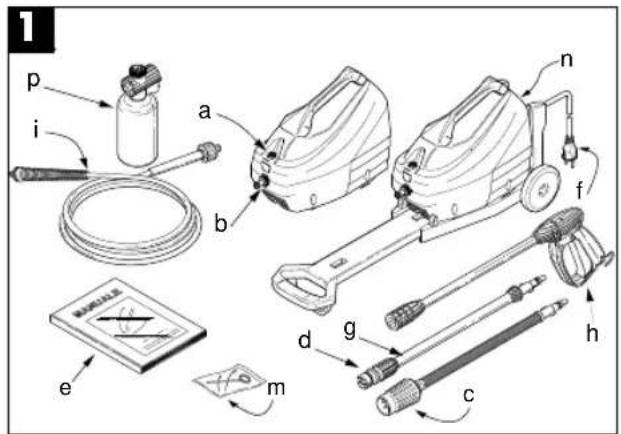
Overview:
text_image
1 p i a b n f e m d g c hFig. 1
a = Water outlet
b = Water inlet with filter
c = Rotating nozzle (special accessory)
d = Adjustable nozzle head
e = Operating instructions
f = Mains cable with plug
g = Lance
h = Pistol handle
i = High-pressure hose
m = Cleaner for the nozzle head
n = ON/OFF switch
p = Detergent tank
1. Introduction
The high-pressure cleaner you have bought is a piece of high-tech equipment made by one of Europe's most experienced manufacturers of high-pressure pumps. To get the most out of your equipment, it is vital that you read and follow these instructions. We wish you every success with our high-pressure cleaner.
GB
2. Safety regulations

Warning:
●Never use the high-pressure cleaner with inflammable, toxic or other such liquids as could impair the correct operation of the high-pressure cleaner. Risk of explosion or poisoning!
●Never direct the water jet at persons, animals or plants.
●To avoid the risk of electrical shock, never direct the water jet at the machine itself, at electrical parts or other electrical equipment.
●Never use the high-pressure cleaner in the rain. Risk of short-circuiting!
●Never allow the high-pressure cleaner to be used by children or unauthorized persons. Risk of injury!
●Never touch the plug or socket-outlet with wet hands as this could result in electric shock!
●Never operate the high-pressure cleaner when the mains cable is damaged. Risk of electric shock and short-circuiting!
●Never operate the high-pressure cleaner with a damaged high-pressure hose. Risk of bursting!
●Never lock the pistol trigger in the ON position. Risk of injury!
●Never change or adjust the setting of the control valve. Risk of bursting!
●To avoid malfunctioning, never change the original diameter of the water jet.
●Never leave the high-pressure cleaner unattended.
●To avoid the risk of short-circuiting, do not carry the high-pressure cleaner by the mains cable.
Safety precautions
●To avoid short-circuiting, all live parts must be protected against the water jet.
- Connect up the high-pressure cleaner only to an approved, earthed power source. An earth-leakage circuit-breaker (30 mA) will provide additional personal protection.
●As the high pressure can cause parts to rebound, always wear protective clothing and goggles when operating the machine.
●To prevent the high-pressure cleaner from starting up by accident, always disconnect from the mains before doing any maintenance or repair work on the machine.
- As the high-pressure jet has a kickback effect, make sure you have a firm hold of the pistol when pressing trigger.
- Observe the regulations of your local water board. Under DIN 1988, the high-pressure cleaner can be connected up to the drinking-water supply only if the feed pipe is fitted with a safety device to prevent backwater with drainage.
●The electrical parts must be serviced and repaired only by a qualified electrician.
●Always release the residual pressure before disconnecting the hose from the high-pressure cleaner.
●Make sure the screwed parts are screwed on tightly and check the other components of the high-pressure cleaner for damage or wear and tear both before use and at regular intervals.
●Make sure that people and animals do not come within 15 m of the high-pressure cleaner when in use.
3. General regulations
Please keep these instructions carefully for future reference.
●Before switching on the high-pressure cleaner, make sure the water supply is in good working order. Dry running will cause serious damage to the seals.
●Never pull on the mains cable in order to remove the plug.
- If the high-pressure cleaner is too far away from the objects to be cleaned, do not move it by pulling the high-pressure hose but instead use the handle provided.
●To avoid damaging the seals, do not operate the high-pressure cleaner for longer than 1 minute when the pistol is closed.
●In the winter months, store the high-pressure cleaner in a frost-free place.
●Make sure the air vents are not blocked when operating the machine.
- The cross-section of the extension cable must be in keeping with the length, i.e. the longer the lead, the thicker the cable must be. Furthermore, use only cables of the protection type „IP X 5“. The exact values are listed in the table.
GB
Motor:
Voltage 230V \~ 50Hz
| Extension up to 25 m cross section 3 x 1.5 mm | 2 |
| Extension up to 50 m cross section 3 x 2.5 mm | 2 |
Voltage Volt 100-115
| Extension up to 25 m cross section 3 x 2.5 mm | 2 |
| Extension up to 50 m cross section 3 x 4 mm | 2 |
●Use the high-pressure cleaner near the water supply in question.
●The packing materials can be recycled and must therefore be disposed of in compliance with the prevailing regulations.
- The high-pressure cleaner may be operated only with the manufacturer's original accessories and spare parts. The use of original parts is at the same time a guarantee for the safe and fault-free operation of the high-pressure cleaner.
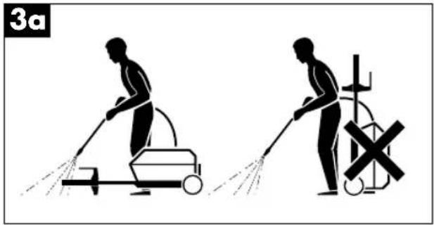
●The high-pressure cleaner may be operated only in a horizontal position.
text_image
3aApplications
●The high-pressure cleaner is intended exclusively for the cleaning of vehicles, machines, boats, buildings etc. from which it removes stubborn dirt using a jet of clean water and chemical detergents.
●Use only chemical detergents which have been proven to be biodegradable.
●Vehicles may be cleaned only on premises equipped with the necessary oil separation system.
Safety system
The safety valve also functions as a pressure limiting device. When the pistol is closed, the valve opens and allows the delivered water to circulate in the pump.
4. Installation
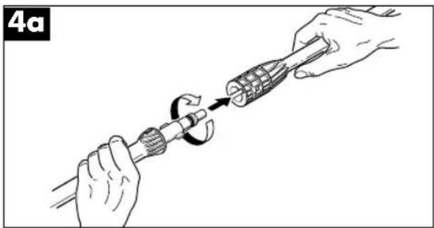
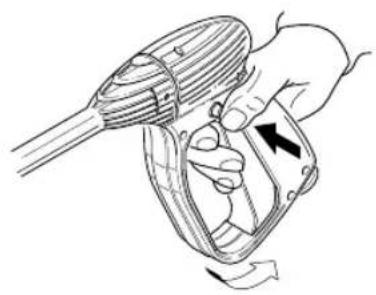
- Connect the lance to the pistol. To do this, insert the lance in the pistol and turn it clockwise as far as it will go.
Important!
Make sure the lance is securely attached to the pistol.
natural_image
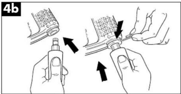
Illustration of hands using a tool to adjust a mechanical component (no text or symbols present)●Connect the pistol to the high-pressure hose.
text_image
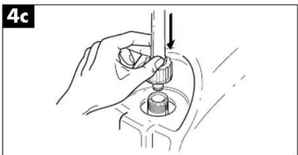
4b- Connect the high-pressure hose to the water outlet of the high-pressure cleaner.
natural_image
Hand holding a mechanical component with a downward arrow indicating motion (no text or symbols)GB
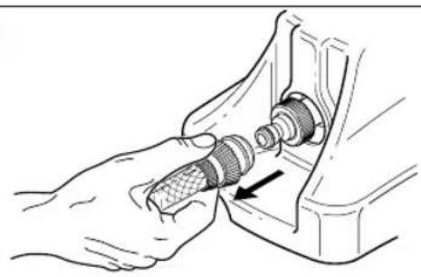
- Connect the water supply hose (not supplied) to the inlet of the high-pressure cleaner. The hose must measure at least 13 mm in diameter. The water supply must have sufficient pressure to deliver the quantity of water pumped by the high-pressure cleaner.
4d
natural_image
Illustration of a hand using a tool to adjust a mechanical component (no text or symbols visible)The temperature of the water jet is not to exceed 60^ C. The water pressure is not to exceed 10 bar.
Important:
The high-pressure cleaner should be operated with clean water. Unfiltered water or corrosive chemical agents will damage the high-pressure cleaner.
●The motor switch must be in the OFF position.
●The socket-outlet intended for the high-pressure cleaner must supply the voltage and frequency specified on the rating plate.
- If the motor stops during operation and does not start up again, wait 2 or 3 minutes before switching it on again.
5. Operation
- Open the water tap as far as it will go.
- Press the pistol trigger (Fig. 5a) and allow any air to escape.
5a
natural_image
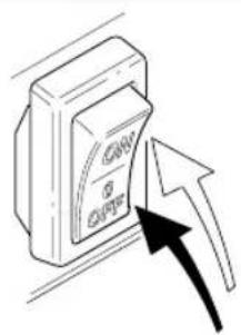
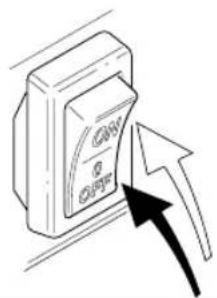
Illustration of a hand using a handheld device to lift a motor (no text or symbols present)●With the pistol open, switch on the motor by pressing the switch.
5b
text_image
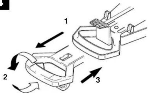
CAN OUTRAttaching the handle: Fig. 4
- Pull the handle completely out of its holder
- Turn the handle 180°.
- Re-insert the handle in the holder on the chassis.
4
text_image
Technical diagram showing three labeled mechanical components with directional arrows indicating motion or flow.GB
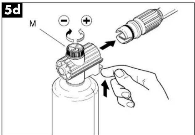
Using detergent
●Fill the tank of the foam spray lance with detergent (capacity approx. 0.5 l).
- Set the nozzle to „flat jet“ and attach the tank for foam cleaning.
text_image
5d M - + ↑●Distribute the detergent delivered and mixed with water.
Using the standard accessories
●The high-pressure cleaner is fitted with a nozzle head that allows you to regulate the jet from concentrated to flat jet.
natural_image
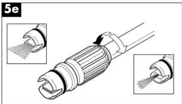
Technical illustration of a mechanical connector with two views showing internal structure and assembly (no text or symbols)●The nozzle head also has a foam distributor tank with a knob to regulate detergent intake.
Correct use of the rotating nozzle (only for models with a rotating nozzle)
To enhance washing performance, use the rotating nozzle supplied as follows:
●Switch off the high-pressure cleaner.
●Take off the regulating lance and attach the rotor nozzle to the pistol handle.
●Switch on the high-pressure cleaner again.
Cleaning recommendations
- First release the dirt by spraying the dry surfaces of the object to be cleaned with the flat jet. For vertical surfaces, always work from bottom to top.
Allow the detergent to take effect for 1-2 minutes, but make sure it does not dry. Then clean using the flat or high-pressure jet, starting at the bottom and always at a distance of at least 30 cm.
●Switch off the high-pressure cleaner.
●Turn off the water tap. - Release any residual pressure in the pistol until there is no water left in the adjustable nozzle head.
- Secure the pistol.
- Remove the plug from the socket-outlet.
●Before putting away the high-pressure cleaner for the winter, rinse it out with a mild, non-toxic antifreeze.
GB
6. Maintenance

Important!
Always disconnect from the mains before doing any maintenance or repair work.
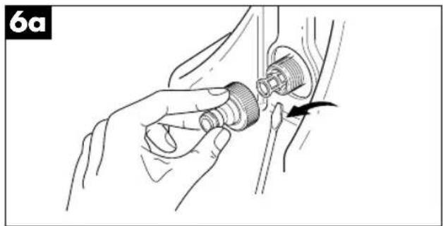
●To maintain the high-pressure cleaner in perfect working order, the intake filter must be checked and cleaned after every 50 hours of operation.
natural_image
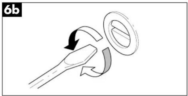
Illustration of a hand adjusting a mechanical component with a tool, no text or symbols present- If the machine has not been used for a long time, it may be furred up inside. Unblock the motor with a screwdriver inserted in the borehole at the rear.
natural_image
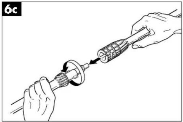
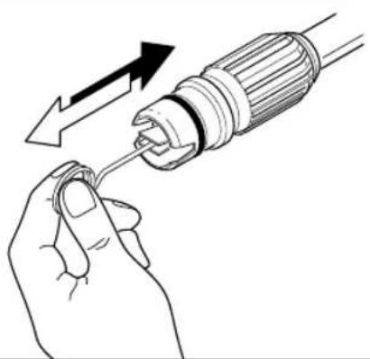
Diagram of a mechanical or electrical component with curved arrows indicating motion, no text or symbols present●Clean the nozzle head using the cleaner supplied. After dismantling the lance (Fig. 6c), remove any dirt from the borehole on the head (Fig. 6d) and rinse thoroughly.
natural_image
Illustration of hands using a tool to adjust a mechanical component (no text or symbols present)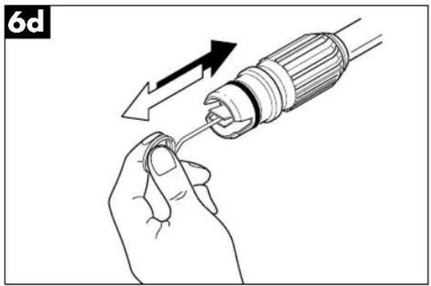
natural_image
Illustration of a hand holding a screwdriver with an arrow indicating the process (no text or symbols present)Then remove the key and proceed to start up the high-pressure cleaner.
7. Faults and their remedies
| Fault Cause Remedy | ||
| - Pump does not - Wrong or worn nozzle generate the prescribed - Intake filter is clogged - Clean filter pressure - Inadequate water supply - Open tap as far as it will go- Air is being drawn in - Check connections- Pump has not been rinsed out - Switch off high-pressure cleaner and actuate pistol until it produces an even water jet. Switch on again.- Adjustable head - Pull back the head inserted incorrectly | ||
| - Irregular operating pressure from an external tank | Water is being drawn in - Connect high-pressure cleaner to the water supply- Watertemperature too high - Lower temperature- Nozzle is clogged | - Use nozzle cleaner |
| - Very noisy | - Temperature is too high- Air is being drawn in - Check water inlet and outlet | - Lower temperature |
| - Water leaks from head/oil leak | - Worn seals | - Replace seals |
| - Motor does not start | - No voltage | - Check plug connection and voltage |
| - Motor hums but does not start | - Mains voltage is lower than that specified- Loss of voltage extension cable caused by the extension cable (cross section too small, cable too long)- High-pressure cleaner has not been used for a long time | - Check suitability of the power supply- Follow the instructions for extension cables- Unblock the motor inserted in the by with a screwdriver borehole at the rear (Fig. 6b) |
| - Mains cable is damaged | - Call customer service |
If the motor stops during operation and does not start up again, wait 2 or 3 minutes before switching it on again as the earth-leakage circuit-breaker will have been triggered. If this problem re-occurs, call customer service.

Attention!
i = Tuyau flexible haute pression
natural_image
Two black-and-white illustrations showing a person cleaning a street cleaner with a water spray and a cross symbol (no text or labels)natural_image
Illustration of hands using a tool to adjust a mechanical component (no text or symbols present)natural_image
Illustration of a hand using a tool to adjust a mechanical component (no text or symbols visible)F
natural_image
Illustration of hands using a tool to adjust a mechanical component (no text or symbols visible)text_image
Diagram showing three labeled mechanical components with directional arrows indicating motion or flow.5. Utilisation
natural_image
Illustration of a hand using a handheld device to interact with a mechanical component (no text or symbols visible)natural_image
Illustration of a device with an arrow pointing to it, no text or symbols presentF
Emploi du détergent
text_image
5d M - + ↑natural_image
Technical illustration of a cable connector with internal components and two close-up views (no text or symbols)natural_image
Illustration of a hand adjusting a mechanical component with a directional arrow (no text or symbols)natural_image
Illustration of hands using a mechanical tool to adjust a gear component (no text or symbols present)natural_image
Diagram of a mechanical or electrical component with curved arrows indicating motion (no text or symbols)6d
natural_image
Illustration of a hand holding a screwdriver with an arrow indicating the process (no text or symbols present)text_image
L1 S 4 5 r M 1~ a N 1 2 n T b c 230V/50Hz 220V/60Hz n = zwart b = wit a = blauw r = roodnatural_image
Illustration of hands using a tool to adjust a mechanical component (no text or symbols present)Let op!
natural_image
Hand holding a tool in a mechanical component, no visible text or symbolsNL
natural_image
Illustration of a hand connecting a mechanical component to a bracket, with an arrow indicating assembly direction (no text or symbols present)natural_image
Illustration of a hand holding a handheld device with a scroll wheel, showing motion direction (no text or symbols)natural_image
Technical illustration of a cable connector with two views showing internal structure and tip insertion (no text or symbols)natural_image
Illustration of a hand holding a threaded connector with a cable inserted, showing mechanical assembly (no text or symbols)natural_image
Diagram showing a tool interacting with a ring and curved arrows indicating motion (no text or symbols)natural_image
Illustration of hands using a tool to adjust a mechanical component (no text or symbols present)
natural_image
Illustration of a hand using a screwdriver to adjust or install a component (no text or symbols present)text_image
L1 S 4 5 r M 1~ a N 1 2 n T b c 230V/50Hz 220V/60Hz n = negro b = blanco a = azul r = rojonatural_image
Two black-and-white illustrations showing a person cleaning a water tap and another holding a cross symbol (no text or labels)Uso previsto
natural_image
Illustration of hands using a tool to adjust a mechanical component (no text or symbols present)natural_image
Hand holding a mechanical component with a downward arrow indicating motion (no text or symbols)E
natural_image
Illustration of hands connecting a mechanical component with a threaded connector (no text or symbols)natural_image
Illustration of a hand using a handheld device to interact with a mechanical device (no text or symbols visible)text_image
5d M - + ↑natural_image
Technical illustration of a mechanical connector with two views showing internal structure and assembly (no text or symbols)natural_image
Illustration of hands adjusting a mechanical component with a tool (no text or symbols visible)natural_image
Diagram of a mechanical component with curved arrows indicating motion or force direction (no text or symbols)natural_image
Illustration of hands using a tool to adjust a mechanical component (no text or symbols present)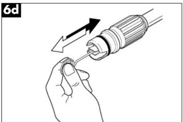
natural_image
Illustration of a hand holding a screwdriver with an arrow indicating the process (no text or symbols present)E
natural_image
Two black-and-white illustrations showing a person cleaning a street cleaning machine and another holding a cross symbol (no text or labels)Finalidade
natural_image
Illustration of hands using a tool to adjust a mechanical component (no text or symbols present)modo seguro à pistola.
natural_image
Illustration of a hand using a tool to press or install a mechanical component, no text or symbols presentP
natural_image
Illustration of hands connecting a mechanical component to a bracket (no text or symbols)text_image
Diagram showing three labeled parts of a mechanical component with directional arrows indicating motion or flow.5. Uso
natural_image
Illustration of a hand using a handheld device to interact with a mechanical component (no text or symbols visible)- Ao estar aberta a pistola, ligue o motor com o interruptor.
5b
natural_image
Illustration of a device with an arrow pointing to it, no text or symbols presenttext_image
5d M - + ↑natural_image
Technical illustration of a cable connector with two views showing internal structure (no text or symbols)natural_image
Illustration of a hand adjusting a mechanical component with a tool, no text or symbols presentnatural_image
Diagram of a mechanical or fluidic device with directional arrows indicating motion (no text or symbols)natural_image
Illustration of hands using a tool to adjust a mechanical component (no text or symbols present)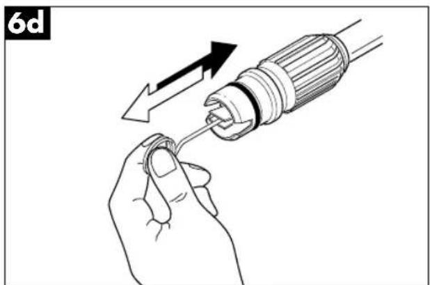
natural_image
Illustration of a hand holding a screwdriver with an arrow indicating the process (no text or symbols present)natural_image
Two black-and-white illustrations showing a person cleaning a water tap and another holding a cross symbol (no text or labels)Avsedd användning
natural_image
Illustration of hands using a tool to adjust a mechanical component (no text or symbols present)natural_image
Illustration of a hand using a tool to press or install a mechanical component, no text or symbols presentS
natural_image
Illustration of hands connecting a mechanical component with a bolt, showing a force or adjustment (no text or symbols present)natural_image
Illustration of a hand using a handheld tool to lift a mechanical component, no text or symbols presenttext_image
5d M - + ↑natural_image
Technical illustration of a mechanical connector with two views showing internal structure and assembly (no text or symbols)natural_image
Illustration of hands adjusting a mechanical component with a curved arrow indicating motion (no text or symbols)natural_image
Diagram showing a mechanical or fluidic component with curved arrows indicating motion, no text or symbols present.natural_image
Illustration of hands using a tool to adjust a mechanical component (no text or symbols present)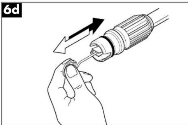
natural_image
Illustration of a hand holding a screwdriver with an arrow indicating the process (no text or symbols present)S
natural_image
Illustration of hands using a tool to adjust a mechanical component (no text or symbols present)natural_image
Hand holding a mechanical component with a downward arrow indicating force or direction (no text or symbols)FIN
natural_image
Illustration of hands connecting a mechanical component with a threaded rod (no text or symbols)natural_image
Illustration of a hand using a handheld device to interact with a mechanical component (no text or symbols visible)text_image
Diagram showing a device with labeled components and an arrow pointing to it, indicating a process or operation.text_image
5d M - + ↑natural_image
Technical illustration of a cable connector with two inserted parts, showing internal structure and assembly (no text or symbols)natural_image
Illustration of a hand holding a threaded connector with a cable, showing mechanical assembly (no text or symbols)natural_image
Diagram showing a mechanical or electrical component with curved arrows indicating motion, no text or symbols present.natural_image
Illustration of hands using a tool to adjust a mechanical component (no text or symbols present)
natural_image
Illustration of a hand holding a screwdriver with an arrow indicating the process (no text or symbols present)natural_image
Two black-and-white illustrations showing a person cleaning a street cleaner with a cross symbol (no text or symbols present)Brukens formål
natural_image
Illustration of hands using a tool to adjust a mechanical component (no text or symbols present)natural_image
Hand holding a mechanical component with a downward arrow indicating force or direction (no text or symbols)N
natural_image
Illustration of a hand using a tool to adjust a mechanical component (no text or symbols visible)natural_image
Illustration of a hand using a handheld device to lift a motor (no text or symbols present)natural_image
Illustration of a device with an arrow pointing to it, no text or symbols present
natural_image
Technical illustration of a fiber optic cable connector with two views showing internal structure and tip insertion (no text or symbols)natural_image
Illustration of a hand holding a connector with a cable, showing mechanical assembly (no text or symbols)natural_image
Illustration of hands using a tool to adjust a mechanical component (no text or symbols present)natural_image
Diagram of a mechanical component with curved arrows indicating motion or rotation (no text or symbols)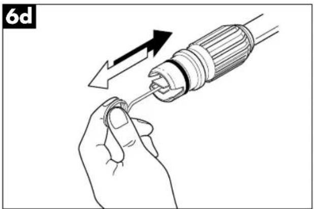
natural_image
Illustration of a hand using a screwdriver to adjust a screw (no text or symbols present)text_image
Technical diagram of a spray gun assembly with labeled parts including spray bottle, hoses, and control unitEik. 1
a=έξοδος νερού
natural_image
Two black-and-white illustrations showing a person cleaning a water tap and another holding a cross symbol (no text or labels)Προορισμός
natural_image
Illustration of hands using a tool to adjust a mechanical component (no text or symbols present)natural_image
Hand holding a tool with a mechanical component, no visible text or symbolsGR
natural_image
Illustration of a hand using a tool to adjust a mechanical component (no text or symbols visible)natural_image
Illustration of a hand using a handheld tool to interact with a device (no text or symbols visible)text_image
5d M - + ↑natural_image
Technical illustration of a mechanical connector with two views showing internal structure and assembly (no text or symbols)natural_image
Illustration of a hand adjusting a mechanical component with a tool, no text or symbols presentnatural_image
Illustration of hands using a tool to adjust a mechanical component (no text or symbols present)natural_image
Diagram of a mechanical component with curved arrows indicating motion or rotation (no text or symbols)
natural_image
Illustration of a hand holding a screwdriver with an arrow indicating the process (no text or symbols present)natural_image
Illustration of hands using a tool to adjust a mechanical component (no text or symbols present)natural_image
Hand holding a mechanical component with a downward arrow indicating motion (no text or symbols)I
natural_image
Illustration of a hand using a tool to adjust a mechanical component (no text or symbols present)natural_image
Illustration of a hand using a handheld device to lift a mechanical component, showing motion arrows (no text or symbols)natural_image
Technical illustration of a mechanical connector with two views showing internal structure and assembly (no text or symbols)natural_image
Illustration of hands adjusting a mechanical component with a tool (no text or symbols visible)natural_image
Illustration of hands using a tool to adjust a mechanical component (no text or symbols present)natural_image
Diagram of a mechanical or electrical component with curved arrows indicating motion, no text or symbols present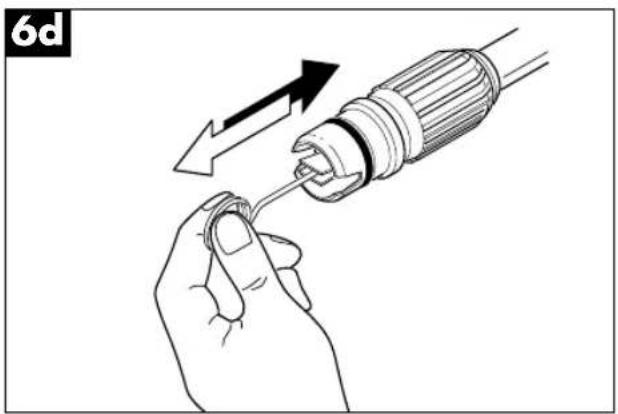
natural_image
Illustration of a hand holding a screwdriver with an arrow indicating the process (no text or symbols present)text_image
Technical diagram of a spray gun assembly with labeled parts including spray bottle, hose, and pressure gunFig. 1
a = Vandudløb
natural_image
Illustration of hands using a tool to adjust a mechanical component (no text or symbols present)natural_image
Illustration of a hand using a tool to press or install a mechanical component, no text or symbols presentDK
natural_image
Illustration of hands connecting a mechanical component with a threaded fitting (no text or symbols)natural_image
Illustration of a hand using a handheld tool to interact with a device (no text or symbols visible)text_image
5d M - + ↑natural_image
Technical illustration of a cable connector with two views showing internal structure and cable attachment (no text or symbols)natural_image
Illustration of a hand holding a mechanical component with a tool, no text or symbols presentnatural_image
Illustration of hands using a tool to adjust a mechanical component (no text or symbols present)natural_image
Diagram showing a mechanical or fluidic process with arrows indicating motion, no text or symbols present
natural_image
Illustration of a hand holding a screwdriver with an arrow indicating the process (no text or symbols present)text_image
Technical diagram of a mechanical device with numbered components for identificationtext_image
Exploded view diagram of an electric motor with numbered parts for identificationtext_image
Exploded view diagram of a mechanical assembly with numbered parts and exploded views for assembly details.⑤ EINHELL GARANTIBEVIS
The guarantee period begins on the sales date and is valid for 1 year.
Responsibility is assumed for faulty construction or material or functional defects.
Any necessary replacement parts an necessary repair work are free of charge.
We do not assume responsibility for consequential damage.
Your customer service partner
NL EINHELL-GARANTIE
DK EINHELL GARANTIBEVIS
Eschenstraße 6 · D-94405 Landau/Isar (Germany)
15 Warwick House Ind. Park, Banbury Road,
Sautham, Warwickshire CV 33 OPS
F Agence Commerciale Kettering
DK Danish Trading Co. Silkeborg ApS
Rodelundvej 11 - Rodelund
DK-8653 Them
Technical changes subject to change