HT 1600-F - Pressure washer EINHELL - Free user manual and instructions
Find the device manual for free HT 1600-F EINHELL in PDF.
| Product type | Pressure washer |
| Brand | Einhell |
| Model | HT 1600-F |
| Maximum pressure | 100 bar |
| Maximum water flow | 6.5 L/min |
| Motor power | 1.6 kW |
| Power supply | 230 V ~ 50 Hz |
| Protection type | IP 44 |
| Insulation class | F |
| Max. water temperature (inlet) | 60 °C (temporary) / 50 °C (continuous) |
| Max. supply water pressure | 10 bar |
| Fuse protection | 16 A |
| Motor rated speed | 2800 min⁻¹ |
| Oil capacity | 0.25 L |
| Oil type | 15W-40 |
| Weight | 14 kg |
| Sound level | 79 dB(A) |
| Spray functions | Round jet, flat jet, detergent spray |
| Safety devices | Gun lock, thermal protection, 30 mA RCD |
| Included accessories | Gun, lance, high-pressure hose, foam adapter, rotary nozzle |
| Periodic maintenance | Oil change every 300 h, filter cleaning, descaling |
| Warranty | 12 months |
Frequently Asked Questions - HT 1600-F EINHELL
User questions about HT 1600-F EINHELL
0 question about this device. Answer the ones you know or ask your own.
Ask a new question about this device
Download the instructions for your Pressure washer in PDF format for free! Find your manual HT 1600-F - EINHELL and take your electronic device back in hand. On this page are published all the documents necessary for the use of your device. HT 1600-F by EINHELL.
USER MANUAL HT 1600-F EINHELL
text_image
Technical diagram of a spray gun with labeled parts including hose, hose reel, and spray bottleInstallation

text_image
13 mm 2 3 4 8 1 OUTLET 4 INLET 5 6 7text_image
Technical diagram of a mechanical device with labeled parts including a spring, hose, and spray bottle
natural_image
Line drawing of a handheld electric shaver with a circular indicator labeled 'S' pointing to the handle (no text or symbols on the device itself)natural_image
Simple line drawing of a hand holding a plug with a lightning bolt inside, no text or symbols present.natural_image
Illustration of a hand holding a faucet with a valve, no text or symbols presentnatural_image
Hand holding a small electronic component, no text or symbols visiblenatural_image
Line drawing of a handheld tool emitting vapor, with no visible text or symbolstext_image
Diagram showing two-step instructions for using a tool, labeled ① and ②, with arrows indicating motion.Außerbetriebnahme
Wichtig!
natural_image
Three hand-drawn diagrams showing electrical connections: a switch, a plug, and a plug plug (no text or symbols)natural_image
Line drawing of a vacuum cleaner with directional arrows indicating motion (no text or symbols)| Maximum operating pressure in bar: 100 100 |
| Maximum volumetric flow in l/min: 6,5 7 |
| Mains voltage: 230 V - 50 Hz |
| Motor rating in kW: 1,6 |
| Type of protection: IP 44 |
| Insulation class: F |
| Maximum temperature of water supply in °C: 60 (temporary operation) |
| Maximum pressure of water supply in bar: 10 |
| Fusing in amps: 16 |
| Motor speed in rpm: 2800 |
| Motor protection: Thermal overload protection in winding |
| Oil filling in kg: 0.25 |
| Oil grade: 15 W-40 |
| Weight of unit: 14 kg |
| The power of recoil is less than 20 N. |
The workplace-related noise level is 79 dB(A).
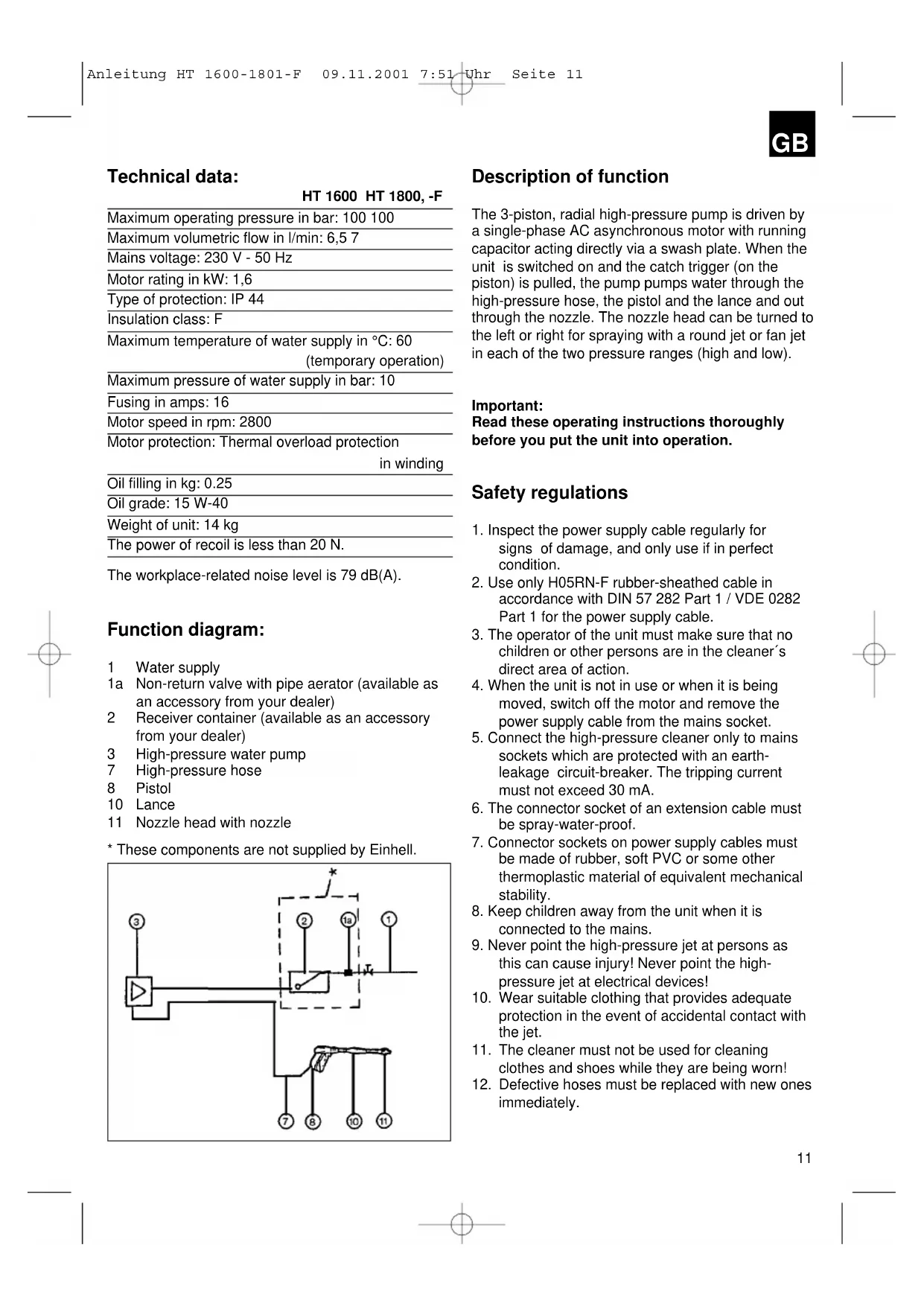
Function diagram:
1 Water supply
1a Non-return valve with pipe aerator (available as an accessory from your dealer)
2 Receiver container (available as an accessory from your dealer)
3 High-pressure water pump
7 High-pressure hose
8 Pistol
10 Lance
11 Nozzle head with nozzle
* These components are not supplied by Einhell.
flowchart
graph TD
    A["3"] --> B["Comparator"]
    B --> C["Switch"]
    C --> D["1a"]
    C --> E["1"]
    C --> F["7"]
    C --> G["8"]
    C --> H["10"]
    C --> I["11"]
    style C stroke-dasharray: 5 5
Description of function
The 3-piston, radial high-pressure pump is driven by a single-phase AC asynchronous motor with running capacitor acting directly via a swash plate. When the unit is switched on and the catch trigger (on the piston) is pulled, the pump pumps water through the high-pressure hose, the pistol and the lance and out through the nozzle. The nozzle head can be turned to the left or right for spraying with a round jet or fan jet in each of the two pressure ranges (high and low).
Important:
Read these operating instructions thoroughly before you put the unit into operation.
Safety regulations
- Inspect the power supply cable regularly for signs of damage, and only use if in perfect condition.
- Use only H05RN-F rubber-sheathed cable in accordance with DIN 57 282 Part 1 / VDE 0282 Part 1 for the power supply cable.
- The operator of the unit must make sure that no children or other persons are in the cleaner's direct area of action.
- When the unit is not in use or when it is being moved, switch off the motor and remove the power supply cable from the mains socket.
- Connect the high-pressure cleaner only to mains sockets which are protected with an earth-leakage circuit-breaker. The tripping current must not exceed 30 mA.
- The connector socket of an extension cable must be spray-water-proof.
- Connector sockets on power supply cables must be made of rubber, soft PVC or some other thermoplastic material of equivalent mechanical stability.
- Keep children away from the unit when it is connected to the mains.
- Never point the high-pressure jet at persons as this can cause injury! Never point the high-pressure jet at electrical devices!
- Wear suitable clothing that provides adequate protection in the event of accidental contact with the jet.
- The cleaner must not be used for cleaning clothes and shoes while they are being worn!
- Defective hoses must be replaced with new ones immediately.
GB
- Hold the pistol and lance with both hands during use.
- Do not set up the unit too close to where you want to clean.
- Automobiles, tractors, motorcycles, etc. must only be cleaned where an oil separator is installed at the sewer drain.
- Use only original spare parts from the manufacturer.
Instructions for the operator
Please observe the following additional points when using the high-pressure cleaner!
●Noise:
Wear officially approved ear muffs when working with the unit.
●Risk of injury:
Never point the water jet at persons or animals.
●Electric shock:
Be sure to pull out the mains plug before carrying out any maintenance work and before opening the casing. Never point the water jet at electrical equipment.
●Cleaning agents:
When working with cleaning agents, always follow the manufacturer's instructions.
●Inspection:
Have a qualified workshop inspect the unit according to how heavily it is used but at least once every year. Replace any faulty parts such as the power cable and hose with original spare parts.
Power connection
You are to connect the cleaner only to a properly installed mains socket with earthing contact. If in doubt, consult an electrician.
Compare the data on the unit's rating plate with the data of your own mains supply to make sure that the cleaner can be operated from your mains, and install a 16 A mains fuse if not already available. Only now are you allowed to insert the plug in the mains socket.
To switch on the high-pressure cleaner, simply press the rocker switch at the rear.
The cleaner is protected against overloading.
If overloading occurs, the electric current is switched off automatically to prevent the motor winding from burning out. For safety reasons, you are required to wait approximately 5 minutes before you can switch on the cleaner again after the automatic cut-out has responded. Rectify the cause of the overloading first. To be able to switch the unit back on again you must always turn off the switch first. After the mandatory waiting period has elapsed, you can then put the unit back into operation by pressing the rocker switch. When using extension cables, please remember to protect the connecting socket from moisture.
Damaged cables
It often happens that the insulation on the power supply cable becomes damaged.
Common causes are:
●Running over the cable with heavy equipment
●Pinching the cable in doors or windows
●Cracking due to ageing
●Kinking due to improper fastening or routing of the cable
Cables with damaged insulation must never be used because they are extremely dangerous!
Cables, plugs and portable socket outlets must comply with the following conditions:
Power supply cables for high-pressure cleaners must be rubber-insulated.
The type designation must be printed on the cable. Purchase only cables with printed identification marks!
Plugs and portable outlets must be made of rubber.
The cables should be kept as short as possible.
Longer cables require conductors with larger cross-sections.
See the table „Extension cable data“ for length specifications.
Power supply cables must be inspected regularly. Always remove the plug from the mains socket before inspecting cables. Unroll cables completely from cable drums. Check the cables where they enter plugs and portable outlets to ensure that they are not kinked.
GB
Take the safety precaution of using highly sensitive residual-current devices with nominal currents of 10 or 30 milliamperes. In the event of an accident these devices switch off before the current becomes dangerous.
A qualified electrician can install a residual-current device in your building's electrical system as a permanent fixture.
Alternatively your electrical dealer can supply you with a plug-in residual-current device for inserting between the wall socket and the power cable.
Devices of this type are produced by various manufacturers. When working outdoors, remember to use only devices which are protected from rain and moisture. These devices bear the symbol

or are marked with the protection code „IP 44“.
Table: Extension cable data
| Voltage | Cable | Cross-section |
| V length mm | ^2 | |
| 230 up to 20 m 1.5 | ||
| 230 20 to 50 m 2.5 | ||
Steps before putting the unit into operation
Note the regulations of your local water supply authority.
Water connection
Screw the water supply hose to the cleaner's water inlet connection (we recommend using a reinforced hose with an internal diameter of at least 12-13 mm = 1/2").
Screw the high-pressure hose to the cleaner's water outlet connection. Make sure that all the connections are tightened securely and that no air can enter.
Important!
●Never operate the cleaner without water. Make sure that there is always a continuous, sufficient water supply (at least 11-12 l/min). Operating the cleaner without water will cause severe damage to the seals.
●The supply water must be free of dirt, sand and other contaminants. If necessary, install a filter in the water inlet.
●The supply water must contain no aggressive cleaning agents or solvents.
●The maximum water supply temperature must not exceed 60^ C (intermittent operation).
Areas of application
●For cleaning transport equipment, agricultural vehicles and rooms.
●All types of cleaning jobs in the food industry, livestock farms, dairies and abattoirs.
●For cleaning drainage pipes, floors, walls, bathing and sanitary facilities, glass exteriors.
●For blasting with abrasives.
Electrical connection
You are to connect the cleaner only to a properly installed mains socket with earthing contact. If in doubt, consult an electrician.
Compare the data on the unit's rating plate with the data of your own mains supply to make sure that the cleaner can be operated from your mains, and install a 16 A mains fuse if not already available. Only now are you allowed to insert the plug in the mains socket.
GB
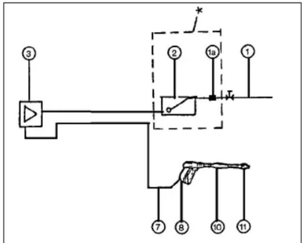
Assembly drawing
- On/Off switch
- Connection cable with power plug
- Water outlet
- Water inlet + filter
- Pistol
- High-pressure hose
- Lance
- Foam spray attachment
text_image
Technical diagram of a hair dryer with labeled parts including hose, hose reel, and spray bottleInstallation

text_image
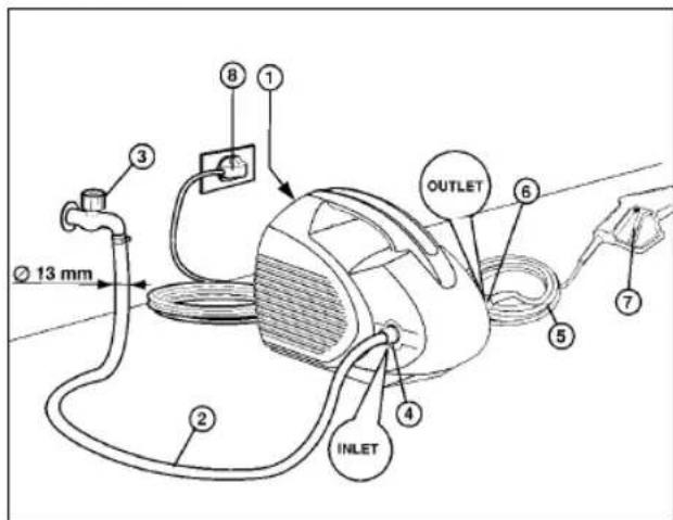
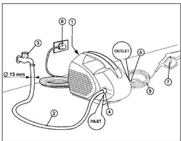
Ø 13 mm ① ② ③ ④ ⑤ ⑥ ⑦ ⑧ INLET OUTLET- The main switch has to be in „O“ position (item 1).
- The water supply hose (item 2) has to be connected to INLET (item 4). Use a hose designed for a minimum capacity of 15 bar with an inner diameter of at least 12-13 mm (1/2").
- Fit the lance to the pistol.
- Connect the high-pressure hose (item 5) to the OUTLET (item 6) and to the pistol. The water temperature should never exceed 50^ in continuous operation.
- Open the water tap (item 3).
- Press the pistol trigger (item 7) until water emerges from the lance nozzle and flushes out any residues left in the line.
- Insert the power plug in the socket-outlet (item 8).
- Switch on the machine by moving the switch to "I" position. Starting is easier and the machine is placed under less strain if you press the pistol trigger before switching on.
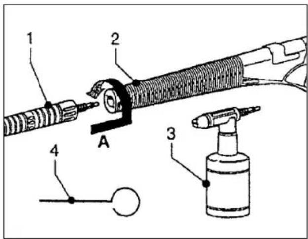
Fitting the lance
The lance (item 1) is latched onto the spray pistol (item 2) with the bayonet connector. Insert the lance in the direction indicated by the arrow „A“ and turn approx. 15° clockwise until the two parts are fully connected. The nozzle cleaning needle (item 4) can be used to remove any dirt which may collect in the nozzle. Caution! Before cleaning, switch off the machine and disconnect from the water supply.
text_image
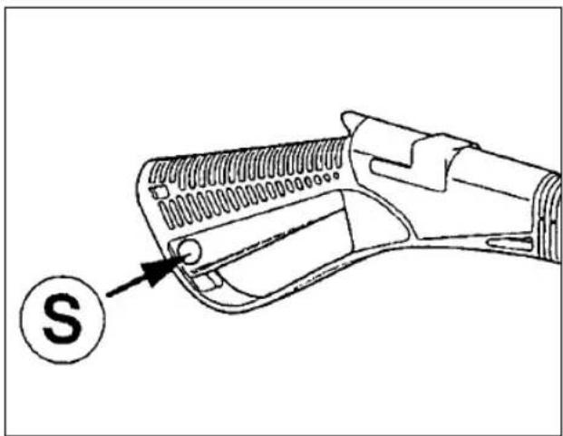
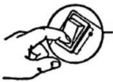
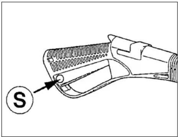
Technical diagram of a mechanical device with labeled parts including a threaded rod, wash bottle, and cable connection.Pistol safety lock
Always actuate the safety lock (S) on the pistol whenever the machine is not being used. This will prevent the machine starting up accidentally.
natural_image
Line drawing of a handheld electric shaver with a circular indicator labeled 'S' pointing to the handle (no text or symbols on the device itself)Starting up and notes on operation
- Plug the unit into the mains (see the sections "Safety regulations" and "Electrical connection").

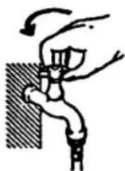
- Open the water tap (see the sections „Steps before putting the unit into operation“ and „Water connection“).
natural_image
Illustration of a hand climbing a wall with an arrow indicating motion (no text or symbols)- Bleed the system of air by pulling the pistol trigger.
- Switch on the cleaner with the pistol open (move the power switch on the cleaner to position 1).
natural_image
Hand holding a small object inside a circular frame (no text or symbols visible)To purge any particles which may have accumulated inside the cleaner system, we recommend spraying for 1-20 seconds with the spray pistol only. Such particles could block the high-pressure nozzle and jeopardize its proper operation. Never clean the high-pressure nozzle with sharp metallic objects. Use only blasts of compressed air.
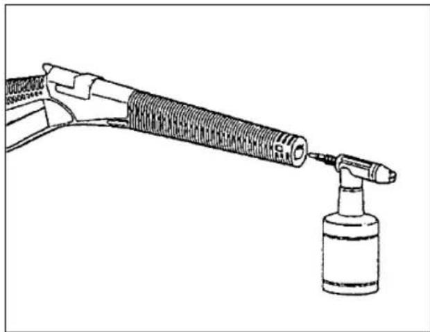
Spraying with cleaning agents
Remove the front section of the lance and fit the foam-spray attachment in its place. Then fill the container with a suitable cleaning agent and screw it into the nozzle holder. When you pull the pistol trigger, the cleaning agent is drawn automatically from the container and sprayed with the water.
If the cleaning agent is not longer needed, you must remove the attachment and refit the normal lance section.
Instructions for the proper use of cleaning agents
- Make up cleaning agents in their correct ratio of concentration (follow the manufacturer's instructions).
●Distribute the cleaning solution evenly over the surface to be cleaned with the high-pressure cleaner and allow the solution a few minutes to work (be careful when working on hot surfaces, e.g. engines or objects exposed to bright sunshine).
●Finally, rinse down the treated surface uniformly with water from the high-pressure cleaner.
It is not advisable to use intensively foaming or acidic cleaning agents. Use only standard brand-name products.
GB
Important: For safety reasons, always switch off the motor before changing the nozzle!
natural_image
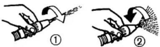
Line drawing of a hairdryer with a syringe, no text or symbols presentChanging over from round-jet to fan spraying You can spray with either a round jet or fan jet as required.
To adjust, simply turn the nozzle head to the right (1) for a round jet or to the left (2) for a fan jet (see picture).
text_image
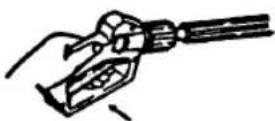
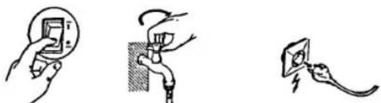
Diagram showing two-step instructions for using a tool, labeled ① and ②, with arrows indicating direction.Shutting down
Important!
Whenever you stop working and switch off the pump, always depressurize the system by opening the pistol.
Switch off the unit Close the water tap Pull the plug out of the socket
natural_image
Three hand-drawn diagrams showing electrical connections: a pencil, a switch, and a plug (no text or symbols)Shutting down for longer periods
If you do not intend to use the high-pressure cleaner for a longer period of time, we recommend rinsing the system thoroughly with an ample amount of water. Use clean water without cleaning agents.
Antifreeze precautions
When the unit is stored away, it must be protected from freezing up. If you have to use a storage room that is very cold or exposed to frost, it is advisable to fill the unit first with an antifreeze agent. The unit can draw in the antifreeze most easily if the container is held at a higher level.
Monitoring and maintenance
Important!
Before beginning repair or maintenance work, always remove the plug from the mains socket. Repairing the cleaner while it is still connected to the mains current supply is extremely dangerous and can be fatal!
The machine requires no maintenance. It is delivered with enough oil for it to be used for around 300 hours. You must then arrange for a service workshop to change the oil.
Water supply
If the water supply line is excessively dirty, install a filter in the water inlet.
Hoses
The high-pressure cleaner is equipped at the factory with hoses designed for its operating pressures. If these hoses need replacement, only ever use the manufacturer's original hoses or types of identical quality bearing the necessary markings.
Important!
Never draw solvents such as paint thinners, gasoline, oil, etc. or unfiltered water into the cleaner. The seals in the system are not solvent-proof. Solvent mist is highly flammable, explosive and poisonous!

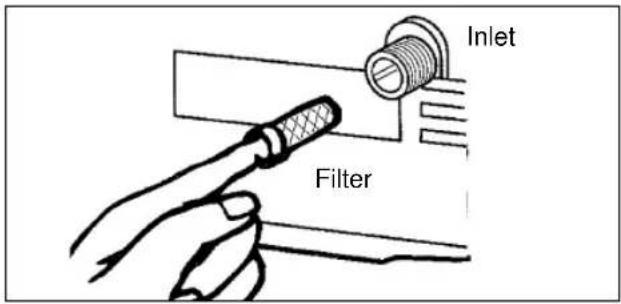
Checking the water intake filter
Check the intake filter at set intervals in order to avoid clogging. Failure to do so may jeopardize the proper operation of the pump (see the figure).
text_image
Inlet FilterDecalcifying
You must decalcify the high-pressure cleaner at regular intervals. Just how frequently this is necessary will depend on the hardness of the water in your area.
Pour the decalcifier into a container with a capacity of at least 30 litres and mix with water in a ratio of 1 litre of decalcifier to 15 litres of water.
Use the high-pressure cleaner with a hose to draw up the mixture. Submerge the pistol immediately in the container to create a closed-circuit and allow the decalcifying solution to circulate for at least 10 minutes (leave the unit switched on).
You will find it easier to start up the circulation if you place the container above the pump.
Important!
Decalcifier is caustic! Observe the manufacturer's safety precautions printed on the packaging!
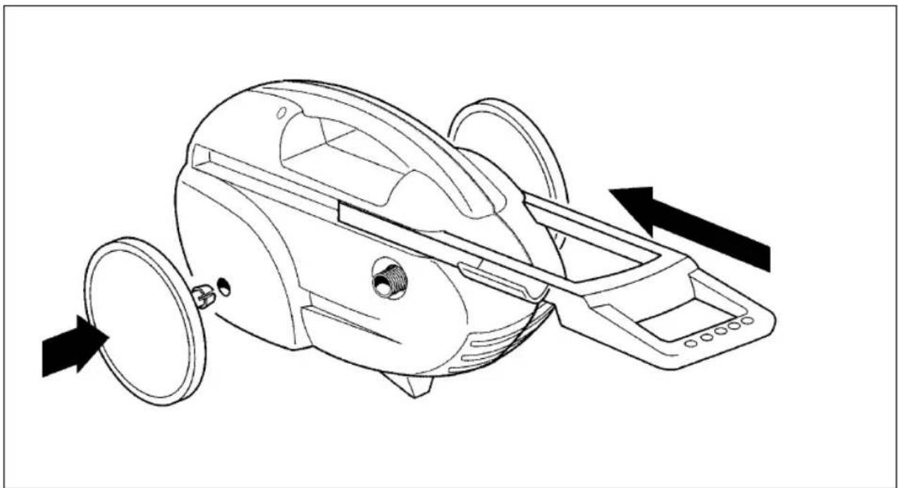
Fitting the wheels and stand
You can make your high-pressure cleaner mobile by fitting the supplied wheels and stand. The wheels are simply inserted in the prepared holes on the sides and the stand is plugged in place on the bottom of the housing (see drawing).
Insert the steering handle in the guide slot on the housing. The handle latches home in bottom and top position. To release the catch, press in the two lugs.
You can then move the handle in or out as required.
natural_image
Line drawing of a mechanical device with directional arrows indicating motion or assembly (no text or symbols)GB
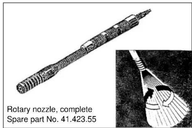
Working with the rotary nozzle
The rotary nozzle comes fitted in position ready for immediate use.
Rotation of the cleaning jet as it emerges from the rotary nozzle lends it twice the cleaning power of a normal cleaning nozzle.
The first time a new nozzle is used it may be rather slow in starting until the nozzle works itself free. If the nozzle fails to rotate immediately, press the pistol trigger a few times briefly in quick succession.
The rotary nozzle was developed specially for cleaning path slabs, facade walls, swimming-pools and other surfaces on which dirt or moss accumulates.
Caution! Risk of injury! Never point the water jet at persons or animals. For safety reasons, always switch off the motor before changing the nozzle!
text_image
Rotary nozzle, complete Spare part No. 41.423.55A bayonet lock is used to fasten the lance, rotary nozzle and other accessories to the pistol handle. To fasten, insert the lance in the pistol body, press and twist to the left up to the stop. To unfasten, press the lance into the pistol again, twist to the right and pull out.
Disposing of the machine
When the high-pressure cleaner is no longer required, proceed as follows:
- Remove the power plug and render the machine unworkable.
●Store in a place that is inaccessible to children.
●Parts from the old machine are not to be used as replacement parts.
●Disassemble the machine and dispose of its various parts in accordance with the regulations in force in your country.
Troubleshooting
| Problem Cause Remedy | ||
| Pump lacks pressure - Unsuitable | or worn nozzle - Replace nozzle- System is drawing in air - Check intake pipes and seal- Worn or dirty valves - Replace or clean valves | |
| Pressure gauge indicates - Worn fluctuations - Water temperature | or dirty valves - Replace or clean valvestoo high - Reduce intake temperature- Worn seals - Replace seals- Worn nozzle - Replace nozzle | |
| Noise - Water temperature too high | - Reduce water temperature- System is drawing in air - Check pipes- Dirty or worn valve - Clean or replace valve | |
| Loss of water at head - Worn sealing rings | - Replace sealing rings | |
| Loss of oil - Worn oil sealing rings | - Replace sealing rings | |
| Motor fails to start | - No electricity | - Check whether the plug is properly inserted in the socket and whether the cable is live- Check whether the switch is working |
| Motor whines but does not start up | - Incorrect mains voltage (less than the prescribed minimum)- The voltage has been reduced by an extension cable that has the wrong cross-section or is too long | - Check power supply for suitability- Follow the instructions for the use of extension cables |
F
Données techniques:
HT 1600 HT 1800,-F
text_image
Technical diagram of a hair dryer with labeled parts including hose, hose reel, and spray bottleInstallation

text_image
13 mm 2 3 4 8 1 OUTLET 4 INLET 5 6 7text_image
Technical diagram of a mechanical device with labeled parts including a tool, spring, and spray bottle
natural_image
Line drawing of a handheld electric gun with a labeled 'S' and an arrow pointing to the handle (no text or symbols beyond the label)natural_image
Simple line drawing of a hand holding a valve or pipe against a wall, with no text or symbols present.natural_image
Hand holding a small electronic component, no text or symbols visiblenatural_image
Line drawing of a hairdryer with a hose and spray bottle (no text or symbols)text_image
Diagram showing two-step instructions for using a tool, labeled ① and ②, with arrows indicating direction.Mise hors service
Important!
natural_image
Three hand-drawn diagrams showing electrical connections: a plug, a switch, and a plug with a fuse (no text or symbols)natural_image
Line drawing of a vacuum cleaner with directional arrows indicating motion (no text or symbols)F
text_image
Technical diagram of a hair dryer with labeled parts including hose, hose reel, and spray bottleInstallatie

text_image
13 mm 2 3 4 8 1 OUTLET 6 5 7 INLETtext_image
Technical diagram of a mechanical assembly with labeled parts including a threaded rod, spray bottle, and numbered components.natural_image
Line drawing of a firearm with a labeled arrow pointing to the handle (no text or symbols present)natural_image
Simple line drawing of a hand holding a device with a curved arrow indicating motion (no text or symbols)natural_image
Hand holding a small electronic component, no text or symbols visiblenatural_image
Line drawing of a hairdryer tool with a spray bottle attached (no text or symbols)text_image
Diagram showing two-step instructions for using a tool, labeled ① and ②, with arrows indicating direction.natural_image
Three hand-drawn electrical circuit diagrams showing different installation or installation states (no text or symbols)natural_image
Line drawing of a vacuum cleaner with directional arrows indicating motion (no text or symbols)
text_image
Technical diagram of a hair dryer with labeled parts including hose, hose reel, and spray bottleInstalación

text_image
13 mm 2 3 4 8 1 OUTLET 4 INLET 5 6 7text_image
Technical diagram of a mechanical device with labeled parts including a tool, spring, and spray bottleE
natural_image
Line drawing of a firearm with a labeled arrow pointing to the handle (no text or symbols present)natural_image
Simple line drawing of a hand holding a plug with a lightning bolt inside, no text or symbols present.natural_image
Simple line drawing of a hand climbing a wall with an arrow indicating motion (no text or symbols)natural_image
Hand holding a small object inside a circular frame (no text or symbols visible)natural_image
Line drawing of a handheld tool emitting vapor, with a smaller bottle nearby (no text or symbols)Pase de chorro redondo a chorro plano
text_image
Diagram showing two-step instructions for using a tool, labeled ① and ②, with arrows indicating action.natural_image
Three-step electrical circuit diagram showing hand holding a socket, switch, and plug (no text or symbols)natural_image
Line drawing of a vacuum cleaner with mechanical components and directional arrows indicating motion (no text or symbols)E
text_image
Technical diagram of a hair dryer with labeled parts including hose, hose reel, and spray bottleInstalação
text_image
Ø 13 mm ① ② ③ ④ ⑤ ⑥ OUTLET ⑦ INLETtext_image
Technical diagram of a mechanical device with labeled parts including a tool, spring, and spray bottlenatural_image
Line drawing of a handheld electric shaver with a circular indicator labeled 'S' pointing to the handle (no text or symbols on the device itself)natural_image
Simple line drawing of a hand holding a plug into a socket with a lightning bolt (no text or symbols)natural_image
Simple line drawing of a person climbing a wall with an arrow indicating motion (no text or symbols)natural_image
Line drawing of a hairdryer with a bottle, no text or symbols presenttext_image
Diagram showing two-step instructions for using a tool, labeled ① and ②, with arrows indicating direction.natural_image
Three hand-drawn diagrams showing electrical connections: holding a switch, adjusting a component, and connecting wires (no text or symbols)natural_image
Line drawing of a vacuum cleaner with directional arrows indicating motion (no text or symbols)
text_image
Technical diagram of a spray gun with labeled parts including hose, hose reel, and spray bottletext_image
Technical diagram of a mechanical device with labeled parts including a tool, spring, and spray bottle
natural_image
Line drawing of a handheld device with a circular indicator labeled 'S' pointing to a button (no text or symbols on the device itself)natural_image
Illustration of a person climbing a wall with an arrow indicating motion (no text or symbols)natural_image
Hand holding a small electronic component, enclosed in a circular frame (no text or symbols visible)natural_image
Line drawing of a handheld tool emitting vapor, with no visible text or symbolstext_image
Diagram showing two-step instructions for using a tool, labeled ① and ②, with arrows indicating direction.Avslutning
Viktigt!
natural_image
Three-step diagram showing hand installation, valve insertion, and plug installation (no text or symbols)natural_image
Line drawing of a vacuum cleaner with directional arrows indicating motion (no text or symbols)S
text_image
Technical diagram of a spray gun with labeled parts including hose, hose reel, and spray bottletext_image
Ø 13 mm ① ② ③ ④ ⑤ ⑥ ⑦ ⑧ INLET OUTLET
text_image
Technical diagram of a mechanical device with labeled parts including a spring, hose, and spray bottlenatural_image
Line drawing of a handheld device with a labeled 'S' and an arrow pointing to its grip (no text or symbols beyond the label)natural_image
Illustration of a hand climbing a wall with an arrow indicating motion (no text or symbols)natural_image
Line drawing of a handheld tool emitting vapor onto a cylindrical device (no text or symbols)text_image
Diagram showing two-step instructions for using a tool, labeled ① and ②, with arrows indicating motion or movement.natural_image
Three hand-drawn diagrams showing electrical connections: a plug, a switch, and a plug with a wire (no text or symbols)Vedenimusuodattimen tarkastus
natural_image
Line drawing of a vacuum cleaner with directional arrows indicating motion (no text or symbols)
text_image
Technical diagram of a hair dryer with labeled parts including hose, hose reel, and spray bottletext_image
Ø 13 mm ① ② ③ ④ ⑤ ⑥ ⑦ ⑧ INLET OUTLET
text_image
Technical diagram of a mechanical device with labeled parts including a spring, hose, and spray bottleGR
natural_image
Line drawing of a firearm with a labeled arrow pointing to the handle (no text or symbols present)natural_image
Simple line drawing of a person climbing a wall with an arrow indicating motion (no text or symbols)- Kávete
natural_image
Hand holding a small electronic component, enclosed in a circular frame (no text or symbols visible)natural_image
Line drawing of a hairdryer with a bottle being dispensed from it (no text or symbols)text_image
Diagram showing two-step instructions for using a tool, labeled ① and ②, with arrows indicating direction.Σημαντικό!
natural_image
Three-step electrical circuit diagram showing hand holding a socket, switch, and plug (no text or symbols)natural_image
Line drawing of a vacuum cleaner with mechanical components and directional arrows indicating motion (no text or symbols)text_image
Technical diagram of a hair dryer with labeled parts including hose, hose reel, and spray bottleInstallation
text_image
13 mm 2 3 4 5 6 7 8 INLET OUTLETtext_image
Technical diagram of a mechanical assembly with labeled parts including a threaded rod, spray bottle, and cablePistolens sikkerhedsanordning
natural_image
Line drawing of a handheld device with a circular indicator labeled 'S' pointing to a button (no text or symbols on the device itself)natural_image
Illustration of a hand performing a vertical maneuver with a curved arrow indicating motion (no text or symbols)natural_image
Hand holding a small electronic component, no text or symbols visiblenatural_image
Line drawing of a hairdryer with a syringe, no text or symbols presenttext_image
Diagram showing two-step instructions for using a tool, labeled ① and ②, with arrows indicating direction.natural_image
Three hand-drawn diagrams showing electrical connections: a pencil, a switch, and a plug (no text or symbols)stråle.
Ud-af-drift-tagning
Vigtigt!
natural_image
Line drawing of a vacuum cleaner with directional arrows indicating motion (no text or symbols)
text_image
Technical diagram of a mechanical assembly with numbered parts, likely an engine or pump component.text_image
Exploded view diagram of a mechanical device with numbered parts for identificationtext_image
Labeled diagram of a firearm with numbered parts for identificationtext_image
Labeled diagram of a spray gun assembly with numbered parts for identificationtext_image
Technical diagram of a mechanical assembly with numbered parts for identificationtext_image
① L 1 2 N 4 5 ② ③ WORKING WINDING START WINDING MOT. 1 ~ ④ ⑤ ⑥ 3 x 1D
① = Schalter
② = rot
③ = rot
④ = schwarz
⑤ = grün
⑥ = gelb/grün
GB
① = switch
② = red
③ = red
④ = black
⑤ = green
⑥ = yellow/green
F
① = Interrupteur
② = Rouge
③ = Rouge
④ = Noir
⑤ = Vert
⑥ = Jaune/vert
E
① = interruptor
② = rojo
③ = rojo
④ = negro
⑤ = verde
⑥ =amarillo/verde
S
① = Brytare
② = röd
③ = röd
④ = svart
⑤ = grön
⑥ = gul-grön
The guarantee period begins on the sales date and is valid for 1 year.
Responsibility is assumed for faulty construction or material or functional defects.
Any necessary replacement parts an necessary repair work are free of charge.
We do not assume responsibility for consequential damage.
Your customer service partner
F GARANTIE EINHELL
⑤ EINHELL GARANTIBEVIS
DK EINHELL GARANTIBEVIS
Eschenstraße 6 · D-94405 Landau/Isar (Germany)
Ersatzteil-Abt.: Telefon (0 99 51) 942 356 • Telefax (0 99 51) 52 50 Reparatur-Abt.: Telefon (0 99 51) 942 357 • Telefax (0 99 51) 26 10
Technical changes subject to change