
Villa 15 HST - Lawn mower STIGA - Free user manual and instructions
Find the device manual for free Villa 15 HST STIGA in PDF.

| Product type | Ride-on lawn mower |
| Brand | STIGA |
| Model | Villa 15 HST |
| Transmission | Hydrostatic |
| Engine | 4-stroke, petrol |
| Fuel | Unleaded petrol |
| Cutting height | Electric adjustment |
| Cutting system | Front cutting deck |
| Steering | Rear wheel steering |
| Parking brake | Yes, with locking lever |
| Battery | 12 V |
| Spark plug | Champion XC12YC or equivalent |
| Engine oil (class) | SJ or higher |
| Air filter | Paper (B&S model) or paper + pre-filter (STIGA model) |
| Fuse | 20 A |
| Tyre pressure | See technical table |
| Compatible accessories | Trailer, leaf collector, fertiliser spreader, front sweeper, snow plow |
| Safety | Micro-switches, engine stops if driver leaves seat |
| Intended use | Lawn mowing, non-professional use |
| Maximum slope | 10° (17%) |
Frequently Asked Questions - Villa 15 HST STIGA
User questions about Villa 15 HST STIGA
0 question about this device. Answer the ones you know or ask your own.
Ask a new question about this device
Download the instructions for your Lawn mower in PDF format for free! Find your manual Villa 15 HST - STIGA and take your electronic device back in hand. On this page are published all the documents necessary for the use of your device. Villa 15 HST by STIGA.
USER MANUAL Villa 15 HST STIGA
natural_image
Yellow and gray electric mobility scooter with black seat and wheels (no visible text or symbols)Villa series 2WD
Villa Spring
Villa 15 HST
Type V 301
TOSAERBA CON CONDUCENTE A BORDO SEDUTO
SEKAČKA SE SEDÍCÍ OBSLUHOU
HAVETRAKTOR/HAVETRAKTOR MED FRONTKLIPPER (FM)
AUFSITZMÄHER (RASENMÄHER MIT FAHRERSITZ MIT SITZENDEM BENUTZER)
RIDE-ON LAWNMOWER WITH SEATED OPERATOR
CORTADORA DE PASTO CON CONDUCTOR SENTADO
ISTUVA JUHIGA MURUNIITJA
PÄÄLTÄAJETTAVA RUOHONLEIKKURI
![12 [Gear] B A C D](/content/2026/03/518154/images/9fc7d5f7f396485b639e0f31cdb06d890167f34c21b61e78d42fa8200148566d.jpg)
![13 [Hydrostatic] H D B C G A E F](/content/2026/03/518154/images/401b531c317bf775c1af8efdfd5db7a1301e8e0b6ce2ced2053302d4d7368490.jpg)
![14 [Hydrostatic] A](/content/2026/03/518154/images/2f216099942b764575ed0b7851345b7e12b1ef721772d055698006e109924a78.jpg)
natural_image
Mechanical assembly diagram showing a wheel and gear assembly with directional arrow (no text or symbols)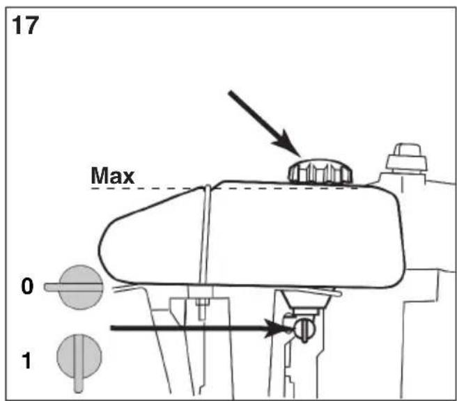
![18 [STIGA] E D C B A](/content/2026/03/518154/images/4fbb2370cc780d8b07174ee8830828432cd57fc726f47161a40df58875f9c640.jpg)
![19 [B&S] C B D A ADD-FULL](/content/2026/03/518154/images/048f970ec4738f37e1d213364fa72958bde5895cec9d75b7280fcb1f7d7cf2ef.jpg)
0 TABELLA DATI TECNICI
| [1] | Type | |
| [2] | Model | |
| [3] | Engine | |
| [4] | Engine displacement | |
| [5] | Traction | |
| [6] | Transmission | |
| [A] | mechanical | |
| [B] | hydrostatic | |
| [7] | Power | |
| [8] | Engine revs | |
| [9] | Electrical System | |
| [10] | Battery | |
| [11] | Fuel | |
| [A] | Unleaded petrol | |
| [12] | Engine oil | |
| [13] | Engine oil, service category | |
| [A] | SJ or higher | |
| [14] | Engine oil tank capacity | |
| [15] | Spark plug | |
| [A] | Champion XC12YC or equivalent | |
| [16] | Spark gap | |
| [17] | Tyres, front | |
| [18] | Tyres, rear | |
| [19] | Tyre pressure | front |
| rear | ||
| [20] | Cutting height | |
| [A] | For the cutting height, please refer to the "Technical Data Table" in the cutting device assy manual. | |
| [21] | Forward travel speed (indicative) | |
| [22] | Reverse travel speed (indicative) | |
| [23] | Weight | |
| [24] | Overall dimensions | |
| [25] | A = Length | |
| [26] | B = Pitch | |
| [27] | C = Height | |
| [28] | D = Width | |
| [29] | Measured sound power level | |
| [30] | Uncertainty | |
| [31] | Guaranteed sound power level | |
| [32] | Sound pressure level | |
| [33] | Uncertainty | |
| [34] | Vibration value in the driver's seat | |
| [35] | Uncertainty | |
| [36] | Vibration value in the steering wheel | |
| [37] | Uncertainty | |
| [38] | Cutting height electric adjustment | |
| [39] | ACCESSORIES AVAILABLE ON REQUEST | |
| [40] | Description | |
| [41] | Trailer |
| [42] | Grass and leaf collector |
| [43] | Fertilizer spreader |
| [44] | Cutting device assy |
| [45] | Front sweeper |
| [46] | Blade type snow plough |
| [47] | TABLE FOR CORRECT ACCESSORY COMBINATIONS |
| [48] | REAR ACCESSORIES |
| [49] | FRONT ACCESSORIES |
| [50] | Accessory |
For this maintenance operation is recommended to contact an authorised assistance centre.
1.1 ROZVRŽENÍ MANUÁLU 4
1.2 SYMBOLY 4
1.3 PŘECHOVÁVANÍ MANUÁLU. 4
2 SEZNÁMENÍ SE SE STROJEM. 4
2.1 MODELY [Gear]. 4
2.2 MODELY [Hydrostatic] 4
2.3 PŘEDPOKLÁDANÉ POUŽITÍ. 5
2.3.1 Definování typu uživatele. . . . . . . . . . . . . . . . . . . . . . . . . . . . . . . . . . . . . . . . . . . . . . . . . . . . . . . . . . . 5
2.4 NEVHODNÉ POUŽITÍ 5
2.5 BEZPEČNOSTNÍ NÁVĚSTÍ 5
2.5.1 Nálepky (4). 5
2.6 IDENTIFIKAČNÍ ŠTÍTEK VÝROBKU. 6
2.7 HLAVNÍ KOMPONENTY (1) 6
3 BEZPEČNOSTNÍ NORMY 6
3.1 OBECNÁ DOPORUČENÍ 6
3.2 PŘÍPRAVA 7
3.3 BĚHEM POUŽITÍ 7
3.4 ÚDRŽBA A SKLADOVÁNÍ 9
3.5 PŘEPRAVA 10
3.6 ŽIVOTNÍ PROSTŘEDÍ 11
4 SEKAČKU NA TRÁVU SI POJISTĚTE .....11
5 MONTÁŽ 11
5.1 KOMPONENTY PRO MONTÁŽ (3) 11
5.2 MOTOROVÁ SKRÍN (5:A) 11
5.3 AKUMULÁTOR....11
5.3.1 Připojení akumulátoru (6). 12
5.3.2 Nabití akumulátoru 12
5.4 SEDADLO (7). 12
5.5 VOLANT (8) 12
5.6 VLEČNÁ DESKA (9). 12
5.7 PEVNÉ PŘÍPOJKY PRO MONTÁŽ SEKACÍHO ZAŘÍZENÍ (10) ..... 12
5.8 TLAK V PNEUMATIKÁCH 13
5.9 PŘÍDAVNÁ ZAŘÍZENÍ 13
6 OVLÁDACÍ PRVKY 13
6.1 MECHANICKÝ PEDÁL KE ZVEDÁNÍ PŘÍDAVNÝCH ZAŘÍZENÍ (11:A) ..... 13
6.2 BRZDA-SPOJKA-PARKOVACÍ BRZDA - MOD.: [Gear], (11:B) 13
6.3 PEDÁL PARKOVACÍ BRZDY [Hydrostatic],(11:B) 13
6.4 BLOKOVACÍ ZAŘÍZENÍ PARKOVACÍ BRZDY (11:C) 13
6.5 PEDÁL POHONU [Hydrostatic] (13:E) 13
6.6 VOLANT (je-li k dispozici) (13:H) 14
6.7 OVLADAČ PLYNU A SYTIČE(12:D; 13:C)) ..... 14
6.8 ZÁMEK ZAPALOVÁNÍ (12:C; 13:B) 14
6.9 RYCHLOSTNÍ PÁKA MOD.: [Gear] (12:B) 14
6.10 VEDLEJŠI POHON (12:A, 13:A) 14
6.11 NASTAVENÍ VÝŠKY SEKÁNÍ (13:G) 14
6.12 PÁKA ODPOJENÍ POHONU - [Hydrostatic] (13:A) 14
6.13 NASTAVENÍ SEDADLA (15:A) 15
6.14 MOTOROVÁ SKRÍN. 15
6.15 ZAJIŠTĚNÍ NAPÍNÁNÍ ŘEMENE (16) 15
1.1 ROZVRŽENÍ MANUÁLU
6.5 TRÆKPEDAL [Hydrostatic] (13:E)
Tryk koblingspedalen helt i bund, for at skifte gear.
![STIGA Villa 15 HST - TRÆKPEDAL [Hydrostatic] (13:E) - 1](/content/2026/03/518154/images/ff89c654bb5e59354ca85e43e53fba1313ca99377705b241c8146ba3e58123b5.jpg)
9.9.3 Demontering/montering
Batteriet er placeret under motorhjelmen.
Inden enhver form for serviceindgreb:
1.1 STRUCTURE OF THE MANUAL 4
1.2 SYMBOLS 4
1.3 TAKING CARE OF THE MANUAL 4
2 GETTING TO KNOW THE MACHINE 4
2.1 MODELS [Gear] 4
2.2 MODELS [Hydrostatic]. 4
2.3 INTENDED USE 5
2.3.1 DEFINITION OF THE TYPE OF USER . . . . . . . . . . . . . . . . . . . . . . . . . . . . . . . . . . . . . . . . . . . . . . . . . 5
2.4 IMPROPER USE 5
2.5 SAFETY SIGNS. 5
2.5.1 Decals (4) 5
2.6 PRODUCT IDENTIFICATION LABEL 6
2.7 MAIN COMPONENTS (1) 6
3 SAFETY REGULATIONS 6
3.1 TRAINING 6
3.2 PREPARATION....7
3.3 DURING OPERATION....7
3.4 MAINTENANCE AND STORAGE 9
3.5 TRANSPORTING....10
3.6 ENVIRONMENTAL PROTECTION 10
4 INSURING YOUR LAWNMOWER .....11
5 ASSEMBLY 11
5.1 ASSEMBLY COMPONENTS (3) 11
5.2 BONNET(5:A) 11
5.3 BATTERY 11
5.3.1 Battery connection (6) 11
5.3.2 Battery charging 12
5.4 SEAT (7) 12
5.5 STEERING WHEEL (8) 12
5.6 TOWING DEVICE (9) 12
5.7 FIXED MOUNTS FOR CUTTING-MEANS ASSEMBLY HOOK-UP (10)....12
5.8 TYRE PRESSURE 13
5.9 ACCESSORIES. 13
6 CONTROLS....13
6.1 MECHANICAL ACCESSORY LIFT PEDAL (11:A) 13
6.2 PARKING BRAKE PEDAL mod.:[Gear] (11:B). 13
6.3 PARKING BRAKE MODELS: [Hydrostatic] (11:B) 13
6.4 PARKING BRAKE LOCKING LEVER (11:C) 13
6.5 TRACTION PEDAL [Hydrostatic] (13:E) 13
6.6 STEERING WHEEL (If scheduled) (13:H). 13
6.7 THROTTLE AND CHOKE CONTROL (12:D, 13:C) ..... 14
6.8 IGNITION BLOCK (12:C, 13:B) 14
6.9 GEAR LEVER - MODELS: [Gear] (12:B) 14
6.10 POWER TAKE-OFF (12:A; 13:A) 14
6.11 CUTTING HEIGHT ADJUSTMENT (13:G) 14
6.12 TRANSMISSION RELEASE LEVER - MODELS: [Hdrostatic] (15:A) ..... 14
6.13 SEAT ADJUSTMENT (15:A) 15
6.14 BONNET. 15
6.15 BELT TENSIONER BLOCKING (16) 15
7 START-UP AND OPERATION. 15
7.1 PRECAUTIONS FOR USE 15
7.2 COMBINED USE OF ACCESSORIES 15
7.3 REFUELLING 15
7.4 CHECKING THE ENGINE OIL LEVEL (18; 19; 19A) ..... 16
7.5 SAFETY CHECKS 16
7.5.1 General safety check 16
7.5.2 Electrical safety check 16
7.6 START-UP/OPERATION 16
7.6.1 Operation 17
7.7 STOPPING....17
7.8 CLEANING. 17
8 USING THE ACCESSORY 17
8.1 CUTTING HEIGHT 17
8.2 MOWING TIPS 17
9 MAINTENANCE 18
9.1 ASSISTANCE PROGRAMME....18
9.2 PREPARATION....18
9.3 MAINTENANCE TABLE 18
9.4 TYRE PRESSURE 18
9.5 ENGINE OIL TOP-UP/CHANGE 18
9.5.1 Inspection / top-up (18; 19; 19A). 18
9.5.2 Oil change/filling (21) 19
9.5.3 Replacing the oil filter (if present) 19
9.6 REPLACING THE FUEL FILTER (18:A, 19:A; 19A:A)....19
9.7 BELT TRANSMISSIONS CHECK 19
9.8 STEERING....19
9.8.1 Checks 19
9.8.2 Adjust play in the steering wheel (22). 19
9.9 BATTERY 20
9.9.1 Charging by the engine 20
9.9.2 Charging with a battery charger . . . . . . . . . . . . . . . . . . . . . . . . . . . . . . . . 20
(Translation of the Original Instructions)
ENGLISH

9.9.3 Disassembly/assembly 20
9.9.4 Cleaning 20
9.10 AIR FILTER, ENGINE 20
9.10.1 Cleaning / Replacement - mod.: [B&S] (19) 20
9.10.2 Cleaning / Replacement - mod.: [STIGA] (18) 21
9.10.3 Replace the spark plug. 21
9.10.4 Cleaning the air intake....21
9.11 LUBRICATION (20) 21
9.12 FUSES (20:D) 21
10 ASSISTANCE AND REPAIRS 21
11 STORAGE 22
12 TERMS OF PURCHASE. 22
13 MAINTENANCE SUMMARY TABLE. . . . . . . . . . . . . . . . . . . . . . . . . . . . . . . . . . . 23
14 TROUBLESHOOTING. 24
1 INTRODUCTION

Read the instruction manual carefully before starting the machine.
1.1 STRUCTURE OF THE MANUAL
This manual is made up of the cover, the table of contents, a section containing all the figures and explanatory text.
Contents are divided into chapters, headings and subheadings.
This manual contains a number of tables relative to the different engines (if scheduled).
To facilitate reading, highlight the data which applies to your machine/engine.
Figures
The figures in these instructions for use are numbered 1, 2, 3, etc.
Components shown in the figures are marked A, B, C, etc.
A reference to a figure is written (2).
A reference to component A in figure 2 is written (2:A).
Headings
The headings in these instructions for use are numbered in accordance with the following example:
2.3 INTENDED USE" is a subheading to "2 GETTING TO KNOW THE MACHINE" and is included under this heading.
When referring to headings, usually only the relative number is specified, e.g. "See 2.3.1".
1.2 SYMBOLS

WARNING symbol. Failure to observe the instructions provided may result in serious injury and/or material damage.

MANDATORY symbol. Used to indicate that an operation is mandatory.

PROHIBITION symbol. Used to indicate that an operation is prohibited.

NOTE symbol. Indicates information or details which are particularly important

REFERENCE symbol. Indicates a reference to information, the note alongside indicates where the nformation can be found.
1.3 TAKING CARE OF THE MANUAL
Keep the manual in good, legible condition, in a place which is known and easily accessible to the machine user.
2 GETTING TO KNOW THE MACHINE
The machine described herein is gardening equipment, a ride-on lawnmower to be precise, with front cutting.
The machine is fitted with an engine which activates the cutting device assy, protected by a safety guard, as well as a drive unit which moves the machine.
This machine is fitted with rear steering. The rear steering allows the machine to turn round trees and other obstacles with ease. Steering is regulated by a cable.
The operator can drive the machine and activate the main commands from a sitting position in the driver's seat. The safety devices installed on the machine stop the engine and the cutting device.
The machine is fitted with an electric safety system. This system stops certain activities which may involve the risk of incorrect manoeuvres.

Always check that the safety system is working properly before use.
2.1 MODELS [Gear]
This machine is front wheel drive.
The front axle is equipped with mechanical transmission with five forward gears and one reverse gear.
The front axle is also equipped with a differential to facilitate turning.
Front mounted accessories are activated by drive belts.
2.2 MODELS [Hydrostatic]
This machine has 2-wheel drive. The power from the engine to the drive wheels is transferred hydraulically.
The engine activates an oil pump which, via a hydraulic circuit, activates the front axle.
To facilitate turning, the axle is fitted with a differential.
Front mounted accessories are activated by drive belts. Front mounted accessories are activated by drive belts.
2.3 INTENDED USE
This machine has been designed and built to mow grass.
The use of special accessories, envisaged by the Manufacturer as original equipment or purchasable separately, allows the user to perform this work in accordance with different operating modes as illustrated in this manual or the instructions accompanying the individual accessories.
Likewise, the possibility to apply supplementary equipment (if envisaged by the Manufacturer) may extend the range of intended uses to other functions, in accordance with the limits and conditions indicated in the instructions accompanying the equipment in question.

The machine must be used by one operator.

The stability of the machine is reduced when a front accessory other than the cutting device assy is used.

The machine must be used with at least the cutting device assy or another front accessory installed.
2.3.1 DEFINITION OF THE TYPE OF USER
This machine is designed for use by the general public, i.e. non-professional operators.
This machine is intended for "hobby use".
2.4 IMPROPER USE
Any other use, different to the uses cited above, may be dangerous and cause injury and/or material damage.
Improper uses (by way of example and not limited to) are:
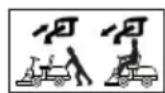
- Carrying other people, children or animals on the machine or on a trailer.
- Towing or pushing loads without using the proper towing accessory.
- Using the machine to travel over unstable, slippery, frozen, pebbly or potholed terrain or puddles or marshes which do not allow the user to accurately assess the solidity of the ground.
- activation of the cutting devices on grass-free areas.

Improper use will render the warranty null and void and the Manufacturer shall be exonerated from all liability, with all responsibility for damages or injuries to self or third parties being transferred to the user.
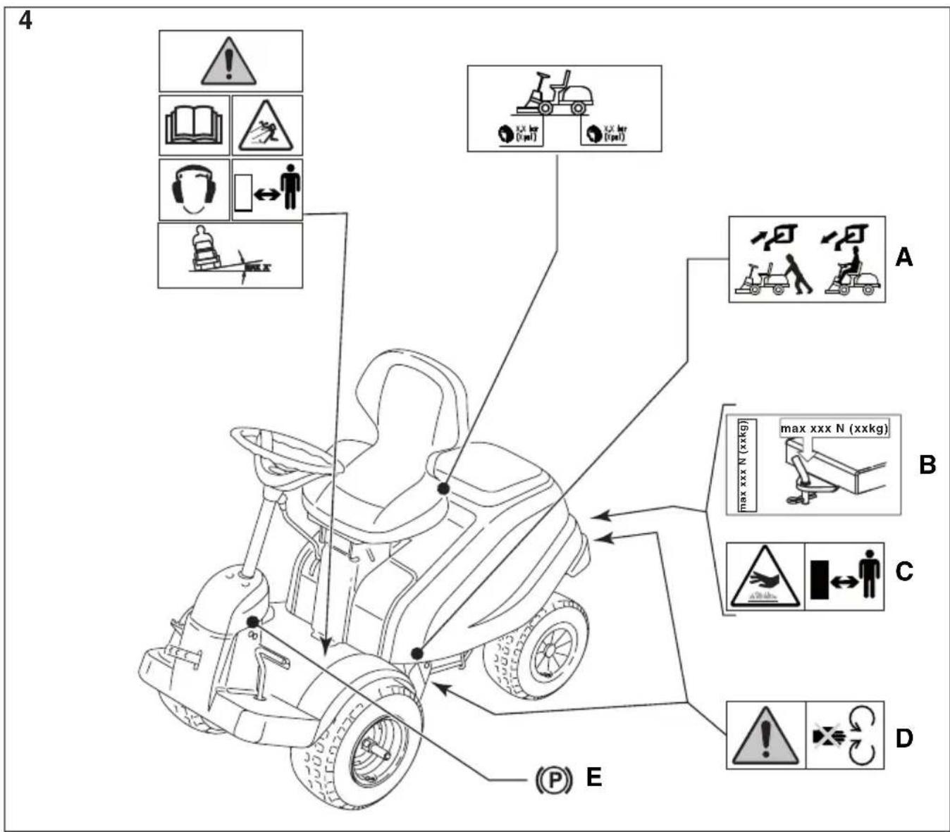
2.5 SAFETY SIGNS
Safety signs on the machine are designed to inform the user as to the correct conduct to be maintained when using the machine, in particular for operations which require special caution and attention.

WARNING! Indicates a hazard. It is usually accompanied by other symbols indicating the type of hazard.

Warning! Read the instruction manual before using the machine.

Warning! Watch out for any loose objects on the ground. Pay attention to any other people who may be in the area.
Warning! Always wear hearing protectors.

Warning! The machine has not been approved for use on public roads.

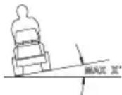
Warning! The machine, equipped with original accessories, must not be driven in any direction on slopes with a gradient greater than 10^ .
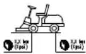
Tyre pressure. The decal shows the optimum tyre pressure values - see cap. "0 TECHNICAL DATA TABLE". Correct tyre pressure is an essential condition for achieving the best performance from your machine.
2.5.1 Decals (4)

Indicates parking brake blocking.
Indicates transmission engaging / release (5:A).
The decal is located:
- near the transmission engage/release lever.
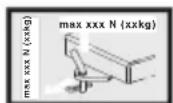
Indication of the maximum towable weight (4:B).
The decal is located:
- near the tow bar.

Warning! Burns hazard (4:C). Do not touch the silencer.
The decal is located:
- near the exhaust pipe.

Warning! Risk of crushing injuries (4:D). Keep hands and feet well away from the articulated steering joint and the towing hook when it is connected to an accessory.
The decal is located:
• near the articulated steering joint;
- near the tow bar.

Any damaged or illegible decals must be replaced.

Order replacement decals from an authorised assistance centre.
2.6 PRODUCT IDENTIFICATION LABEL
The identification label holds the following data (see fig. 1):
- Manufacturer's address
- Type of machine
- Sound power level
- CE conformity marking
- Weight in Kg
- Engine operating speed and power
- Year of manufacture
- Serial number
- Article code

Write your machine's serial number in the space provided in the figure (1:10).
The identity of the product is determined by two parts:
- The machine's item and serial numbers:
- The engine's model, type and serial numbers:

Use these means of identification whenever you contact an authorized service workshop.

The example of the declaration of conformity can be found on the second to last page of this manual.
2.7 MAIN COMPONENTS (1)
The machine is made up of the following main components (see fig. 1):
A. Chassis
B. Wheels
C. Steering wheel
D. Seat
E. Dashboard
F. Control pedals
G. Front accessories lift lever
H. Bonnet
I. Engine
L. Fuse box
M. Battery
N. Fuel tank
O. Fixed mounts for accessories
3 SAFETY REGULATIONS

Read these instructions carefully before using the machine.
3.1 TRAINING

CAUTION! Read these instructions carefully before using the machine.
Be familiar with the controls and the proper use of the machine.
Learn to stop the machine and disengage the controls quickly.
Failure to observe the warnings and instructions may lead to electric shock, fire and/or serious injury.
Please keep all the warnings and instructions for future reference.

Never allow children or people unfamiliar with these instructions to use the machine.
Local regulations may restrict the age of the operator.

Never use the machine when bystanders, especially children, or pets are in the surroundings.

Never use the machine if the user is tired or unwell, or has taken medicine, drugs, alcohol or substances which may slow his reflexes and compromise his judgement.

Keep in mind that the operator or user is responsible for accidents or hazards occurring to other people or their property.
It is the user's responsibility to assess the potential risk of the area where work is to be carried out, and to take all the necessary precautions to ensure his own safety and that of others, particularly on slopes or rough, slippery and unstable ground.

In the event of changes in ownership or loan of the machine, make sure the future user reads the instructions for use provided in this manual.

Never carry children or other passengers on the machine: they might fall off and be seriously injured or inhibit safe use of the machine.

The operator of a machine must carefully follow the driving instructions, particularly:
a. the need for care and concentration when using machines;
b. that control of a machine sliding on a slope will not be regained by the application of the brake. The main cause behind a loss of machine control are:
• insufficient wheel grip;
- being driven too fast;
- inadequate braking;
- the type of machine is unsuitable for its task;
- lack of awareness of the effect of ground conditions, especially slopes;
- Incorrect use of the machine as a towing vehicle;

The machine is equipped with a series of safety microswitches and devices which must never be removed, altered or tampered with. Removing these devices invalidates the warranty and the manufacturer declines any responsibility. Always check the safety devices work before using the machine.
3.2 PREPARATION
- When using the machine always wear sturdy, slip-resistant footwear and long trousers.
- Never activate the machine when barefoot or wearing open-toe sandals.
- Do not wear chains, bracelets, cumbersome clothing with strings or ties.
- Tie back long hair. Always wear hearing protectors.
- Thoroughly inspect the area where the equipment is to be used and remove all objects which may be thrown by the machine (stones, sticks, metal wire, bones, etc.)

CAUTION: DANGER! The fuel is highly flammable.
a. store fuel in containers specifically designed for this purpose;
b. refuel using a funnel and outdoors only. Do not smoke while refuelling or whenever handling the fuel;
c. Add fuel before starting the engine. Never remove the cap of the fuel tank or add fuel while the engine is running or when the engine is hot;
d. If fuel is spilled, do not attempt to start the engine but move the machine away from the area of spillage and avoid creating any source of ignition until the fuel has evaporated and the fumes dispersed;
e. Always replace caps of fuel tanks and container securely.

Replace faulty silencers.

Before using, always carry out a visual inspection, particularly of the cutting device, seeing that the screws and cutting devices are not worn or damaged. Replace a worn or damaged cutter blade and screws as a set to preserve balance.
Any repair shall be performed by an authorized service centre.

Check the condition of the battery at frequent intervals. Replace if damages to the casing, cover or terminals are found.
3.3 DURING OPERATION

Never start the engine in a confined area where hazardous carbon monoxide gases can build up.
All starting operations have to be effected in an open or well ventilated area!
Always remember that exhaust gases are toxic!

Mow only in daylight or with good artificial light in good visibility conditions.
Keep persons, children and animals away from the working area.

If possible, avoid mowing wet grass. Avoid working in the rain and when there is a thunderstorm risk. Do not use the machine in bad weather, especially if there is a risk of lightning.

Before starting the engine, disengage the cutter blade or the PTO and put the gear into neutral.

Take special care when approaching obstacles which may obscure your vision.

Apply the parking brake when you park the machine.

The machine may not be driven on slopes greater than 10^ (17%), in any direction.

Remember there is no such thing as a "safe" slope. Travel on grass slopes requires particular care. To avoid roll-over of losing control of the machine:
a. do not stop or start suddenly when going up or downhill;
b. engage the drive slowly and always keep the machine in gear, especially when travelling downhill;
c. machine speeds should be kept low on slopes and during tight turns;
d. Beware of humps, hollows and other hidden dangers;
e. Never mow across the face of the slope. When mowing on a slope, proceed up and down the slope as opposed to across it, taking great care when changing direction that the first wheels do not hit obstacles (such as stones, branches, roots, etc.), that may cause the machine to slide sideways, roll over or otherwise cause loss of control.

Reduce speed before any change of direction on slopes and always engage the parking brake before leaving the machine stopped and unattended.

exercise caution in the proximity of cliffs, ditches or embankments. The machine may overturn if a wheel drives over the edge or the edge gives way.

Exercise maximum caution when reversing and working in reverse. Look behind you both before and during reversing to make sure there are no obstacles.

Use care when pulling loads or using heavy equipment:
a. use only approved drawbar hitch points;
b. limit loads to those you can safely control;
c. Do not make any sudden turns. Use care when reversing;
d. use counterweight(s) or wheel weights whenever advised in the instructions manual.

Disengage the cutter blade or PTO and lift the cutting deck assy to its highest position when crossing grass-free areas or when moving from one area to another.

Look out for traffic when using the machine near the road.

CAUTION! The machine has not been approved for use on public roads. It has to be used (as indicated by the highway code) in private areas closed to traffic.

Never use the machine if the safe-guards are damaged.

Do not put hands or feet near or under rotating parts. Keep clear of the discharge opening at all times.

Do not leave the machine on high grass with the engine running to avoid the risk of starting a fire.

When using accessories, always direct the discharge chute away from people.

Only use accessories approved by the machine manufacturer.

Do not use the machine if the accessories/tools are not installed in the correct places. Driving without accessories may adversely effect machine stability.

Take care when using grass collectors and other accessories which may alter machine stability, especially when working on a slope.

Do not change the engine governor settings or overspeed the engine.

Do not touch engine components which get hot during use. Burns hazard.

Disengage the cutter blade or the PTO, set the engine to the idle position, stop the engine and remove the key (make sure that all moving parts have come to a complete stop):
a. whenever you leave the machine unattended or leave the driver'r seat.
b. before removing the jamming cause or unclogging the collector channel;
c. before checking, cleaning or working on machine;
d. after striking a foreign object. Inspect the machine for damage and make repairs before restarting and operating the machine;

Disengage the cutter blade or the PTO and stop the engine (make sure that all moving parts have come to a complete stop):
a. Before refuelling;
b. Every time you remove the grass collector sack or put it back on;
c. adjusting the cutting height, assuming this operation cannot be done from the driver's seat.

Disengage the cutting blade or the PTO during transport or whenever the machine is not being used.

Reduce the throttle setting before stopping the engine. turn the fuel off at the conclusion of mowing, following the instructions in the manual.

Take care with multiple blade cutting decks as one rotating blade may cause other blades to rotate.

WARNING - In the event of failures or accidents when working with the machine, stop the engine immediately and move the machine away to avoid causing further damage; in the event of accidents with injuries to operators or third parties, take the first aid measures which are most appropriate to deal with the situation and contact a health care facility for the necessary treatment. Carefully remove any debris which could cause damage or injury to persons or animals if ignored.

CAUTION! The noise and vibration levels shown in these instructions are
the maximum levels for use of the machine. The use of an unbalanced cutting element, the excessive speed of movement, or the absence of maintenance have a significant influence on noise emissions and vibrations. Consequently, it is necessary to take preventive steps to eliminate possible damage due to high levels of noise and stress from vibration. Maintain the machine well, wear ear protection devices, and take breaks while working.
3.4 MAINTENANCE AND STORAGE

CAUTION! - Before cleaning or doing maintenance work, take out the ignition key and read the relevant instructions. Wear adequate clothing and work gloves whenever your hands are at risk.

CAUTION! - Never use the machine with worn or damaged parts. Faulty or worn-out parts must always be replaced and never repaired. Only use original spare parts: The use or non-original and/or incorrectly fitted parts will compromise the safety of the machine, may cause accidents or personal injuries for which the Manufacturer is under no circumstance liable or responsible.

Any regulations and maintenance operations not described herein must be carried out by your Dealer or Authorized Service Centre, which have the necessary knowledge and equipment to ensure that the work is carried out correctly, maintaining the correct degree of safety and the original operating conditions of the machine. Any adjustments or maintenance operations carried out by people not having the necessary knowledge will nullify the warranty and exonerate the manufacturer from all liability.
• After each use of the machine, remove the key and check for any damage.
- Keep all nuts, bolts and screws tight to be sure the equipment is in safe working condition. Regular maintenance is essential for safety and for maintaining performance levels.
- Regularly check that the cutting deck blade screws are securely tightened.

Wear suitable work gloves when handling the cutter blade assy during removal and reinstallation operations.

Check the cutting blade's balance after sharpening. All operations concerning the cutting deck assy (disassembling, sharpening, balancing, assembling and/or replacement) are tough works and require a specific knowledge as well as special tools; for sake of safety, they should always be performed by an authorized service centre.
- Regularly check the brakes work properly. It is important to service the brakes and repair them if necessary.
- Frequently check the grass collector for wear and damage.
- Replace any damaged warning and instruction stickers.
- If the machine has no mechanical stoppers for transport, accessories must always be resting on the ground when the machine is parked, stored or left unattended.
- Store the machine where children cannot get to it.

Never store the equipment with fuel in the tank inside a building where fumes may reach a flame or a spark or a source of extreme heat.
- Allow the engine to cool before storing in an enclosed space.
- To reduce the fire hazard, keep the engine, exhaust silencer, battery compartment and fuel storage area free of grass, leaves, or excessive grease.
- To reduce the risk of fire, regularly check the machine for oil and/or fuel leaks.
- If the fuel tank has to be drained, this should be done outdoors and when the engine is cool.
- The ignition key must never be left inserted in the machine, or where children or persons not familiar to the machine may reach it. Before any maintenance or repair, remove the ignition key.

CAUTION! – Battery acid is corrosive. In the event of mechanical damage or overcharging, acid may leak out. Avoid inhalation or contact with any part of the body.

Inhaled acid fumes are harmful to mucous membranes and other internal organs. Seek medical attention immediately.

CAUTION! – Do not overcharge the battery. Excessive charging may cause the battery to explode with subsequent acid leaks.

CAUTION! – Acid can seriously damage tools, clothing and other materials. Rinse away spilled acid immediately with water.

Do not short circuit the battery terminals. Sparks occur which can result in fire.

TAKE CARE over the hydraulic components. Pressurized hydraulic fluid leaks may lead to injection injuries which can seriously damage tissues and need immediate medical attention.
3.5 TRANSPORTING

CAUTION! - If the machine is transported on a truck or trailer, use ramps with suitable resistance, width and length. Load the machine with the engine switched off, without a driver and pushed by an adequate number of people
During transport, close the fuel stopcock (if fitted), lower the cutting deck assy or the accessory, engage the parking brake and fasten the machine securely with ropes or chains to the hauling device.
3.6 ENVIRONMENTAL PROTECTION
- Safeguarding the environment must be a relevant and priority aspect of machine use, of benefit to the community and the environment we live in. Avoid being a disturbance to the neighbourhood.
-
Adhere strictly to the local regulations governing the disposal of packaging, oil, fuel, filters, damaged parts or any other element which may have an impact on the environment; this waste should not be disposed of along with standard household waste, but must be disposed of separately and sent to special waste disposal facilities for handling and recycling.
-
Adhere strictly to local regulations governing the disposal of cuttings.
- When the machine is withdrawn from service, do not dump it in the environment, but take it to a waste disposal facility in accordance with the local regulations in force.
4 INSURING YOUR LAWNMOWER
Check the insurance on your lawnmower.
Contact your insurance company.
You ought to have fully comprehensive insurance for traffic, fire, damage and theft.
5 ASSEMBLY

The battery must be fully charged before being used for the first time.

Do not use the machine until all the indications provided in the "ASSEMBLY" section have been carried out.

Unpacking and completing the assembly should be done on a flat and stable surface, with enough space for machine handling and its packaging, always making use of suitable equipment.
5.1 ASSEMBLY COMPONENTS (3)
The machine is delivered with the seat, armrests, steering wheel, tow bar, quick-fit supports dismantled. The battery is in its housing but not connected.
The packaging holds the components needed for assembly (3) as listed in the table below:
| Pos. No | Description Dimensions | ||
| Contents of the bag | |||
| A 1 Tow | bar / | ||
| B 2 Flanged screw | 8 x 20 | ||
| C | 2 Screw for battery | / | |
| D | 2 Nut for battery | / | |
| E 6 Washer | 8,4 x 24 x | 2,0 | |
| F | 2 Shoulder washer | / | |
| G | 4 Screw | 8 x | 20 |
| H | 2 Screw knob | / | |
| I | 2 Ignition key | / | |
| J | 1 Pin | 6 x | 36 |
| K 1 Shim | 16 x 38 x0,5 | ||
| L | 1 Shim | 16 x | 38 x 1,0 |
| P 2 Screw | M10 x 35 | ||
| Q | 2 Nut | M10 | |
| R | 2 Split lock washer | 14 x 8,2 x 2 | |
| Installed on the front semi-axles | |||
| M | 2 Safety rings | / | |
| N | 2 Washer with internal wing | / | |
| Attached to the tool lift | |||
| O | 2 Deck mount | / | |
5.2 BONNET(5:A)

Open the bonnet to access the fuel cock, battery and engine.
The bonnet can be opened as follows:
[Gear]
- Set the lever (12:A; 12:B) to the forward position.
[Hydrostatic]
- Set the lever (13:A) to the forward position.
- Lift the seat stopper (7:S) and fold the seat forward.
- Open the bonnet: take hold of the edge (5:A) and lift.
- Perform the above operations in reverse order to close the bonnet.
![STIGA Villa 15 HST - [Hydrostatic] - 1](/content/2026/03/518154/images/2c4a541e202a06eff59c95372020bf0d698081cd3749ca68eddcb276b682b5c1.jpg)
It is strictly prohibited to start the engine when the bonnet is open.
5.3 BATTERY
For the type of battery installed on the machine, please refer to "0 TECHNICAL DATA TABLE"

CAUTION! Battery acid is corrosive and contact with it is harmful. Handle the battery with care taking care not to let acid leak out.

Do not check or top up the battery fluid.
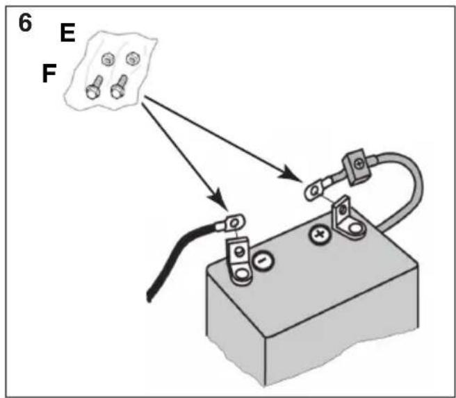
5.3.1 Battery connection (6)
Connect the battery to the machine's electrical system using the relative screws and nuts (6:F; 6:E):
- Connect the red cable to the battery's positive terminal (+).
- Connect the black cable to the battery's negative terminal (-).

If the leads are disconnected/connected in the wrong order, there is a risk of a short-circuit and damage to the battery.

Inverting the cable connections will damage the alternator and the battery.

Tighten the cables securely. Loose cables can cause a fire.

The engine must never be driven with the battery disconnected. There is a risk of serious damage to the alternator and the electrical system.
5.3.2 Battery charging

The battery must be fully charged before being used for the first time.

Please refer to 9.9 for the battery charging procedure.
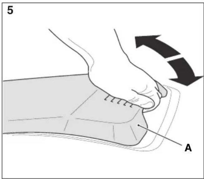
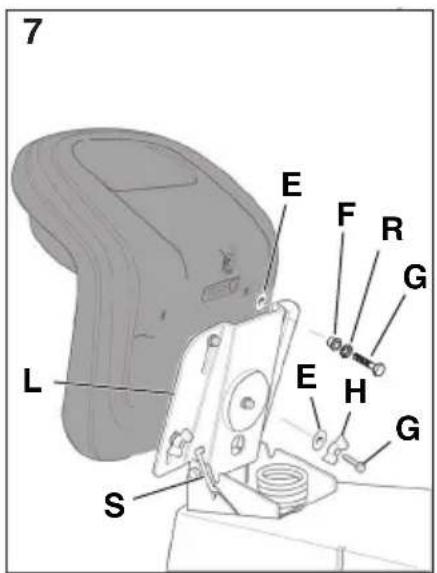
5.4 SEAT (7)
Release the seat stopper (6:S) and tilt the seat bracket (7:L) up.
Install the support in the front (top) holes as follows:
- Put the shoulder washers (7:F) on the screws (7:G), complete with washers (7:R).
- Insert the screws, complete with shoulder washers, in the slots in the seat bracket. Put the set in the washers (7:E) and in the holes in the seat plate. Screw the seat into place.
Tightening torque: 9 ± 1.7 Nm.

Tightening the screws to a torque over 9 ± 1.7 Nm, will damaged the seat.
- Check that the seat moves easily in the slots in the bracket.
Install the support in the front (top) holes as follows:
- Put the knobs (7:H) on the screws (7:G).
- Put a washer (7:E) on each screw.
- Insert the screws in the slots on the bracket and tighten manually.
- Fold the seat back down and set it in the desired position.
- Tighten the knobs (7:H) by hand.

The knobs (7:H) and the seat will be damaged if tools are used.
The seat can be folded. If the machine is parked outside where it is exposed to rain, fold the seat forward to protect the seat cushion from getting wet.
The seat is locked in place. To lift or lower the seat, first release the stopper (7:S).
The seat can be folded. If the machine is parked outside where it is exposed to rain, fold the seat forward to protect the seat cushion from getting wet.
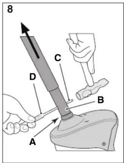
5.5 STEERING WHEEL (8)
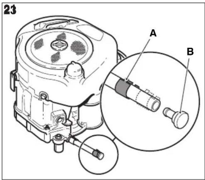
In order to minimise axial play in the steering column, place the 0.5-mm and/or 1-mm shim/s (3:K; 3:L) on the steering column between the sleeves, pos. (8:A) as follows:
- Install the sleeve (8:B) on the steering column and secure in place by inserting one of the pins (8:C) by approximately 1/3 of its length.
- Pull the sleeve and steering column upwards.
- Check that the 0.5-mm shim, the 1.0-mm shim (or both) can be inserted into the gap which is created in point (8:A).. The shim/s must not be forced in, as there must be a little axial play.
- Remove the pin (8:C) using a pin punch (8:D) and remove the sleeve.
- Install the shim/s as indicated in point 3 above.
- Install the sleeve on the steering column and secure by inserting both pins completely. Block the steering column.
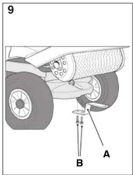
5.6 TOWING DEVICE (9)
Screw the towing device (10:A) into the two holes on the bottom side of the rear axle.
Use the screws and nuts (10:B).
Tightening torque: 22 Nm.
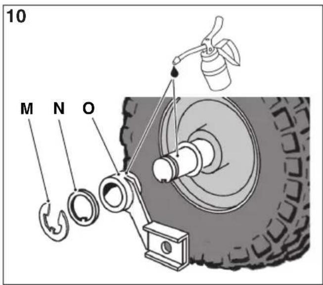
5.7 FIXED MOUNTS FOR CUTTING-MEANS ASSEMBLY HOOK-UP (10)
Only installation on the right semi-axle is described. Perform the same procedure for the left semi-axle..
-
Remove the circlip (10:M) and the external washer (10:N).
-
Install the cutting-means assembly mount (10:O).

The washer (10:N) with internal wing must always be in contact with the circlip. If this is not the case it may come loose..
- Install the external washer (10:N) and the circlip (10:M).
- Lubricate the lubrication sump of the cutting-means assembly mount using a grease syringe until grease penetrates the length of the semi-axle.
Use the screws (3:P) and the nuts (3:Q) to install
the work tool in the cutting-means assembly arms (10:O).
5.8 TYRE PRESSURE
For the tyre pressure, please refer to chap. "0 TECHNICAL DATA TABLE".
5.9 ACCESSORIES
For installation of accessories, see the installation guide accompanying each accessory.

Note: In this case the cutting device assy is considered an accessory.
6 CONTROLS
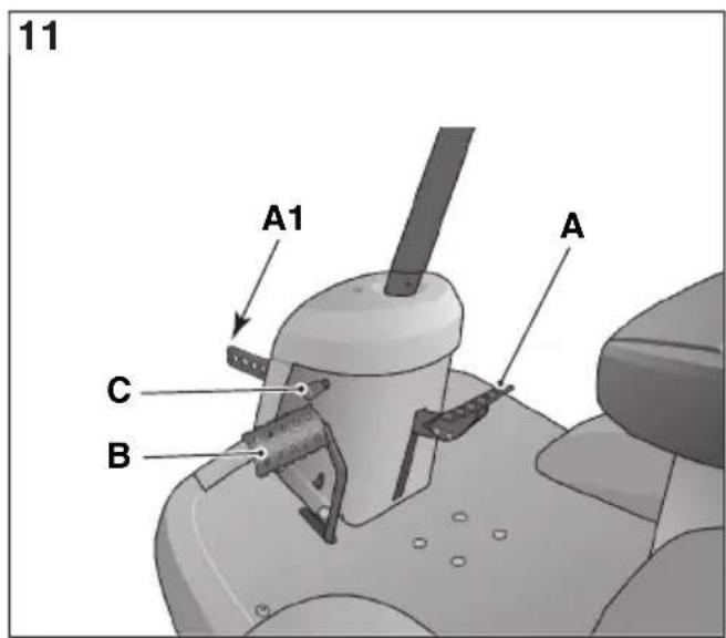
6.1 MECHANICAL ACCESSORY LIFT PEDAL (11:A)
The control lever (11:A1) is used to take the accessories from the operating position to the transport position.
- Transport position: press the pedal right down then lift your foot off: the pedal stays down.
- Working position: press and slowly release the pedal.

Do not attempt to switch to the transport position while the hooked-up accessory is in operation. This will destroy the drive belt.
6.2 PARKING BRAKE PEDAL mod.:[Gear] (11:B)
Combined brake/clutch pedal. The pedal (11:B) has the following three positions:
![STIGA Villa 15 HST - PARKING BRAKE PEDAL mod.:[Gear] (11:B) - 1](/content/2026/03/518154/images/7ac01da75fd2b8a49fec0901f700cf30375e2524043cc81dcef90d68a2857a14.jpg)
Released: Forward drive engaged. If the machine is in gear and the pedal is released, the machine will move accordingly. The brake
is not on.
Pressed to halfway: Forward drive disengaged. In this position it is possible to change gear. The brake is not on.
Pressed right down. Forward drive disengaged. The brake is on.
![STIGA Villa 15 HST - PARKING BRAKE PEDAL mod.:[Gear] (11:B) - 2](/content/2026/03/518154/images/29796bb01c8ff80d0673d54944c21d3b2bbdf3a381698cafa197bb3e82df36e6.jpg)
Do not regulate driving speed by acting on the clutch pedal and letting it slip. Put the machine a more suitable gear.
6.3 PARKING BRAKE MODELS: [Hydrostatic] (11:B)
The pedal (11:B) has the following three positions:
![STIGA Villa 15 HST - PARKING BRAKE MODELS: [Hydrostatic] (11:B) - 1](/content/2026/03/518154/images/27df0c8e339b3603b6152c2ac82e33811d11d380d7cf03c38972b4d595fc2ae3.jpg)
Released: The clutch is not activated. The parking brake is not activated.
Pressed to halfway: Forward drive disengaged. The parking
brake is not activated.
Pressed right down. Forward drive disengaged. The parking brake is fully activated but not locked. This position is also used as an emergency brake.
The lever locks the “brake” pedal in the pressed right down position. This function is used to lock the machine on slopes, dunsport, etc., when the engine is not running.
Locking:
- Press the pedal (11:B) right down.
- Move the locking lever (11:C) to the right.
- Release the pedal (10:B).
- Release the locking lever (11:C).
Unlocking:
- Press and release the pedal (10:B).
6.5 TRACTION PEDAL [Hydrostatic] (13:E)
The pedal determines the gearing ratio between the engine and the drive wheels (= the speed). When the pedal is released, the service brake is activated.
![STIGA Villa 15 HST - TRACTION PEDAL [Hydrostatic] (13:E) - 1](/content/2026/03/518154/images/bfdd6fd61e22eff38f0c9ac64b7ec1e3bb2fa3e7155f319d830390cac28864e9.jpg)
(○) - Press the pedal forward – the machine moves forward.
- No load on the pedal – the machine is stationary.
(○) - Press the pedal backward – the machine reverses.
- Reduce the pressure on the pedal – the machine brakes.
A plate is installed on the upper section of the pedal which can be adjusted to suit the driver's foot.
![STIGA Villa 15 HST - TRACTION PEDAL [Hydrostatic] (13:E) - 2](/content/2026/03/518154/images/879f490602a117694f69c19a911e8ffcecca204e13fbd39f66520478bbc483e2.jpg)
If the machine does not brake as expected when the pedal is released, the left pedal (11:B) should be used as an emergency brake.
6.6 STEERING WHEEL (If scheduled) (13:H)
The height of the steering wheel is fully adjustable. Unscrew the adjustment knob (13:D) on the stee-
ring column and raise or lower the steering wheel accordingly. Tighten.

Do not adjust the steering wheel when the machine is running.

Never turn the steering wheel when the machine is stationary with a lowered accessory. There is a risk of abnormal loads on the servo and steering mechanisms.
6.7 THROTTLE AND CHOKE CONTROL (12:D, 13:C)
A control for regulating the engine speed and using the choke when starting the engine in cold conditions.

If the engine runs unevenly (alternate variation in the number of engine revs) the control may be too far forward, thus activating the choke. This damages the engine, increases fuel consumption and is harmful to the environment.

Choke – for starting the engine in cold conditions. Do not use this position when the engine is warm.

Full throttle – should always be used when the machine is in use. The full throttle position is approximately 2 cm behind the choke position.

Idling.

The ignition block is used for starting and stopping the engine.

Do not leave the ignition key in position 2 when you leave the driving seat. There is a risk of fire (fuel can run into the engine through the carburettor) and the battery may go flat and get damaged.
The three ignition key positions:

- Stop position – the engine is short-circuited. The key can be removed.

2. Driving position

- Start position – the electric starter motor is activated when the key is turned to this position. Once the engine has started, let go of the key which will return to the driving position 2.
6.9 GEAR LEVER - MODELS: [Gear] (12:B)
Lever for selecting one of the five forward gears (1-2-3-4-5), neutral (N) and reverse (R).
To change gear, press the clutch pedal right down.
![STIGA Villa 15 HST - GEAR LEVER - MODELS: [Gear] (12:B) - 1](/content/2026/03/518154/images/7eb165eadc90d65b655e647ec03a855ea6bc914b88c1cd60401f08eeb67da992.jpg)
NOTE! Make sure the machine is stationary before changing from reverse to forward and vice versa. If the gear does not engage, release the clutch pedal and press it down again. Try again to put the machine into gear. Never force the gears.
6.10 POWER TAKE-OFF (12:A; 13:A)
A lever for engaging and disengaging the power take-off for operating front-mounted accessories.

The PTO must never be engaged when the front accessory lift is in the transport position. This will destroy the belt drive.

Lever forward – PTO disengaged.

Lever back – PTO engaged.
6.11 CUTTING HEIGHT ADJUSTMENT (13:G)
The machine is equipped with a control for using the cutting device with electrical cutting height adjustment.

The switch allows the user to continuously adjust the cutting height.
The cutting deck is connected to the contact (13:F).
6.12 TRANSMISSION RELEASE LEVER - MODELS: [Hdrostatic] (15:A)
This lever disengages hydrostatic transmission.
![STIGA Villa 15 HST - TRANSMISSION RELEASE LEVER - MODELS: [Hdrostatic] (15:A) - 1](/content/2026/03/518154/images/1e33e76dcddf1c228e01a77248fb02b467e7ffe124950110f2336a529958e7b6.jpg)
The disengagement lever must never be between the outer and inner positions. This overheats and damages the transmission.
The levers allow the user to move the machine manually (pushing or pulling), without the engine running. The two positions are:
![STIGA Villa 15 HST - TRANSMISSION RELEASE LEVER - MODELS: [Hdrostatic] (15:A) - 2](/content/2026/03/518154/images/e404bf059ddc9ebe8ca81ecfdb94ccaeae038da0520eb1721469be7651e734f4.jpg)
-
Lever in - transmission engaged for normal use. Locking of the lever in this position is indicated by a click.
-
Lever out - transmission disengaged. The machine can be moved by hand.
The machine must not be towed over long distances or at high speeds. The transmission could be damaged.
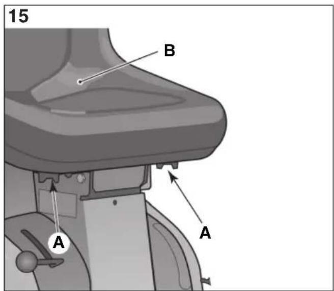
6.13 SEAT ADJUSTMENT (15:A)

The seat is foldable and can be moved backwards and forwards to suit the driver.
To set the seat in the desired position:
- Slacken the knob (15:A) without using any tools.
- Move the seat to the desired position.
- Retighten the knob (14:A) manually.

The knobs (15:A) and the seat (15:B) will be damaged if tools are used.
The seat is equipped with a safety switch that is connected to the machine's safety system. This means that certain dangerous activities cannot be performed unless someone is actually in the seat (see 7.6.2).
6.14 BONNET

See 5.2 for how to access the fuel cock, battery and engine.
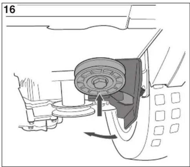
6.15 BELT TENSIONER BLOCKING (16)
When the an accessory is installed on the machine which does not need any motorization, the belt tensioner must be blocked as follows (if the machine is fitted with a blocking lever):
- Pull the tensioner towards the outside (i.e. move it towards the safety guard).
- Block the tensioner by turning the blocking lever clockwise.
7 START-UP AND OPERATION
7.1 PRECAUTIONS FOR USE

Always make sure the engine oil level is correct. This is particularly important when operating on slopes (see 7.4).
Pay attention when mowing on slopes: avoid abrupt starts and stops, do not run the machine transversally to the slope but run from top to bottom and vice versa.
Apply the parking brake when you park the machine.

The machine may not be driven on slopes greater than 10^ in any direction.

Reduce the speed on slopes and when making sharp turns in order to retain control of the machine and reduce the risk of overturning.

Do not turn the steering wheel to full lock when driving at full speed. The machine may overturn.

Keep hands and feet well away from the articulated steering joint and seat bracket. Risk of crushing injuries.

Do not drive the machine with the cutting-means assembly in the transport position as this will damage the drive belt.
7.2 COMBINED USE OF ACCESSORIES

For the combined use of accessories, please refer to the "TABLE FOR THE CORRECT COMBINATION OF ACCESSORIES" in section "0 TECHNICAL DATA TABLE"
7.3 REFUELLING

Before refuelling, turn off the engine, apply the parking brake and remove the key from the ignition.

Always use lead-free petrol only. DO NOT mix petrol with oil.
For the capacity of the fuel tank, please refer to "0 TECHNICAL DATA TABLE" The transparency of the tank allows the user to check the level easily.

NOTE! Petrol is perishable and should not remain in the tank for more than 30 days.
It is possible to use ecological fuels, i.e. alkylate petrol. The composition of these petrol is less harmful to people and the environment.
No negative effects linked to use of the same have been reported. However, there are types of alkylate-based petrol available on the market for which it is not possible to give precise indications regarding their use.
For further information it is advisable to consult the instructions and data provided by the producer of the alkylate-based petrol.
Never fill the tank right to the top.
Leave a little space (equal to at least the whole depth of the top-up mouth + 1 - 2 cm from the top of the tank) so that when the petrol heats up it has room to expand without overflowing.

If you plan on putting the machine away for a prolonged period (e.g. over the winter), only put enough fuel in the tank to finish the last job in hand.
In fact, before storing the machine it is a good idea to empty the fuel tank completely (see 10).
7.4 CHECKING THE ENGINE OIL LEVEL (18; 19; 19A)
The machine is delivered complete with engine oil.

Before starting the machine check the level of the engine oil.

To check / top up the engine oil, see 9.5.1.
7.5 SAFETY CHECKS
When trying out the machine, check that the results of the safety checks correspond with the indications provided in the following tables.

Always carry out the safety checks before use.

If any of the results fails to match the indications provided in the following table, do not use the machine!
Take it to a service centre to be checked and repaired if necessary.
7.5.1 General safety check
| Object Result | |
| Fuel lines and connections. | No leaks. |
| Electrical cables All | insulation intact.No mechanical damage. |
| Exhaust system. No | leaks at connections. All screws tightened. |
| Oil lines No leaks. No damage. | |
| Drive the machine forwards/backwards and release the driving pedal. | The machine will stop. |
| Test driving No abnormal vibrations.No abnormal sound. | |
7.5.2 Electrical safety check
| Status Action Result | ||
| The clutch-brake pedal is not pressed.The PTO is not activated. | Try to start the machine. | The engine does not start. |
| The gear selector is not in neutral positionThe PTO is activated.. | Try to start the machine. | The engine will not start. |
| Engine switched on. The PTO is activated. | The driver gets off the seat | The engine will not start. |
| Engine switched on. The PTO is activated | The driver gets off the seat | The engine will not start. |
| Engine switched on. | Remove the 20A fuse (1:L). | The engine stops |
When using the machine, the bonnet must be closed and fastened shut.

Always use full throttle when using the machine.

When starting the machine, wait for 2 seconds in starting position before starting the engine.
- Open the fuel cock (16).
- Check that the spark plug cables are installed on the spark plugs.
- Check the PTO is disengaged (12:A; 13:A).
- Do not keep your foot on the service/drive brake (10:F)
Cold start
- Engage the transmission (14:A)
- Activate the parking brake (11:B)
- Put the choke on (where applicable) (12:D; 13:C).
- Turn the key in the ignition and start the engine.
- When the engine is running, gradually accelerate to maximum operating speed

Before starting work with the machine, wait a few minutes for the oil to warm up.
Warm start.
- Engage the transmission (14:A)
- Activate the parking brake (11:B)
- Turn the throttle to full on (12:D; 13:C).
- Turn the key in the ignition and start the engine.

To proceed see the instructions provided in heading 7.6.1.
7.6.1 Operation
To start the machine, proceed as follows:
Only for models: [Gear]
- Put into gear with the gear lever (12:B)
- Press the pedal (11:B) right down then release it.
- Activate the pedal (13:E) to move the machine.
- Go to the work area.
- If front accessories have been installed, activate the PTO (12:A; 13:A)
- Commence work.
7.7 STOPPING
To stop the machine, proceed as follows:
- Disengage the PTO (12:A; 13:A)
- Engage the parking brake (11:B)
- Allow the engine to idle 1-2 mins.
- Turn off the engine by turning the ignition key.
- Close the fuel cock. This is particularly important if the machine is to be transported on a trailer for example.

If you have to leave the machine unattended, disconnect the spark plugs and remove the key from the ignition.

The engine may be very warm immediately after it is shut off. Do not touch the silencer, cylinder or cooling fins. This can cause burn injuries.
7.8 CLEANING

To reduce the risk of fire, keep the engine, silencer, battery and fuel tank free from grass, leaves and oil To reduce the risk of fire, regularly check the machine for oil and/or fuel leaks.

Never use high-pressure water jets. This can damage shaft seals, electrical components or hydraulic valves.
Always clean the machine after use. To clean the machine adhere to the instructions provided below:
- Do not spray water directly onto the engine.
- Clean the engine with a brush and/or compressed air.
- Clean the motor cooling air intake.
- After cleaning using water, start the machine and any cutting device assy to remove any water which may otherwise end up in the bearings and cause damage.
8 USING THE ACCESSORY

Make sure the grass to be cut is completely free of foreign objects such as stones etc.
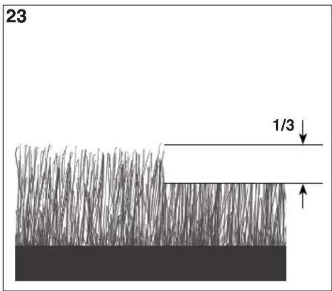
8.1 CUTTING HEIGHT
For best results, cut off the top third of the grass. See fig. 23.
If the grass is long and needs cutting back significantly, cut twice using two different cutting heights.
Do not use the lowest cutting heights if the lawn surface is uneven.
This would entail a risk of the cutting devices being damaged against the surface and the lawn's top layer of soil being removed.
8.2 MOWING TIPS
To get the best mowing results, follow the tips given below.
- Cut grass frequently.
- Run the machine at full revs.
- Grass should not be wet.
- Only use sharp cutting devices.
- Keep the bottom side of the cutting device clean.
9 MAINTENANCE
9.1 ASSISTANCE PROGRAMME
To keep the machine in good working order in terms of reliability, safety and environmental protection, always adhere to the STIGA SpA servicing programme.
The points of intervention for this programme are illustrated in the attached STIGA SpA maintenance manual.
The Basic Service must always be carried out by an authorized service workshop.
The First Service and Intermediate Service should be carried out by an authorized service workshop, but can also be carried out by the user.
The procedures are indicated in the handbook and are described in the chapter "7 START-UP AND OPERATION" as well as here below.
The checks carried out by an authorized service workshop guarantee professional workmanship and the use of genuine spare parts.
The handbook is stamped every time a Basic Service is performed and each time an Intermediate Service is carried out by an authorized service workshop. A handbook with these stamps increases the second-hand value of the machine.
9.2 PREPARATION

All service and all maintenance checks must be carried out on a stationary machine with the engine switched off.

Always apply the parking brake to stop the machine from moving.

Stop the engine.

Prevent inadvertent start-up of the engine by disconnecting the spark plug cables and removing the ignition key.
9.3 MAINTENANCE TABLE

See chapter "13 MAINTENANCE SUMMARY TABLE". The table is designed to help you keep your machine in efficient and safe working order. It indicates the main operations to be performed and the frequency of the same. Perform the relative operation described based on the first deadline to arrive.

Change the oil more frequently if the engine has to work in difficult conditions or when the ambient temperature is high.
9.4 TYRE PRESSURE
Adjust the tyre pressure to meet the values provided in "0 TECHNICAL DATA TABLE".
9.5 ENGINE OIL TOP-UP/CHANGE

For this maintenance operation, see also the manual for the engine supplied with the machine.
9.5.1 Inspection / top-up (18; 19; 19A)

Always check the fluid level before use. To check the level, make sure the machine is on even ground.

Wipe around the dipstick. Unscrew it and pull it out. Wipe the dipstick clean.
(18; 19) Push the dipstick down completely and screw in place.
Now unscrew and pull the dipstick up again. Read off the oil level.
(19A) Insert the dipstick completely without screwing it in place.
Now pull the dipstick up again. Read off the oil level.
Top up if the level is lower than the "FULL" mark (18; 19; 19A).

The oil level must never exceed the “FULL” mark. This results in the engine overheating. If the oil level exceeds the “FULL” mark, the oil must be drained until the correct level is achieved.
Change the oil more frequently if the engine has to work in difficult conditions or when the ambient temperature is high.
9.5.2 Oil change/filling (21)

For the frequency of this intervention see chapter 13.

For the type of oil to use please refer to "0 TECHNICAL DATA TABLE".
Use oil with no additives.
Change the oil when the engine is warm.

The oil may be very hot just after the engine has been switched off. Consequently allow the engine to cool down for a few minutes before proceeding to drain off the oil.
Proceed as follows:
- Place the machine on a flat surface.
- Apply the parking brake.
- Open the bonnet.
- Grab the clamp (21:A) on the oil drain hose. Use adjustable polygrip pliers or similar.
- Move the clamp 3-4 cm up the oil drain hose and pull out the plug (21:B).
- Collect the oil in a suitable vessel.

NOTE! Take care not to spill any oil on the drive belts.
- Hand the spent oil over to a disposal facility in accordance with local provisions.
- Replace the oil drain plug and move the clamp back over the plug.
- Clean up any spills.
- Remove the dipstick and fill with fresh oil. For the quantities of oil required, please refer to "0 TECHNICAL DATA TABLE".
- After filling up the oil, start the engine and leave it to idle for 30 seconds.
- Check there are no oil leaks.
- Stop the engine. Wait for 30 seconds and then check the oil level again as indicated in heading 9.5.1.
9.5.3 Replacing the oil filter (if present)

For this maintenance operation, see also the manual for the engine supplied with the machine.

For the frequency of this intervention see chapter 13.
For this maintenance operation it is recommended to contact an authorised assistance centre.
First drain the engine oil and insert the oil drain plug as described above. Then replace the oil filter as follows:
- Clean the area around the filter and dismantle the filter.
- Smear the gasket on the new filter with oil.
- Install the filter. First screw in the filter so that the gasket comes into contact with the engine. Then screw in the filter a further 1/2-3/4 turn.
- Continue with point 7 in accordance with the indications provided in 9.5.2.
9.6 REPLACING THE FUEL FILTER (18:A, 19:A; 19A:A)

For this maintenance operation, see also the manual for the engine supplied with the machine.

For the frequency of this intervention see chapter 13.
Check for fuel leaks once the new filter has been installed.
9.7 BELT TRANSMISSIONS CHECK
check that all belts are intact.

For the frequency of this intervention see chapter 13.
9.8 STEERING

For the frequency of this intervention see chapter 13.
9.8.1 Checks
With the machine stationary, gently turn the steering wheel back and forth. There must be no mechanical play.
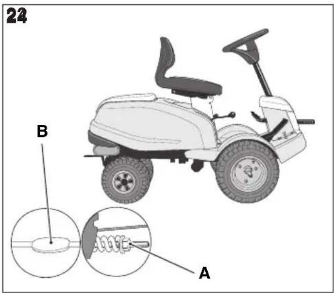
9.8.2 Adjust play in the steering wheel (22).
If necessary, adjust the steering cable as follows:
- Tension the steering cable by tightening the nut (22:A).

To stop the cable twisting, keep both ends of the screw still (22:B) throughout the adjustment operation. Use a spanner or similar adjustable tool, inserting it in the relative space on the screws at the ends of the cable.
- Adjust the nut until there is no play.

Do not over-tension the steering cable. This would make the steering too stiff and increase wear on the cable.
9.9 BATTERY
For the type of battery installed on the machine, please refer to "0 TECHNICAL DATA TABLE"

CAUTION! Battery acid is corrosive and contact with it is harmful.
Handle the battery with care taking care not to let acid leak out.

Acid can cause serious injuries if it comes into contact with eyes or skin. If any part of the body comes into contact with acid, rinse immediately with copious amounts of water and seek medical attention immediately.
The battery fluid does not need checking or topping up.
The only maintenance operation required is charging, for example after extended storage.
The battery can be charged:
- by the engine,
- by a battery charger.
9.9.1 Charging by the engine
This method is only an option if there is still enough charge in the battery to be able to start the engine.
- If the battery is new, connect the relative leads.
• Take the machine outside. - Start the engine by following the instructions provided in this manual.
- Leave the engine running continuously for 45 minutes (the time needed to fully charge the battery).
- Stop the engine.
9.9.2 Charging with a battery charger

Use a constant voltage battery charger. Use of a standard charger may damage the battery.
For further information, please contact your dealer.

Before connecting the battery charger, disconnect the battery from the electrical system.
9.9.3 Disassembly/assembly
The battery is housed under the bonnet.
During removal/installation of the battery, connect and disconnect the leads as follows:
- During removal. First disconnect the black lead from the battery's negative terminal (-). Then disconnect the red lead from the battery's positive terminal (+).
- During installation: First connect the red cable to the battery's positive terminal (+). Then connect the black cable to the battery's negative terminal (-).

If the leads are disconnected/connected in the wrong order, there is a risk of a short-circuit and damage to the battery.
Inverting the cable connections will damage the alternator and the battery.
Tighten the cables securely. Loose cables can cause a fire.
The engine must never be driven with the battery disconnected. There is a risk of serious damage to the alternator and the electrical system.
9.9.4 Cleaning
If the battery terminals are coated with oxide, they should be cleaned.
Clean the battery terminals with a wire brush and lubricate them with terminal grease.
9.10 AIR FILTER, ENGINE

For the frequency of this intervention see chapter 13.

For this maintenance operation, see also the manual for the engine supplied with the machine.

NOTE! The filters should be cleaned/replaced more often if the machine operates on very dusty ground.
9.10.1 Cleaning / Replacement - mod.: [B&S] (19)
Remove/install the air filters as follows:
- Clean carefully around the air filter housing (19:A).
-
Remove the air filter cover by unscrewing the two screws.
-
Remove the paper filter (19:B). Make sure that no dirt gets into the carburettor. Clean the air filter housing.
- Clean the paper filter by tapping it gently against a flat surface. If the filter is very dirty, replace it.
- Assemble the filter by performing the above instructions in reverse order.
Compressed air or petroleum-based solvents such as kerosene must not be used for cleaning the paper filter insert. This will damage the filter.
The paper filter insert must not be oiled.
9.10.2 Cleaning / Replacement - mod.: [STI-GA] (18)
Remove/install the air filters as follows:
- Carefully clean around the air filter cover.
- Remove the air filter cover (18:A) by removing the two clamps.
- Dismantle the filter assembly (18:D; 18:E). The prefilter is placed over the air filter. Make sure that no dirt gets into the carburettor. Clean the air filter housing.
- Clean the paper filter by tapping it gently against a flat surface. If the filter is very dirty, replace it.
- Clean the pre-filter. If the filter is very dirty, replace it.
- Assemble the filter by performing the above instructions in reverse order.
9.10.3 Replace the spark plug

For the frequency of this intervention see chapter 13.
Before removing the spark plug, clean around its mounting.
For the type of spark plug and relative spark gap, please refer to "0 TECHNICAL DATA TABLE".
9.10.4 Cleaning the air intake.

For the frequency of this intervention see chapter 13.
See figure (18:B; 19:B; 19A:B).
The engine is air-cooled.
A blocked cooling system can damage the engine. More meticulous cleaning of the cooling system should be carried out during each basic service.
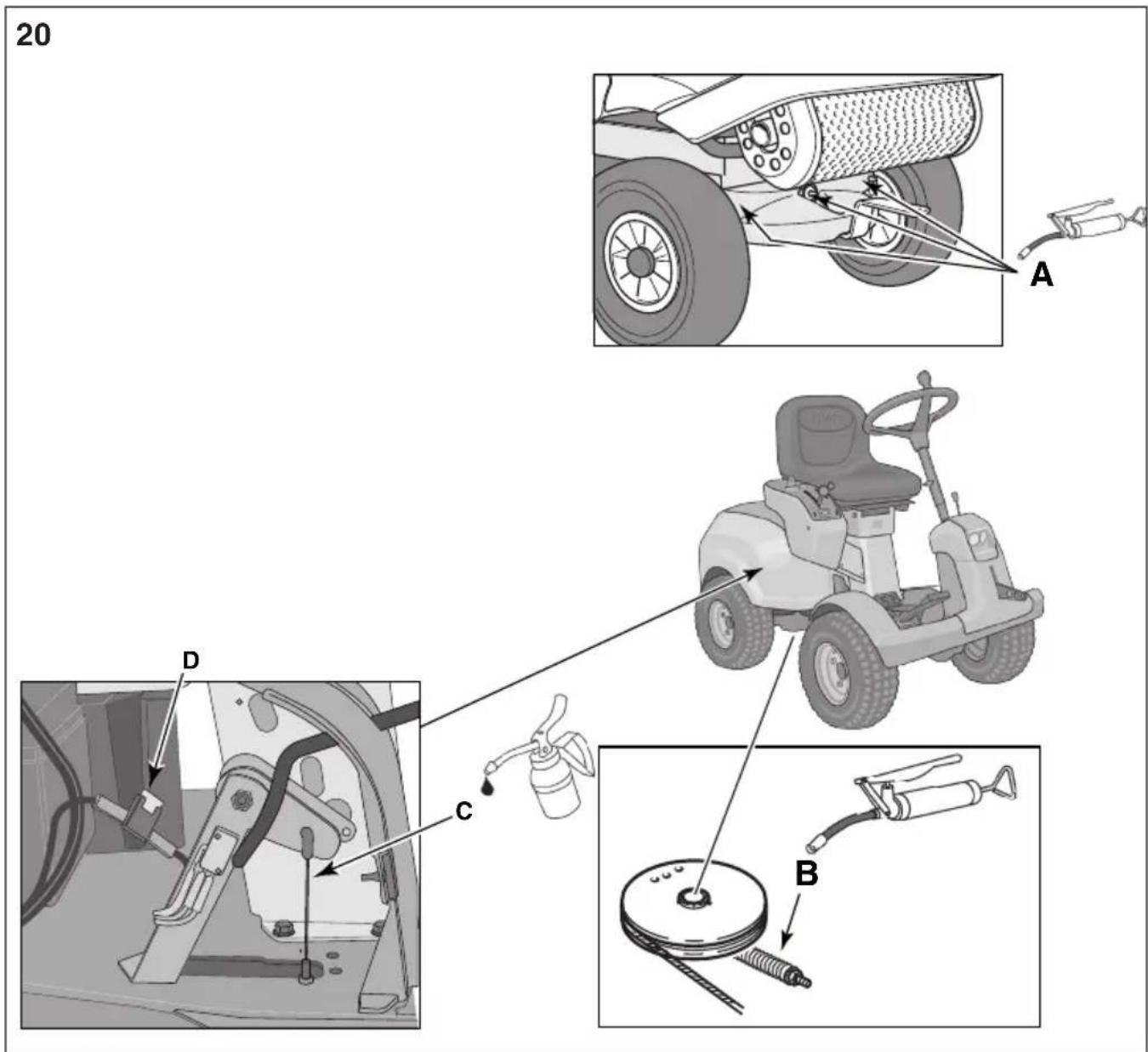
9.11 LUBRICATION (20)

For the frequency of this intervention see chapter 13.
| Object | Action Fig. | |
| Wheel bearings | 3 grease nipplesUse a grease gun filled with universal grease. | (20:A) |
| Steering spring | Use multipurpose grease (20:B) | |
| Gear cable | Lubricate the cable ends with oil when each control is activated. | (20:C) |
9.12 FUSES (20:D)
| Fault Fuse | |
| In the event of electrical faults, check/replace the fuse.If the problem persists, contact an authorized servicing centre to get the relative repairs carried out. | (20:D) |
10 ASSISTANCE AND REPAIRS
This manual provides all the necessary information to run the machine and for correct basic maintenance operations which can be performed by the user.
Any regulations and maintenance operations not described herein must be carried out by your Dealer or Authorized Service Centre, which have the necessary knowledge and equipment to ensure that the work is carried out correctly, maintaining the correct degree of safety and the original operating conditions of the machine.

Before performing any servicing operations:
a. Place the machine on a flat surface.
b. Activate the parking brake (11:B)
c. Stop the engine.
d. Remove the key from the ignition.
Authorized service workshops carry out guaranteed repairs and maintenance.
Always use genuine spare parts.

Genuine STIGA S.p.A. spare parts and accessories have been designed specifically for STIGA S.p.A. machines.
Please remember that non-genuine spare parts and accessories have not been verified or approved by STIGA S.p.A..

The use of non-genuine spare parts and accessories could adversely affect machine operation and safety.
STIGA SpA shall decline all liability in the event of injuries or damages caused by such parts.
Genuine spare parts are supplied by authorized assistance workshops and dealers.

It is advisable to send your machine once a year to an authorized service workshop for servicing, assistance and safety device inspection.
11 STORAGE
- Empty the fuel tank:
- Start the machine's engine and leave it running until it stops.
- Change the oil when the engine is still warm.
- Thoroughly clean the whole machine. It is particularly important to clean the bottom side of the cutting device assy.
- If the paintwork is damaged, touch it up to prevent rust.
- Place the machine in a covered, dry place.
For machines with electric starter:
If the storage temperature is correct, simply recharge the batter every four months.

Charge the battery before putting the machine into storage.
The battery can be seriously damaged it if is put into storage flat.
12 TERMS OF PURCHASE
The warranty covers all material and manufacturing defects.
The user must follow all the instructions provided in the accompanying documentation.
The warranty does not cover damages caused by:
- failure to become familiar with the documentation accompanying the machine,
- carelessness,
- incorrect or prohibited use or assembly,
• use of non-genuine spare parts, - use of accessories not supplied or approved by STIGA SpA.
The warranty does not cover:
- Normal wear and tear on wear parts such as the auger, etc..
• normal wear and tear - engines. Engines are covered by the warranty provided by the relative manufacturer in compliance with the specified terms and conditions.
The purchaser is protected by his own national legislation. The purchaser's rights envisaged by the national laws in his own country are not in any way restricted by this warranty.
13 MAINTENANCE SUMMARY TABLE
| Intervention Frequency | service hours/calendar months | ref. / Ref. Fig. | |
| First time Then every | |||
| MACHINE | |||
| Check all fasteners - Before each use - | |||
| Safety checks/check controls - Before each use - | |||
| Check tyre pressure - Before each use - | |||
| General cleaning and inspection - At the end of each use - | |||
| General lubrication - 50 hours and after each | wash | 9.11 | |
| Check the drive belts for wear 5 hours 50 hours | 9.7 | ||
| Check/correct steering | 5 hours | 100 hours | 9.8 |
| Battery charging | - | Before putting into storage For machines with an electric starter: carry out a top-up charge every four months. | 9.9 |
| Cleaning the battery terminals | - | When there is oxidization. | 9.9.4 |
| ENGINES/TRANSMISSION (general) | |||
| Check / Top up engine oil | - Before each use | 9.5.1 | |
| Replacing / Filling the engine oil | 5 hours | 50 hours / 12 months | 9.5.2(1) |
| Filter replacement | - 100 hours | Every two oil changes | 9.5.3 |
| Replace fuel filter | 12 months | 9.6 | |
| Replacing the spark plugs | - | 200 hours | 9.10.3 |
| Cleaning the air intake | - | 50 hours | 9.10.4 |
| Engine mod. B&S | |||
| Clean/replace the paper air filter | - | 100 hours | 9.10.1 (2) |
| Engine mod. STIGA | |||
| Clean/replace the foam air pre-filter | - | 25 hours | 9.10.2 (2) |
| Clean/replace the paper air filter | - | 100 hours | 9.10.2 (2) |
| (1) Change the oil more frequently if the engine has to work in difficult conditions or when the ambient temperature is high. | |||
| (2) Clean more frequently when operating in particularly demanding conditions or when there is debris in the air. | |||
14 TROUBLESHOOTING
| Problem Probable cause Remedy | ||
| 1. The starter motor does not turn. | Battery not charged enough. Recharge the flat battery. | |
| Battery not connected. Check the connections. | ||
| Fuse 20A blown. Replace the fuse | ||
| 2. The starter motor turns but the engine doesn't start. With the ignition key in the start position, the starter motor turns but the engine doesn't start. | Fuel cock closed. Open the fuel cock. | |
| No fuel flow. - Check the fuel level in the tank. - Check the fuel filter. | ||
| Ignition fault. - Check the spark plug cap is securely in place. - Check the spark gap and that the electrodes are clean. | ||
| 3. Difficulty in engine start-up or engine runs irregularly. | Carburettor problems. Clean or replace the air filter. | |
| 4. Drop in engine performance during cutting. | Forward speed too high in relation to the cutting height. | Reduce the forward speed and/or raise the cutting height. |
| 5. The engine stops for no apparent reason. | - Fuel tank empty. - Try to restart the engine. | Fill the fuel tank (if the problem persists, contact an authorised assistance centre). |
| 6. Uneven cutting. Check the tyre pressure. | ||
| The cutting device sharpness level is low. | Contact an authorised assistance centre. | |
| Forward speed too high in relation to the height of the grass being cut. | Reduce the forward speed and/or raise the cutting height. | |
| The cutting device assy is full of grass. | - Wait for the grass to dry. - Clean the cutting device assy. | |
| 7. Abnormal vibration during use. | - Unbalanced cutting devices. - Slackened cutting devices. - loose components. - possible damage. | Contact an authorised assistance centre for inspection, replacement or repair operations. |
| 8. With the engine running, activation of the traction pedal does not move the machine. | "Disengage transmission" lever in the disengaged position. | Engage the transmission. |
| If any of the faults listed below occurs, replace the relevant fuse (20). | ||
| 9. The engine does not start or starts and stops immediately. The battery is charged. | Fuse 20A blown. Replace fuse 20A. | |
If problems persist after the operations above have been performed, contact your dealer.

Warning! Never attempt to carry out complicated repairs without the necessary tools or technical ability. Any poorly performed interventions will automatically nullify the warranty and exonerate the manufacturer from all liability.
Indice
0 TABLA DE DATOS TÉCNICOS . . . . . . . . . . . . . . . . . . . . . . . . . . . . . . . . . . . . . . . . . . . . . . . . . . . . . . . . . . . . . . . . . . . . . . . . . . . . . . . . . . . . . . . . . VII
1 INTRODUCCIÓN. 4
1.1 ESTRUCTURA DEL MANUAL
2.2 MUDELID [Hydrostatic]
6.1 LISATARVIKUTE TÖSTMISE PEDAAL (11:A)
6.5 VEOPEDAAL [Hydrostatic] (13:E)
1.1 OPPAAN RAKENNE. 4
1.2 MERKINNÄT 4
1.3 OPPAAN SÄILYTYS 4
2 KONEEN TUNTEMINEN. 4
2.1 MALLIT [Gear]] 4
2.2 MALLIT [Hydrostatic] 4
2.3 TARKOITETTU KÄYTTÖ. 5
2.3.1 Käyttäjätyypin määritteleminen . . . . . . . . . . . . . . . . . . . . . . . . . . . . . . . . . . . . . . . . . . . . 5
2.4 VIRHEELLINEN KÄYTTÖ 5
2.5 TURVALLISUUSMERKINNÄT 5
2.5.1 Liimaetiketit (4) . . . . . . . . . . . . . . . . . . . . . . . . . . . . . . . . . . . . . . . . . . . . . . . . . . . . 5
2.6 TYYPPIKILPI 6
2.7 PÄÄASIALLISET OSAT 6
3 TURVAOHJEET 6
3.1 YLEISET SUOSITUKSET 6
3.2 ENNALTA TEHTÄVÄT TOIMENPITEET 7
3.3 KÄYTÖN AIKANA. 7
3.4 HUOLTO JA VARASTOINTI. 9
3.5 KULJETUS....10
3.6 YMPÄRISTÖNSUOJELU 11
4 VAKUUTA RUOHONLEIKKURISI ..... 11
5 ASENNUS 11
5.1 ASENNUKSEEN TARVITTAVAT OSAT (3) 11
5.2 KONEPELTI (5:A) 11
5.3 AKKU 11
5.3.1 Akun liittäminen (6) 12
5.3.2 Akun lataus. 12
5.4 ISTUIN (7) 12
5.5 OHJAUSPYÖRÄ (8) 12
5.6 VETOLAITE (9) 12
5.7 KIINTEÄT PIDIKKEET LEIKKUULAITEYKSIKÖN KIINNITTÄMISEKSI (10) ..... 12
5.8 RENGASPAINE....13
5.9 LISÄVARUSTEET....13
6 SÄÄTIMET 13
6.1 MEKAANINEN LISÄVARUSTEIDEN NOSTOPOLJIN (11:A) 13
6.2 JARRU-KYTKIN-SEISONTAJARRU-MAL.: [Gear] (11:B) 13
6.3 SEISONTAJARRUN POLJIN [Hydrostatic] (11:B) 13
6.4 SEISONTAJARRUN LUKITUSVIPU (11:C) 13
FI
SUOMI
2.2 MALLIT [Hydrostatic]
6.5 VETOPOLJIN [Hydrostatic] (13:E)
1.1 STRUCTURE DU MANUEL 4
1.2 SYMBOLES 4
1.3 CONSERVATION DU MANUEL....4
2 CONNAÎTRE LA MACHINE 4
2.1 MODÈLES [Gear] . . . . . . . . . . . . . . . . . . . . . . . . . . . . . . . . . . . . . . . . . . . . . . . 4
2.2 MODÈLES [Hydrostatic] . . . . . . . . . . . . . . . . . . . . . . . . . . . . . . . . . . . . . . . . . . . . 5
2.3 UTILISATION PRÉVUE . . . . . . . . . . . . . . . . . . . . . . . . . . . . . . . . . . . . . . . . . . . . . . . . . . . . . . . . . . . . 5
2.3.1 Définition du type d'utilisateur . . . . . . . . . . . . . . . . . . . . . . . . . . . . . . . . . . . . . . . . . . . . . . . . . . . . . . 5
2.4 UTILISATION IMPROPRE 5
2.5 SIGNAUX DE SÉCURITÉ . . . . . . . . . . . . . . . . . . . . . . . . . . . . . . . . . . . . . . . . . . . . . . . . . . . . . . . . . 5
2.5.1 Étiquettes adhésives (4) 6
2.6 ÉTIQUETTE D'IDENTIFICATION ..... 6
2.7 PRINCIPAUX COMPOSANTS (1) 6
3 NORMES DE SÉCURITÉ 6
3.1 RECOMMANDATIONS GÉNÉRALES .....7
3.2 OPÉRATIONS PRÉLIMINAIRES .....7
3.3 PENDANT L'UTILISATION 8
3.4 ENTRETIEN ET REMISAGE 10
3.5 TRANSPORT....12
3.6 PROTECTION DE L'ENVIRONNEMENT ..... 12
4 ASSURER LA TONDEUSE. 12
5 MONTAGE 12
5.1 COMPOSANTS POUR LE MONTAGE (3) 12
5.2 CAPOT MOTEUR (5:A) 12
5.3 BATTERIE 13
5.3.1 Raccordement de la batterie (6)....13
5.3.2 Charge de la batterie 13
5.4 SIÈGE (7) 13
5.5 VOLANT (8) 13
5.6 DISPOSITIF DE REMORQUAGE (9). 14
5.7 SUPPORTS FIXES POUR L'ACCROCHAGE DE L'ENSEMBLE DU DISPOSITIF DE COUPE
(10) 14
5.8 PRESSION DES PNEUS. 14
5.9 ACCESSOIRES. 14
6 COMMANDES....14
6.1 PÉDALE DE LEVAGE ACCESSOIRES MÉCANIQUE (11:A) 14
6.2 FREIN-EMBRAYAGE-FREIN DE STATIONNEMENT - mod.: [Gear] (11:B) ..... 14
6.3 PÉDALE DU FREIN DE STATIONNEMENT [Hydrostatic] (11:B) ..... 15
6.4 LEVIER DE BLOCAGE DU FREIN DE STATIONNEMENT (11:C) ..... 15
6.5 PÉDALE DE TRACTION [Hydrostatic] (13:E) 15
6.6 VOLANT (13:H). 15
6.7 ACCÉLÉRATEUR ET STARTER (si prévu) (12:D; 13:C) ..... 15
6.8 BLOC D'ALLUMAGE (12:C; 13:B) ..... 16
6.9 Levier de changement de vitesse mod.: [Gear] (12:B) 16
6.10 PRISE DE FORCE PTO (12:A; 13:A). 16
6.11 RÉGLAGE DE LA HAUTEUR DE COUPE (13:G) 16
6.12 LEVIER DE DÉBRAYAGE DE LA TRANSMISSION [Hydrostatic] (15:A) ..... 16
6.13 RÉGLAGE DU SIÈGE (15:A) 16
6.14 CAPOTMOTEUR....17
6.15 BLOCAGE TENDEUR DE COURROIE (16). 17
7 DÉMARRAGE ET CONDUITE .....17
1.1 STRUCTURE DU MANUEL
1.3 CONSERVATION DU MANUEL
9.9.3 Déposer/repose
12 CONDITIONS D'ACHAT
5.5 KORMÁNYKERÉK (8)
6.6 KORMÁNYKERÉK [Hydrostatic] (13:H)
5.6 TRAUKIMO IRENGINYS (9)
6.5 DARBINIS STABDYS-SANKABA [Hydrostatic] (13:E)
6.5 PIEDZINAS PEDALIS [Hydrostatic] (13:E)
9.1 APKOPES PROGRAMMA
6.1 PEDAAL MECHANISCHE GE-REEDSCHAPSBEVESTIGING (10:C)
7 START OG KJ∅RING....15
7.1 FORHOLDSREGLER VED BRUK 15
7.2 KOMBINERT BRUK AV TILBEH∅R 15
7.3 FYLLE BENSIN....15
7.4 KONTROLLERE OIJENIVÅET I MOTOREN (18,; 19; 19A) . . . . . . . . . . . . . . . . . . . . . . . . . . 15
7.5 SIKKERHETSKONTROLL 15
7.5.1 Generell sikkerhetskontroll 16
7.5.2 Sikkerhetskontroll av det elektriske anlegget 16
7.6 START/ARBEID 16
7.6.1 Kjøring.... 16
7.7 STOPP 16
7.8 RENGJ∅RING 17
8 BRUK AV TILBEH∅RET. 17
8.1 KLIPPEH∅YDE....17
8.2 KLIPPERÅD 17
9 VEDLIKEHOLD 17
9.1 SERVICEPROGRAM 17
9.2 KLARGJ∅RING. 17
9.3 VEDLIKEHOLDSTABELL 18
9.4 DEKKTRYKK....18
9.5 ETTERFYLLING/SKIFTE AV MOTOROLJE. 18
9.5.1 Kontroll/etterfylling (18; 19; 19A)....18
9.5.2 Skifte/etterfylling (21) 18
9.5.3 Skifte av oljefilter (hvis det finnes) 18
9.6 SKIFTE AV DRIVSTOFFILTER (18:A, 19:A; 19A:A) 19
9.7 KONTROLL AV DRIVREIM 19
9.8 STYREMEKANISME 19
9.8.1 Kontroller. 19
9.8.2 Justere slark i styringen (22) 19
9.9 BATTERI....19
9.9.1 Lading med motoren. 19
9.9.2 Lading med batterilader 19
2 BLI KJENT MED MASKINEN
3.4 VEDLIKEHOLD OG LAGRING

6.5 FREMDRIFTSPEDAL [Hydrostatic] (13:E)
6.11 KLIPPEH∅YDEINNSTILLING (13:G)
9.3 VEDLIKEHOLDSTABELL

9.5 ETTERFYLLING/SKIFTE AV MOTO- ROLJE

9.9.3 Montering/demontering
13 VEDLIKEHOLDSTABELL
2.2 MODELE [Hydrostatic]
5.9 WYPOSAŻENIE DODATKOWE
6.5 PEDAL NAPEDOWY [Hydrostatic] (13:E)
9.9.3 Demontering/montering
Batteriet sitter under motorhuven.
13 SAMMANFATTANDE TABELL FÖR UNDERHÅLL
D. Lgs. 262/2002, ANNEX VI, proc. 1 (Italy)
EN • The content and images in this User Manual were produced expressly for STIGA S.p.A. and are protected by copyright – any unauthorised reproduction or modification to the document, either partially or in full, is prohibited.
Type:
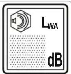
-s/n -Art.N
CE