TB 65 - Multimeter Testboy - Free user manual and instructions
Find the device manual for free TB 65 Testboy in PDF.
User questions about TB 65 Testboy
0 question about this device. Answer the ones you know or ask your own.
Ask a new question about this device
Download the instructions for your Multimeter in PDF format for free! Find your manual TB 65 - Testboy and take your electronic device back in hand. On this page are published all the documents necessary for the use of your device. TB 65 by Testboy.
USER MANUAL TB 65 Testboy
General safety notes 24
Safety notes 26
Operation 29
Switches, buttons and jacks description 31
Automatic switch-off 32
DC voltage measurement / V= 33
AC voltage measurement / V~ 33
DC current measurement / A= 34
Resistance measurement / Ω 35
Diode test 36
Continuity test 36
Temperature 37
Frequency 37
Engine speed (rotations/minute) 38
Ignition point 39
Duty cycle 39
Maintenance 40
Technical data 41
Notes
General safety notes

WARNING
Unauthorised modification and/or changes to the instrument are not permitted, for reasons of safety and approval (CE). In order to ensure safe and reliable operation using the instrument, you must always observe the safety instructions, warnings and the information contained in the section "Intended use".

WARNING
Please observe the following information before using the instrument:
- Do not operate the instrument anywhere near electrical welders, induction heaters or other electromagnetic fields.
After abrupt temperature changes, before using the instrument it must be allowed to adjust to the new ambient temperature for approx. 30 minutes, in order to stabilise the IR sensor.
Do not expose the instrument to high temperatures for a long period of time.
Avoid dusty and humid environments.
Measuring instruments and their accessories are not toys, and must be kept out of the reach of children!
In industrial facilities, the accident prevention regulations for electrical systems and equipment, established by the employer's liability insurance association, must be observed.

Please observe the five safety rules:
- Disconnect
- Ensure that the instrument cannot be switched back on again
- Ensure isolation from the power supply (check that there is no voltage at both poles)
- Earth and short-circuit
- Cover adjacent live parts
Intended use
The instrument is intended strictly for use in applications described in the operating instructions. Any other usage is considered improper and forbidden, and can result in accidents or the destruction of the instrument. Any such application will result in the immediate expiry of all guarantee and warranty claims on the part of the operator against the manufacturer.

We assume no liability for damages to property or personal injury caused by improper handling or failure to observe the safety instructions. Any warranty claim expires in such cases. An exclamation mark in a triangle indicates safety notices in the operating instructions.
Read the instructions completely before beginning the initial commissioning. This instrument is CE-approved and thus fulfils the required guidelines.
All rights reserved to change specifications without prior notice © 2014 Testboy GmbH, Germany.
Safety notes

WARNING
Further sources of danger are mechanical parts, for example, which can cause serious personal injury.
Objects are also at risk (e.g. damage to the instrument).
WARNING
An electric shock can result in death or serious personal injury, and also functional damage to objects (e.g. damage to the instrument).
Disclaimer

The warranty claim expires in cases of damages caused by failure to observe the instructions! We assume no liability for any resulting damage!
Testboy is not responsible for damage resulting from
failure to observe the instructions
Changes to the product that have not been approved by Testboy or
the use of spare parts that have not been manufactured or approved by Testboy
the use of alcohol, drugs or medication.
Accuracy of the operating instructions
These operating instructions have been compiled with due care and attention. No guarantee is given that the data, illustrations and drawings are complete or correct. All rights reserved with regard to changes, printing mistakes and errors.
Disposal
Dear Testboy customer: purchasing our product gives you the option of returning the instrument to suitable collection points for waste electrical equipment at the end of its lifespan.

The WEEE directive regulates the return and recycling of electrical appliances. Manufacturers of electrical appliances are obliged to take back and recycle all electrical appliances free of charge. Electrical devices may then no longer be disposed of through conventional waste disposal channels. Electrical appliances must be recycled and disposed of separately. All equipment subject to this directive is marked with this logo.
Disposal of used batteries

As an end user, you are legally obliged (battery law) to return all used batteries; disposal with normal domestic waste is prohibited!
Batteries containing contaminant material are labelled with adjacent symbols indicating the prohibition of disposal with normal domestic waste.
The abbreviations used for the respective heavy metals are:
Cd = Cadmium, Hg = Mercury, Pb = Lead.
You can return your used batteries free of charge to collection points in your community or anywhere where batteries are sold!
Certificate of quality
All activities and processes carried out within Testboy relating to quality are monitored permanently within the framework of a Quality Management System. Furthermore, Testboy confirms that the testing equipment and instruments used during the calibration process are subject to a permanent inspection process.
Declaration of conformity
The product conforms to the actual directives. For more detailed information go to www.testboy.de
Operation
Introduction
The Testboy® TB 65 is a multimeter for use in the automotive and workshop sector. This measuring instrument has been manufactured to the latest safety specifications, and guarantees safe and reliable operation. The multimeter is a valuable aid for all standard measurement tasks in trade and industry as well as for electronics hobbyists.
Scope of delivery
Multimeter TB 65
Safety measurement lines
Operating instructions
Safety precautions
The TB 65 left the factory with its safety features in perfect operating condition. In order to maintain this condition, the user must observe the safety notes contained in this manual.

Caution!
Only use the enclosed safety test leads or equivalent test leads that meet the same measurement category.
In order to avoid risk of electric shock, you must observe the specified precautions when working with voltages greater than 120V (60 V) DC or 50 V (25 V) eff AC. These values represent the limits of safe-to-touch voltages in accordance with DIN VDE. (Values given in brackets apply to medical or agricultural areas, for example)
Before taking each measurement, ensure that the test lead and the test instrument are in perfect working order
The test leads and test probes must only be handled using the grips provided. Avoid touching the test probes under any circumstances.

The test instrument must only be used for the measuring ranges specified.
According to the standard EN 61010-1, the following measurement categories are defined:
Measurement category CAT II
Measurements on circuits that are directly electrically connected to the network, via plugs in the home, office and laboratory.
Measurement category CAT III
Measurements on building installations: fixed consumer units, distributor connection, equipment fitted permanently to the distributor
Measurement category CAT IV
Measurements at the source of the low voltage installation: meters, primary surge protection, mains connection.
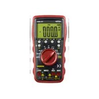
Switches, buttons and jacks description
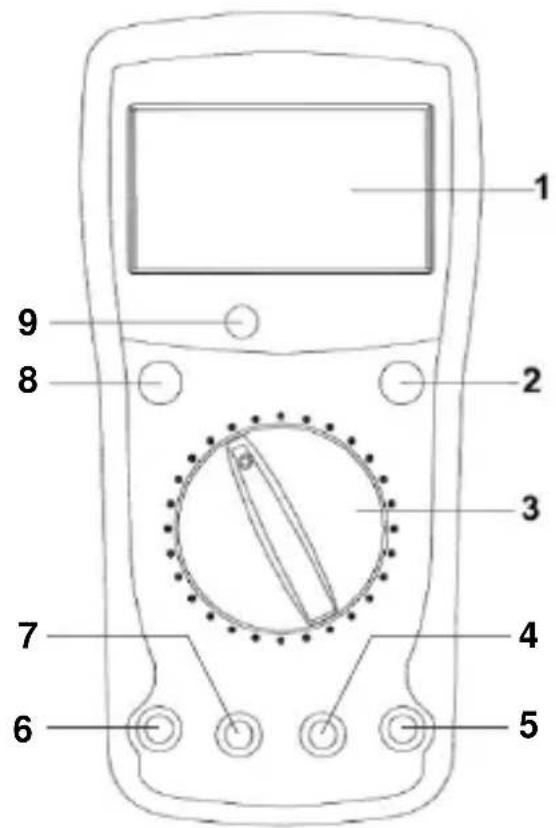
(1) LC display
(2) Measurement value save button "HOLD"
By activating the button, the actual measurement value is saved.
(3) Measuring function selector switch
Use the rotary selector switch to select the various basic measurement modes.
(4) Earth jack
Black test lead for all types of signals supported by the instrument.
(5) Input jack V/Ω
Red test lead for all types of signals supported by the instrument.
(6) 20 A jack (left)
The 20 A jack must be used for current measurements above 200mA .
(7) mA jack
For current measurements up to 200mA .
(8) ON/OFF switch
The instrument is turned on and off using a "POWER" pushbutton switch.
(9) Light sensor (
Automatic switch-off
After 15 minutes in the switched on condition, the instrument automatically reverts to the sleep mode, in order to save battery capacity. Hereby, the display is switched off and only very little energy is consumed.
In order to revert to normal operating mode, press the button "POWER" twice.
Automatic background lighting
For measuring in a dark environment, the background lighting of the display is automatically switched on by the light sensor (9).
As soon as reverting to a brighter area, the lighting is switched off.
Saving function (HOLD)
At difficult measurement positions, the display cannot perhaps be read correctly.
By pressing the button "HOLD", the actual measurement value is frozen and can then be read in comfort.
By pressing again, you revert to normal measuring mode.
DC voltage measurement / V=
Set the appropriate range using the selector switch. Connect the black test lead to the "COM" jack and the red test lead to the "V/Ω" jack.
Connect test leads to the test specimen. Read off measurement result from the display. The voltage polarity is also displayed.
DC voltage
| Measuring range | Resolution | Accuracy |
| 200 mV | 0.1 mV | ±0.5 % of the measurement range + 5 Digit |
| 2 V | 1 mV | |
| 20 V | 10 mV | |
| 120 V | 100 mV |
- Input resistance: 10 M
- Overvoltage protection: 250 Vrms
AC voltage measurement / V~
Set the appropriate range using the selector switch. Connect the black test lead to the "COM" jack and the red test lead to the "V/Ω" jack. Connect test leads to the test specimen. Read off measurement result from the display.
AC voltage
| Measuring range | Resolution | Accuracy |
| 50 V | 100 mV | ±1.2 % of the measurement range + 5 Digit |
- Input resistance: 4.5 M .
- Overvoltage protection: 250 Vrms
- Frequency range: 40-400 Hz
DC current measurement / A=
Set the appropriate range using the selector switch. Connect the black test lead to the "COM" jack and the red test lead to the "mA" and "20A" jack measurement line to the test specimen. Read off measurement result from the display. The current direction is indicated by the sign.

You must use the "20 A" jack when measuring currents above 200 mA!
Direct current
| Measuring range | Resolution | Accuracy |
| 20 mA | 10 μA | ±1.8 % of the measurement range + 3 Digit |
| 200 mA | 100 μA | |
| 20 A* | 10 mA | ±3.0 % of the measurement range + 5 Digit |
Overload protection:
- The mA range is safeguarded by a 200 mA self-resetting fuse.
- In the 20 A range observe the maximum duty cycles!

- Following measurement, which should take a max. 10 seconds, allow the instrument to cool down for 15 minutes to protect against overheating.
Resistance measurement /
Set the appropriate range using the selector switch. Connect the black test lead to the "COM" jack and the red test lead to the "V/Ω" jack. Connect test leads to the test specimen. Read off measurement result from the display.
| Measuring range | Resolution | Accuracy |
| 200 Ω | 0.1 Ω | ±1 % + 5 Digit |
| 2 KΩ | 1 Ω | |
| 20 KΩ | 10 Ω | |
| 200 KΩ | 100 Ω | |
| 2 MΩ | 1 KΩ | |
| 200 MΩ | 100 KΩ | ± (Measurement value-10) × 5.0 % + 5 Digit |
- Overvoltage protection: 250 V RMS

In the 200 range, the resistance of the measurement lines can be compensated by short-circuiting the test lines before the measurement and subtracting the value indicated from the later measurement value.
Diode test
Set the selector switch to " l /“. Connect the black test lead to the “COM” jack and the red test lead to the “V/Ω” jack. Connect test leads to the test specimen. Red test lead = anode, black test lead = cathode. The forward voltage drop is displayed.
Measuring range

Resolution
1mV
Display
Forward voltage
- Supply current: approx. 25 A
- Overvoltage protection: 250 V RMS
Continuity test
Set to "using the selector switch. Connect the black test lead to the "COM" jack and the red test lead to the V/Ω/TEMP/CAP jack. Connect test leads to the test circuit. A signal is emitted if a resistance under 45 is measured.

Important: Ensure isolation from the power supply and discharge capacitors in the circuit to be measured.
Measuring range

Function
The integrated buzzer signals continuity less than 45
- Measurement circuit voltage: 3 V
Temperature
Set the selector switch to "°C". Connect a Type-K temperature sensor (nickel-chrome / nickel) to the jacks "mA" (t+) and "V/Ω" (t- ". Touch the object to test with the measurement probe. Read off measurement result from the display.
| Measuring range | Resolution | Accuracy |
| -40 to 0 °C | 1 °C | ±2 % + 8 Digit |
| 0 to 400 °C | ±2 % + 3 Digit | |
| 400 to 1000 °C | ±1 % + 3 Digit |
Frequency
Set the selector switch to "Hz". Connect the black test lead to the "COM" jack and the red test lead to the "V/Ω" jack. Connect test leads to the test circuit. Read off measurement result from the display.
| Measuring range | Resolution | Accuracy |
| 20 kHz | 0.001 kHz | ±2 % + 5 Digit |
| 200 kHz | 0.1 kHz |
- Sensitivity: 5 Vrms
- Max. input voltage 250 Vrms
Engine speed (rotations/minute)
Set the type of engine using the selector switch. Connect the black test lead to the "COM" jack and the red test lead to the "V/Ω" jack. The measurement result is indicated on the display times 10 rpm.
Connect the black test lead to the vehicle earth and the red test lead to the negative connection of the ignition coil.
| Cylinder | Measuring range | Resolution | Accuracy |
| DIS* | |||
| 3CYL | 500 – 10.000 min-1 | 10 min-1 | ±3 % + 5 Digit |
| 4CYL | |||
| 5CYL | |||
| 6CYL | |||
| 8CYL |
- Sensitivity: 5 Vrms
-
Max. input voltage 250 Vrms
-
With a ignition system without a distributor (DIS), connect the red test lead to the speed signal line of the controller for the ignition system iaw. the service manual from the vehicle manufacturer.
Ignition point
Set the selector switch for type of engine to the domain "Dwell 4". Connect the black test lead to the "COM" jack and the red test lead to the "V/Ω" jack.
Connect the black test lead to the vehicle earth and the red test lead to the negative connection of the ignition coil.
| Cylinder | Measuring range | Resolution | Accuracy |
| 3CYL | 0 - 120° | 0.1° | ±3 % + 5 Digit |
| 4CYL | 0 - 90° | ||
| 5CYL | 0 - 72° | ||
| 6CYL | 0 - 60° | ||
| 8CYL | 0 - 45° |
Duty cycle
Set the selector switch to "Duty %. Connect the black test lead to the "COM" jack and the red test lead to the "V/Ω" jack. Connect test leads to the test circuit. Read off measurement result from the display.
| Measuring range | Resolution | Accuracy |
| 0 – 100 % | 0.1 % | ±3 % + 5 Digit |
- Sensitivity: 5 Vrms
- Max. input voltage 250 Vrms
Maintenance
The instrument does not require special maintenance when used as specified in these operating instructions.
Cleaning
Use a damp cloth and mild household detergent to clean the instrument should it become soiled through daily use. Never use aggressive cleaning agents or solvents to clean the instrument.
Replacing the battery
Change the batteries when the battery symbol appears on the display. Remove the test leads from the instrument before changing the batteries!
Remove the three screws on the rear, open the battery compartment and remove the discharged battery. Insert the new battery (1 × 9 V block 6F22). Replace battery compartment and screw tight.

Only use the batteries specified!
Batteries must not be disposed of with normal domestic waste! Observe the statutory regulations pertaining to disposal!
Technical data
| DC V measurement | 0...120 V @10 MΩ Accuracy ±0.5% +5 digits |
| AC V measurement | 0...50 V @4.5 MΩ Accuracy ±1.2% +5 digits |
| DC measurement | 0...200 mA Accuracy ±1.8% +3 digits 0.02...20 A Accuracy ±3% +5 digits |
| Resistance measurement | 0...2 MΩ Accuracy ±1% +5 Digits 2...200 MΩ Accuracy ± (measurement value-10) * 5% +5 digits |
| Diode test | Supply current approx. 25 mA |
| Continuity test | 0...45 Ω |
| Temperature measurement | -40...0 °C Accuracy ±2% +8 digits 0...400 °C Accuracy ±2% +3 digits 400...1000 °C Accuracy ±1% +3 digits |
| Speed measurement | 500...10000 rpm Accuracy ±3% +5 digits |
| Ignition point measurement | 0...120° Accuracy ±3% +5 digits |
| Duty cycle measurement | 0...100% Accuracy ±3% +5 digits |
| Frequency measurement | 0...200 kHz Accuracy ±2% +5 digits |
| Fuses | F 200 mA resets automatically (maintenance-free) and F 10 A |
| Max. operating height | 2000 m above MSL |
| Height of figures | 26 mm |
| Display | 3 1⁄2 digits (max. 1999) |
| Polarity indicator | Automatic |
| Over-range indicator | “1” is displayed |
| Sampling rate | approx. 0.4 s. |
| Battery status | Battery icon is displayed |
| Power supply | 1 × 9-V block battery |
| Operating temperature | 0 °C to 40 °C |
| Storage temperature | -10 °C to 50 °C |
| Dimensions | 180 × 84 × 55 mm |
| Weight | 335 g incl. battery |
Table des matieres
Consignes 44
(1) LC-display
(2) Minnesknapp for matvarden "HOLD"
Hactoza HctpyKnno no noIb3OBaHnIO COCTaBJeHa C ocObo TtatehHOCTbIO. Pn 3TOM n3rTOBNTeJIb He HecET OTBeTCTBeHHOCtB 3a npaBnIbHOCTb I NOJHO TY DaHHbIX, pncyHKOB n YepTeKei. Bo3MOxHbI n3MeHeHnA, OpeaTKn N HeTOUHOCTN.
YTNIN3aun
Ybaxaemblnokynatelnb n3deJnra Testboy! Ctab o6naTeIeHnHaWeRo n3dEJIy, Bbl NOJyUHnB03MOXHOCTb cdaTb erO N0 OKOHuaHnCpOKa clyx6bl Ha cneuJaHbI pyHKT c6opaOTcJyXHBweJ əJIeKTPoTeXHnKn.

ДиректINA WEEE pergynpyet BO3BpaT n yTNIN3aCnIO əJIeKtpnueckoro obopydoBaHnI. Ipon3BOiTeI IN əJIeKtpnueckoro obopydoBaHnI o6ra3aHbI 6ecnIaTHO 3a6npaTb n yTNIN3nPoBaTb BCE əJIeKtpnueckne np6obpbl. əJIeKtpoPn6Opbl 6OJbIe HeIb3a YTNIN3nPoBaTb NO O6bUHbIM KaHaJAM yTNIN3aCIn OTxODOB. əJIeKtpoPn6Opbl DoJXHbI nepepaTaBtBaTbcr n yTNIN3nPoBaTbC8 OTdEJIbHO. BcE obopynDaHnE, nonaJaOnuee POn DaHNHyU DipeKTHBy, NOMEueHo 3Tm IIOROTINOM.
YTNIN3aunnncnoB3OBaHHbIX 3JeMeHTOB NITAHN

I0 3aKoHy (ob yTuHn3aun 3JeMeHTOB nHTaHn) Bbl KaK KOHeuHbI NOJIb3OBAteJIb 6oJ3aHbI BO3BpaUaTb BCE IcNoJIb3OBAHHbIe 6aTapeN i aKKyMylrTOpbl; yTuHn3aun C 6bITOBbIM MyCopom BocnPeeTaetc!
A B T O M A T N U C E C K O E O T K J I H O Y E H N E
Iocne 15 MInHyT Bo BkJIIOueHHom COCTOaHn IprbOp aBTOMaTHueCKn
IepexoJNT B "CpAun" pExHM, UTo6bI COxpaHHTb 3aprAd
aKKymyJATOPHO BaTapeN. Ppi 3Tom dncPJIeN OTKJIIOUaETcR
I Notpe6JIaET NlMb OChb He3HaHTeJIbHOe KOJIuYeCTBO 3HeprHn.
HaXmTe DByKpaTHO KHOJKy «POwER», UTo6bI BEpyTbcra
0bpaTHO K HopMaJIbHOMy pExIMy pa6oTbl.
ABTOMATNuecka fOHOBaI NOcBETka
KpaTHOCTb MaHnPyJauCNI
YCTaHOBnTB NepeKJIouaTeIb B NoLoJKeHne «Duty %». CoeINHnTb I3MePnTeIbHbI KOHcEBoI npoBOd YepHOTo c THe3dOM «COM», a I3MePnTeIbHbI KOHcEBoI npoBOd KpaCHOTo c TBeTa C THe3dOM «V/Ω». POnCoEHNtB I3MePnTeIbHbIe KOHcEBBie npoBOda K cenII npOBepKn. CHTaTB pe3yIbTat I3MepeHnHa dInCpJIee.
Диапа3OH n3Меренья
0-100%
Pa3peшенe
0,1 %
ToUHOCTb
±3% + 5 pa3рядов
- YyBCTBNTeIbHocTb: 5 B (cpeiHeKBaIpaTnUHa BeJIuHa)
- MaKc. BxOdHoe HapRjXeHne 250 B (cpeDHeKBaIpaTnUHa BeJIuYHa)
TexHnueckoe o6cIyXnBaHne
Pn 3Kcnpyaatau np6op corgaCHO nHCTpykunno no noIb3OBAHNO He Tpe6yeT oc6oro texnueckoro o6cnyxnbHna.
OuNTka
Ecn np6bop B npoecce ekeDHeBHO npmeHn 3aqr3HTcT,TO np6bop MOxHO ONUCTNb C NOMOUsbIO BnaXHOJ CaIΦeTKN H60JIbWoRO KOINueCTBa Cna6OeJCTByUoSeIro 6bITOBOrO cpeiCTBa DnA ONUCTKn. HnkOrDa He npimeHnTe dIy ONUCTKn CNJIbHOJeCTByUoUee CpeDCTBO dIy ONUCTKn IIn PaCTBOPNTeIb.
3aMeHa 6aTapen
3aMeHa 6aTapeN IOTpe6yeTcB TOM Clyuae, KOrda Ha DnCnJIee
IPOABNTcCIMBOJ 6aTapeN epeD 3aMeHOJ 6aTapeN
Heo6XoDNMO OTcoeHNITb N3MePHTeNbHbIe KOHcEBBie npOBoDa!
BbIKpyTITb paCNOJIOKeHHbIe Ha o6paTHOJ CTOPOHe TpN BnHTa,
OTKpbITb KpbIShKy 6aTapeINHOrO OTcKa N n3BLeUb pa3PraJxEHHyIO
6aTapeIO. BCTaBNtB HOyIO 6aTapeIO (1 x 9 B - TnI 6F22). 3aKpbITb
KpbIShKy 6aTapeINHOrO OTcKa N 3aKpeINTBnHTaMNI.

Приименяп Te Tolyko 6aTapeo yka3aHnO r Tnna! He yTuJIIn3npyTe 6aTapeu c 6bITOBbIM Mycopom! Co6JIIOdaIte yCTaHOBJIeHHbIe 3aKOHOM ppeDnIcAHnЯ no yTuJIIn3aUu!
TexHnueckne xapakTepncnKn
Stands For Quality Since 1963