DW614 - Router DEWALT - Free user manual and instructions
Find the device manual for free DW614 DEWALT in PDF.
| Brand | DEWALT |
| Model | DW614 |
| Product type | Router (plunge router) |
| Rated voltage | 230 V |
| Input power | 750 W |
| Output power | 500 W |
| No-load speed | 24,000 min⁻¹ |
| Base | 2 columns |
| Plunge depth | 35 mm |
| Turret stop | 3 positions with graduated scale |
| Collet chuck | 8 mm (UK: 1/4") |
| Max cutter diameter | 30 mm |
| Weight | 2.8 kg |
| Sound pressure level (LpA) | 83 dB(A) |
| Sound power level (LwA) | 92 dB(A) |
| Vibration emission (ah) | 5.3 m/s² |
| Vibration uncertainty (K) | 1.5 m/s² |
| Double insulation | Yes (conforms to EN60745) |
| Recommended fuse | 10 A |
| Package contents | 1 router, 1 parallel guide, 1 collet 8 mm, 1 open-end wrench 13/17 mm, 1 copy sleeve 17 mm, 1 extraction nozzle, 1 manual |
| Maintenance | Clean with dry air, no additional lubrication |
| Safety | Use a 30 mA residual current device, wear safety glasses and a dust mask |
Frequently Asked Questions - DW614 DEWALT
User questions about DW614 DEWALT
0 question about this device. Answer the ones you know or ask your own.
Ask a new question about this device
Download the instructions for your Router in PDF format for free! Find your manual DW614 - DEWALT and take your electronic device back in hand. On this page are published all the documents necessary for the use of your device. DW614 by DEWALT.
USER MANUAL DW614 DEWALT
English (original instructions) 19
EAAyniKa (eTAPpaaon aTOIc npwrotuneo odnyies) 95
A
B
C
D
E
F
G
H
HANDOVERFRAESER DW614, DW615
Tillykke!
DYBDE.JUSTERING MED OVERFRAESEREN I OMVENDT STILLING
OBERFRÄSE DW614, DW615
You have chosen a DEWALT tool. Years of experience, thorough product development and innovation make DEWALT one of the most reliable partners for professional power tool users.
Technical data
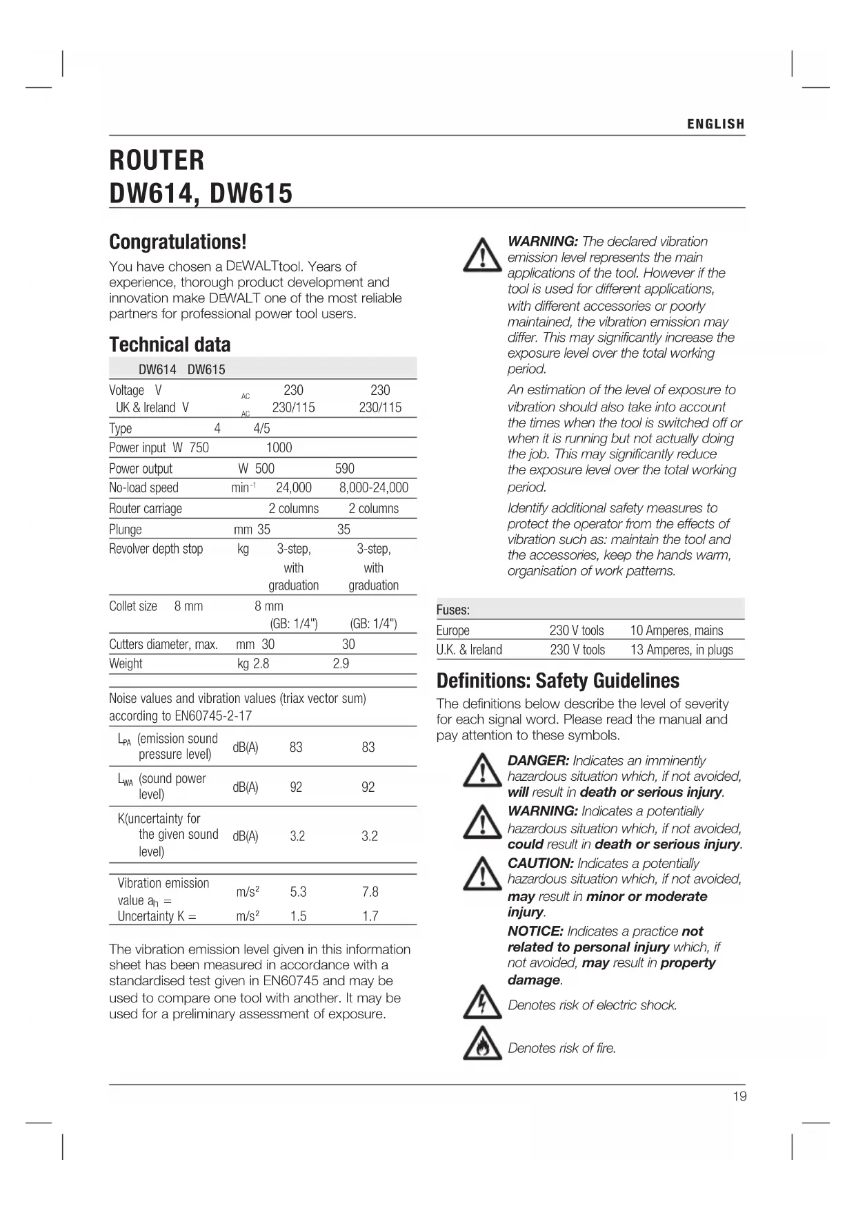
| DW614 DW615 | |||
| Voltage V | AC | 230 | 230 |
| UK & Ireland V | AG | 230/115 | 230/115 |
| Type | 4 | 4/5 | |
| Power input W 750 | 1000 | ||
| Power output | W 500 | 590 | |
| No-load speed | min-1 | 24,000 | 8,000-24,000 |
| Router carriage | 2 columns | 2 columns | |
| Plunge | mm 35 | 35 | |
| Revolver depth stop | kg | 3-step, with graduation | 3-step, with graduation |
| Collet size 8 mm | 8 mm (GB: 1/4") | (GB: 1/4") | |
| Cutters diameter, max. | mm 30 | 30 | |
| Weight | kg 2.8 | 2.9 | |
Noise values and vibration values (triax vector sum) according to EN60745-2-17
| LPA (emission sound pressure level) | dB(A) | 83 | 83 |
| LWA (sound power level) | dB(A) | 92 | 92 |
| K(uncertainty for the given sound level) | dB(A) | 3.2 | 3.2 |
| Vibration emission value an = Uncertainty K = | m/s2 | 5.3 | 7.8 |
| m/s2 | 1.5 | 1.7 |
The vibration emission level given in this information sheet has been measured in accordance with a standardised test given in EN60745 and may be used to compare one tool with another. It may be used for a preliminary assessment of exposure.

WARNING: The declared vibration emission level represents the main applications of the tool. However if the tool is used for different applications, with different accessories or poorly maintained, the vibration emission may cliffer. This may significantly increase the exposure level over the total working period.
An estimation of the level of exposure to vibration should also take into account the times when the tool is switched off or when it is running but not actually doing the job. This may significantly reduce the exposure level over the total working period.
Identify additional safety measures to protect the operator from the effects of vibration such as: maintain the tool and the accessories, keep the hands warm, organisation of work patterns.
| Fuses: | ||
| Europe | 230 V tools | 10 Amperes, mains |
| U.K. & Ireland | 230 V tools | 13 Amperes, in plugs |
Definitions: Safety Guidelines
The definitions below describe the level of severity for each signal word. Please read the manual and pay attention to these symbols.

DANGER: Indicates an imminently hazardous situation which, if not avoided, will result in death or serious injury.

WARNING: Indicates a potentially hazardous situation which, if not avoided, could result in death or serious injury.

CAUTION: Indicates a potentially hazardous situation which, if not avoided, may result in minor or moderate injury.
NOTICE: Indicates a practice not related to personal injury which, if not avoided, may result in property damage.

Denotes risk of electric shock.

Denotes risk of fire.
ENGLISH
EC-Declaration of Conformity MACHINERY DIRECTIVE

ROUTER DW614, DW615
DEWALT declares that these products described under Technical Data are in compliance with: 2006/42/EC, EN60745-1:2009+A11:2010, EN60745-2-17:2010.
These products also comply with Directive 2004/108/EC (until 19.04.2016), 2014/30/EU (from 20.04.2016) and 2011/65/EU. For more information, please contact DEWALT at the following address or refer to the back of the manual.
The undersigned is responsible for compilation of the technical file and makes this declaration on behalf of DEWALT.

Markus Rompel
Director Engineering
D-65510, Idstein, Germany
18.06.2015

MNG: To reduce the risk of injury, read the instruction manual.
General Power Tool SafetyWarnings

WARNING! Read all safety warnings and instructions Failure to follow the warnings and instructions may result in electric shock, fire and/or serious injury.
SAVE ALL WARNING AND INSTRUCTIONS FOR FUTURE REFERENCE
The term "power tool" in the warnings refers to your mains-operated (corded) power tool or battery-operated (cordless) power tool.
1) WORK AREA SAFETY
a) Keep work area clean and well lit. Cluttered or dark areas invite accidents.
b) Do not operate power tools in explosive atmospheres, such as in the presence of flammable liquids, gases or dust. Power tools create sparks which may ignite the dust or fumes.
c) Keep children and bystanders away while operating a power tool. Distractions can cause you to lose control.
2) ELECTRICAL SAFETY
a) Power tool plugs must match the outlet. Never modify the plug in any way. Do not use any adapter plugs with earthed (grounded) power tools. Unmodified plugs and matching outlets will reduce risk of electric shock.
b) Avoid body contact with earthed or grounded surfaces such as pipes, radiators, ranges and refrigerators. There is an increased risk of electric shock if your body is earthed or grounded.
c) Do not expose power tools to rain or wet conditions. Water entering a power tool will increase the risk of electric shock.
d) Do not abuse the cord. Never use the cord for carrying, pulling or unplugging the power tool. Keep cord away from heat, oil, sharp edges or moving parts. Damaged or entangled cords increase the risk of electric shock.
e) When operating a power tool outdoors, use an extension cord suitable for outdoor use. Use of a cord suitable for outdoor use reduces the risk of electric shock.
If operating a power tool in a damp location is unavoidable, use a residual current device (RCD) protected supply. Use of an RCD reduces the risk of electric shock.
3) PERSONAL SAFETY
a) Stay alert, watch what you are doing and use common sense when operating a power tool. Do not use a power tool while you are tired or under the influence of drugs, alcohol or medication. A moment of inattention while operating power tools may result in serious personal injury.
b) Use personal protective equipment. Always wear eye protection. Protective equipment such as dust mask, non-skid safety shoes, hard hat, or hearing protection used for appropriate conditions will reduce personal injuries.
c) Prevent unintentional starting. Ensure the switch is in the off position before connecting to power source and/or battery pack, picking up or carrying the tool. Carrying power tools with your finger on the switch or energising power tools that have the switch on invites accidents.
d) Remove any adjusting key or wrench before turning the power tool on. A wrench or a key left attached to a rotating part of the power tool may result in personal injury.
e) Do not overreach. Keep proper footing and balance at all times. This enables better control of the power tool in unexpected situations.
f) Dress properly. Do not wear loose clothing or jewellery. Keep your hair, clothing and gloves away from moving parts. Loose clothes, jewellery or long hair can be caught in moving parts.
g) If devices are provided for the connection of dust extraction and collection facilities, ensure these are connected and properly used. Use of dust collection can reduce dust-related hazards.
4) POWER TOOL USE AND CARE
a) Do not force the power tool. Use the correct power tool for your application. The correct power tool will do the job better and safer at the rate for which it was designed.
b) Do not use the power tool if the switch does not turn it on and off. Any power tool that cannot be controlled with the switch is dangerous and must be repaired.
c) Disconnect the plug from the power source and/or the battery pack from the power tool before making any adjustments, changing accessories, or storing power tools. Such preventive safety measures reduce the risk of starting the power tool accidentally.
d) Store idle power tools out of the reach of children and do not allow persons unfamiliar with the power tool or these instructions to operate the power tool. Power tools are dangerous in the hands of untrained users.
e) Maintain power tools. Check for misalignment or binding of moving parts, breakage of parts and any other condition that may affect the power tool's operation. If damaged, have the power tool repaired before use. Many accidents are caused by poorly maintained power tools.
f) Keep cutting tools sharp and clean.
Property maintained cutting tools with sharp cutting edges are less likely to bind and are easier to control.
g) Use the power tool, accessories and tool bits etc., in accordance with these instructions taking into account the working conditions and the work to be performed. Use of the power tool for operations different from those intended could result in a hazardous situation.
5) SERVICE
a) Have your power tool serviced by a qualified repair person using only identical replacement parts. This will ensure that the safety of the power tool is maintained.
Additional Specific Safety Rules for Routers
- Hold power tool by insulated gripping surfaces, because the cutter may contact its own cord. Cutting a "live" wire may make exposed metal parts of the power tool "live" and shock the operator.
- Use clamps or another practical way to secure and support the workpiece to a stable platform. Holding the work by your hand or agains the body leaves is unstable and may lead to loss of control.
Additional Specific Safety Rules for Cutters
Always use cutters with a shank diameter corresponding to the size of the collet installed in your tool.
Always use cutters suitable for a speed of 30.000min^-1 and marked accordingly.

WARNING: Never use cutters with a diameter exceeding the maximum diameter indicated in the technical data.

G: We recommend the use of a residual current device with a residual current rating of 30mA or less.
Residual Risks
In spite of the application of the relevant safety regulations and the implementation of safety devices, certain residual risks cannot be avoided. These are:
Impairment of hearing
- Risk of personal injury due flying particles.
- Risk of burns due to accessories becoming hot during operation.
- Risk of personal injury due to prolonged use.
Markings on Tool
The following pictograms are shown on the tool:

Read instruction manual before use.
DATE CODE POSITION (FIG. A)
The Date Code (21), which also includes the year of manufacture, is printed into the housing.
ENGLISH
Example:
2016 XX XX
Year of Manufacture
Package Contents
The package contains:
1 Router
1 Parallel fence with guide rods
1 Collet 8 mm (GB: 1/4")
1 Wrench # 13/17
1 Guide bush 17 mm o
1 Dust extraction channel
1 Instruction manual
- Check for damage to the tool, parts or accessories which may have occurred during transport.
Take the time to thoroughly read and understand this manual prior to operation.
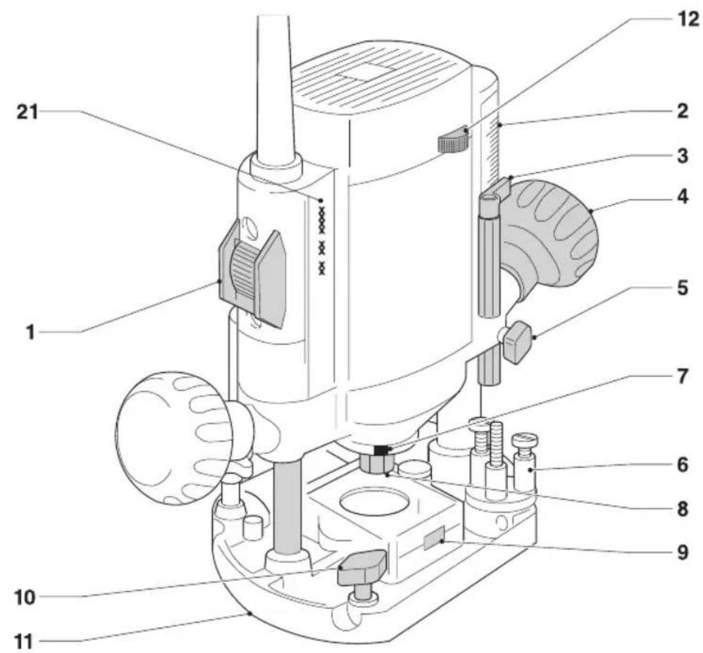
Description (fig. A)

WARNING: Never modify the power tool or any part of it. Damage or personal injury could result.
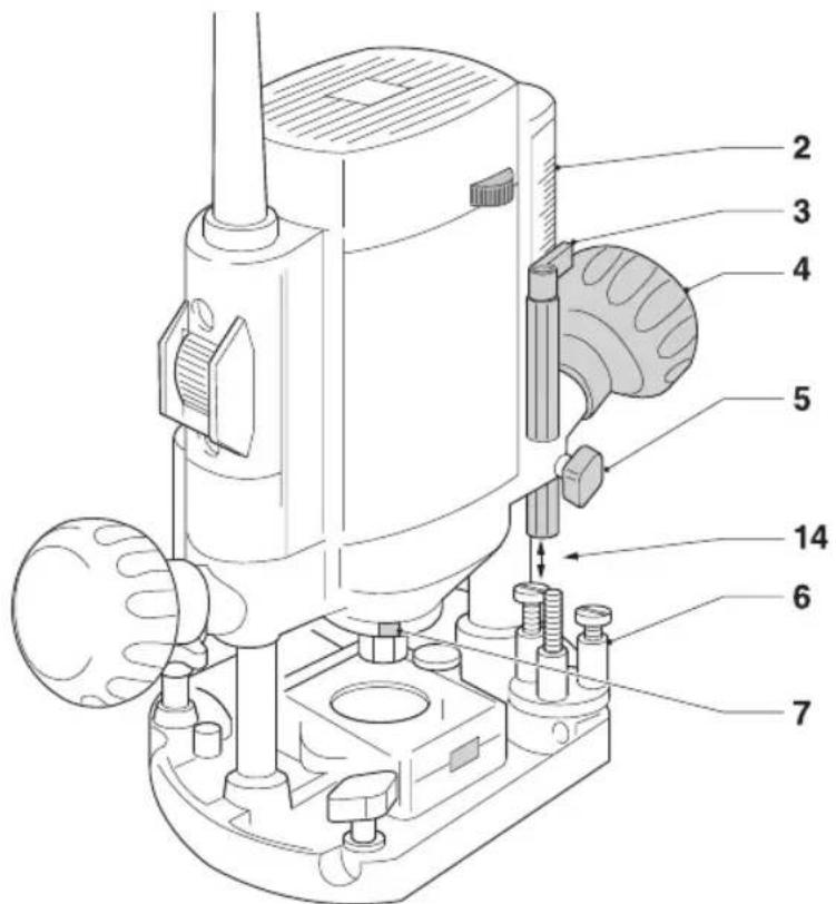
- On/off switch
- Routing depth graduation
- Depth stop
- Plunge limiter
- Depth stop locking bolt
- Revolver depth stop
- Spindle lock
- Collet nut
- Dust extractor
- Parallel fence locking bolt
- Router base
- Speed control dial (DW615)
INTENDED USE
Your DEWALT high performance router DW614, DW615 has been designed for professional heavy duty routing applications.
DO NOT use under wet conditions or in presence of flammable liquids or gases.
This router is a professional power tool.
DO NOT let children come into contact with the tool. Supervision is required when inexperienced operators use this tool.
- Young children and the infirm. This appliance is not intended for use by young children or infirm persons without supervision.
- This product is not intended for use by persons (including children) suffering from diminished physical, sensory or mental abilities; lack of experience, knowledge or skills unless they are supervised by a person responsible for their safety. Children should never be left alone with this product.
Electrical Safety
The electric motor has been designed for one voltage only. Always check that the power supply corresponds to the voltage on the rating plate.

Your DWALT tool is double insulated in accordance with EN60745; therefore no earth wire is required.

WARNING: 115 V units have to be operated via a fail-safe isolating transformer with an earth screen between the primary and secondary winding.
If the supply cord is damaged, it must be replaced by a specially prepared cord available through the DEWALT service organisation.
Mains Plug Replacement (U.K. & Ireland Only)
If a new mains plug needs to be fitted:
- Safely dispose of the old plug.
- Connect the brown lead to the live terminal in the plug.
- Connect the blue lead to the neutral terminal.

WARNING: No connection is to be made to the earth terminal.
Follow the fitting instructions supplied with good quality plugs. Recommended fuse: 13 A.
Using an Extension Cable
If an extension cable is required, use an approved 3-core extension cable suitable for the power input of this tool (see Technical Data). The minimum conductor size is 1.5mm^2 ; the maximum length is 30m .
When using a cable reel, always unwind the cable completely.
ASSEMBLY AND ADJUSTMENTS

JG: To reduce the risk of injury, turn unit off and disconnect machine from power source before installing and removing accessories, before adjusting or changing setups or when making repairs. Be sure the trigger switch is in the OFF position. An accidental start-up can cause injury.
Cutters
The tooling can be used with the complete range of commercial cutters (e.g: straight, rebate, profile cutter, slotter cutter or grooved knife) with the following technical data:
- Shank diameter 6 mm-8 mm
- Cutter speed of min. 30,000/min

diameter to use:
-
Straight, rabbit or profile cutter with a max shank diameter of 8 mm, a max diameter of 36 mm and a max cutting depth of 10 mm;
-
Slotter cutter with a max shank diameter of 8 mm and a max diameter 25 mm;
Grooved knife with a max shank diameter of 8 mm, a max diameter of 40 mm and a cutting width of 4 mm.
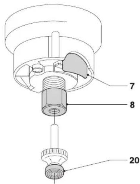
Inserting and Removing a Cutter (fig. B)
- Press and hold down the spindle lock (7).
- Using the 17mm wrench, loosen the collet nut (8) a few turns and insert a cutter.
- Tighten the collet nut and release the spindle lock.

WARNING: Never tighten the collet nut without a cutter in the collet.
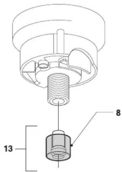
Replacing the Collet Assembly (fig. C)
Your router is supplied with a 8 mm (GB: 1/4'' ) collet fitted to the tool. Two other precision collets are also available to suit the cutter used. The collet and the collet nut are inseparable.
- Loosen the collet nut (8) completely.
- Remove the collet assembly (13).
- Fit a new assembly and tighten the collet nut (8).
Setting the Electronic Speed Control Dial (fig. A)
DW615
The speed is infinitely variable from 8,000 to 24,000min^-1 using the electronic speed control dial (12).
- Turn the electronic speed control dial to the required level.
- Generally, use the low setting for large diameter cutters and the high setting for small diameter cutters. The correct setting, however, is a matter of experience.
Adjusting the Depth of Cut (fig. D) DEPTH ADJUSTMENT USING THE GRADUATION AND REVOLVER DEPTH STOP
- Loosen the depth stop locking bolt (5).
2 Unlock the plunge limiter (4) by turning it counterclockwise. - Lower the router carriage until the cutter is in contact with the workpiece.
- Tighten the plunge limiter (4).
- Set the exact depth of cut using the graduation (2) or place a depth template between the depth stop (3) and the revolver depth stop (6). The adjustment range is indicated by the arrows (14).
- Tighten the depth stop locking bolt (5).
TRIPLE DEPTHADJUSTMENT
The revolver depth stop (6) can be used to set three different depths. This is particularly useful for deep cuts, performed in steps.
- Place a depth template between the depth stop (3) and the revolver depth stop (6) to adjust the exact cutting depth.
- If required, set all three screws.
DEPTH ADJUSTMENT WITH ROUTER INSTALLED IN INVERTED POSITION
- Set the depth of cut prior to installing the router in inverted position.
WARNING: For installing the router in inverted position, refer to the relevant instruction manual on the stationary tool.
A fine depth adjuster (DE6956) is available as an accessory.
ENGLISH
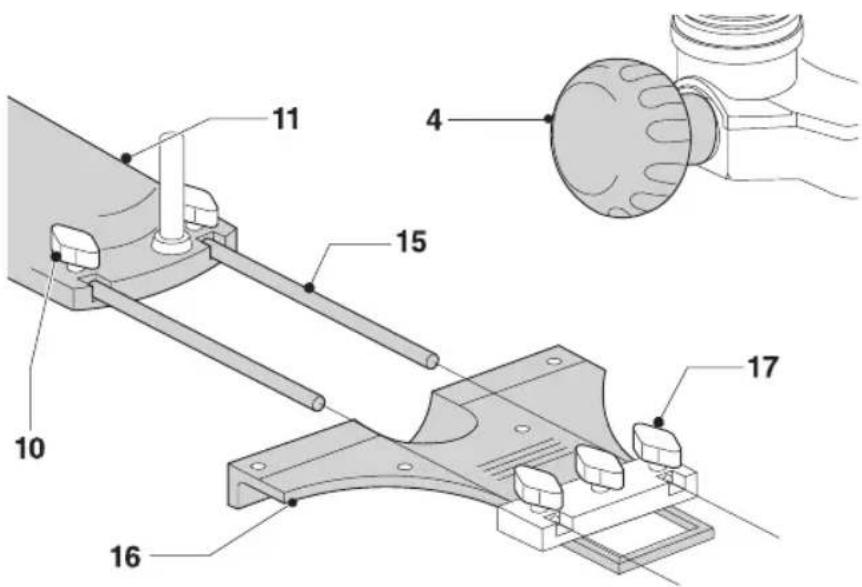
Fitting the Parallel Fence (fig. A, E)
- Fit the guide rods (15) to the router base (11).
- Tighten the locking bolts (10).
- Slide the parallel fence (16) over the rods.
- Tighten the locking bolts (17) temporarily.
Adjusting the Parallel Fence (fig. E)
- Draw a cutting line on the material.
- Lower the router carriage until the cutter is in contact with the workpiece.
- Tighten the plunge limiter (4).
- Position the router on the cutting line. The outer cutting edge of the cutter must coincide with the cutting line.
- Slide the parallel fence (16) against the workpiece and tighten the locking bolts (17).
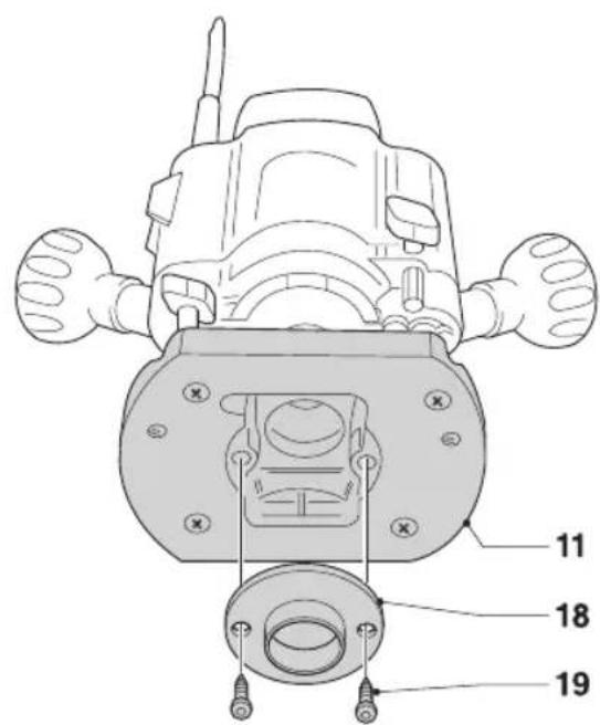
Fitting a Guide Bush (fig. F)
Together with a template, guide bushes play a valuable part in cutting and shaping to a pattern.
- Fit the guide bush (18) to the router base (11) using the screws (19) as shown.

G:The screws (19) also hold the dust extraction channel. Never operate the router without this.

Connecting a Dust Extractor (fig. A)
Connect a dust extractor hose to the dust extraction channel (9).
Prior to Operation
- Check that the cutter is correctly installed in the collet.
- Set the cutting depth.
- Connect a dust extractor.
- Always make sure the plunge limiter is locked before switching ON.
OPERATION
Instructions for use
WARNING: Always observe the safety instructions and applicable regulations.

IG: To reduce the risk of serious personal injury, turn tool off and disconnect tool from power source before making any adjustments or removing/installing attachments or accessories.

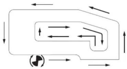
WARNING: Always move your router as indicated in fig. G (outer edges/inner edges).
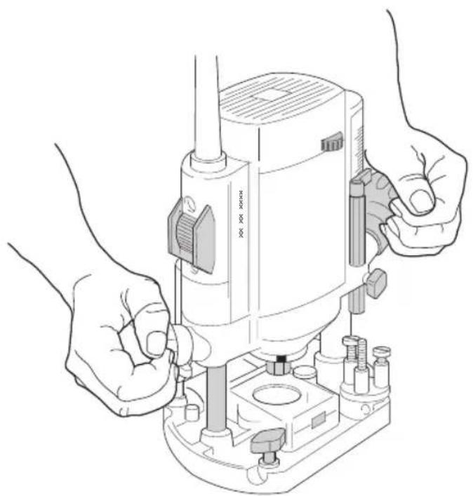
Proper Hand Position (fig. A, H)

WARNING: To reduce the risk of serious personal injury, ALWAYS use proper hand position as shown.

WARNING: To reduce the risk of serious personal injury, ALWAYS hold securely in anticipation of a sudden reaction.
Proper hand position requires one hand on each of the plunge limiters (4).
Switching On and Off (fig. A)
Switch the tool on using the on/off-switch (1).
I = on . The tool now works continuously.
$$ O = o f f. $$

WARNING: Loosen the plunge limiter and allow the router carriage to regain its rest position before switching off.
Using the Guide Bushes (fig. F)
- Secure the template to the workpiece using end clamps.
- Select and install an appropriate guide bush (18).
- Subtract the diameter of the cutter from the outside diameter of the guide bush and divide by 2. This will indicate how much larger the template should be in relation to the part being recessed.

WARNING: If the workpiece is not thick enough, place it on a piece of waste wood.
Guiding Off a Batten
Where an edge guide cannot be used, it is also possible to guide the router along a batten clamped across the workpiece (with an overhang at both ends).
Freehand Routing
Your router can also be used without any sort of guide, e.g. for signwriting or creative work.

WARNING: Make shallow cuts only! Use cutters with a max. diameter of 6 mm.
Routing with Pilot Cutters (fig. B)
Where a parallel guide or guide bush are inappropriate, it is possible to use pilot cutters (20) for cutting shaped edges.
Consult your dealer for further information on the appropriate accessories.
These include finger jointing tools for dovetail and finger jointing jigs, dowel jointing templates, guide bushes, fine height adjusters, trammel bars and guide rails in various lengths.
MAINTENANCE
Your DEWALT power tool has been designed to operate over a long period of time with a minimum of maintenance. Continuous satisfactory operation depends upon proper tool care and regular cleaning.
WARNING: To reduce the risk of injury, turn unit off and disconnect machine from power source before installing and removing accessories, before adjusting or changing setups or when making repairs. Be sure the trigger switch is in the OFF position. An accidental start-up can cause injury.

Lubrication
Your power tool requires no additional lubrication.

Cleaning

WARNING: Blow dirt and dust out of the main housing with dry air as often as dirt is seen collecting in and around the air vents. Wear approved eye protection and approved dust mask when performing this procedure.

WARNING: Never use solvents or other harsh chemicals for cleaning the non-metallic parts of the tool. These chemicals may weaken the materials used in these parts. Use a cloth dampened only with water and mild soap. Never let any liquid get inside the tool; never immerse any part of the tool into a liquid.
Optional Accessories

WARNING: Since accessories, other than those offered by DEWALT, have not been tested with this product, use of such accessories with this tool could be hazardous. To reduce the risk of injury, only DEWALT, recommended accessories should be used with this product.
Consult your dealer for further information on the appropriate accessories.
Protecting the Environment

Separate collection. Products and batteries marked with this symbol must not be disposed of with normal household waste.
Products and batteries contain materials that can be recovered or recycled reducing the demand for raw materials. Please recycle electrical products and batteries according to local provisions. Further information is available at www.2helpU.com.
FRESADORADW614, DW615
jEnhorabuena!
DEFONCEUSE DW614, DW615
Felicitations!
DEFONCEUSE DW614, DW615
ELETTROFRESATRICE DW614, DW615
BOVENFREES DW614, DW615
Gefeliciteerd!
BOVENFREES DW614, DW615
Director Engineering
DEWALT, Richard-Slinger-Strase 11,
BEWAAR ALLE WAARSCHUWINGEN EN INSTRUCTIES ALS TOEKOMSTIG REFERENTIEMATERIALAAL
1 Controller of de frees correct in de spontang is gemonteerd.
NEDERLANDS
HANDOVERFRES DW614, DW615
ADVARSEL:DW614, DW615 maks diameter for bruk:
-
Rett, fals- eller profilres med mak skaftdiameter pa 8 mm, maks diameter 36 mm og maks kuttedybe pa 10 mm;
-
Slissefres med maks skaftdiameter pa 8 mm og maks diameter 25 mm;
- Sporkriv med maks skaftdiameter pa 8 mm, maks diameter pa 40mm og fresebredde pa 4mm .
Director de Engenharia
KASIYLÄJYRSIN DW614, DW615
Onnittelut!
KASIYLAJYRSIN DW614, DW615
D-65510, Idstein, Germany
08.06.2015

HANDÖVERFRÄS DW614, DW615
Gratular!
HANDOVERFRAS DW614, DW615