DCW620 - Router DEWALT - Free user manual and instructions
Find the device manual for free DCW620 DEWALT in PDF.

| Brand | DeWalt |
| Model | DCW620 |
| Product Type | Cordless Router (plunge router) |
| Nominal Voltage | 18 V / 20 V Max (Li-Ion) |
| Weight (without battery pack) | 8 lb (approx. 3.6 kg) |
| No-load speed | 11,000 to 23,000 rpm (7 speeds) |
| Plunge stroke | 70 mm |
| Adjustable cutting depth | 0 - 80 mm |
| Maximum bit diameter | 63 mm (2-1/2 in) |
| Collet sizes | 1/4 in (6.35 mm) and 1/2 in (12.7 mm) |
| Power source | DeWalt 18 V / 20 V Max battery pack (not included) |
| Motor type | Brushless (integrated electronics, soft start) |
| Key features | Variable speed, plunge, multi-position turret stop, micro depth adjustment, edge guide, LED lighting, anti-kickback system, Tool Control™ wireless compatible, dust extraction |
| Worklight | 2 LED lights (turn off 20 seconds after stop) |
| Heavy load indicator | Triangular LED (flashes if overload) |
| Anti-kickback system | Motion detection and automatic shut-off (red LED) |
| Tool Connect™ compatibility | Slot for optional chip (inventory management) |
| Maintenance and cleaning | Blow vents with dry air weekly; clean plunge rods with dry cloth; lubricate with Teflon™ dry lubricant if necessary; do not immerse |
| Spare parts and repairability | Battery pack and charger not repairable; tool repairable by authorized DeWalt service center; use identical parts |
| Warranty | Limited 3-year (see conditions at www.dewalt.com) |
| General information | Professional heavy-duty use on wood, laminates, plastics; do not cut metal; storage temperature max 40 °C |
Frequently Asked Questions - DCW620 DEWALT
User questions about DCW620 DEWALT
0 question about this device. Answer the ones you know or ask your own.
Ask a new question about this device
Download the instructions for your Router in PDF format for free! Find your manual DCW620 - DEWALT and take your electronic device back in hand. On this page are published all the documents necessary for the use of your device. DCW620 by DEWALT.
USER MANUAL DCW620 DEWALT
English (original instructions) 6
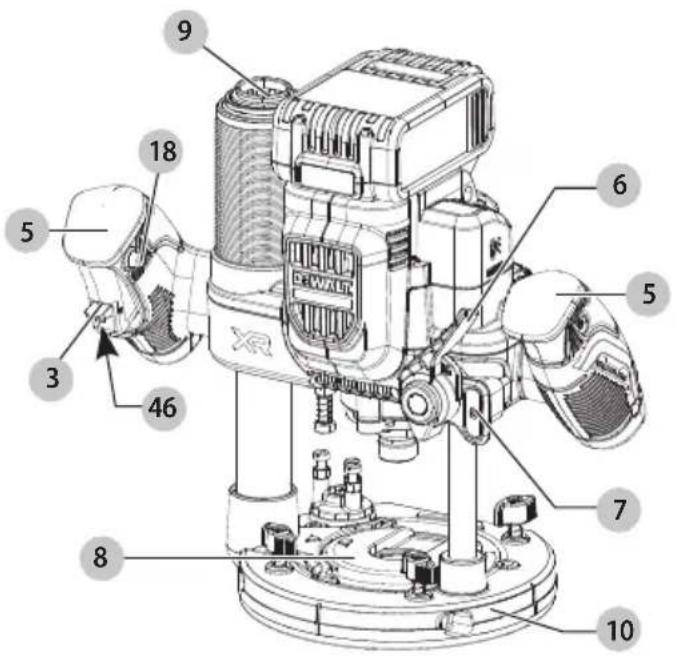
Components
1 Battery pack
2 Battery pack release button
3 On/off trigger switch
4 Variable speed dial
5 Main handles
6 Plunge lock lever
7 Plunge release lever
8 Dust cap
9 Dust column
10 Base plate
11 Spindle lock button
12 Collet
13 Multiple position turret stop
14 Depth stop bar/rod
15 22 mm wrench
16 Depth indicator
17 Micro height adjustment
18 Lock on button switch
Composants
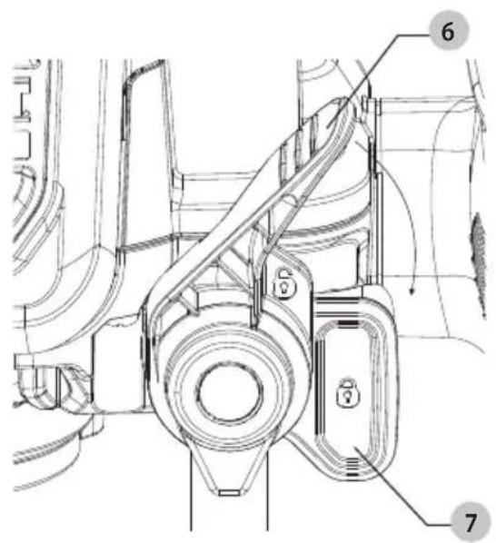
Fig. F Fig. G
1/2"(12.7 mm)
1/4"(6.35 mm)
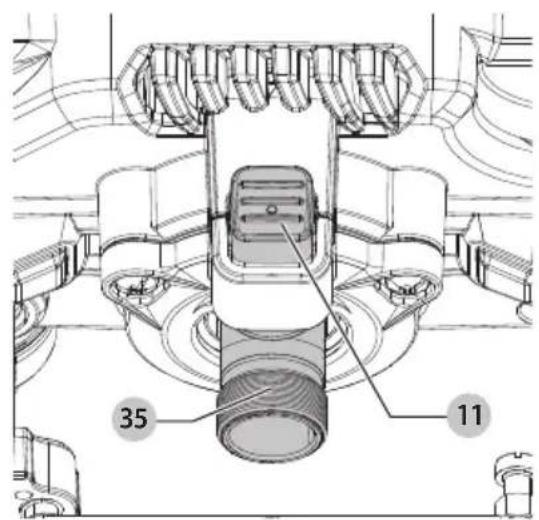
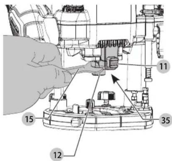
Fig. H
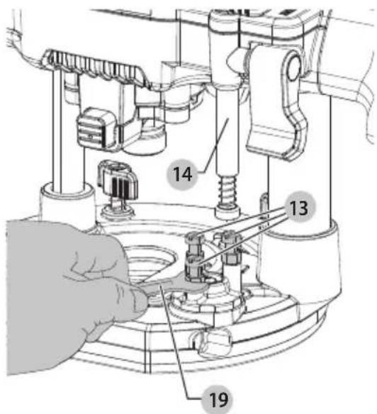
Fig.1
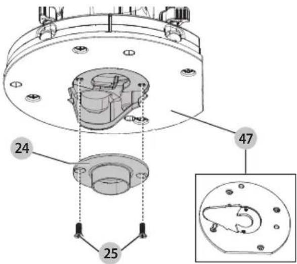
Fig. J
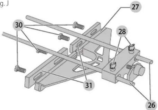
Fig. K
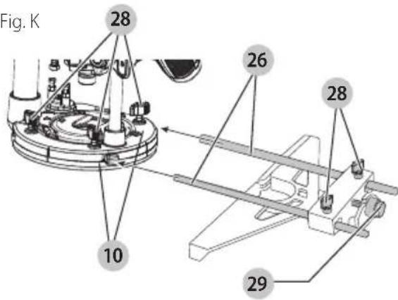
Fig. L
natural_image
Illustration of two wooden components with labeled parts, showing a saw and a cross-section view (no text or symbols present)Fig. M
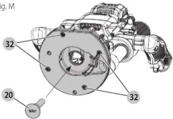
Fig. N
natural_image
Technical illustration of a mechanical assembly with labeled component 38 (no text or symbols beyond label)Fig. O
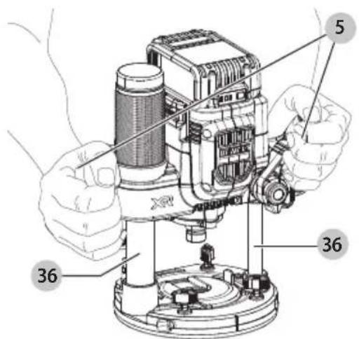
Fig. P1
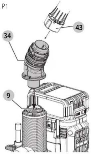
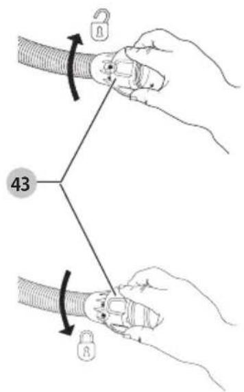
Fig. P2
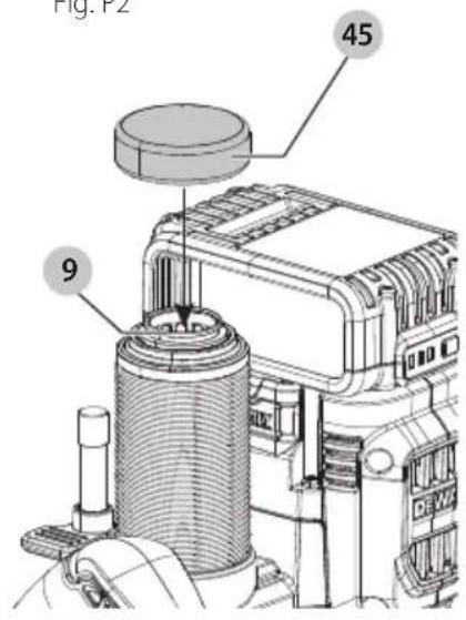
Fig. Q

natural_image
Technical line drawing of a mechanical assembly with no visible text or symbolsFig. R1
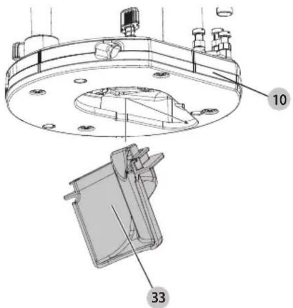
Fig. R2
natural_image
Technical line drawing of a mechanical assembly with no visible text or symbols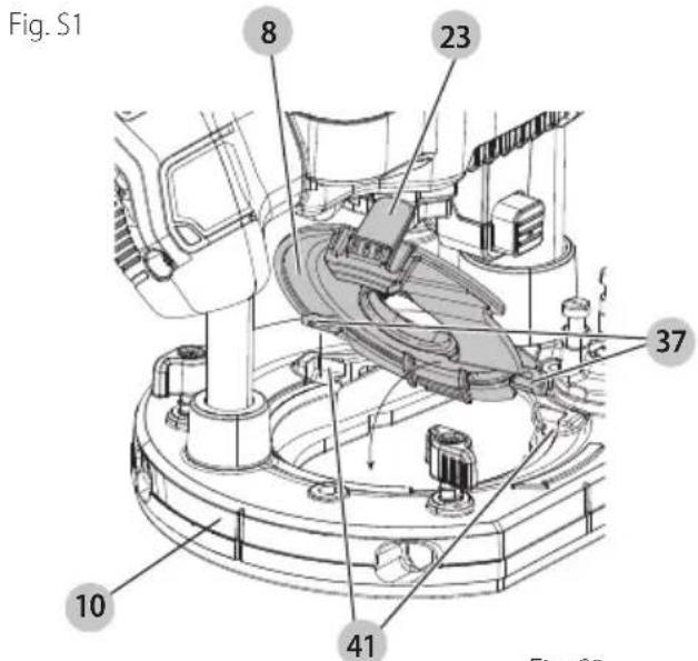
natural_image
Technical line drawing of a mechanical component with concentric rings and a central bracket, labeled Fig. S3 (50 mm)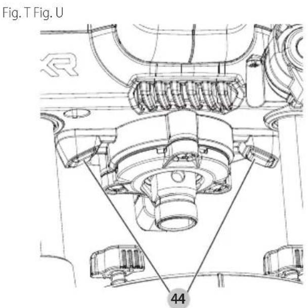
English
WARNING: Read all safety warnings and all instructions. Failure to follow the warnings and instructions may result in electric shock, fire and/or serious injury.

WARNING: To reduce the risk of injury, read the instruction manual.
Intended Use
This router has been designed for professional heavy duty routing of wood, wood based materials, composite laminate, and plastics.
This router is intended for routing grooves, edges, profiles and slots as well as copy routing.
DO nOT use under wet conditions or in presence of flammable liquids or gases.
This is a professional power tool.
DO nOT let children come into contact with the tool.
Supervision is required when inexperienced operators use this tool.
Definitions: Safety Alert Symbols and Words
This instruction manual uses the following safety alert symbols and words to alert you to hazardous situations and your risk of personal injury or property damage.
DANGER: Indicates an imminently hazardous situation which, if not avoided, will result in death or serious injury.
WARNING: Indicates a potentially hazardous situation which, if not avoided, could result in death or serious injury.
CAUTION: Indicates a potentially hazardous situation which, if not avoided, may result in minor or moderate injury.
(Used without word) Indicates a safety needed message.
NOTICE: Indicates a practice not related to personal injury which, if not avoided, may result in property damage.
GENERAL POWER TOOL SAFETY WARNINGS
WARNING: Read all safety warnings, instructions, indications and specifications provided with this power tool. Failure to follow all instructions listed below may result in electric shock, fire and/or serious injury.
SAVE ALL WARNINGS AND INSTRUCTIONS FOR FUTURE REFERENCE.
The term "power tool" in the warnings refers to your mains-operated (corded) power tool or battery-operated (cordless) power tool.
1) Work Area Safety
a) Keep work area clean and well lit. Cluttered or dark areas invite accidents.
b) Do not operate power tools in explosive atmospheres, such as in the presence of
flammable liquids, gases or dust. Power tools create sparks which may ignite the dust or fumes.
c) Keep children and bystanders away while operating a power tool. Distractions can cause you to lose control.
2) Electrical Safety
a) Power tool plugs must match the outlet. Never modify the plug in any way. Do not use any adapter plugs with earthed (grounded) power tools. Unmodified plugs and matching outlets will reduce risk of electric shock.
b) Avoid body contact with earthed or grounded surfaces, such as pipes, radiators, ranges and refrigerators. There is an increased risk of electric shock if your body is earthed or grounded.
c) Do not expose power tools to rain or wet conditions. Water entering a power tool will increase the risk of electric shock.
d) Do not abuse the cord. Never use the cord for carrying, pulling or unplugging the power tool. Keep cord away from heat, oil, sharp edges or moving parts. Damaged or entangled cords increase the risk of electric shock.
e) When operating a power tool outdoors, use an extension cord suitable for outdoor use. Use of a cord suitable for outdoor use reduces the risk of electric shock.
f) If operating a power tool in a damp location is unavoidable, use a ground fault circuit interrupter (GFCI) protected supply. Use of a GFCI reduces the risk of electric shock.
3) Personal Safety
a) Stay alert, watch what you are doing and use common sense when operating a power tool. Do not use a power tool while you are tired or under the influence of drugs, alcohol or medication. A moment of inattention while operating power tools may result in serious personal injury.
b) Use personal protective equipment. Always wear eye protection. Protective equipment such as a dust mask, non-skid safety shoes, hard hat, or hearing protection used for appropriate conditions will reduce personal injuries.
c) Prevent unintentional starting. Ensure the switch is in the off position before connecting to power source and/or battery pack, picking up or carrying the tool. Carrying power tools with your finger on the switch or energizing power tools that have the switch on invites accidents.
d) Remove any adjusting key or wrench before turning the power tool on. A wrench or a key left attached to a rotating part of the power tool may result in personal injury.
e) Do not overreach. Keep proper footing and balance at all times. This enables better control of the power tool in unexpected situations.
f) Dress properly. Do not wear loose clothing or jewelry. Keep your hair, clothing and gloves away
from moving parts. Loose clothes, jewelry or long hair can be caught in moving parts.
g) If devices are provided for the connection of dust extraction and collection facilities, ensure these are connected and properly used. Use of dust collection can reduce dust-related hazards.
h) Do not let familiarity gained from frequent use of tools allow you to become complacent and ignore tool safety principles. A careless action can cause severe injury within a fraction of a second.
4) Power Tool Use and Care
a) Do not force the power tool. Use the correct power tool for your application. The correct power tool will do the job better and safer at the rate for which it was designed.
b) Do not use the power tool if the switch does not turn it on and off. Any power tool that cannot be controlled with the switch is dangerous and must be repaired.
c) Disconnect the plug from the power source and/or remove the battery pack, if detachable, from the power tool before making any adjustments, changing accessories, or storing power tools. Such preventive safety measures reduce the risk of starting the power tool accidentally.
d) Store idle power tools out of the reach of children and do not allow persons unfamiliar with the power tool or these instructions to operate the power tool. Power tools are dangerous in the hands of untrained users.
e) Maintain power tools and accessories. Check for misalignment or binding of moving parts, breakage of parts and any other condition that may affect the power tool's operation. If damaged, have the power tool repaired before use. Many accidents are caused by poorly maintained power tools.
f) Keep cutting tools sharp and clean. Properly maintained cutting tools with sharp cutting edges are less likely to bind and are easier to control.
g) Use the power tool, accessories and tool bits, etc. in accordance with these instructions, taking into account the working conditions and the work to be performed. Use of the power tool for operations different from those intended could result in a hazardous situation.
h) Keep handles and grasping surfaces dry, clean and free from oil and grease. Slippery handles and grasping surfaces do not allow for safe handling and control of the tool in unexpected situations.
5) Battery Tool Use and Care
a) Recharge only with the charger specified by the manufacturer. A charger that is suitable for one type of battery pack may create a risk of fire when used with another battery pack.
b) Use power tools only with specifically designated battery packs. Use of any other battery packs may create a risk of injury and fire.
c) When battery pack is not in use, keep it away from other metal objects, like paper clips, coins, keys, nails, screws or other small metal objects, that can make a connection from one terminal to another. Shorting the battery terminals together may cause burns or a fire.
d) Under abusive conditions, liquid may be ejected from the battery; avoid contact. If contact accidentally occurs, flush with water. If liquid contacts eyes, additionally seek medical help.
Liquid ejected from the battery may cause irritation or burns.
e) Do not use a battery pack or tool that is damaged or modified. Damaged or modified batteries may exhibit unpredictable behavior resulting in fire, explosion or risk of injury.
f) Do not expose a battery pack or tool to fire or excessive temperature. Exposure to fire or temperature above 265 °F (130 °C) may cause explosion.
g) Follow all charging instructions and do not charge the battery pack or tool outside the temperature range specified in the instructions.
Charging improperly or at temperatures outside the specified range may damage the battery and increase the risk of fire.
6) Service
a) Have your power tool serviced by a qualified repair person using only identical replacement parts. This will ensure that the safety of the power tool is maintained.
b) Never service damaged battery packs. Service of battery packs should only be performed by the manufacturer or authorized service providers.
Safety Instructions for Routers
a) Hold the power tool by insulated gripping surfaces only, because the bit may contact its own cord. Cutting a "live" wire may make exposed metal parts of the power tool "live" and could give the operator an electrical shock.
b) Use clamps or another practical way to secure and support the workpiece to a stable platform. Holding the work by your hand or against the body leaves it unstable and may lead to loss of control.
c) Keep handles dry, clean and free from oil and grease. This will enable better control of the tool.
d) Maintain a firm grip with both hands on the tool to resist starting torque. Maintain a firm grip on the tool at all times while operating.
e) Keep hands away from cutting area above and below the base. Never reach under the workpiece for any reason. Keep the router base firmly in contact with the workpiece when cutting.
f) Never touch the bit immediately after use. Danger of burning bit—may extremely hot.
g) Be sure that the motor has stopped completely before you lay the router down. If the bit is still spinning when the tool is laid down, it could cause injury or damage.
English
h) Be sure that the router bit is clear of the workpiece before starting the motor. If the bit is in contact with the workpiece when the motor starts, it could make the router jump, causing damage or injury.
i) The permitted speed of the cutting bit must be at least equal to the maximum speed marked on the power tool. If cutting bits run faster than their rated speed, they may break and fly off.
j) Always follow the bit manufacturer's speed recommendations as some bit designs require specific speeds for safety or performance. If you are unsure of the proper speed or are experiencing any type of problem, contact the bit manufacturer.
k) Do not use router bits with a diameter in excess of 2-1/2" (63 mm) in this tool.
1) Keep cutting pressure constant. Too high of a pressure can overload the motor or damage the workpiece.
m) Provide clearance under workpiece for bit when through-cutting. There is a risk of cutting into objects below the workpiece.
n) Do not press spindle lock button while the motor is running. Doing so can damage the spindle lock.
o) Always make sure the work surface is free from nails and other foreign objects. Cutting into a nail can cause the bit and the tool to jump.
p) Before starting the motor, clear the work area of all foreign objects.
q) Keep handles and gripping surfaces dry, clean, and free from oil and grease. This will enable better control of the tool.
r) Maintain firm grip with both hands on tool to resist starting torques. Maintain a firm grip on the tool at all times while operating.
s) Keep hands away from cutting area above and below the base. Never reach under the workpiece for any reason. Keep the router base firmly in contact with the workpiece when cutting.
t) NEVER touch the bit immediately after use. It may be extremely hot.
u) Provide clearance under workpiece for bit when through-cutting.
v) Use sharp bits. Dull bits may cause the router to swerve or stall under pressure.
w) Do not use blunt or damaged cutting bits. Blunt or damaged cutting bits cause increased friction, create imbalances and may become jammed.
x) DO NOT CUT METAL.
Additional Safety Information
WARNING: Never modify the power tool or any part of damage or personal injury could result.
WARNING: ALWAYS use safety glasses. Everyday eyeglasses are NOT safety glasses. Also use face or dust mask if cutting operation is dusty. ALWAYS WEAR CERTIFIED SAFETY EQUIPMENT:
• ANSI Z87.1 eye protection (CAN/CSA Z94.3),
• ANSI S12.6 (S3.19) hearing protection,
• NIOSH/OSHA/MSHA respiratory protection.
WARNING: Some dust created by power sanding, sanding, grinding, drilling, and other construction activities contains chemicals known to the State of California to cause cancer, birth defects or other reproductive harm. Some examples of these chemicals are:
- lead from lead-based paints,
• crystalline silica from bricks and cement and other masonry products, and
• arsenic and chromium from chemically-treated lumber.
Your risk from these exposures varies, depending on how often you do this type of work. To reduce your exposure to these chemicals: work in a well ventilated area, and work with approved safety equipment, such as those dust masks that are specially designed to filter out microscopic particles.
- Wear protective clothing and wash exposed areas with soap and water. Allowing dust to get into your mouth, eyes, or lay on the skin may promote absorption of harmful chemicals. Direct particles away from face and body.
- Use the appropriate dust extractor vacuum to remove the vast majority of static and airborne dust. Failure to remove static and airborne dust could contaminate the working environment or pose an increased health risk to the operator and those in close proximity.
- Use clamps or other practical ways to secure and support the workpiece to a stable platform. Holding the work by hand or against your body is unstable and may lead to loss of control and injury.
• Air vents often cover moving parts and should be avoided. Loose clothes, jewelry or long hair can be caught in moving parts.
CAUTION: When not in use, place tool on its side on a stable surface where it will not cause
a tripping or falling hazard. Some tools with large battery packs will stand upright on the battery pack but may be easily knocked over.
The label on your tool may include the following symbols. The symbols and their definitions are as follows:
V....volts
Hz hertz
min......minutes
= or DC.....direct current
Class I Construction (grounded)
.../min.....per minute
BPM.....beats per minute
☐ Class II Construction (double insulated)
n_0 ......no load speed n ......rated speed
PSI..... pounds per square inch
± earthing terminal
⚠️......safety alert symbol
▲......visible radiation—do not stare into the light
E....wearrespiratory protection
∞...... wear eye protection
○....wearhearing protection
read all documentation
do not expose to rain
BATTERIES AND CHARGERS
The battery pack is not fully charged out of the carton. Before using the battery pack and charger, read the safety instructions below and then follow charging procedures outlined. When ordering replacement battery packs, be sure to include the catalog number and voltage.
READ ALL INSTRUCTIONS
Important Safety Instructions for All Battery Packs
WARNING: Read all safety warnings, instructions, and cautionary markings for the battery pack, charger and product. Failure to follow the warnings and instructions may result in electric shock, fire and/or serious injury.
- Do not charge or use the battery pack in explosive atmospheres, such as in the presence of flammable liquids, gases or dust. Inserting or removing the battery pack from the charger may ignite the dust or fumes.
- NEVER force the battery pack into the charger. DO NOT modify the battery pack in any way to fit into a non-compatible charger as battery pack may rupture causing serious personal injury. Consult the chart at the end of this manual for compatibility of batteries and chargers.
• Charge the battery packs only in DEWALT chargers.
• DO NOT splash or immerse in water or other liquids.
• DO NOT allow water or any liquid to enter battery pack.
- Do not store or use the tool and battery pack in locations where the temperature may reach or exceed 104 °F (40 °C) (such as outside sheds or metal buildings in summer). For best life, store battery packs in a cool, dry location.
NOTE: Do not store the battery packs in a tool with the trigger switch locked on. Never tape the trigger switch in the ON position.
- Do not incinerate the battery pack even if it is severely damaged or is completely worn out. The battery pack can explode in a fire. Toxic fumes and materials are created when lithium-ion battery packs are burned.
- Do not expose a battery pack or appliance to fire or excessive temperature. Exposure to fire or temperature above 265 °F (130 °C) may cause explosion.
- Follow all charging instructions and do not charge the battery pack or appliance outside of the temperature range specified in the instructions. Charging improperly or at temperatures outside of the specified range may damage the battery and increase the risk of fire.
- If battery contents come into contact with the skin, immediately wash area with mild soap and water. If battery liquid gets into the eye, rinse water over the open eye for 15 minutes or until irritation ceases. If medical attention is needed, the battery electrolyte is composed of a mixture of liquid organic carbonates and lithium salts.
- Contents of opened battery cells may cause respiratory irritation. Provide fresh air. If symptoms persist, seek medical attention.
- Battery liquid may be flammable if exposed to spark or flame.
- Never attempt to open the battery pack for any reason. If the battery pack case is cracked or damaged, do not insert into the charger. Do not crush, drop or damage the battery pack. Do not use a battery pack or charger that has received a sharp blow, been dropped, run over or damaged in any way (e.g., pierced with a nail, hit with a hammer, stepped on). Damaged battery packs should be returned to the service center for recycling.
Storage Recommendations
The best storage place is one that is cool and dry, away from direct sunlight and excess heat or cold. Store the fully charged battery pack out of the charger.
For long storage, it is recommended to store a fully charged battery pack in a cool dry place out of the charger for optimal results.
Battery Pack Cleaning Instructions
Dirt and grease may be removed from the exterior of the battery pack using a cloth or soft non-metallic brush. Do not use water or any cleaning solutions.
Fuel Gauge Battery Packs (Fig. B)
Some battery packs include a fuel gauge. When the fuel gauge button is pressed and held, the LED lights will indicate the approximate level of charge remaining. This does not indicate tool functionality and is subject to variation based on product components, temperature, and end-user application.
Transportation
WARNING: Fire hazard. Do not store, carry, or transport the battery pack so that metal objects can contact exposed battery terminals. For example, do not place the battery pack in aprons, pockets, tool boxes, product kit boxes, drawers, etc., with loose nails, screws, keys, coins, hand tools, etc. When transporting individual battery packs, make sure that the battery terminals are protected and well insulated from materials that could contact them and cause a short circuit. NOTE: Li-ion battery packs should not be put in checked baggage on airplanes and must be properly protected from short circuits if they are in carry-on baggage.
Shipping the DEWALT FLEXVOLT® Battery Pack
The DEWALT FLEXVOLT® battery pack has a battery cap that should be used when shipping the battery pack.
Attach the cap to the battery pack to ready it for shipping. This converts the battery pack to three separate 20V batteries. The three batteries have the Watt hour rating labeled "Shipping" on the battery pack. If shipping without
ENGLISH
the cap or in a tool, the pack is one battery at the Watt hour rating labeled "Use."
Example battery pack label:
USE: 120 Wh SHIPPING: 3 x 40 Wh
In this example, the battery pack is three batteries with 40 Watt hours each when using the cap. Otherwise, the battery pack is one battery with 120 Watt hours.
The RBRC® Seal
Please take your spent battery packs to an authorized DEWALT service center or to your local retailer for recycling. In some areas, it is illegal to place spent battery packs in the trash. You may also contact your local recycling center for information on where to drop off the spent battery pack. Do not place in curbside recycling. For more information visit www.call2recycle.org or call the toll-free number in the RBRC® Seal.

RBRC ^® is a registered trademark of Call 2 Recycle, Inc.
Important Safety Instructions for All Battery Chargers
WARNING: Read all safety warnings, instructions, and cautionary markings for the battery pack, charger and product. Failure to follow the warnings and instructions may result in electric shock, fire and/or serious injury.
- DO NOT attempt to charge the battery pack with any chargers other than a DEWALT charger. DEWALT chargers and battery packs are specifically designed to work together.
• These chargers are not intended for any uses other than charging DEWALT rechargeable battery packs. Charging other types of battery packs may cause them to overheat and burst, resulting in personal injury, property damage, fire, electric shock or electrocution. - Do not expose the charger to rain or snow.
- Do not allow water or any liquid to enter charger.
- Pull by the plug rather than the cord when disconnecting the charger. This will reduce the risk of damage to the electric plug and cord.
- Make sure that the cord is located so that it will not be stepped on, tripped over or otherwise subjected to damage or stress.
- Do not use an extension cord unless it is absolutely necessary. Use of improper extension cord could result in risk of fire, electric shock or electrocution.
- When operating a charger outdoors, always provide a dry location and use an extension cord suitable for outdoor use. Use of a cord suitable for outdoor use reduces the risk of electric shock.
- An extension cord must have adequate wire size (AWG or American Wire Gauge) for safety. The smaller the gauge number of the wire, the heavier the cord and thus the greater its capacity. An undersized cord will cause a drop in line voltage resulting in loss of power and
overheating. The following table shows the correct size to use depending on total length of all extension cords plugged together, and nameplate ampere rating. If in doubt, use the next heavier gauge.
Minimum Gauge for Cord Sets
| Volts | Total Length of Cord in Feet (meters) | ||||
| 120V 25 (7.6) | 50 (15.2) 100 | (30.5) 150 (45.7) | |||
| Ampere Rating | American Wire Gauge | ||||
| More Than Not More Than | |||||
| 0 6 18 16 16 14 | |||||
| 6 10 18 16 14 12 | |||||
| 10 12 16 16 14 12 | |||||
| 12 16 14 12 Not Recommended | |||||
- Do not place any object on top of the charger or place the charger on a soft surface that might block the ventilation slots and result in excessive internal heat. Place the charger in a position away from any heat source. The charger is ventilated through slots in the top and the bottom of the housing.
- Do not operate the charger with a damaged cord or plug. Have them replaced immediately.
- Do not operate the charger if it has received a sharp blow, been dropped or otherwise damaged in any way. Take it to an authorized service center.
- Do not disassemble the charger; take it to an authorized service center when service or repair is required. Incorrect reassembly may result in a risk of electric shock, electrocution or fire.
- The charger is designed to operate on standard 120V household electrical power. Do not attempt to use it on any other voltage. This does not apply to the vehicular charger.
- Foreign materials of a conductive nature, such as, but not limited to, grinding dust, metal chips, steel wool, aluminum foil or any buildup of metallic particles should be kept away from the charger cavities and ventilation slots.
• Always unplug the charger from the power supply when there is no battery pack in the cavity.
Charging a Battery (Fig. C)
NOTE: To ensure maximum performance and life of Li-Ion battery packs, charge the battery pack fully before first use.
- Plug the charger into an appropriate outlet before inserting battery pack.
- Insert and fully seat battery pack. The charging light(s) will continuously blink indicating that the charging process has started.
For 2-Stage Chargers (DCB1102, DCB1104, DCB1106, DCB1112, DCB094)
Stage 1 Charging: Blink indicator represents the first charge cycle that charges the majority of the battery's capacity. Stage 2 Charging: Blink indicator represents the remainder, or top off charge process, for the battery to reach full capacity.
- Charging is complete when the charging light(s) remain(s) continuously ON. The battery pack is fully charged and may be removed and used at this time or left in the charger.
NOTE: To remove the battery pack, some chargers require the battery pack release button to be pressed.
WARNING: Only charge batteries in air temperature 10^ F (4.5 °C) and below 104^ F (40 °C).
Charger will not charge a faulty battery pack, which may be indicated by the charging light(s) staying OFF. Take charger and battery pack to an authorized service center if light(s) stay(s) OFF.
NOTE: Refer to label near charging light(s) on charger for blink patterns. Older chargers may have additional information and/or may not have a yellow indicator light.
Hot/Cold Pack Delay
When the charger detects a battery pack that is too hot or too cold, it automatically starts a Hot/Cold Pack Delay, suspending charging until the battery pack has reached an appropriate temperature. The charger then automatically switches to the pack charging mode. This feature ensures maximum battery pack life.
A cold battery pack may charge at a slower rate than a warm battery pack.
The hot/cold pack delay will be indicated by the red light(s) continuing to blink but with the yellow light continuously ON. Once the battery pack has reached an appropriate temperature, the yellow light will turn OFF and the charger will resume the charging procedure.
DCB118 and DCB1112 Chargers
The DCB118 and DCB1112 chargers are equipped with an internal fan designed to cool the battery pack. The fan will turn on automatically when the battery pack needs to be cooled. Never operate the charger if the fan does not operate properly or if ventilation slots are blocked. Do not permit foreign objects to enter the interior of the charger.
Electronic Protection System
Li-ion tools are designed with an Electronic Protection System that will protect the battery pack against overloading, overheating or deep discharge. The tool will automatically turn off and the battery pack will need to be recharged.
Important Charging Notes
- Longest life and best performance can be obtained if the battery pack is charged when the air temperature is between 65^ F – 75^ F ( 18^ C – 24^ C). DO NOT charge when the battery pack is below 40^ F ( 4.5^ C), or above 104^ F ( 40^ C). This is important and will prevent serious damage to the battery pack.
- The charger and battery pack may become warm to the touch while charging. This is a normal condition, and does not indicate a problem. To facilitate the cooling of the battery pack after use, avoid placing the charger or battery pack in a warm environment such as in a metal shed or an uninsulated trailer.
- If the battery pack does not charge properly:
a. Check operation of receptacle by plugging in a lamp or other appliance;
b. Check to see if receptacle is connected to a light switch which turns power off when you turn out the lights;
c. If charging problems persist, take the tool, battery pack and charger to your local service center.
- You may charge a partially used pack whenever you desire with no adverse effect on the battery pack.
Charger Cleaning Instructions
WARNING: Shock hazard. Disconnect the charger from the AC outlet before cleaning. Dirt and grease may be removed from the exterior of the charger using a cloth or soft non-metallic brush. Do not use water or any cleaning solutions.
Wall Mounting
Some DEWALT chargers are designed to be wall mountable or to sit upright on a table or work surface. If wall mounting, locate the charger within reach of an electrical outlet, and away from a corner or other obstructions which may impede air flow. Use the back of the charger as a template for the location of the mounting screws on the wall. Mount the charger securely using drywall screws (purchased separately) at least 1" (25.4 mm) long, with a screw head diameter of 0.28–0.35" (7–9 mm), screwed into wood to an optimal depth leaving approximately 7/32" (5.5 mm) of the screw exposed. Align the slots on the back of the charger with the exposed screws and fully engage them in the slots.
SAVE THESE INSTRUCTIONS FOR FUTURE USE
Technical Data
| DCW620 |
| Voltage 18V/20V Max |
| Weight (without battery) 8 lbs |
| No load speed 11000–23000 rpm |
| Plunging stroke 70 mm |
| Routing depth Adjustable, 0–3-5/32" (0–80 mm) |
| Bit diameter Maximum of 2-1/2" (63 mm) |
| Collet size 1/2" and 1/4" |
ASSEMBLY AND ADJUSTMENTS
WARNING: To reduce the risk of serious personal injury, turn unit off and remove the battery pack before making any adjustments or removing/installing attachments or accessories. An accidental start-up can cause injury.
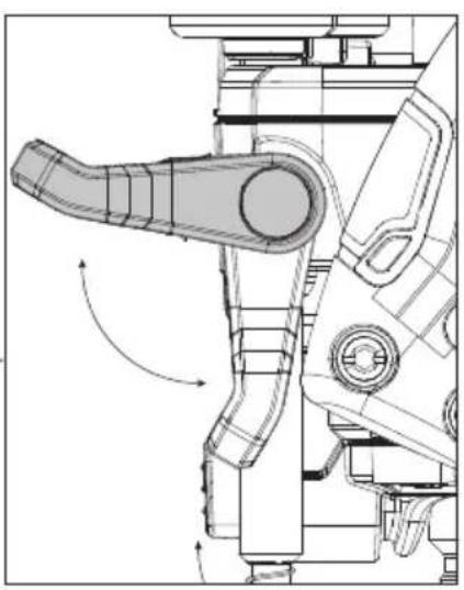
Plunge Lock Lever (Fig. E)
The plunge lock lever 6 allows you to stop the routing bit at a specified height.
- Unlock the plunge mechanism by pushing down on the plunge lock lever6 (refer to Fig. E).
- To keep the plunge lock lever open push the lever down until it clicks and stays in position.
English
- You can now move the router up and down freely.
- To lock the plunge depth of the tool, press the plunge release lever 7.
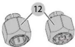
Collets (Fig. F)
WARNING: Projectile hazard. Only use bits with shanks that match the installed collet. Smaller shank bits will not be secure and could become loose during operation.
CAUTION: Never tighten the collet without first insciling a router bit in it. Tightening an empty collet, even by hand, can damage the collet.
Two collets 12 are included with the router.
- 1/4" (6.35 mm)
- 1/2" (12.7 mm)
Installing/Removing Collets
- To install a collet 12, press the spindle lock button 11 to lock the spindle 35.
- Attach the collet to the spindle and hand-tighten the collet by rotating it clockwise.
- To remove the collet, press the spindle lock button and loosen the collet by rotating counterclockwise.
NOTE: Using a wrench to fully tighten or loosen the collet will only be needed when installing or removing a bit. Refer to section Installing and Removing a Bit.
Installing and Removing a Bit (Fig. A, G)
WARNING: Do not tighten the collet without a locked.
WARNING: Always use bits with shanks which match the diameter of the collet.
WARNING: Do not use bits larger than 2-1/2" (63 mm).
CAUTION: Care should be taken when removing bit to a cut to fingers. Wearing protective gloves while fitting and changing router bits is recommended.
Installing a Bit
- Insert at least three-fourths of the shank length of the bit into the collet 12.
- Press the spindle lock button 11 to lock the spindle 35. nOTE: You may need to turn the spindle slightly to engage it.
- Turn the collet counterclockwise with the supplied 22 mm wrench 15 to tighten it.
- Tighten collet nut securely to prevent the bit from slipping.
Removing a Bit
- Press the spindle lock button 11 to lock the spindle 35.
- Turn the collet 12 clockwise with the supplied 22 mm wrench 15 to loosen.
- Keep turning the wrench until the collet tightens and then loosens again. This is the fail-safe mechanism releasing the collet.
- The bit should now slide out. nOTE: Each time you finish using a bit, remove it and store it in a safe place.
Multiple Position Turret Stop (Fig. H)
WARNING: Do not change the multiple position turret stop while the router is running. This will place your hands too near the bit head.
The multiple position turret stop 13 limits the downward distance that the tool can be plunged. It consists of three screws of different lengths that serve to define the depth of cut by limiting the travel of the depth stop bar/rod 14.
- Routing depth can be set by selecting the screw of the appropriate length on the turret.
- The turret is rotatable with detent stops to properly align the screws.
- It is the interaction of the depth stop bar/rod and the multiple position turret stop that determine the routing depth.
- If none of the provided screws seems close to the desired height each can be adjusted by loosening the hex nut at the bottom and then turning the screw either in or out to make it the proper length. After adjusting this screw be sure to tighten the hex nut at the bottom with an 8 mm wrench 19.
- Refer to section Adjusting the Plunge Routing Depth for instructions on how to use the multiple position turret stop in an actual operation.
Adjusting the Plunge Routing Depth
(Fig. A, E, Q)
WARNING: Laceration hazard. Do not change the multiple position turret stop while the router is running. This will place your hands too near the bit head.
WARNING: To prevent loss of control, ALWAYS target an the travel-limiting nuts together.
Inadvertent movement could prevent full bit retraction.
WARNING: To prevent loss of control, set the target-limiting nuts so that bit can be retracted into the base of the router, clear of the workpiece.
WARNING: To reduce the risk of injury, NEVER adjust or remove the stop nut. Motor can disengage resulting in loss of control.
CAUTION: Turn the router on before plunging the head into the workpiece.
- Unlock the plunge mechanism by pushing down the plunge lock lever 6. Gently push down on the two main handles 5 to plunge the router down as far as it will go, allowing the bit to just touch the workpiece.
- Lock the plunge mechanism by pushing the plunge release lever 7.
- Loosen the depth stop bar/rod 14 by pulling up on the depth stop lock lever 21.
- Slide the depth stop bar/rod down so that it meets the lowest multiple position turret stop 13.
-
Slide the depth indicator 16 on the depth stop bar/rod down so that the top of it meets zero on the depth adjustment scale 22.
-
Grasping the top, knurled section of the depth stop bar/rod, slide it up so that the depth indicator aligns with the desired depth of cut on the depth adjustment scale.
- Push down on the depth stop lock lever to hold the depth stop bar/rod in place.
- Keeping both hands on the handles, unlock the plunge mechanism by pushing down the plunge lock lever. The plunge mechanism and the motor will move up. When the router is plunged, the depth stop bar/rod will hit the multiple position turret stop, allowing the router to reach exactly the desired depth.
Fitting the Side Fence (Fig. J, K)
Optional accessory, sold separately.
NOTE: The side fence is available at extra cost from your local dealer or authorized service center.
- Fit the guide rods 26 to the base plate 10.
- Slide the side fence 27 over the guide rods.
- Tighten the wing bolts 28 temporarily.
Adjusting the Side Fence (Fig. A, J, K)
- Draw a cutting line on the material.
- Lower the router carriage until the bit is in contact with the workpiece.
- Push plunge release lever 7 and limit the carriage return.
- Position the router on the cutting line.
- Slide the side fence 27 against the workpiece and tighten the wing bolts 28.
- Adjust the side fence using the adjustment knob 29. The outer cutting edge of the bit must coincide with the cutting line.
- If required, loosen the screws 30 and adjust the strips 31 to obtain the desired guiding length.
Fitting a Guide Bushing (Fig. A, I)
Together with a template, the guide bushings play a valuable part in cutting and shaping to a pattern. For using a guide bushing with this tool please choose the subbase adaptor 47.
- Attach the guide bushing 24 to the subbase adaptor 47 using the screws 25 as shown.
- Center the guide bushing to the collet 12 by using the centering cone and tighten the subbase screws. Refer to section Centering the Subbase.
Connecting Dust Extractor Hose (Fig. P1, P2)
WARNING: Risk of dust inhalation. To reduce the personal injury, ALWAYS wear an approved dust mask.
WARNING: ALWAYS use a vacuum extractor designed in compliance with the applicable directives regarding dust emission when sawing wood. Vacuum hoses of most common vacuum cleaners will fit directly into the dust extraction outlet.
CAUTION: Do not operate the router without the trap if the router is not connected to a dust extraction system.
A dust extraction tube adaptor 34 is supplied with your tool. Vacuum hoses on most vacuum extractors will fit directly onto the dust column 9.
- Insert the dust extraction tube adaptor 34 into the top of the dust column 9 (Fig. P1).
- Connect a dust extractor hose 43 to the dust extraction tube adaptor 34 using the DEWALT quick lock system.
A dust cover 45 is supplied for use with your tool when a dust extraction system is not in use.
- Cover the dust column 9 with the dust cover 45 to seal up the tool (Fig. P2).
NOTE: When using dust extraction, be sure that the vacuum cleaner is out of the way and secure so that it will not tip over or interfere with the router or workpiece. The vacuum hose and power cord must also be positioned so that they do not interfere with the router or workpiece. If the vacuum cleaner or vacuum hose cannot be positioned properly, it should be removed.
OPERATION
WARNING: To reduce the risk of serious personal injury, turn unit off and remove the battery pack before making any adjustments or removing/installing attachments or accessories. An accidental start-up can cause injury.
CAUTION: Before connecting tool to power source, check to see that the switch is in the "OFF" position. An accidental start-up can cause injury.
Proper Hand Position (Fig. 0)
WARNING: To reduce the risk of serious personal injury, ALWAYS use proper hand position as shown. WARNING: To reduce the risk of serious personal injury, ALWAYS hold securely in anticipation of a sudden reaction.
Proper hand position requires both hands on the main handles 5.
Installing and Removing the Battery Pack (Fig. D)
CAUTION: Before inserting the battery, check to see that the switch is in the OFF position. An accidental start-up can cause injury.
NOTE: For best results, make sure your battery pack is fully charged.
To install the battery pack 1 into the tool handle, align the battery pack with the rails inside the tool's handle and slide it into the handle until the battery pack is firmly seated in the tool and ensure that it does not disengage.
To remove the battery pack from the tool, press the battery pack release button 2 and firmly pull the battery pack out of the tool handle. Insert it into the charger as described in the charger section of this manual.
English
Wireless Tool Control™ (Fig. A)
CAUTION: Read all safety warnings, instructions and specifications of the appliance which is paired with the tool.
Your tool is equipped with a Wireless Tool Control™ transmitter which allows your tool to be wirelessly paired with another Wireless Tool Control™ device, such as a dust extractor.
To pair your tool using Wireless Tool Control™, press and hold the Wireless Tool Control™ pairing button on your pairing device and squeeze the on/off trigger switch 3. An LED on the separate device will let you know when your tool has been successfully paired.
On/Off Trigger Switch (Fig. A)
WARNING: To reduce the risk of serious personal injury, turn unit off and remove the battery pack before making any adjustments or removing/installing attachments or accessories. An accidental start-up can cause injury.
WARNING: Be sure that the bit is clear of the workpiece before starting the motor. If the bit is in contact with the workpiece when the motor starts, it could make the router jump, causing damage or injury.
-
To turn the unit on, flip the lock-off lever 46 down towards the bottom of the main handle 5, then squeeze the on/off trigger switch 3. Continue to squeeze the on/off trigger switch or press the lock on button switch 18 for continuous running.
-
To turn the unit off:
a. If the lock on button switch is engaged, release the lock on button switch by squeezing and releasing the on/off trigger switch.
b. If the lock on button switch is not engaged, fully release the on/off trigger switch.
NOTE: Be sure that the motor has stopped completely before you lay the router down. If the bit is still spinning when the tool is laid down it could cause injury or damage.
Choosing Router Speed (Fig. A)
Refer to the Speed Selection Chart to choose a router speed. Turn the variable speed dial 4 to control router speed.
Soft Start Feature
The compact routers are equipped with electronics to provide a soft start feature that minimizes the start-up torque of the motor.
Variable Speed Dial (Fig. A)
WARNING: If the variable speed dial ceases to operate, or is intermittent, stop using the tool immediately. Take it to a DEWALT factory service center or a DEWALT authorized service center for repair.
WARNING: Always follow the bit manufacturer's speed recommendations as some bit designs require specific speeds for safety or performance. If you are unsure of the proper speed or are experiencing any type of problem, contact the bit manufacturer.
This router is equipped with a variable speed dial 4 with 7 speeds between 11000 and 23000 RPM. Adjust the speed by turning the variable speed dial.
NOTICE: The router is equipped with electronics to monitor and maintain the speed of the tool while cutting. In low and medium speed operation, the variable speed dial prevents the motor speed from decreasing. If you expect to hear a speed change and continue to load the motor, you could damage the motor by overheating. Reduce the depth of cut and/or slow the feed rate to prevent tool damage.
sPEED sELECTiOn ChART*
| DIAL SETTING APPROX. RPM | |
| 1 | 11000 |
| 2 | 13000 |
| 3 | 15000 |
| 4 | 17000 |
| 5 | 19000 |
| 6 | 21000 |
| 7 | 23000 |
| *The speeds in this chart are approximate and are for reference only. Your router may not exactly produce the speed listed for the dial setting. | |
NOTE: Make several light passes instead of one heavy pass for better quality work.
Using the Router (Fig. A, L, O)
CANTION: Turn the router on before plunging the bit has into the workpiece.
CAUTION:
- Excessive cutting may cause overload of the motor or difficulty in controlling the tool, the depth of cut should not be more than 19/32" (15 mm) at a pass when cutting grooves with a 5/16" (8 mm) diameter bit.
- When cutting grooves with a 25/32" (20 mm) diameter bit, the depth of cut should not be more than 3/16" (5 mm) at a pass.
- For extra deep grooving, make two or three passes with progressively deeper bit settings.
CAUTION:
• After long periods of working at low speeds, allow the machine to cool down by running it for three minutes at maximum speed, with no load.
All common routing tasks can be performed with the plunge cut router on all types of wood and plastic:
-Grooving
- Rabbeting
- Recessing
- Veining
- Profiling
NOTE: Only carbide-tipped bits should be used on panels faced with plastic laminates. The hard laminates will quickly dull steel bits.
NOTE: For better plunge sliding movement, frequently clean the plunge rods 36 of dust or debris with a DRY cloth only. If the plunging movement is not moving as smooth as desired, lubricate the plunge rods with a dry Teflon™ lubricant.
- After setting the cutting depth as described, locate the router so that the bit is directly over the place you will be cutting.
- With the router running, lower the unit smoothly down into the workpiece. DO NOT JAM THE ROUTER DOWN.
- When the tool reaches the pre-set depth, push the plunge release lever 7 to lock.
- When you have finished routing, push down on the plunge lock lever 6 to unlock and let the spring lift the router directly out of the workpiece.
- Always feed the router opposite to the direction in which the bit is rotating. Refer to Fig. L.
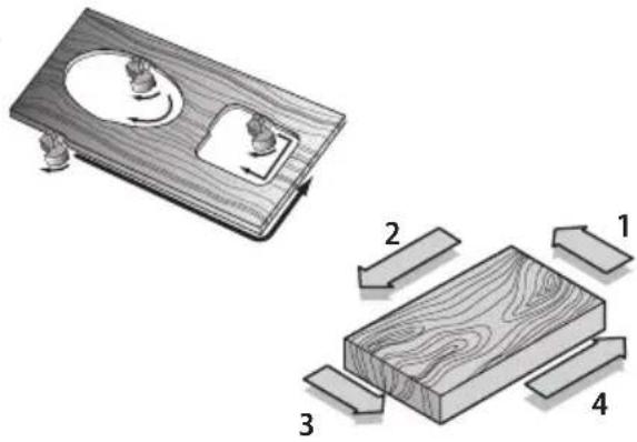
Moulding Natural Timbers
WARNING: When routing always lock the plunge locking lever.
When edge moulding natural timbers, always mould the end grain first, followed by the long grain. This ensures that if there is breakout, it will be removed when the long grain is routed.
Worklight LEDs (Fig. A, T)
CAUTION: Do not stare into worklight. Serious eye injury could result.
Two worklight LEDs 44 are located next to the collet 12.
- To turn on the worklight, switch on the on/off trigger switch 3. Worklights will remain on 20 seconds after the on/off switch is moved to the off position.
NOTE: The worklight is for lighting the immediate work surface and is not intended to be used as a flashlight.
NOTE: If worklights flash, check the charge on the battery; it could be low. If they still flash with a charged battery, the unit should be taken to a service center for evaluation.
Direction Of Feed (Fig. L)
WARNING: Avoid climb-cutting (cutting in direction opposite than shown in Fig. L). Climb-cutting increases the chance for loss of control resulting in possible injury. When climb-cutting is required (backing around a corner), exercise extreme caution to maintain control of router. Make smaller cuts and remove minimal material with each pass.
The direction of feed is very important when routing and can make the difference between a successful job and a ruined project. The figures show the proper direction of feed for some typical cuts. A general rule to follow is to move the router in a counterclockwise direction on an outside cut and a clockwise direction on an inside cut.
Shape the outside edge of a piece of stock by following these steps:
- Shape the end grain, left to right
- Shape the straight grain side moving left to right
- Cut the other end grain side
- Finish the remaining straight grain edge
Feed Load
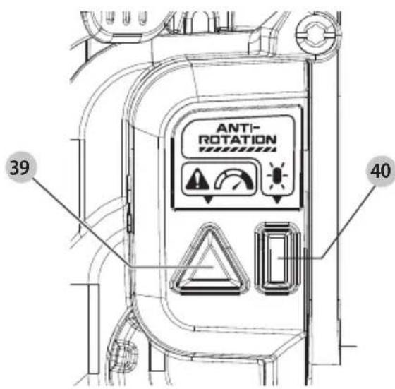
Heavy Load Indicator LED (Fig. U)
Your tool is equipped with a heavy load indicator LED 39. If the heavy load Indicator LED white triangle is flashing, slow down the speed of the tool.
The speed at which the bit is fed into the wood must not be too fast that the motor slows down, or too slow that the bit leaves burn marks on the face of the wood.
NOTE: Practice judging the speed by listening to the sound of the motor when routing.
Anti-Rotation System (Fig. U)
Your tool is equipped with the DEWALT anti-rotation system. This feature senses the motion of the tool and shuts the tool down if necessary. The red LED indicator 40 illuminates when the anti-rotation system is engaged.
INDICATOR DIAGNOSIS SOLUTION
| OFF Tool is functioning normally | Follow all warnings and instructions when operating the tool. |
| SOLID RED Anti-Rotation System has been activated (ENGAGED) | With the tool properly supported, release trigger. The tool will function normally when the trigger is depressed again and the indicator light will go out. |
Sequence of Plunging (Fig. A)
WARNING: When routing always lock the plunge locking lever.
- Plunge down and lock the motor carriage, by pushing the plunge release lever 7.
- Perform the desired routing operation.
- Push down the plunge lock lever 6 and the motor carriage returns to the normal position.
Side Fence Routing (Fig. J)
The side fence is used to guide the router when moulding, edge profiling or rebating the edge of a workpiece or when routing grooves and slots in the center of the workpiece, parallel to the edge.
The edge of the workpiece must be straight and true.
The strips 31 are adjustable and should be set ideally with a 1/8" (3 mm) gap each side of the bit.
Using a Side Fence (Fig. A, K)
CAUTION: Ensure working position is comfortable and a desirable working height.
- Ensure the wing bolts 28 are fully released. Slide the guide rods 26 into the base plate 10 and tighten the wing bolts.
- Adjust the adjustment knob 29 to the required distance and clamp in place with the wing bolts.
- Then lower the bit height until the bit is just above the workpiece.
- Fine adjustments are possible by loosening the wing bolt and adjusting the side fence adjustment knob.
ENGLISH
- Tighten the wing bolt to secure the position.
NOTE: One revolution of the adjustment knob equals 3/64" (1.0 mm) of side feed. - Lower the bit onto the workpiece and set the bit height to the required distance. Refer to Adjusting the Plunge Routing Depth.
- Switch the router on and after the bit reaches full speed, gently lower the bit into the workpiece and lock the plunge.
- Feed along the workpiece, keeping sideways pressure to ensure the side fence does not wander away from the workpiece edge and downward pressure on the inside hand to prevent the router from tipping.
- When finished, raise the router, secure with the plunge lock lever 6 and switch the router off.
NOTE: When starting the cut, keep the pressure on the front cheek until the back cheek contacts the workpiece edge.
NOTE: At the end of the cut, keep pressure on the back cheek until the cut is finished. This will prevent the router bit swinging in at the end of the workpiece and nipping the corner.
Centering the Subbase (Fig. A, M)
If you need to adjust, change, or replace the subbase, a centering tool is recommended (refer to Accessories). The centering tool consists of a centering cone.
To adjust the subbase, follow the steps below.
- Loosen but do not remove the subbase screws 32 so the subbase moves freely.
- Insert the centering cone 20 through the hole of the subbase into the collet 12 and tighten the collet. This will center the subbase.
- With the centering cone in place, tighten the subbase screws.
NOTE: The adapter subbase should be centered without the guide bushing attached. Refer to the section Fitting a Guide Bushing.
Fine Adjustment of Routing Depth (Fig. Q)
The micro height adjustment 17 at the bottom end of the depth stop bar/rod 14 can be used to make minor adjustments.
- To decrease the cutting depth, rotate the micro height adjustment clockwise (looking down from the top of the router).
- To increase the cutting depth, rotate the micro height adjustment counterclockwise (looking down from the top of the router).
NOTE: One complete rotation of the micro height adjustment results in a change of about 5/128" or 0.04" (1 mm) in depth.
Using the Rotating Turret for Stepped Cuts (Fig. H)
If the depth of cut required is more than is acceptable in a single pass, rotate the multiple position turret stop 13 so that the depth stop bar/rod 14 lines up with taller multiple position turret stop initially. After each cut, rotate the multiple position turret stop so that the depth stop lines up with shorter post until the final depth of cut is reached. Refer to the section Multiple Position Turret Stop.
WARNING: Do not change the multiple position turret stop while the router is running. This will place your hands too near the bit.
Cutting with the Plunge Base (Fig. A, E, O)
NOTE: The depth of cut is locked in the plunge base's default state. The plunge lock requires user actuation to enable the "release to lock" plunge mechanism.
NOTE: Grip both main handles 5 while operating.
- Turn the router on before plunging the bit into the workpiece.
- Depress the plunge lock lever 6 and plunge the router down until the bit reaches the set depth.
- Push the plunge release lever 7 when desired depth is reached.
NOTE: Releasing the plunge lock lever automatically locks the motor in place.
NOTE: If additional resistance is needed, use the hand to depress the plunge lock lever. - Perform the cut.
- Depressing the plunge lock lever will disable the locking mechanism allowing the router bit to disengage from the workpiece.
- Turn the router off.
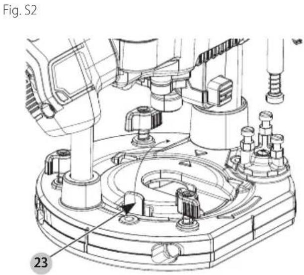
Dust Cap (Fig. S1–S3)
A dust cap 8 comes provided with your router designed to reduce airborne dust by directing dust and debris away from the user.
To attach:
- Sit the router upright with the base plate 10 resting on a flat surface.
- Place the dust cap 8 through the opening of the base plate lining up the dust cap hinges 37 with the base plate hinge openings 41.
- Rotate the dust cap down flush with the base plate until the dust cap tab 23 clicks, locking it into place (Fig. S1).
To remove: - Push on the dust cap tab 23 to unlock (Fig. S2).
- Rotate up toward the hinges and remove dust cap from the base plate opening.
NOTE: Always keep the dust cap clean and in place.
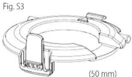
NOTE: This tool comes with an optional larger dust cap (50 mm) (Fig. S3)
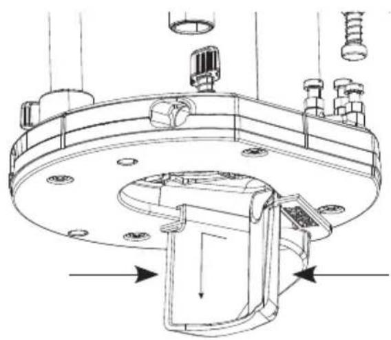
Chip Collector Adaptor for Dust Extraction (Fig. R1, R2)
Your tool comes with a chip collector adaptor for edge-cutting, designed to effectively divert dust and chips to the vacuum.
To attach:
- Slide the chip collector 33 into the underside of the base plate 10 until you hear a click (Fig.R1).
To remove:
- Squeeze both sides of the chip collector adaptor while sliding away from the base plate and then pulling down (Fig. R2).
MAINTENANCE
WARNING: To reduce the risk of serious personal injury, turn unit off and remove the battery pack before making any adjustments or removing/installing attachments or accessories. An accidental start-up can cause injury.
Your DEWALT power tool has been designed to operate over a long period of time with a minimum of maintenance. Continuous satisfactory operation depends upon proper tool care and regular cleaning.
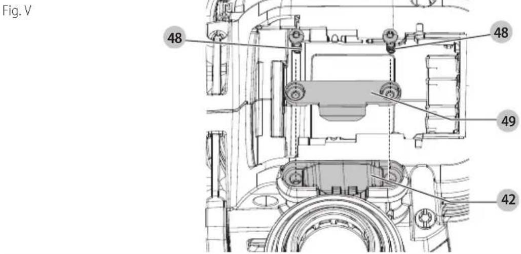
Tool Connect™ Chip (Fig. V)
WARNING: To reduce the risk of serious personal injury, turn unit off and remove the battery pack before making any adjustments or removing/installing attachments or accessories. An accidental start-up can cause injury.
Your tool is Tool Connect ^™ Chip ready and has a location for installation of a Tool Connect ^™ Chip.
Tool Connect™ Chip is an optional application for your smart device (such as a smart phone or tablet) that connects the device to utilize the mobile application for inventory management functions.
Refer to Tool Connect™ Chip Instruction Sheet for more information.
Installing the Tool Connect™ Chip
- Remove the retaining screws 48 that hold the Tool Connect™ Chip protective cover 49 into the tool.
- Remove the protective cover and insert the Tool Connect™ Chip into the empty pocket 42.
- Ensure that the Tool Connect™ Chip is flush with the housing. Secure it with the retaining screws and tighten the screws.
- Refer to Tool Connect™ Chip Instruction Sheet for further instructions.
Cleaning (Fig. 0)
WARNING: Blow dirt and dust out of all air vents with dry air at least once a week. To minimize the risk of eye injury, always wear ANSI Z87.1 approved eye protection and an approved dust mask when performing this procedure.
WARNING: Never use solvents or other harsh chemicals for cleaning the non-metallic parts of the tool. These chemicals may weaken the plastic materials used in these parts. Use a cloth dampened only with water and mild soap. Never let any liquid get inside the tool; never immerse any part of the tool into a liquid.
For better plunge sliding movement, frequently clean the plunge rods 36 of dust or debris with a DRY cloth only. If the plunging movement is not moving as smooth as desired, lubricate the plunge rods with a dry Teflon™ lubricant.
Accessories
WARNING: Since accessories, other than those offered by DEWALT, have not been tested with this product, use of such accessories with this product could be hazardous. To reduce the risk of injury, only DEWALT recommended accessories should be used with this product.
Recommended accessories for use with your product are available at extra cost from your local dealer or authorized service center. If you need assistance in locating any accessory, please contact DEWALT. Call 1-800-4-DEWALT (1-800-433-9258) or visit our website: www.dewalt.com.
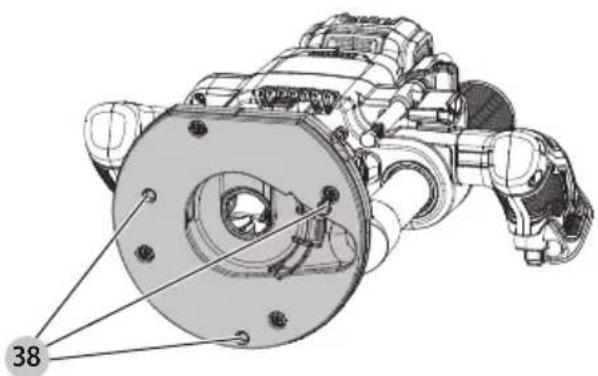
Base Mounting Points for Accessories (Fig. N)
This router has three threaded holes 38 built into the base that allows it to attach to other accessories.
Repairs
The charger and batteries are not serviceable. There are no serviceable parts inside the charger or battery pack.
WARNING: To assure product SAFETY and RELIABILITY, repairs, maintenance and adjustment (including brush inspection and replacement, when applicable) should be performed by a factory service center or an authorized service center. Always use identical replacement parts.
Register Online
Thank you for your purchase. Register your product now for:
- WARRANTY SERVICE: Registering your product will help you obtain more efficient warranty service in case there is a problem with your product.
- CONFIRMATION OF OWNERSHIP: In case of an insurance loss, such as fire, flood or theft, your registration of ownership will serve as your proof of purchase.
- FOR YOUR SAFETY: Registering your product will allow us to contact you in the unlikely event a safety notification is required under the Federal Consumer Safety Act.
Register online at www.dewalt.com/account-login.
Three-Year Limited Warranty
For warranty terms, go to www.dewalt.com/support/warranty.
To request a written copy of the warranty terms, contact: Customer Service at DEWALT Industrial Tool Co., 701 East Joppa Road, Towson, MD 21286 or call 1-800-4-DEWALT (1-800-433-9258).
LATIN AMERICA: This warranty does not apply to products sold in Latin America. For products sold in Latin America, see country-specific warranty information contained in the packaging, call the local company or see website for warranty information.
FREE WARNING LABEL REPLACEMENT: If your warning labels become illegible or are missing, call 1-800-4-DEWALT (1-800-433-9258) for a free replacement.
natural_image
Technical line drawing of a mechanical component with no visible text or symbolsnatural_image
Technical line drawing of a mechanical component with no visible text or symbolsEje Central Lázaro Cárdenas No. 18 - Local (55) 5588 9377 D, Col. Obrera
MERIDA, YUC
Calle 63 #459-A - Col. Centro (999) 928 5038
MONTERREY, N.L.
Av. Francisco I. Madero 831 Poniente - Col. (818) 375 23 13 Centro
PUEBLA, PUE
17 Norte #205 - Col. Centro (222) 246 3714
QUERETARO, QRO
Av. San Roque 274 - Col. San Gregorio (442) 2 17 63 14
SAN LUIS POTOSI, SLP
Col. Santa Fe Alvaro Obregon,
Ciudad de Mexico, Mexico.
C.P 01210
TEL(52)55 53267100
R.F.C.BDE8106261W7
Registro en Línea
JING: Use of any other battery packs may create a risk of injury and fire.

NOTE: DO NOT charge when the battery pack is below 40^ F ( 4.5^ C) or above 104^ F ( 40^ C). Do not store or use the tool and battery pack in locations where the temperature may reach or exceed 104^ F ( 40^ C).