
OFE 738 - Router METABO - Free user manual and instructions
Find the device manual for free OFE 738 METABO in PDF.
| Product type | Router |
| Brand | Metabo |
| Model | OFE 738 |
| No-load speed | 13,000 - 34,000 rpm (6 continuously adjustable levels) |
| Collet clamping diameters | 3 mm, 6 mm, 8 mm, 1/8" (3.18 mm), 1/4" (6.35 mm) |
| Maximum routing depth | Max stroke not specified, recommended max 6 mm per pass |
| Power supply | Alternating current, mains voltage (230 V typical) |
| Protection class | II (double insulation) |
| Electronics | VC (constant speed under load) |
| Overload protection | Yes (speed reduction or automatic shutdown) |
| Safety shutdown | Metabo S-automatic (shutdown in case of jamming or kickback) |
| Side fence | Included, adjustable with graduated scale |
| Chip extraction system | Adapter for vacuum cleaner, front or rear mounting |
| Workable materials | Wood, similar materials, plastics |
| Compatible accessories | Roller stop, circular guide, angle guide, intermediate plate, copy guides |
| Maintenance | Regular cleaning of ventilation slots and tool; disconnect before maintenance |
| Repairs | Entrust to an electrician; special Metabo mains cable |
| Weight | Approx. 5 kg (estimate) |
Frequently Asked Questions - OFE 738 METABO
User questions about OFE 738 METABO
0 question about this device. Answer the ones you know or ask your own.
Ask a new question about this device
Download the instructions for your Router in PDF format for free! Find your manual OFE 738 - METABO and take your electronic device back in hand. On this page are published all the documents necessary for the use of your device. OFE 738 by METABO.
USER MANUAL OFE 738 METABO
natural_image
Exterior view of a metalworking presser with adjustable handle and mounting base (no visible text or symbols)
natural_image
Close-up of a hand operating a mechanical presser with a tool, showing a numbered component (8) and an arrow indicating motion direction (no text or symbols beyond label)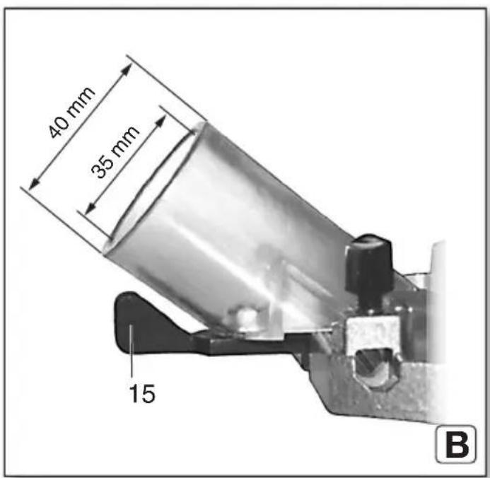
natural_image
Mechanical assembly diagram showing a cam mechanism and a cross-sectional view of a mechanical component (no text or symbols)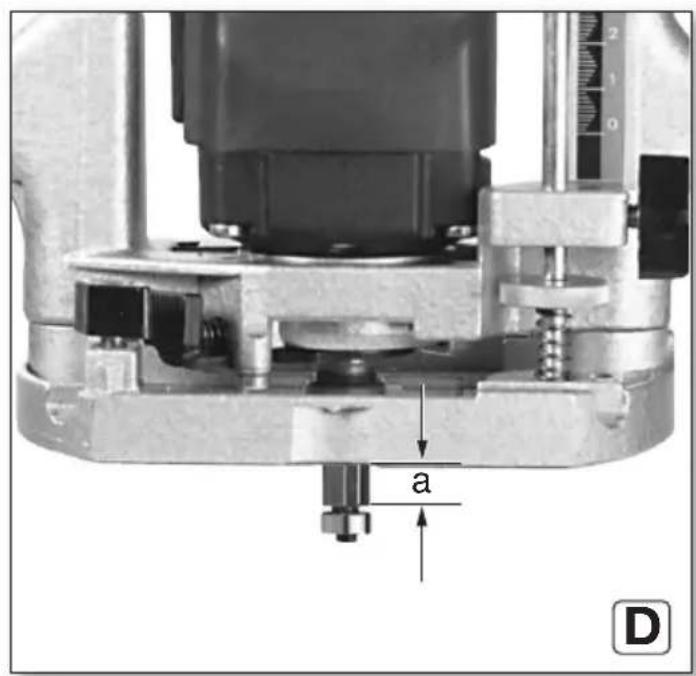
natural_image
Mechanical device with labeled part '7' and a hand holding a tool (no text or symbols on the device itself)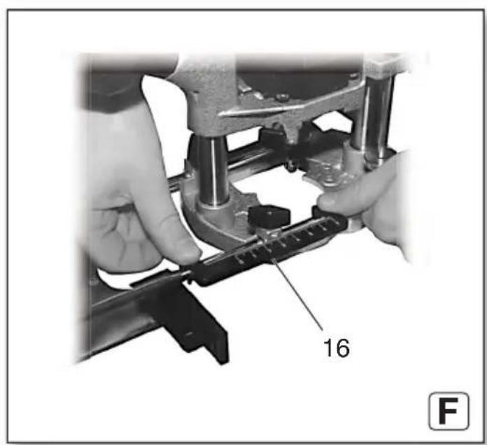
 | OFE 738 | |
| *1) Serial Number 00738.. | ||
| P_1 | W 710 | |
| P_2 | W 430 | |
| n_0 | 1/min (rpm) 13000 - 34000 | |
| n_1 | 1/min (rpm) 24000 | |
| H_max | mm (in) | 50 ( 1^30/_32 ) |
| d mm (in) | 8 ( ^5/_16 ) | |
| D_max | mm (in) 25 (1) | |
| m | k | g (I |
| a_h/K_h | m/s ^2 | 6 / 1,5 |
| L_pA/K_pA | dB(A) 83,2 / 3 | |
| L_WA/K_WA | dB(A) 94,2 / 3 | |
CE ^2) 2014/30/EU, 2006/42/EC, 2011/65/EU ^3) EN 62841:2015, EN 62841-2-17:2017, EN IEC 63000:2018
2021-10-28, Bernd Fleischmann
natural_image
Close-up of a metalworking machine with hands operating it, no visible text or symbols on the machine itself.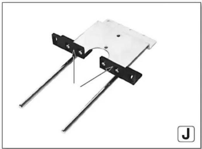
natural_image
Mechanical assembly diagram showing two metal rods with mounting holes and a curved component (no text or symbols)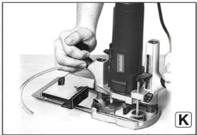
natural_image
Close-up of hands operating a power tool on an electronic circuit board (no visible text or symbols)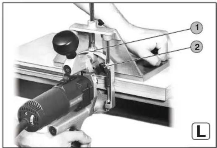
natural_image
Close-up of hands operating a metalworking presser machine with a metal bracket (no visible text or symbols)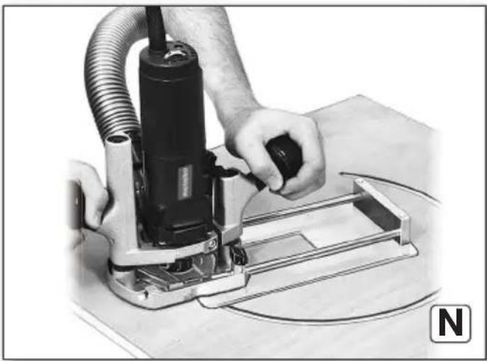
natural_image
Person operating a power tool with hoses and a metal frame, no visible text or symbolsOriginal instructions
1. Declaration of Conformity
We, being solely responsible, hereby declare: these routers, identified by type and serial number *1), meet all relevant requirements of directives *2) and standards *3). Technical documents for *4) - see page 4.
For UK only:
UK We as manufacturer and authorized person to CA compile the technical file, see *4) on page 3, hereby declare under sole responsibility that these routers, identified by type and serial number *1) on page 3, fulfill all relevant provisions of following UK Regulations S.I. 2016/1091, S.I. 2008/1597, S.I. 2012/3032 and Designated Standards EN 62841:2015, EN 62841-2-17:2017, EN IEC 63000:2018
2. Specified Conditions of Use
The router is suited for cutting wood, wood-like materials and plastic.
The user bears sole responsibility for any damage caused by inappropriate use.
Generally accepted accident prevention regulations and the enclosed safety information must be observed.
3. General Safety Information

For your own protection and for the protection of your power tool, pay attention to all parts of the text that are marked with this symbol!

WARNING – Read the operating instructions to reduce the risk of injury.

WARNING – Read all safety warnings, instructions, illustrations and
specifications provided with this power tool. Failure to follow all instructions listed below may result in electric shock, fire and/or serious injury.
Keep all safety instructions and information for future reference.
Always include these documents when passing on your power tool.
4. Special safety instructions
4.1 Safety instructions for routers
a) Hold the power tool by insulated gripping surfaces only, because the cutter may contact its own cord. Cutting a "live" wire may make exposed metalparts of the power tool "live" and could give the operator an electric shock.
b) Use clamps or another practical way to secure and support the workpiece to a stable platform. Holding the work by your hand or against
the body leaves it unstable and may lead to loss of control.
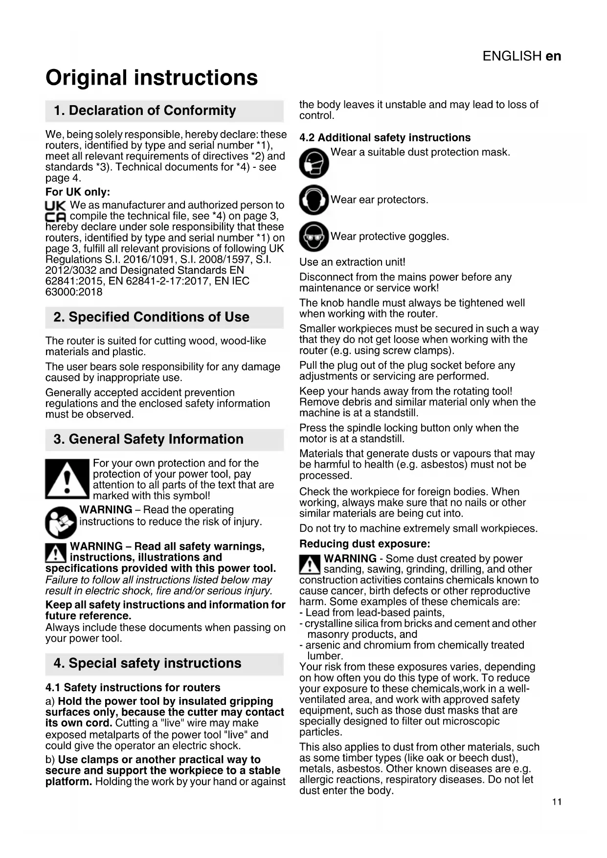
4.2 Additional safety instructions

Wear a suitable dust protection mask.

Wear ear protectors.

Wear protective goggles.
Use an extraction unit!
Disconnect from the mains power before any maintenance or service work!
The knob handle must always be tightened well when working with the router.
Smaller workpieces must be secured in such a way that they do not get loose when working with the router (e.g. using screw clamps).
Pull the plug out of the plug socket before any adjustments or servicing are performed.
Keep your hands away from the rotating tool! Remove debris and similar material only when the machine is at a standstill.
Press the spindle locking button only when the motor is at a standstill.
Materials that generate dusts or vapours that may be harmful to health (e.g. asbestos) must not be processed.
Check the workpiece for foreign bodies. When working, always make sure that no nails or other similar materials are being cut into.
Do not try to machine extremely small workpieces.
Reducing dust exposure:
WARNING - Some dust created by power sanding, sawing, grinding, drilling, and other construction activities contains chemicals known to cause cancer, birth defects or other reproductive harm. Some examples of these chemicals are:
- Lead from lead-based paints,
- crystalline silica from bricks and cement and other masonry products, and
- arsenic and chromium from chemically treated lumber.
Your risk from these exposures varies, depending on how often you do this type of work. To reduce your exposure to these chemicals, work in a well-ventilated area, and work with approved safety equipment, such as those dust masks that are specially designed to filter out microscopic particles.
This also applies to dust from other materials, such as some timber types (like oak or beech dust), metals, asbestos. Other known diseases are e.g. allergic reactions, respiratory diseases. Do not let dust enter the body.
ENGLISHen
Observe the relevant guidelines and national regulations for your material, staff, application and place of application (e.g. occupational health and safety regulations, disposal).
Collect the particles generated at the source, avoid deposits in the surrounding area.
Use suitable accessories for special work. In this way, fewer particles enter the environment in an uncontrolled manner.
Use a suitable extraction unit.
Reduce dust exposure with the following measures:
- do not direct the escaping particles and the exhaust air stream towards yourself or nearby persons or towards dust deposits,
- use an extraction unit and/or an air purifier,
- ensure good ventilation of the workplace and keep it clean using a vacuum cleaner. Sweeping or blowing stirs up dust.
- Vacuum or wash protective clothing. Do not blow, beat or brush protective gear.
5. Overview
See pages 2 and 3.
1 Speed adjustment wheel
2 Scale (cutting depth)
3 Knob handle (to hold and set the cutting depth)
4 Wing screw (cutting depth)
5 Pin (cutting depth)
6 Knurled screw (cutting depth)
7 Parallel stop
8 Connection piece (for chip extraction)
9 Collet chuck
10 Wing screws (parallel guide)
11 Collet chuck nut
12 Spindle locking button (to lock the milling spindle)
13 Knob handle (to hold)
14 Slide switch
15 Locking lever (extraction nozzle)
16 Scale (parallel guide)
17 Arrow mark
6. Initial Operation, Setting

Before commissioning, check that the rated mains voltage and mains frequency stated on type plate match your power supply.

Always install an RCD with a maximum trip current of 30 mA upstream.

Pull the plug out of the plug socket before any adjustments or servicing are performed.
6.1 Inserting the accessory

The high speed of the router requires high-quality tools (HSS or carbide).

Only use accessories that are suited for a speed of 34000 1/min.

Only use accessories the shaft diameter of which matches the collet bore of the collet k. Collet chucks see Chapter on Accessories.

The collet chuck nut may only be tightened by hand if no accessories are used.
- Unplug power cable;
- Locking the milling spindle: Push spindle locking button (12) and keep pressed.
- Turn the collet chuck nut (11) until the slider with the recess sits on the flats of the spindle.
- Insert the tool with the full length of the shank in the collet chuck (9).
- Firmly tighten the collet chuck nut (11) using a 19 mm open-end wrench.
- Release the spindle locking button (12).
6.2 Adjusting the cutting depth

Clean and safe cutting is achieved with a maximum cutting depth of 6 mm.

When working with hard wood, regularly release the machine when idle to cool the r sufficiently.
- Loosen the knob handle (3) (in anti-clockwise direction) and guide the motor part downwards until the milling cutter sits on the workpiece.
- Subsequently tighten the knob handle (3) again (turn in clockwise direction).
- Release the wing (4) screw.
- Guide the pin (5) downwards until it rests on the knurled screw (6).
- Pay attention to the scale (2), push the pin (5) upwards and roughly set the desired cutting depth at the scale (2).
- Retighten the wing screw (4).
- Fine adjustment using the knurled screw (6): 1 turn of the knurled screw corresponds to a change in cutting depth of about 1 mm.
6.3 Setting speed
The speed can be set via the thumb-wheel (1) and is infinitely variable.
The VC electronics keep the speed almost constant between idle and nominal load. This eliminates the need for manual readjustment.
Speeds when idle:
Stage 1....13000 1/min
Stage 2....18000 1/min
Stage 3....23000 1/min
Stage 4....27000 1/min
Stage 5....30500 1/min
Stage 6....34000 1/min
6.4 Attach the chip extraction
See page 2, fig. A+B.
- When using an extraction unit, the connection piece (8) is inserted from the front or rear into the base plate of the router.
- Slide the recess in the plate of the connection piece below the nose of the base plate (front or rear).
- Press the connection piece with a little pressure against the base plate.
- Lock the fixing lever (15) below the extraction nozzle in 90° position to the base plate.
- To extract the saw chips, connect a suitable extraction unit with suction hose to the connection piece.
7. Use
7.1 Switching on and off
Switching on: push the slide switch (14) downwards.
Switching off: press onto the top part of the slide switch (14).

Avoid inadvertent starts: always switch the tool off when the plug is removed from the socket or if there has been a power cut.
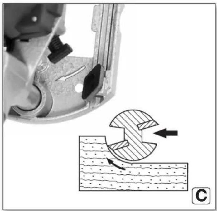
7.2 Working Directions
Machine use
Guide the connection cable in such a way that it does not hinder your work (e.g. sling over your shoulder).
Hold the router firmly on both knob handles.
Feed direction
See page 3, fig. C.
Always work in the opposite direction. Always push the router forwards as shown.
The direction of rotation of the router is indicated by arrows on the base plate of the router.
Guide the machine evenly at a speed suitable for the material being processed.
7.3 Putting down after use
After finishing the milling process, switch off the router and loosen the knob handle (3). Then the motor is pressed upwards by the springs in the columns and the machine can be put down.
7.4 Special working methods:
Milling from the workpiece edge.
See page 3, fig. D.
- Use routers with a thrust ring
- Release the knob handle (3) and lower the motor part of the switched-on router to the desired milling depth (a).
- To fix the milling depth, tighten the knob handle (3) and push the machine forward.
Milling along a strip attached to the workpiece / milling along a straight marking
- Attach a strip on the workpiece and guide the router with a straight edge of the foot plate along the strip. (Always use the same edge.)
Mill grooves and fillets from the centre of the workpiece
- Release the knob handle (3) and lower the motor part of the switched-on router to the desired milling depth.
- To fix the milling depth, tighten the knob handle (3) and push the machine forward.
Profile milling
- When working with profile cutters, first remove a larger chip and then a smaller chip.
- The feed rate must not be too low, otherwise the wood will scorch and the cutter will become prematurely blunt.
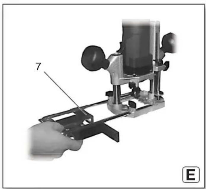
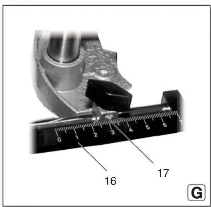
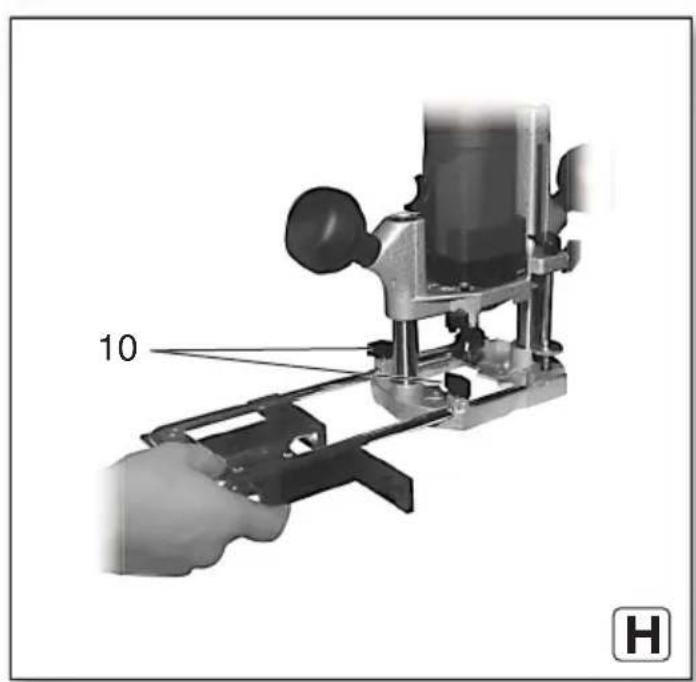
Sawing with parallel guide (E-H)
- Fig.: E: Push the parallel guide (7) into the grooves on the base plate.
- Fig.: F: Insert the scale (16) as shown.
- Fig.: G: Changes in distance between the stop angle and the cutter can be read off the scale (16) using the arrow marks (17).
- Fig.: H: Tighten wing screw (10).
8. Cleaning, Maintenance
Dust deposits must be regularly removed from the machine. This includes vacuum cleaning the ventilation louvres on the motor.
9. Troubleshooting
- Overload protection: There is a MAJOR reduction in load speed. The motor temperature is too high! Allow the machine to run at idle speed until it has cooled down.
- Overload protection: There is a SLIGHT reduction in load speed. The machine is overloaded. Reduce the load before continuing to work.
- Metabo S-automatic safety shutdown: The machine was SWITCHED OFF automatically. If the slew rate of the current is too high (for example, if the machine suddenly seizes or kickback occurs), the machine switches off. Switch off the machine using the slide switch (14). Switch it on again and continue to work as normal. Try to prevent the machine from seizing.
- Restart protection: The machine does not start. Restart protection is active. If the mains plug is inserted with the machine switched on or if the power supply is restored following an interruption, the machine does not start up. Switch the machine off and back on again.
10. Accessories
Use only genuine Metabo accessories.
Use only accessories that fulfil the requirements and specifications listed in these operating instructions.
Collet chucks (including nut): collet bore order no.
ø 3 mm ......31 947
ø 1/8" (3.18 mm) ......31 948
ø 6 mm....31 945
ø 1/4" (6.35 mm) ......31 949
ø 8 mm....31 946.
For the complete range of accessories, see www.metabo.com or the main catalogue.
10.1 Working with accessories
30 360 Stop with guide bearings (see page 4, fig. I+J)
Fig. H: The stop with guide bearings is used for cutting along a curved edge.
- (see fig. J) remove plastic strip. Attach the stop with guide bearings to the top of the parallel guide/rip fence for milling thin workpieces and to
ENGLISHen
the bottom of the parallel guide/rip fence for milling thicker workpieces.
- The wing screws of the stop with guide bearings can (depending on the work to be carried out) be screwed into the middle and rear or the middle and front threaded hole of the stop with guide bearings through the holes of the parallel guide/rip fence.
31 504 Circular guide pin (see page 4, fig. K)
A circular guide pin can be attached to the parallel guide/rip fence for milling circular grooves, milling round openings, rounding of corners and similar work.
- For milling large radius circles, attach the circular guide pin to the rear hole using a wing screw. For small radii it can be attached to the front hole. Smallest possible diameter 160 mm.
- Make a small countersink on the workpiece and insert the guide pin with its tip into the countersink.
- The radius of the circle to be milled can be changed by moving the parallel guide/rip fence in the base plate of the router.
30 103 Mitre fence (see page 4, fig. L)
The mitre fence permits optimum guidance of the router, especially when working on the edge of workpieces (e.g. for cutting grooves for tongued edging strips).
- The distance of the cutter to the workpiece edge can be precisely adjusted with the knurled nut (1) of the mitre fence. The wing screws (2) on the base plate are loosened here. These are then screwed tight.
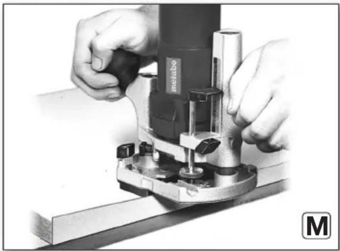
31 503 Intermediate plate (see page 4, fig. M)
Intermediate plate for trimming edges e.g. of protruding edging strips.
- Screw the intermediate plate to the underside of the router.
- Adjust the router in such a way that its face is flush with the underside of the intermediate plate.
31 505 Circular cutting guide (see page 4, fig. N)
For very precise circular cutting work, the circular cutting guide can be inserted in the base plate of the router.
-
The pin of the circular cutting guide can be screwed into the inner or outer hole of the circular cutting guide.
Largest possible circle diameter for external mounting: 480 mm Largest possible circle diameter for internal mounting: 350 mm -
The pin of the circular cutting guide can be inserted into a hole with matching diameter.
-
The radius of the circle to be milled can be changed by moving the circular cutting guide in the base plate of the router.
Template followers
For cutting letters etc. according to a template fixed on the workpiece.
A = outer diameter of the guide bush
B = for straight bits up to ∅
C = order no.
A
B
9 mm 6 mm 30105
11 mm 8 mm 30106
17 mm 14 mm 30118
24 mm 19 mm 30119
27 mm 22 mm 30120
30 mm 25 mm 30121
- Place the template follower onto the base plate of the router. The guide bush is pointing downwards.
- Subsequently screw in the two countersunk screws into the threaded holes of the template follower.
- The spaces in the template must not be narrower than the outside diameter of the guide bush in the template follower.
- If the lettering is to be wider than the cutter diameter, the spaces in the template must be made correspondingly wider. The router is then guided with the guide bush of the template follower first along one and then along the other edge of the template space.
11. Repairs

Repairs to electrical tools must only be carried out by qualified electricians!
A defective mains cable must be replaced only with a special, original mains cable from Metabo available from the Metabo service.
Contact your local Metabo representative if you have Metabo power tools requiring repairs. For addresses see www.metabo.com.
You can download a list of spare parts from www.metabo.com.
12. Environmental Protection
Observe national regulations on environmentally compatible disposal and on the recycling of disused machines, packaging and accessories.
Packaging materials must be disposed of according to their labelling in accordance with municipal guidelines. Further information can be found at www.metabo.com in the “Service” section.

Only for EU countries: never dispose of power tools in your household waste! According to European Directive 2012/19/EU
on Waste from Electric and Electronic Equipment and implementation in national law, used power tools must be collected separately and recycled in an environmentally-friendly manner.
13. Technical Specifications
Explanatory notes on the specifications on page 3. Changes due to technological progress reserved.
$$ P _ {1} \quad = \text { R a t e d i n p u t } $$
P_2 =Power output n_0 =Idle speed n_1 =Speed at rated load H_max =max. stroke height d =collet bore of the collet chuck D_max =max. permissible diameter of the cutter m =Weight without mains cable Measured values determined in conformity with EN 62841.
□ Machine in protection class II
\~ AC Power
The technical specifications quoted are subject to tolerances (in compliance with relevant valid standards).
Emission values These values mak
These values make it possible to assess the emissions from the power tool and to compare different power tools. The actual load may be higher or lower depending on operating conditions, the condition of the power tool or the accessories used. Please allow for breaks and periods when the load is lower for assessment purposes. Arrange protective measures for the user, such as organisational measures based on the adjusted estimates.
Vibration total value (vector sum of three directions) determined in accordance with EN 62841:
a_h =vibration emission value (Slot milling in MDF) K_h =uncertainty (vibration)
Typical A-effective perceived sound levels:
L_pA = sound pressure level
L_WA = acoustic power level
K_pA, K_WA = Uncertainty
The noise level can exceed 80 dB(A) during operation.

Wear ear protectors!
FRANÇAISfr
Notice originale
K_h =incertitude (vibration)
natural_image
Icon showing an open book and a recycling bin with a circular arrow (no text or symbols)Metabowerke GmbH
Metabo-Allee 1
72622 Nuertingen
Germany
www.metabo.com
metabo®
PROFESSIONAL POWER TOOL SOLUTIONS


- Original instructions
- Declaration of Conformity
- For UK only:
- Specified Conditions of Use
- General Safety Information
- Special safety instructions
- Safety instructions for routers
- Additional safety instructions
- Reducing dust exposure:
- ENGLISHen
- Overview
- Initial Operation, Setting
- Inserting the accessory
- Adjusting the cutting depth
- Setting speed
- Attach the chip extraction
- Use
- Switching on and off
- Working Directions
- Machine use
- Feed direction
- Putting down after use
- Special working methods:
- Milling from the workpiece edge.
- Milling along a strip attached to the workpiece / milling along a straight marking
- Mill grooves and fillets from the centre of the workpiece
- Profile milling
- Sawing with parallel guide (E-H)
- Cleaning, Maintenance
- Troubleshooting
- Accessories
- Working with accessories
- 360 Stop with guide bearings (see page 4, fig. I+J)
- 504 Circular guide pin (see page 4, fig. K)
- 103 Mitre fence (see page 4, fig. L)
- 503 Intermediate plate (see page 4, fig. M)
- 505 Circular cutting guide (see page 4, fig. N)
- Template followers
- A
- B
- Repairs
- Environmental Protection
- Technical Specifications
- Emission values These values mak
- FRANÇAISfr
- Notice originale
Brand : METABO
Model : OFE 738
Category : Router