LF 724 S - Router METABO - Free user manual and instructions
Find the device manual for free LF 724 S METABO in PDF.

| Product Type | Wood Planer (Router category) |
| Brand | Metabo |
| Model | LF 724 S |
| Supply Voltage | 230 V ~ (mains) |
| Frequency | 50/60 Hz |
| Rated Input Power (P1) | 1400 W (estimated) |
| Rated Output Power (P2) | Not specified |
| No-load Speed (n0) | Not specified |
| Rated Speed (n1) | Not specified |
| Weight | 5.5 kg (estimated) |
| Axial Cutting Depth | 0 – 0.3 mm |
| Planning Width | Not specified |
| Protection Class | II (double insulation) |
| Protection Device | Protection flaps, head locking |
| Suction Connection Diameter | 35 mm |
| Blade Type | Reversible blades (carbide tips) |
| Replacement Blade Ref. | 6.31720 (4 pieces) / 6.31660 (10 pieces) |
| Blade Fixing | Torx screws, tightening torque 5 Nm |
| Sound Pressure Level (LpA) | > 80 dB(A) |
| Vibration (ah) – softwood planing | Not specified |
| Main Functions | Planing, jointing, trimming, leveling |
| Maintenance and Cleaning | Cleaning blades, suction hose, sole |
| Safety | Emergency stop, anti-restart, mandatory use of personal protective equipment |
| Spare Parts and Repairability | Original Metabo parts, repair by qualified electrician |
| General Information | Manual 24 pages, available in several languages |
Frequently Asked Questions - LF 724 S METABO
User questions about LF 724 S METABO
0 question about this device. Answer the ones you know or ask your own.
Ask a new question about this device
Download the instructions for your Router in PDF format for free! Find your manual LF 724 S - METABO and take your electronic device back in hand. On this page are published all the documents necessary for the use of your device. LF 724 S by METABO.
USER MANUAL LF 724 S METABO
Operating instructions
1. Specified Use
The paint remover is suitable for the machining of painted and unpainted wooden surfaces.
The user bears sole responsibility for any damage caused by inappropriate use.
Generally accepted accident prevention regulations and the enclosed safety information must be observed.
2. General Safety Instructions

For your own protection and for the protection of your electrical tool, pay attention to all parts of the text that are marked with this symbol!

WARNING - Reading the operating instructions will reduce the risk of injury.
Pass on your electrical tool only together with these documents.
General Power Tool SafetyWarnings

WARNING - Read all safety warnings and
Instructions. Failure to follow the warnings
and instructions may result in electric shock, fire and/or serious injury.
Save all warnings and instructions for future reference! The term "power tool" in the warnings refers to your mains-operated (corded) power tool or battery-operated (cordless) power tool.
2.1 Work area safety
a) Keep work area clean and well lit. Cluttered or dark areas invite accidents.
b) Do not operate power tools in explosive atmospheres, such as in the presence of flammable liquids, gases or dust. Power tools create sparks which may ignite the dust or fumes.
c) Keep children and bystanders away while operating a power tool. Distractions can cause you to lose control.
2.2 Electrical safety
a) Power tool plugs must match the outlet. Never modify the plug in any way. Do not use any adapter plugs with earthed (grounded) power tools. Unmodified plugs and matching outlets will reduce risk of electric shock.
b) Avoid body contact with earthed or grounded surfaces, such as pipes, radiators, ranges and refrigerators. There is an increased risk of electric shock if your body is earthed or grounded.
c) Do not expose power tools to rain or wet conditions. Water entering a power tool will increase the risk of electric shock.
d) Do not abuse the cord. Never use the cord for carrying, pulling or unplugging the power
tool. Keep cord away from heat, oil, sharp edges or moving parts. Damaged or entangled cords increase the risk of electric shock.
e) When operating a power tool outdoors, use an extension cord suitable for outdoor use. Use of a cord suitable for outdoor use reduces the risk of electric shock.
f) If operating a power tool in a damp location is unavoidable, use a residual current device (RCD) protected supply. Use of an RCD reduces the risk of electric shock.
2.3 Personal safety
a) Stay alert, watch what you are doing and use common sense when operating a power tool. Do not use a power tool while you are tired or under the influence of drugs, alcohol or medication. A moment of inattention while operating power tools may result in serious personal injury.
b) Use personal protective equipment. Always wear eye protection. Protective equipment such as dust mask, non-skid safety shoes, hard hat, or hearing protection used for appropriate conditions will reduce personal injuries.
c) Prevent unintentional starting. Ensure the switch is in the off-position before connecting to power source and/or battery pack, picking up or carrying the tool. Carrying power tools with your finger on the switch or energising power tools that have the switch on invites accidents.
d) Remove any adjusting key or wrench before turning the power tool on. A wrench or a key left attached to a rotating part of the power tool may result in personal injury.
e) Do not overreach. Keep proper footing and balance at all times. This enables better control of the power tool in unexpected situations.
f) Dress properly. Do not wear loose clothing or jewellery. Keep your hair, clothing and gloves away from moving parts. Loose clothes, jewellery or long hair can be caught in moving parts.
g) If devices are provided for the connection of dust extraction and collection facilities, ensure these are connected and properly used. Use of dust collection can reduce dust-related hazards.
2.4 Power tool use and care
a) Do not force the power tool. Use the correct power tool for your application. The correct power tool will do the job better and safer at the rate for which it was designed.
b) Do not use the power tool if the switch does not turn it on and off. Any power tool that cannot be controlled with the switch is dangerous and must be repaired.
c) Disconnect the plug from the power source and/or the battery pack from the power tool before making any adjustments, changing accessories, or storing power tools. Such
preventive safety measures reduce the risk of starting the power tool accidentally.
d) Store idle power tools out of the reach of children and do not allow persons unfamiliar with the power tool or these instructions to operate the power tool. Power tools are dangerous in the hands of untrained users.
e) Maintain power tools. Check for misalignment or binding of moving parts, breakage of parts and any other condition that may affect the power tool's operation. If damaged, have the power tool repaired before use. Many accidents are caused by poorly maintained power tools.
f) Keep cutting tools sharp and clean. Properly maintained cutting tools with sharp cutting edges are less likely to bind and are easier to control.
g) Use the power tool, accessories and tool bits etc. in accordance with these instructions, taking into account the working conditions and the work to be performed. Use of the power tool for operations different from those intended could result in a hazardous situation.
2.5 Service
a) Have your power tool serviced by a qualified repair person using only identical replacement parts. This will ensure that the safety of the power tool is maintained.
3. Special Safety Instructions
Hold power tool by insulated gripping surfaces, because the cutter head may contact its own cord. Cutting accessory contacting a "live" wire may make exposed metal parts of the power tool "live" and shock the operator.
Wait until the cutter head is at a standstill before setting down the power tool. An exposed cutter head can get caught on the surface and lead to a loss of control and possible serious injury.
Do not place the device on hard surfaces to protect the reversible cutting plates.
Always wear personal protective equipment, safety goggles, ear protectors, protective gloves and heavy-duty footwear during work and for all setting, conversion and maintenance tasks!
Danger of injury from the sharp edges of the reversible blades. Pay attention to the rotating cutter head! Keep in mind that the motor and thus the cutter head of your paint remover continues to run after switching off the tool.
Avoid inadvertent starts: always switch the tool off when the plug is removed from the mains socket or if there has been a power cut.
Turn/replace blunt reversible blades in good time: Worn cutting edges of the reversible blades increase the risk of kickback and reduce the quality of the milling operation.
Turn/replace blunt reversible blades always in pairs.
Do not machine any workpiece surfaces that contain nails, screws or similar obstacles!
The workpiece must lay flat and be secured against slipping, e.g. using clamps.
Secure small workpieces. For example, clamp in a vice.
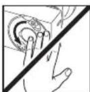
Opening the protective flaps:
Attention: Danger of injury from the sharp edges of the blades! Switch off the machine. The cutter head has to be idle!
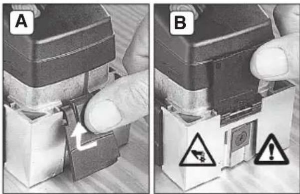
A: Open the protective flap as shown and
B: fold all the way upwards.
Protective flaps:
All protective flaps have to be closed during surface milling operations.
During peripheral milling (e.g. at folds) open only the protective flap pointing towards the workpiece.
High forces are released if the tool jams or catches. You must therefore always hold the machine with both hands using the handles provided, assume a safer stance and concentrate while working.
AdditionalWarnings:
WARNING
Some dust created by power sanding, sawing, grinding,
drilling, and other construction activities contains chemicals known to cause cancer, birth defects or other reproductive harm. Some examples of these chemicals are:
- Lead from lead-based paints,
- Crystalline silica from bricks and cement and other masonry products, and
- Arsenic and chromium from chemicallytreated lumber.
Your risk from these exposures varies, depending on how often you do this type of work. To reduce your exposure to these chemicals: work in a well ventilated area, and work with approved safety equipment, such as those dust masks that are specially designed to filter out microscopic particles.
SYMBOLS ON THE TOOLS:
Class II Construction
V..... volts
A . amperes
Hz ......... hertz
ENGLISHen
.../min .... revolutions per minute
rpm....... revolutions per minute
...alternating current
≈ ...alternating current /direct current
n . rated speed
4. Overview
See page 2.
1 Protective flap
2 Locking button
3 Additional handle
4 Sliding switch (0/1)
5 Handle
6 Extraction nozzle
7 Extraction connection piece (0 35 mm)
8 Graver
9 Multi-socket spanner
a Hexagon
b Torx
10 Planing base
11 Reversible blade
5. Commissioning
Before plugging in, check that the rated mains voltage and mains frequency, as stated on the rating label, match with your power supply.
Always install an RCD/GFCI with a max. trip current of 30mA upstream.
5.1 Attaching the additional handle
Always work with the additional handle (3) attached! Attach the auxiliary handle as shown.
6. Use
Always work with an extraction system to guarantee perfect machine operation.
Always guide the machine with both hands on the handles (3), (5) provided.
6.1 Switching On and Off the paint remover
Switching on
Lift paint remover so that the cutter head is free. Push the slide switch (4) forward.
I On
In continuous operation, the machine continues running if it is forced out of your hands. Therefore, always hold the machine with both hands using the handles provided, stand securely and concentrate.
Switching off
Lift paint remover so that the cutter head is free. Press the rear of the slide switch (4). The slide switch jumps back.
0 Off
Wait until the cutter head is at a standstill before setting down the machine. An exposed cutter head can get caught on the surface and lead to a loss of control and possible serious injury.
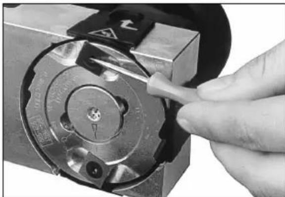
6.2 Locking the cutter head
Danger of injury from the sharp edges of the reversible blades. Lock the cutter head only when the cutter head is idle! Switch off paint remover and pull the mains plug from the socket!
Lay the paint remover on its side.
Press the locking button (2) up to the stop and keep pressed.
Simultaneously turn the cutter head using the hexagonal wrench (9-a) (any direction). Turn until the pressed locking button noticeably engages and the cutter head is locked.
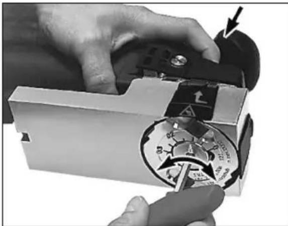
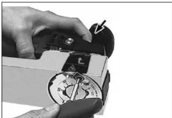
6.3 Setting the axial cutting depth
Danger of injury from the sharp edges of the reversible blades. Set the axial cutting depth only when the cutter head is idle! Switch off paint remover and pull the mains plug from the socket! Lock the cutter head and keep the locking button pressed.
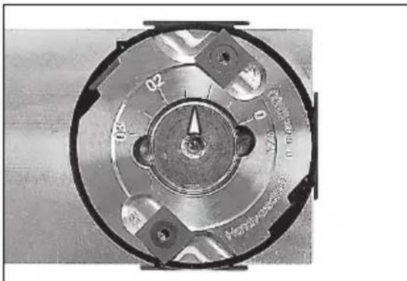
Set the desired cutting depth by turning the setting screw using a hexagonal wrench (9-a).
Possible cutting depths: 0-0.3 mm
Start with a small cutting depth and increase it gradually until you have reached the optimum setting for the workpiece to be processed.
Do not leave the hexagonal wrench in place!
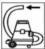
6.4 Attaching / Removing the extraction connection piece
Use a Metabo all-purpose vacuum cleaner for dust extraction purposes.
Attachment
Push the extraction connection piece (7) until it engages into the extraction nozzle (6).
Now the desired extraction unit can be connected to the extraction connection piece with the pipe diameter 35mm
Removal
Press the lip and simultaneously remove the extraction connection piece (7) from the extraction nozzle (6).
7. Tips and Tricks
7.1 Guiding the paint remover
Always use two hands to guide the paint remover backwards where possible over the surface of the workpiece being processed. When holding the paint remover down, ensure that the low pressure exerted is distributed evenly over the area of the planing base.
7.2 Presenting the tool to the edge of a workpiece
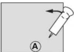
See diagram A: Hold the paint remover parallel with the surface of the workpiece. When presenting the tool, ensure that the planing base is in contact with the largest possible area of the surface (10).
7.3 Operation
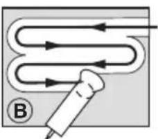
See diagram B: Guide the paint remover in such a way that the planing base (10) is always positioned on the surface that has not yet been processed. If you proceed as shown, a narrow section is left over.
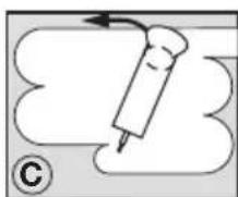
See figure C: You can remove this section by setting the cutting depth to 0mm (see section 6.3) and now always guide the planing base (10) over the processed surface.
7.4 Smoothing
Reduce the cutting depth to achieve a smooth surface finish.
8. Maintenance
Danger of injury from the sharp edges of the reversible blades. Effect maintenance work only when the cutter head is idle! Switch off paint remover and pull the mains plug from the socket!
Always wear personal protective equipment, safety goggles, ear protectors, protective gloves and heavy-duty footwear during work and for all setting, conversion and maintenance tasks!
8.1 Cleaning the reversible blades
Paint might build up under the cutting edges of the reversible blades. In this case, clean the edges of the reversible blades using the graver (8).
8.2 Turn/replace the reversible blades
Use original Metabo reversible blades only. Order no.: 6.31720 (4 pieces) Order no.: 6.31660 (10 pieces)
Blunt edges of the reversible blades increase the danger that the paint remover jams during the milling operation and kicks back. Therefore turn/ replace blunt reversible blades in good time!
If required, clean Torx of the reversible blades using a graver (8).
Axial reversible cutting plates:
Locking the cutter head.
Put the paint remover down and release locking button.
Remove hexagonal wrench (9-a) and refit (9-b, Torx).
Press the locking button (2) up to the stop and keep pressed.
Radial reversible cutting plates:
ENGLISHen
Open protective flap. Turn cutter head with multi-socket spanner until the reversible cutting blade is accessible.
Remove the screws of the reversible blades (11) with the Torx key(9-b). Loosen the reversible blade (11) with the gravel and clean the support surface of the reversible blades.
Insert the reversible blades (11) in such a way that the sharp edges are pointing in the direction of rotation.
If all edges are blunt, replace the reversible blade.
Always turn/replace both reversible blades!

Tighten reversed/new reversible blades with 5 Nm.

8.3 Cleaning the cutter head and sliding surface of the planing base
If required, clean the cutter head with agents suitable for cleaning aluminium (pH value between 4.5 and 8).
8.4 Cleaning the extraction nozzle
During the milling operation, chips can get stuck in the extraction nozzle (6) and clog the same.
Lodged chips can be loosened and removed through the cleaning slit in the extraction nozzle using the graver (8).
If required, remove the extraction nozzle (6). Remove the Phillips screws and pull out the extraction nozzle towards the rear. Clean extraction nozzle (6) and planing base (10).
9. Accessories
Use only genuine Metabo accessories.
Use only accessories which fulfil the requirements and specifications listed in these operating instructions.
For a complete range of accessories, see www.metabo.com or the catalogue.
10. Repairs
Repairs to electrical tools must be carried out by qualified electricians ONLY!
Contact your local Metabo representative if you have Metabo power tools requiring repairs. For addresses see www.metabo.com.
You can download a list of spare parts from www.metabo.com.
11. Environmental Protection
Observe national regulations on environmentally compatible disposal and on the recycling of disused machines, packaging and accessories.
Dispose of generated chips properly.
12. Technical Specifications
Explanatory notes on the specifications on page 3. Changes due to technological progress reserved.
P1 =rated input power
P2 =power output
no=no-load speed
n1 =on-load speed
m = weight
The technical specifications quoted are subject to tolerances (in compliance with the relevant valid standards).
A Emission values
These values make it possible to assess the emissions from the power tool and to compare different power tools. Depending on the operating conditions, the condition of the power tool or the accessories, the actual load may be higher or lower. For assessment purposes, please allow for breaks and periods when the load is lower. Based on the adjusted estimates, arrange protective measures for the user e.g. organisational measures.
Vibration total value (vector sum of three directions) determined in accordance with EN 60745:
a_h = Vibration emission value (planing soft wood)
K_h,SG = Uncertainty (vibration)
Typical A-effective perceived sound levels:
LpA =Sound-pressure level
During operation the noise level can exceed 80 dB(A).

Mode d'emploi
Kh =incertitude (vibration)