
HCP61310B - Basket BEKO - Free user manual and instructions
Find the device manual for free HCP61310B BEKO in PDF.
| Product type | Kitchen hood |
| Brand | Beko |
| Model | HCP61310B |
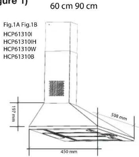
| Dimensions (W × D × H) | 598 mm × 450 mm × 197 mm |
| Power supply | 220-240 V ~ 50 Hz |
| Motor power | 90 W |
| Lighting power | 2 × 3 W (LED) |
| Maximum air flow | 395 m³/h (3 speeds) |
| Insulation class | Class II |
| Grease filter type | Washable aluminum filter |
| Charcoal filter type | Activated carbon filter (optional) |
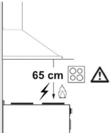
| Minimum distance from cooking surface | 65 cm |
| Exhaust duct diameter | 120 mm or 150 mm |
| Grease filter maintenance | Monthly cleaning (dishwasher safe) |
| Charcoal filter replacement | Every 3 months |
| Bulb type | LED spot 3 W, socket E14 |
| Operation | With external exhaust or recirculation with charcoal filter |
| Controls | Separate switches for light and motor (3 speeds) |
| Safety instructions | Disconnect before cleaning; do not use without filter; do not leave open flames |
Frequently Asked Questions - HCP61310B BEKO
User questions about HCP61310B BEKO
0 question about this device. Answer the ones you know or ask your own.
Ask a new question about this device
Download the instructions for your Basket in PDF format for free! Find your manual HCP61310B - BEKO and take your electronic device back in hand. On this page are published all the documents necessary for the use of your device. HCP61310B by BEKO.
USER MANUAL HCP61310B BEKO
natural_image
Simple line icon of a chimney emitting steam (no text or symbols)HCP61310I HCP91310I
HCP61310IH HCP91310W
HCP61310W HCP91310IH
HCP61310B
EN-BG-BS-CZ-DE-ET-FR-HR-HU-LT-LV-MK-NL-PL-PT-RO-SK-SL-SQ-SR
Please read this guide first!
Dear Customer,
Thank you for choosing a BEKO product. We would like you to achieve the optimal efficiency from this high quality product which has been manufactured with state of the art technology. Please make sure you read and understand this guide and supplementary documentation fully before use and keep it as a reference. Include this guide with the unit if you hand it over to someone else. Observe all warnings and information herein and follow the instructions.
Keep in mind that this user guide may apply to several product models. The guide clearly indicates any variations of different models.
Symbols and their meanings
These symbols are used throughout this guide:

Important information and recommendations regarding the use of the appliance.

CAUTION: Warnings on personal injury or property damage.
Electric shock warning.
Risk of fire warning.

Electric shock protection rating

This product has been manufactured at modern facilities respectful to the environment without harming nature.
CONTENTS
| ENGLISH | 04-12 |
| БЪЛГАРСКИ | 13-25 |
| BOSANSKI 26-36 | |
| ČESKY 37-47 | |
| DEUTSCH 48-60 | |
| EESTI 61-71 | |
| FRANÇAIS 72-82 | |
| HRVATSKI 83-93 | |
| MAGYAR 94-104 | |
| LIETUVIŲ K 105-115 | |
| LATVIĂN 116-126 | |
| MAKEДОНСКИ 127-139 | |
| NEDERLANDS 140-150 | |
| POLSKI 151-163 | |
| PORTUGUĖS 164-175 | |
| ROMÂNĂ 176-188 | |
| SLOVENSKÝ | 189-199 |
| SLOVENŠČINA | 200-210 |
| SHQIPTARE | 211-221 |
| СРПСКИ 222-236 |
1 Important safety and environmental instructions
1.1 General Safety
Important Safety Instructions Read Carefully And Keep For Future Reference This section contains safety instructions that will help protect from risk of fire, electric shock, exposure to leak microwave energy, personal injury or property damage. Failure to follow these instructions shall void any warranty.
- Beko products comply with the applicable safety standards; therefore, in case of any damage on the appliance or power cable, it should be repaired or replaced by the dealer, service center or a specialist and authorized service alike to avoid any danger. Faulty or unqualified repair work may be dangerous and cause risk to the user.
- This appliance is intended to be used in household and similar applications such as:
– Staff kitchen areas in shops, offices and other working environments;
- Farm houses
– By clients in hotels, and other residential type environments;
- Bed and Breakfast type environments.
- Operate the appliance for its intended purpose only as described in this manual.
- The manufacturer cannot be held liable for damages resulting from improper installation or misuse of the product.
• This appliance can be used by children aged from 8 years and above and persons
with reduced physical, sensory or mental capabilities or lack of experience and knowledge if they have been given supervision or instruction concerning use of the appliance in a safe way and understand the hazards involved.
- Children shall not be allowed play with the appliance. Cleaning and user maintenance shall not be made by children without supervision.
- The minimum distance between the supporting surface for the cooking vessels on the hob and the lowest part of your product must be at least 50 cm for electric hobs and 65 cm for gas hobs.
- If the instructions for installation for the gas hob specify a greater distance, this has to be taken into account.
- Make sure that your mains power supply complies with the information supplied on the rating plate of the appliance.
- Never use the appliance if the power cable or the appliance itself is damaged.
- Prevent damage to the power cable by not squeezing, bending, or rubbing it on sharp edges. Keep the power cable away from hot surfaces and naked flame.
- Use the appliance with a grounded outlet only.
WARNING: Do not connect the appliance to the mains until the installation is fully complete.
1 Important safety and environmental instructions
- Place the appliance in a way so that the plug is always accessible.
- Do not touch the lamps if they have operated for a long time. They can burn your hands since they will be hot.
- Follow the regulations set out by competent authorities on discharge of the exhaust air (this warning is not applicable for use without chimney).
- Operate your appliance after putting a pot, pan etc. on the hob. Otherwise, high heat may cause deformation in some parts of your product.
- Turn off the hob before taking the pot, pan etc. from it.
- Do not leave hot oil on the hob. Pans with hot oil may cause self combustion.
- Pay attention to your curtains and covers since oil may catch fire while cooking food such as fries.
- Grease filter must be replaced at least monthly. Carbon filter must be replaced at least every 3 months.
- Product shall be cleaned accordance with user manual. If cleaning was not carried out in accordance with user manual, there may be fire risk.
- Do not use non-fire-resistant filtering materials instead of the current filter.
-
Only use the original parts or parts recommended by the manufacturer.
-
Do not operate the product without the filter and do not remove the filters while the product is running.
- In the event of be started any flame, de-energize your product and cooking appliances.
- In the event of be started any flame, cover the flame and never use water to extinguish.
- Unplug the appliance before each cleaning and when the appliance is not in use.
- The negative pressure in the environment should not exceed 4 Pa (4 x 10 bar) while the hood for electric hob and appliances running on another type of energy but electricity operate simultaneously.
- In the environment where the appliance is being used, the exhaust of devices running on fuel oil or gas, such as room heater must be absolutely isolated or device must be hermetical type.
- When connecting the chimney, use pipes with a diameter of 120 or 150mm . Pipe connection must be as short as possible and have as few elbows as possible.
Danger of choking! Keep all the packaging materials away from children.
CAUTION: Accessible parts may become hot when used with cooking appliances.
- The product outlet must not be connected to air channels that include other smoke.
- The ventilation in the room may be insuf-
1 Important safety and environmental instructions
ficient when the hood for electric hob is used simultaneously with the devices operating on gas or other fuels (this may not apply to appliances that only discharge the air back into the room).
- Objects placed on the product may fall. Do not place any objects on the product.
- Do not flambe under the your product.
WARNING: Before installing the Hood, remove the protective films.
- Never leave high naked flames under the hood when it is in operation
- Deep fat fryers must be continuously monitored during use: overheated oil can burst into flames.
1.2 Compliance with the WEEE Directive and Disposing of the Waste Product:
This product complies with EU WEEE Directive (2012/19/EU). This product bears a classification symbol for waste electrical and electronic equipment (WEEE).
This symbol indicates that this product shall not be disposed with other household wastes at the end of its service life. Used device must be returned to official collection point for recycling of electrical and electronic devices. To find these collection systems please contact to your local authorities or retailer where the product was purchased. Each household performs important role
in recovering and recycling of old appliance. Appropriate disposal of used appliance helps prevent potential negative consequences for the environment and human health.
1.3 Compliance with RoHS Directive
The product you have purchased complies with EU RoHS Directive (2011/65/EU). It does not contain harmful and prohibited materials specified in the Directive.
1.4 Package Information
Packaging materials of the product are manufactured from recyclable materials in accordance with our National Environment Regulations. Do not dispose of the packaging materials together with the domestic or other wastes. Take them to the packaging material collection points designated by the local authorities.
2 General Appearance
2.1 Overview
(Figure 1)
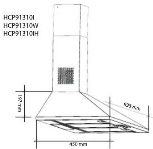
(Figure 2)
- Chimney
- Body
- Control Panel
- Aluminium Grease Filter
- Lighting
2.2 Technical Data
| Model HCP61310I - HCP61310IH - HCP61310W - HCP61310BHCP91310I - HCP91310W - HCP91310IH |
| Supply voltage 220-240V ~ 50 Hz |
| Lamp Power (W) 2 x 3 |
| Motor Power (W) 90 |
| Flow rate (m3/h) – 3. Level 395 |
| Insulation Class of Motor Class F |
| Insulation Class Class II |
3 Operation of the Appliance
3.1 Controlling the Appliance
0
1
2
3

0
1
To turn off the lamp, set the lamp switch ( ^20 ) to '0' position.
To turn on the lamp, set the lamp switch ( ) to '1' position.
To turn off the motor, set the motor switch (✗) to '0' position.
You can run the motor minimum at speed level 1 and maximum at speed level 3 depending on the cooking vapour intensity.
3.2 Efficient Use with Regard to Energy Saving
- When using your appliance, adjust the speed settings according to vapour and odour intensity, in order to save energy.
- Use low speeds (1-2) under normal conditions, and high speeds (3) in intense odour and vapour.
- The hood is equipped with lamps in order to illuminate the cooking area.
Using them for environmental lighting shall cause unnecessary energy expenditure and insufficient lighting.
3.3 Operating Instructions
- Your appliance contains a motor that has various speeds.
- For better performance, we recommend using low speeds under normal conditions and high speeds in cases of strong odours and intense vapour.
3 Operation of the Appliance
3.4 Replacement of Lamp
Make the electrical connections of the appliance. Your appliance is equipped with a 3 W spot LED lamp. For replacing the lamps, push downwards on the holder from its behind, turn it counter-clockwise, and take it out downwards. Apply the above operation in reverse to install new lamps (Figure 3).
(Figure 3)
| Bulb | 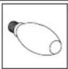 |
| Bulb Power (W) 3 | |
| Holder / Socket E14 | |
| Bulb Voltage (V) 220 | - 240 |
| Size (mm) 100 x 35 | |
| ILCOS Code DRBB/F | -3-220-240-E14-35/100 |
3.5 Operation with Flue Connection
• Vapour is extracted through the flue duct, which is fastened to the connection head on the
hood.
- The diameter of the flue duct must be the same as the connection ring. In horizontal settings, the pipe has to have a slight upward slope (around 10^ ) so that the air can exit the room easily.
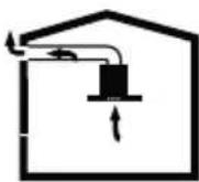
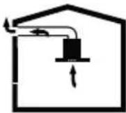
3.6 Operation without Flue Connection
• Air is filtered through the carbon filter and recirculated in the room. Carbon filter is
used when it is impossible to use a flue in the house.
- In flueless use, remove the flaps inside the flue adapter.
- Remove the aluminium grease filter. To install the carbon filter, fit the filter to the tabs by centring it on the plastic piece on both sides of the fan body. tighten it by turning right or left.
- Replace aluminium grease filter.
4 Cleaning and Maintenance

Before cleaning and maintenance, unplug the appliance or turn off the switch.
4.1 Cleaning of Aluminium Grease Filters
This filter retains the oil particles in the air. Aluminium grease filters may change colour as they are washed; this is normal and does not require replacing your filters.
natural_image
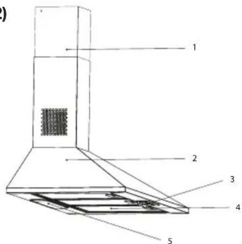
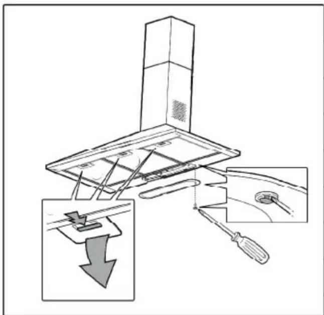
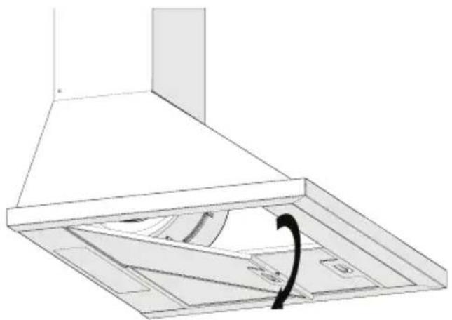
Technical line drawing of a ceiling structure with an arrow indicating rotation (no text or symbols)(Figure 4)
- Push the aluminium grease filter lock forward.
- Then pull it slightly down and pull it out (Figure 4). Otherwise, you can bend the filter. Wash and rinse aluminium grease filters with liquid detergent and replace aluminium filters to their sockets by by carrying out the steps specified above in reverse order. This filter retains the oil particles in the air.

You may also wash your aluminium grease filters in the dishwasher.

CAUTION
In case of normal use, clean your filter once in a month.
4.2 Replacement of Carbon Filters
Odour removing filters contain charcoal (Active carbon). Aluminium grease filters must be installed in the product, regardless of whether or not charcoal filters are used.
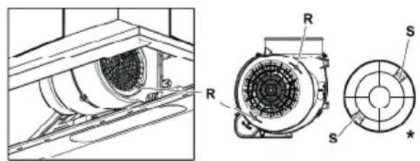
(Fig. 5)
- Remove the aluminium grease filters (Figure 4).
- Remove the filter by turning the pins from S level to R level clockwise. (Figure 5).
- Install the new filter by implementing the above procedure in reverse order.
• Install the aluminium grease filters.

CAUTION
Carbon filter shall never be washed.

CAUTION
Replace carbon filters once every 3 months.

CAUTION
You can obtain the charcoal filter from authorized service dealers.
5 Installation Of Appliance

WARNING!
Before installation, read safety information in the User Manual
WARNING!
Failure to install with screws and stabilizers in accordance with these instructions may result in electric shock.

NOTE
Please refer to page 235 for the installation guide
For the installation of the hood, please contact the nearest Authorized Service.
It is the customer's responsibility to prepare the location and electrical installation of the hood.
5.1 Position of the Appliance
(Figure 6)
- Distance between the cooker and the cooker hood must be considered prior to assembly. This distance should be 65 cm (Figure 6).
- Distance must be measured from the surface of grate for gas cookers, from surface of glass for electric cookers.
6 Troubleshooting
| Troubleshooting Root Cause Help | ||
| Appliance is not working. | Check your fuses. Fuse may be blown, inspect and restore it. | |
| Appliance is not working. | Check the electrical connection. Mains voltage shall be between 220 and 240 V. | |
| Appliance is not working. | Check the electrical connection. Check if other appliance in your kitchen operate. | |
| Illumination light does not operate. | Check the electrical connection. Mains voltage shall be between 220 and 240 V. | |
| Illumination light does not operate. | Inspect the lamp switch. Lamp switch shall be at "on" position. | |
| Illumination light does not operate. | Inspect the lamps. The lamps of the appliance shall illuminate. | |
| Air inlet of the appli-ance is inadequate. | Inspect the aluminium filter. Under normal operating condi-tions, aluminium grease filter shall be cleaned at least once in a month. | |
| Air inlet of the appli-ance is inadequate. | Check the air discharge flue. The air discharge flue shall be at "on" position. | |
| Air inlet of the appli-ance is inadequate. | Inspect the carbon filter. The filters of the appliances with carbon filters shall be re-placed once in every 3 months under normal conditions. | |
(Фигура 2)
(Фигура 3)
natural_image
Technical line drawing of a ceiling structure with a curved arrow indicating rotation (no text or symbols)(Фигура 4)
natural_image
Technical line drawing of a mechanical component with no visible text or symbols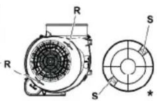
(Slika 2)
(Slika 3)
| Sijalica | 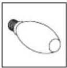 |
| Snaga sijalice (W) 3 | |
| Držač/utičnica E14 | |
| Napon sijalice (V) 220 - 240 | |
| Veličina (mm) 100 x | 35 |
| ILCOS kod DRBB/F-3-220-240-E14-35/100 | |
natural_image
Technical line drawing of a ceiling structure with an arrow indicating rotation (no text or symbols)(Slika 4)
- Gurnite bravu aluminjskog filtra za masnoću prema naprijed.
- Zatim je lagano povucite prema dolje i izvucite je (Slika 4). U suprotnom možete saviti filtar. Operite i isperite aluminijske filtre za ulje tečnim deterdžentom i vratite aluminijske filtre za ulje na njihova mjesta izvodeći gore navedene korake obrnutim redoslijedom. Ovaj filtar sakuplja čestice masnoće u vazduhu.

(Slika 5)
• Uklonite aluminijske filtre (Slika 4).
- Uklonite filter okretanjem igala iz nivoa S na nivo R u smjeru kazaljke na satu. (Slika 5).
- Ugradite novi filter primjenom gornjeg postupka obrnutim redom.
• Ugradite aluminjske filtere.

OPREZ
Karbonski filtar nikada se ne pere.

OPREZ
(Obrázek č. 2)
(Obrázek č. 3)
natural_image
Technical line drawing of a ceiling structure with internal components and a curved arrow indicating rotation (no text or symbols)(Obrázek č. 4)
(Obr. č. 5)
(Abbildung 2)
(Abbildung 3)
natural_image
Technical line drawing of a ceiling structure with a curved arrow indicating rotation (no text or symbols)(Abbildung 4)
natural_image
Technical line drawing of a mechanical component with a circular opening and mounting bracket (no text or symbols)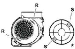
(Abb. 5)
(Joonis 2)
(Joonis 3)
| Pirn | 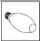 |
| Pirni võimsus (W) 3 | |
| Hoidja / Pesa E14 | |
| Pirni pinge (V) 220 - | 240 |
| Suurus (mm) 100 x | 35 |
| ILCOS kood DRBB/F | -3-220-240-E14-35/100 |
3.5 Kasutamine

korstnaühenduse korral
- Aur eemaldatakse suitsutoru kaudu, mis kinnitatakse
natural_image
Technical line drawing of a ceiling structure with ventilation duct and door (no text or symbols)(Joonis 4)
(Joonis 5)
(Figure 2)
(Figure 3)
natural_image
Technical line drawing of a ceiling structure with a curved arrow indicating rotation or movement (no text or symbols)(Figure 4)
(Fig. 5)
(Slika 2)
(Slika 3)
natural_image
Technical line drawing of a ceiling structure with ventilation duct and door (no text or symbols)(Slika 4)
- Gurnite blokadu aluminijskog filtra ulja prema naprijed.
- Zatim je lagano povucite prema dolje i van (slika 4). U protivnom možete saviti filtar. Operite i isperite aluminijske filtre ulja s tekućim deterdžentom i zamijenite aluminijske filtre u njihovim utičnicama u skladu s gore navedenim koracima samo obrnutim redoslijedom. Ovi filtri hvataju čestice ulja u zraku.

Aluminijske filtre možete prati u perilici suđa..

OPREZ
(SI. 5)
- Uklonite aluminijske filtre (slika 4). - Uklonite filtar okretanjem zatika s razine S na razinu R u smjeru kazaljke na satu. (Slika 5).
- Instalirajte novi filtar primjenom gornjeg postupka samo obrnutim redoslijedom.
• Instalirajte aluminijske filtre.

OPREZ
Ugljeni filtar nikad se ne smije prati.

OPREZ
Ugljani filtar zamijenite svaka 3 mjeseca.

OPREZ
(2. ábra)
(3. ábra)
natural_image
Technical line drawing of a ceiling structure with an arrow indicating rotation (no text or symbols)(4. ábra)
(5. ábra)
(2 pav.)
(3 pav.)
natural_image
Technical line drawing of a ceiling structure with an arrow indicating rotation (no text or symbols)(4 pav.)
(5 pav.)
(2. attēls)
(3. attēls)
natural_image
Technical line drawing of a ceiling structure with an arrow indicating rotation or movement (no text or symbols)(4. attēls)
(5. att.).
(Слика 3)
natural_image
Technical line drawing of a ceiling structure with a curved arrow indicating rotation (no text or symbols)(Слика 4)
natural_image
Technical line drawing of a mechanical component with internal components (no text or symbols)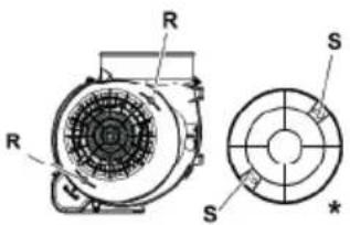
(Сл. 5)
(Afbeelding 2)
(Afbeelding 3)
| Lamp | 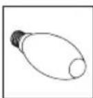 |
| Lampvermogen (W) | 3 |
| Houder / Stopcontact | E14 |
| Lampspanning (V) 2 | 20 - 240 |
| Afmeting(mm) 100 x 35 | |
| ILCOS Code DRBB/F | -3-220-240-E14-35/100 |
3.5 Bediening met
rookgasafvoer
natural_image
Technical line drawing of a ceiling structure with an arrow indicating rotation (no text or symbols)(Afbeelding 4)
(Afb. 5)
(Rys. 2)
(Rys. 3)
natural_image
Technical line drawing of a ceiling structure with a curved arrow indicating rotation or movement (no text or symbols)(Rys. 4)
natural_image
Technical line drawing of a mechanical component with a circular opening and mounting bracket (no text or symbols)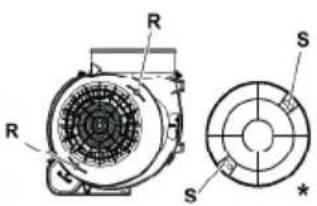
(Rys. 5)
(Figura 2)
(Figura 3)
natural_image
Technical line drawing of a kitchen chimney with ventilation duct and door panel (no text or symbols)(Figura 4)
(Fig. 5)
(Figura 2)
- Tub de evacuare
- Corp
- Panou de control
- Filtru metallic de ulei
- Sistem de iluminare
2.2 Date tehnice
| Model HCP61310I - HCP61310IH - HCP61310W - HCP61310B -HCP91310I - HCP91310W - HCP91310IH |
| Tensiune alimentare 220-240V ~ 50 Hz |
| Alimentare lampă (W) 2 x 3 |
| Putere motor (W) 90 |
| Debit (m3/h) – 3. Nivel 395 |
| Clasa de izolație motor Clasa F |
| Clasa de izolație Clasa II |
(Figura 3)
| Bec | 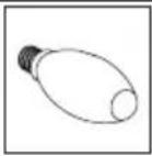 |
| Putere Bec (W) 3 | |
| Suport / priză E14 | |
| Tensiune bec (V) 220 - 240 | |
| Dimensiune (mm) 100 x 35 | |
| Cod ILCOS DRBB/F-3-220-240-E14-35/100 | |
natural_image
Technical line drawing of a ceiling structure with a curved arrow indicating rotation (no text or symbols)(Figura 4)
(Fig. 5)
(Obrázok č. 2)
(Obrázok
č. 3)
natural_image
Technical line drawing of a ceiling structure with a curved arrow indicating rotation (no text or symbols)(Obrázok č. 4)
natural_image
Technical line drawing of a mechanical component with a circular opening and mounting bracket (no text or symbols)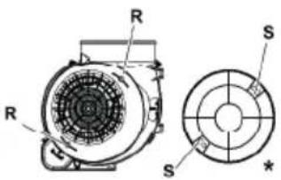
(Obr. č. 5)
(Slika 2)
(Slika 3)
| Žarnica | |
| Moč žarnice (W) 3 | |
| Držalo/vtičnica E14 | |
| Napetost žarnice (V) | 220–240 |
| Velikost (mm) 100 x | 35 |
| Koda ILCOS DRBB/F | -3-220-240-E14-35/100 |
3.5 Delovanje s priključkom dimne cevi

- Para se odvaja skozi dimni kanal, ki je pritrjen na priključno glavo nape.
natural_image
Technical line drawing of a ceiling structure with an arrow indicating rotation (no text or symbols)(Slika 4)
(Slika 5)
- Odstranite aluminijaste filtre (slika 4).
- Odstranite filter tako, da zatiče obrnete iz nivoja S v nivo R v smeri urnega kazalca. (Slika 5).
- Namestite novi filter z izvajanjem zgornjega postopka v obratnem vrstnem redu.
- Namestite aluminijaste filtre.

POZOR
Oglenega filtra nikoli ne umivajte.

POZOR
Ogleni filter zamenjate enkrat na tri mesece.
POZOR
(Figura 2)
- Tubi
- Trupi
- Paneli i kontrollit
- Filtri metalik i vajit
- Ndriçuesi i sobës
(Figura 3)
| Llamba | |
| Fuqia e llambës (W) | 3 |
| Mbajtësja / Foleja E14 | |
| Voltazhi i llambës (V) | 220 - 240 |
| Madhësia (mm) 100 | x 35 |
| Kodi ILCOS DRBB/F | 3-220-240-E14-35/100 |
natural_image
Technical line drawing of a ceiling structure with an arrow indicating rotation or movement (no text or symbols)(Figura 4)
(Fig. 5)
(Слика 2.)
(Слика 3.)
natural_image
Technical line drawing of a ceiling structure with ventilation duct and mounting bracket (no text or symbols)(Слика 4.)
natural_image
Technical line drawing of a mechanical component with a circular opening and internal structure (no text or symbols)