CSWL120CBK - Surveillance Camera NEDIS - Free user manual and instructions
Find the device manual for free CSWL120CBK NEDIS in PDF.



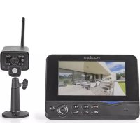
| Product type | Wireless surveillance camera with 7" LCD screen |
| Brand | Nedis |
| Model | CSWL120CBK |
| Image sensor (camera) | CMOS 1/4" |
| Lens (camera) | 2.0 mm |
| Viewing angle | 73° |
| Infrared illumination | 5 IR LEDs |
| Protection rating (camera) | IP54 |
| Microphone (camera) | Built-in, mono |
| Transmission frequency | 2.4 – 2.4835 GHz (digital) |
| Range indoor/outdoor | ±50 m / ±150 m |
| Power supply (camera) | 5 V DC, 400 mA |
| Weight (camera) | 287 g (cable included) |
| Screen | TFT LCD 7" |
| Screen resolution | 800 x 480 pixels |
| SD card | Up to 32 GB (not included) |
| Recording | Manual, scheduled, PIR |
| Video playback | AVI files |
| Power supply (screen) | 5 V DC, 650 mA |
| Dimensions (screen) | 214 x 157 x 26 mm |
| Weight (screen) | 488 g |
| Max. number of cameras | 4 |
| Menu languages | English, German, French, Dutch |
| Main functions | Night vision, PIR detection, alarm, quad mode, picture-in-picture |
| Maintenance and cleaning | Clean with a dry cloth only |
| Safety | Do not open, avoid water and moisture, extreme temperatures |
| Repairability | Repair by a qualified technician only |
Frequently Asked Questions - CSWL120CBK NEDIS
User questions about CSWL120CBK NEDIS
0 question about this device. Answer the ones you know or ask your own.
Ask a new question about this device
Download the instructions for your Surveillance Camera in PDF format for free! Find your manual CSWL120CBK - NEDIS and take your electronic device back in hand. On this page are published all the documents necessary for the use of your device. CSWL120CBK by NEDIS.
USER MANUAL CSWL120CBK NEDIS
natural_image
Two black-and-white photos: a security camera mounted on a stand with visible signal waves, and a digital TV displaying a surveillance camera with a smartphone (no text or symbols visible)Introduction:
Watch over your properties with this new 2.4 GHz digital wireless security camera system. The 7" LCD monitor can support up to 4 cameras and has an integrated digital video recorder.
The camera offers a very sharp and stable image with night vision and the technology used improves the image quality even further. The system uses digital wireless technology and is equipped with advanced frequency signal encryption capabilities, which reduce interference caused by other applications using the 2.4 GHz frequency band. This digital technology ensures your privacy and allows you to use it over an extra long distance. THE BEST THAT WIRELESS HAS TO OFFER.
The monitor and camera are paired by factory default already. When adding the additional camera CSWL1C20CBK (4 cameras max.) to the system, please refer to the section PAIRING for adding cameras.
- We recommend that you read this manual before installing/using the camera system.
- Keep this manual in a safe place for future reference.
Technical specifications:
Camera:
Transmitting frequency: 2.4-2.4835 GHz Digital
Modulation: 16QAM, QPSK, BPSK
Range: Indoor ±50 m, open area ±150 m (depending on local conditions)
Image chip: 1/4" CMOS
Lens: 2.0mm
View angle: 73°
Infrared illumination (LED): 5 M
Protection: IP54
Microphone: mono
Working temperature: -10°C \~ 50°C
Voltage: 5 V DC/400 mA
Dimensions: 132x64x57mm (without bracket)
Weight: 287 g (included cable)
LCD monitor:
Receiving frequency: 2.4-2.4835 GHz Digital
Channels: 4
Size: 7" TFT/LCD
Max. resolution: 800 RGB (H)* 480 (V) pixels
SD card: up to 32 GB (not included)
Video frame rate: 25 fps (max.) 10 fps (4x cameras)
Recording frame rate: 25 fps per channel
Video resolution: CIF/VGA
Video format: AVI
USB: 2.0
Menu language: English, German, French and Dutch
Video output level: 1 Vp-p/75 Ohm
Audio output level: 2Vrms@600ohm mono
Audio/video output
connector: 2.5mm jack (2.5mm cable to 3 x RCA included)
Range: Indoor ±50 m, open area ±150 m
(depending on local conditions)
Operating temperature: 0°C to +40°C
Voltage: 5 V DC/650 mA
Dimensions: 214x157x26 mm
Weight: 488 g
Safety precautions:
- Do not open the camera or monitor in the event of a malfunction. These products should only be opened by a qualified engineer.
- Do not submerge the camera in liquid.
- Do not expose the monitor to water or humidity.
- Do not expose the monitor or camera to high temperatures (see technical specifications).
- Do not install the system close to strong magnetic fields, such as a speaker. This may affect the quality.
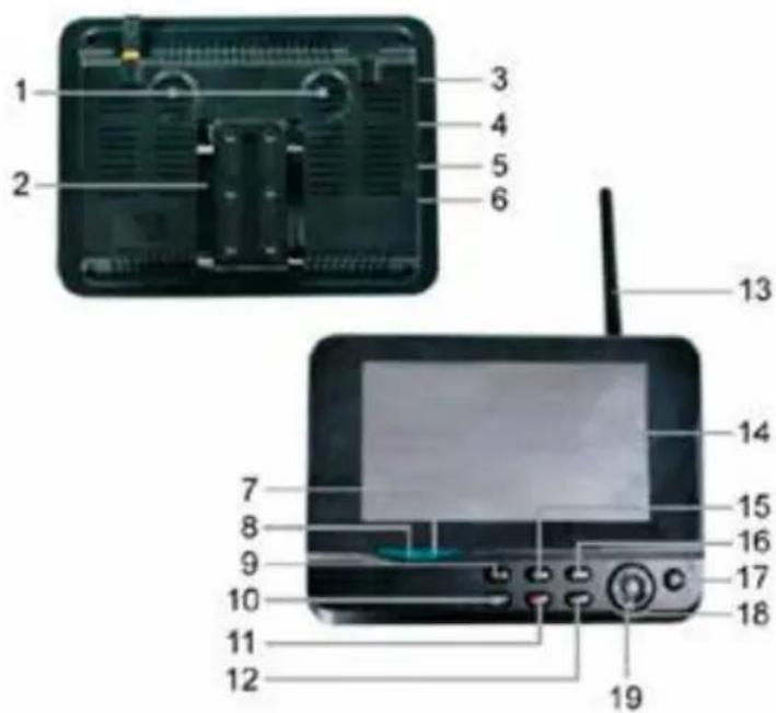
Product description:
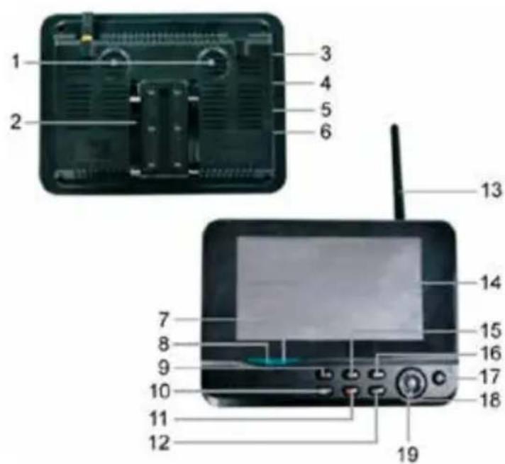
Camera:
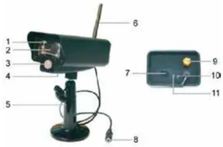
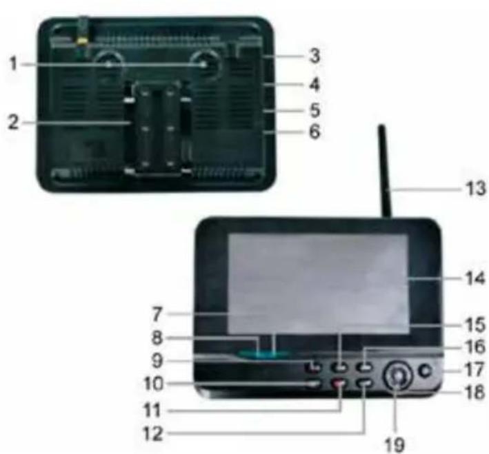
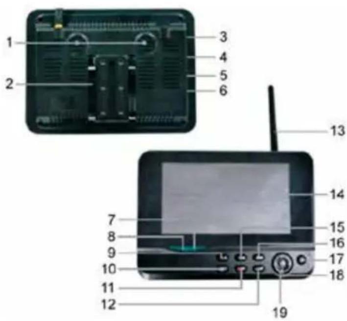
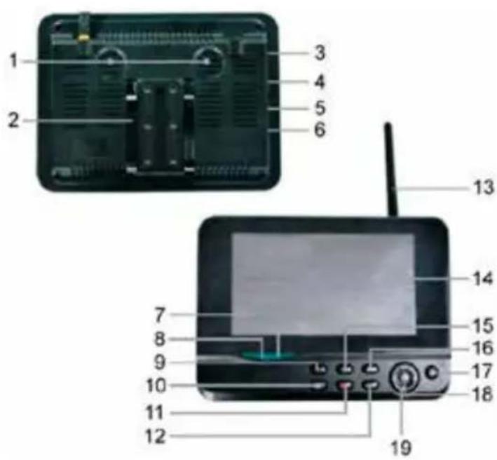
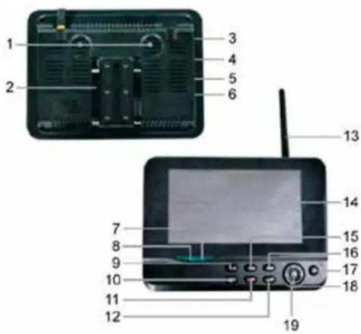
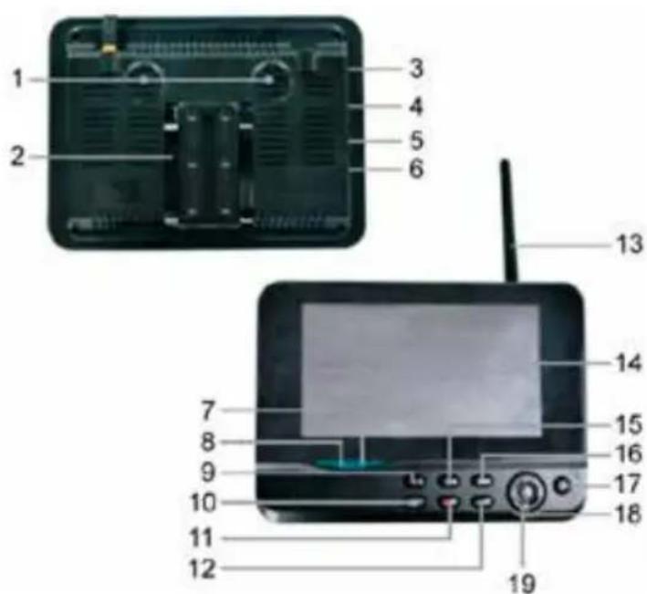
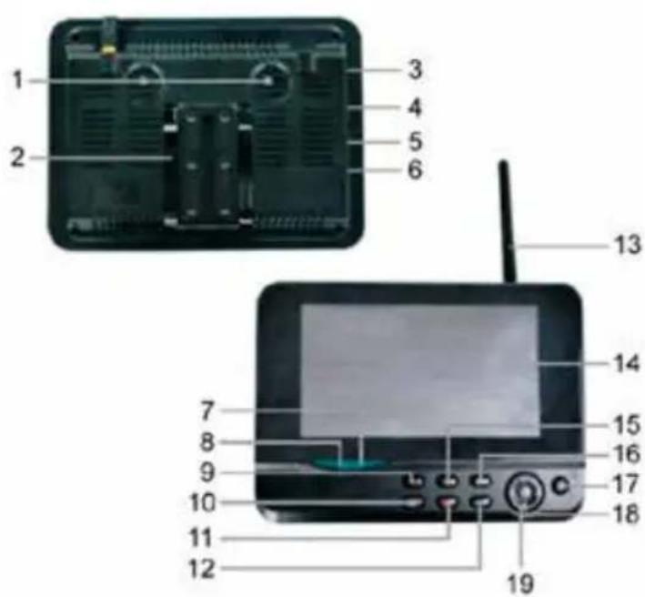
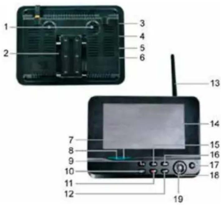
Monitor:
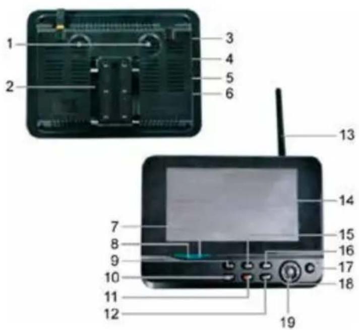
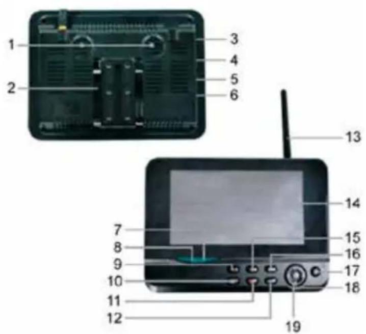
- Infrared LEDs
- Lens
- PIR infrared sensor
- Microphone
- Bracket
- Antenna
- Pair Button
- Power Input
- Antenna Socket
- Link Indicator
-
Power Indicator
-
Speaker
- Bracket
- USB Port
- SD Card Slot
- AV Output microUSB Network dongle slot Power Port
- Link Indicator
- Power Indicator
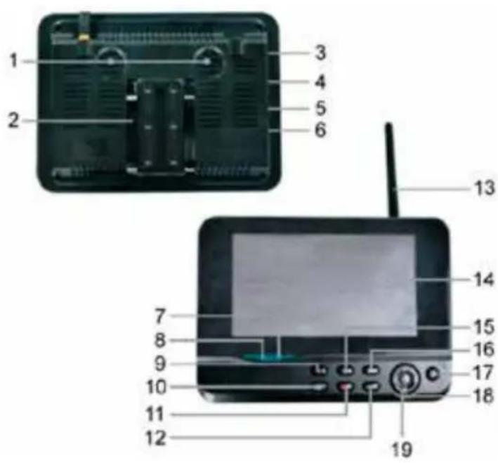
- Record/stop Video
- Quarter Display Button
- Delete file/LCD, TV Switch
- Menu
- Antenna
- 7" TFT-LCD
- Display Mode
- Playback Video
- Power on/off
- OK Button
- Navigate Button
Installation instructions:
Camera:
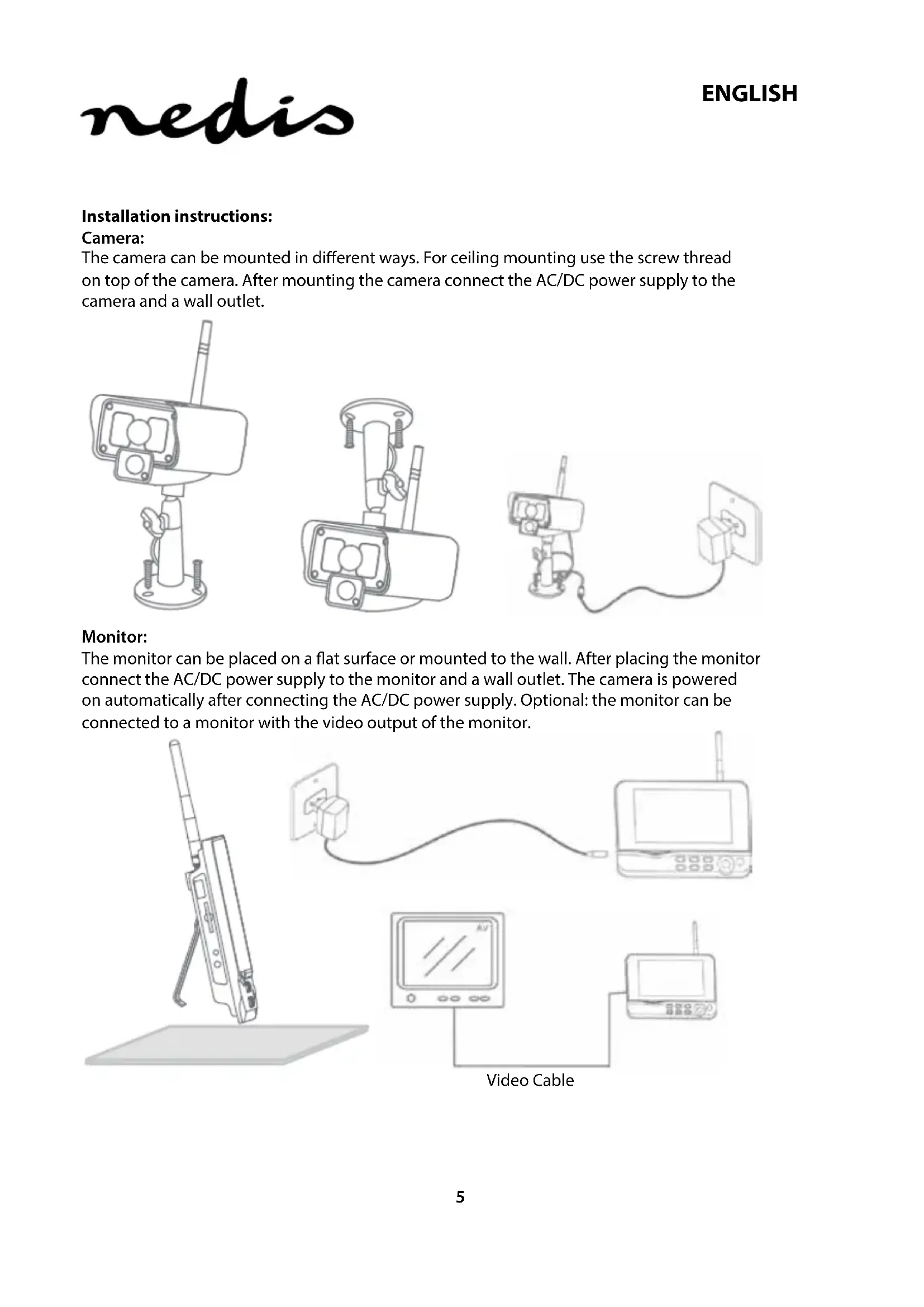
The camera can be mounted in different ways. For ceiling mounting use the screw thread on top of the camera. After mounting the camera connect the AC/DC power supply to the camera and a wall outlet.

natural_image
Line drawings of three different surveillance cameras with visible wiring and components (no text or symbols)Monitor:
The monitor can be placed on a flat surface or mounted to the wall. After placing the monitor connect the AC/DC power supply to the monitor and a wall outlet. The camera is powered on automatically after connecting the AC/DC power supply. Optional: the monitor can be connected to a monitor with the video output of the monitor.
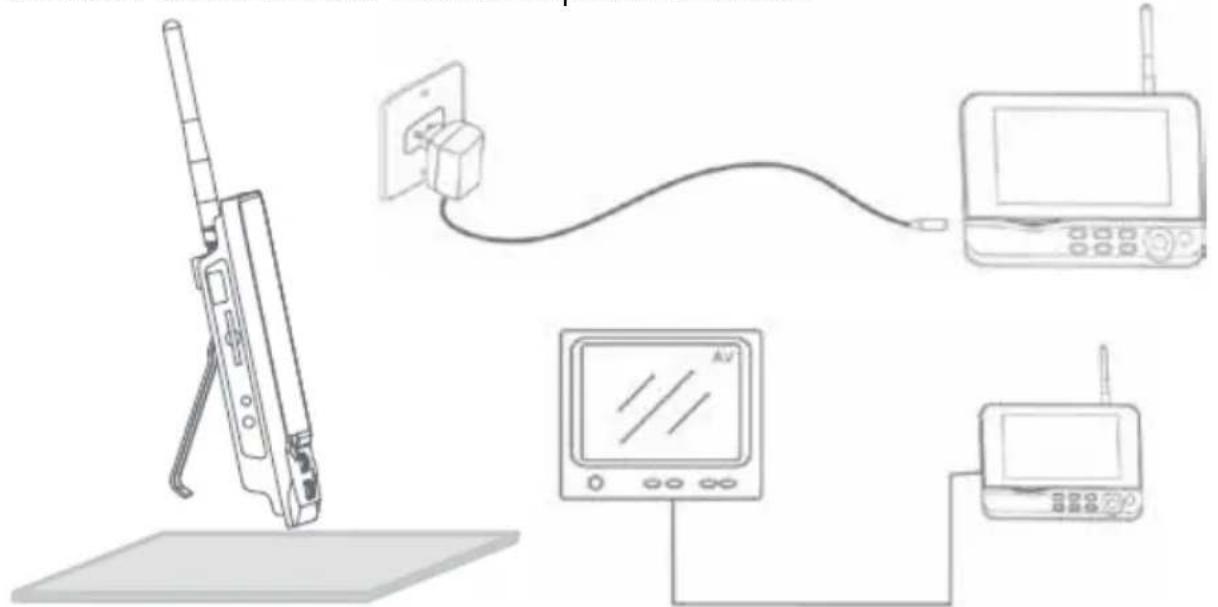
Video Cable
User instructions:
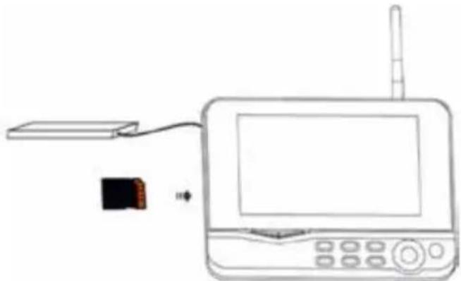
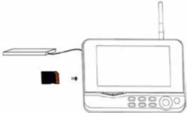
- Insert an SD card in the SD card slot of the monitor. Or connect an external hard disk drive to the USB port of the monitor.
natural_image
Line drawing of a device with a small electronic component connected to a screen and antenna (no text or symbols)-
Press the power on/off button for about 2 seconds to power on the monitor. The power indicator should light up and the picture appear.
-
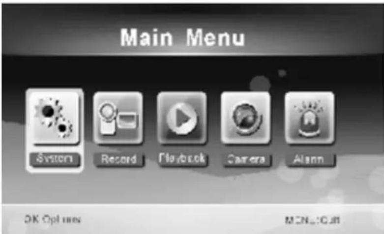
For systems settings press the menu button to open the main menu. The following screen should appear. Use the navigate, OK and menu buttons to navigate through the menu.
-
Only for CSWL120BK: Main menu is slightly different. Please refer for specific remote viewing functionality to the CSWL120BK QIG
System
- Press OK to enter the system settings. The system offers the following options:
Date/Time Set the time and date.
Language Set the language.
Record Mode Set to stop recording or overwrite the first video record when the storage medium is full.
Format SD/USB Set to format the storage medium.
Storage for Recording Set the storage medium.
Display Items Set to display RSSI, Time, SD/USB status and camera on the screen and the recorded video.
TV System Select a TV system (PAL for Europe).
System Information Shows the system information.
Scan Mode Period Set the cyclic display interval of the monitoring picture on the camera.
Mute Turns on/off the speaker on the monitor.
Load Default Reset the factory default settings.
Record Date/Time Set to display the current recording time and date on the recorded video.
Brightness Adjust brightness of the picture.
Volume Adjust the volume.
-
Select date/time with the navigate button and press OK to enter the date/time setting.
-
Press the left or right arrow button to select.
- Press the up or down arrow button to adjust.
- Press the OK button to confirm.
-
Press the MENU button to exit.
-
Select language with the navigate button and press OK to enter the language setting.
- Press the down or up arrow button to select language.
- Press the OK button to confirm and exit.
-
Select record mode with the navigate button and press OK to enter the record mode setting.
-
Press the up or down arrow button to select "Normal" or "Overwrite".
- Press the OK button to confirm and exit.
Remarks:
Normal: When the SD card or the mobile hard disk is full, the system stops recording automatically.
Overwrite: When the SD card or the mobile hard disk is full, the system automatically deletes the first video and reserves sufficient storage space to guarantee latest recording.
-
Select format SD/USB with the navigate button and press OK to enter the format SD/USB setting.
-
Press the up or down arrow button to select "Cancel", "SD Card" or "USB Device".
- Cancel: cancels formatting.
- SD Card: formats the SD card.
- USB Device: formats the external hard disk drive (if connected).
- Press the OK button to format.
- After formatting, the system shows "Format Successfully", indicating that formatting succeeds.
-
Press the OK button to confirm and exit.
-
Select storage for recording with the navigate button and press OK to enter the storage for recording setting.
- Press the up or down button to select "SD Card" or "USB Device".
- Press the OK button to confirm and exit.
-
Select display items with the navigate button and press OK to enter the display items setting.
-
Press the up or down arrow button to select.
- Click the OK button to confirm the display items in the picture.
- RSSI: Signal intensity icon
- SD USB status: Whether the SD card or mobile hard disk is inserted
-
Camera: Camera name icons
• After setting, press the MENU button to confirm and exit. -
Select TV system with the navigate button and press OK to enter the TV system setting.
- Press the up or down button to select NTSC or PAL (PAL for Europe).
- Press OK button to confirm and exit.
-
Select system information with the navigate button and press OK to enter the system information setting.
-
Press OK to see the information about the system.
-
Press the menu button to exit.
-
Select system upgrade with the navigate button and press OK to enter the system upgrade setting.
-
Press the up or down arrow button to select.
- Press OK.
-
Press the record/stop video button to confirm.
-
Select scan mode period with the navigate button and press OK to enter the scan mode period setting.
-
Press the up or down arrow button to select the period for scanning the connected cameras.
-
Press the OK button again to confirm and exit.
-
Select mute with the navigate button and press OK to enter the mute setting.
-
Press the up or down arrow button to select "On" or "Off".
-
Press the OK button again to confirm and exit.
-
Select load default with the navigate button and press OK to enter the load default setting.
-
Press the up or down button to select "Cancel" or "OK".
- Cancel: Cancels option default settings.
- OK: Resets default settings.
-
Press the OK button to confirm and exit.
-
Select brightness with the navigate button and press OK to enter the brightness setting.
-
Press the left or right arrow button to adjust the brightness.
-
Press the OK button to confirm and exit.
-
Select volume with the navigate button and press OK to enter the volume setting.
-
Press the left or right arrow button to adjust the volume.
- Press the OK button to confirm and exit.
Note: The volume can also be adjusted with the up or down arrow in live view monitoring.
- Press menu to return to the main menu.
Record
Press the right arrow button in the main menu to select the record settings and press OK. Timer Recording:
Set the recording start/stop time through the "Timer Recording" menu. The device automatically records according to the set start/stop time.
- Select timer recording with the navigate button and press OK to enter a new schedule setting.
- Press OK to enter the timer recording menu.
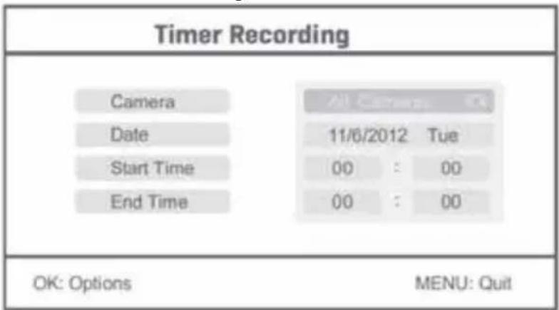
- Press the up or down arrow button to select.
- Press the left or right button to adjust.
-
Press the OK button to confirm and exit.
-
After setting, the device automatically records according to the set start/stop time.
- If you press the record/stop video button on the device during the recording process, set by timer recording, the recording stops.
Manual Recording:
- In live view monitoring, press the left and right arrow buttons to select the camera for video recording.
- Press the record/stop video button on the device. The recording icon is displayed on the screen, indicating that recording is starting.
- Press the button on the device again to stop recording.
PIR Recording:
PIR Recording: If there is human motion detected by any accessed camera, recording can be triggered.
-
Select PIR recording with the navigate button and press OK to enter the PIR recording setting.
-
Press the up or down button to select the camera.
- Press the left or right arrow button to select "On".
- Press the OK button to confirm and exit.
Note: when "Off" is set, the motion detection function is turned off. The infrared sensing distance of PIR is 5m. If the distance exceeds 5m, sensing may fail.
Playback
Press the right arrow button in the main menu to select the playback settings and press OK. Note: for playback functions it's necessary that an SD card is inserted or an external hard disk drive is connected.
The playback function can also be accessed in live view monitoring by pressing the playback video button.
- Press the up or down arrow button to select the folder.
- Press the OK button to confirm and enter.
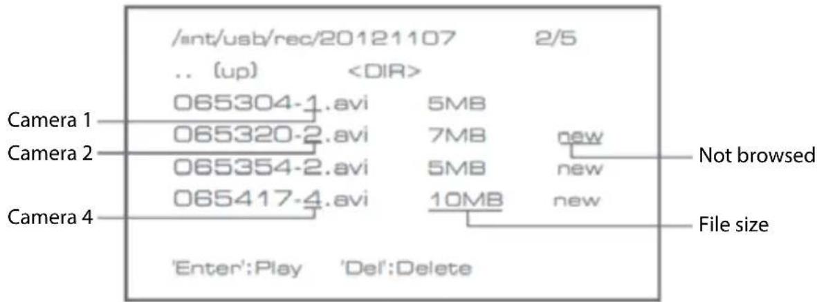
- Press the up or down arrow button to select the video file.
- Press the OK button for playback.
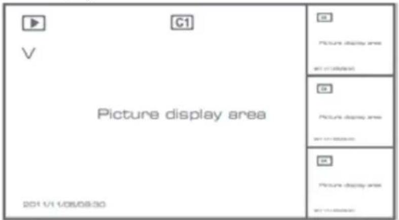
- Press the left or right arrow button to go backward/forward in fastforward.
- Press the OK button again to pause.
- Press the MENU button to quit the playback.
Delete video
In video playback mode, press the up or down arrow button to select the video or video folder to be deleted.
- Press the delete file/LCD button on the monitor to delete it.
Note: only an empty folder can be deleted as folder.
Camera
When adding the additional camera CSWL1C20CBK (max. 4) the camera needs to be paired to the system for the system to recognize the camera.
Press the right arrow button in the main menu to select the camera settings and press OK.
Pairing:
- Press OK to enter the pairing menu.
- Select the camera with the up and down arrow buttons.
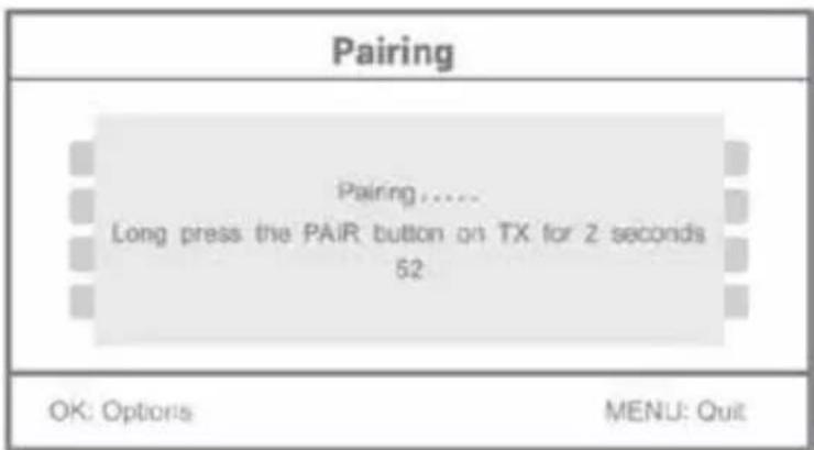
- Press OK, and the following screen will appear.

natural_image
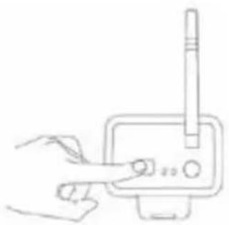
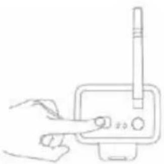
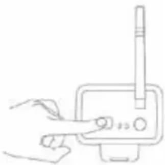
Hand holding a device with a pen inserted, no visible text or symbols- Press the pair button within 60 seconds for 2 seconds on the backside of the camera.
- After the successful pairing of the camera and the monitor, the monitor shows PAIRING OK.
- Press the menu button to return to the camera menu.
Note: if pairing fails, retry the above steps and be sure that the monitor and camera are not further away than 2 metres for pairing procedure.
Active:
- Select active with the down arrow button and press OK.
- Press the up or down arrow button to select the camera.
- Press the left or right arrow button to select "On" or "Off".
- Press the OK button to confirm and exit.
Note: only paired cameras can be set to active or not active. When a camera is set to off, it cannot be seen in live view, recorded, etc.
PIP setting:
Set the picture resolution size and recording quality.
- Select PIP setting with the up and down arrow buttons and press OK.
- Select the camera with the up and down arrow buttons and press OK. The following screen appears.
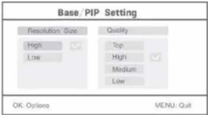
- Press the left or right arrow button to select "Resolution Size" or "Quality".
- Press the up or down arrow button to select "Top", "High", "Medium" or "Low".
- Press the OK button to adjust.
- Press the MENU button to confirm and exit.
Note: the high resolution size is VGA and low is CIF.
Alarm
When PIR detection is set to on, the system will give an alarm when motion is detected.
- Select alarm in the main menu and press OK.
- The screen shows PIR detection, press OK.
- Press "On" or "Off" with the up and down arrow button.
- Press OK to confirm and exit.
Live view:
Press the quarter display button to select the type of view.
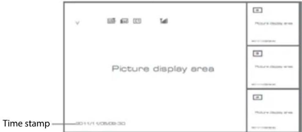
Picture in picture view
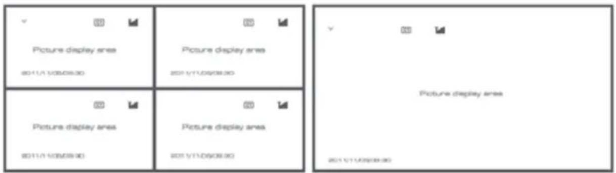
Quad view Full screen view
Note: use the left and right arrow button to select a camera.
Press the display mode button to enter cyclic mode view. Five cyclic intervals are available: 5s, 10s, 15s, 20s, and 30s and can be set under System > Scan Mode Period in the main menu.
 | Mobile hard disk inserted successfully |
 | SD card inserted successfully |
    | Camera name |
| [TXHS] | Current camera |
 | Recording status |
 | Signal intensity |
Maintenance:
Clean the product only with a dry cloth.
Do not use cleaning solvents or abrasives.
Warranty:
Any changes and/or modifications to the product will void the warranty. We cannot accept any liability for damage caused by incorrect use of this product.
Disclaimer:
Designs and specifications are subject to change without notice. All logos, brands and product names are trademarks or registered trademarks of their respective holders and are hereby recognized as such.
Disposal:

- This product is designated for separate collection at an appropriate collection point.
Do not dispose of this product with household waste.
- For more information, contact the retailer or the local authority responsible for waste management.
This product has been manufactured and supplied in compliance with all relevant regulations and directives, valid for all member states of the European Union. It also complies to all applicable specifications and regulations in the country of sales. Formal documentation is available upon request. This includes, but is not limited to: Declaration of Conformity (and product identity), Material Safety Data Sheet, product test report.
Please contact our customer service desk for support:
via website: http://www.nedis.com/en-us/contact/contact-form.htm
via e-mail: service@nedis.com
via telephone: +31 (0)73-5991055 (during office hours)
NEDIS B.V., De Tweeling 28, 5215 MC 's-Hertogenbosch, THE NETHERLANDS
Einführung:
Monitor:
natural_image
Line drawings of three different security camera modules with wiring and connectors (no text or symbols)Monitor:
natural_image
Line drawing of a device setup with a pen, power outlet, connected to a monitor and antenna (no text or symbols)Videokabel
Gebrauchsanweisung:
natural_image
Line drawing of a device with a small electronic component connected to a screen (no text or symbols)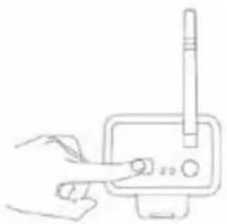
natural_image
Line drawing of a hand holding a pen and a stylus above a device (no text or symbols)Dimensions : 132x64x57 mm (sans support)
Ecran :
natural_image
Line drawings of three different security camera modules with no visible text or symbolsEcran :
natural_image
Line drawing of a device setup with a handheld device, power outlet, and connected devices (no text or symbols)Câble vidéo
Mode d'emploi :
natural_image
Line drawing of a device with a power cord, antenna, and control panel (no text or symbols)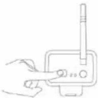
natural_image
Hand holding a pen inserted into a device with a cylindrical component (no text or symbols visible)Beeldscherm:
natural_image
Line drawings of three different security camera modules with no visible text or symbolsBeeldscherm:
natural_image
Line drawing of a device with a small electronic component connected to a screen (no text or symbols)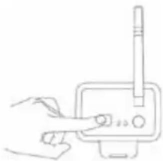
natural_image
Simple line drawing of a hand pointing at a device with a pen inserted (no text or symbols)Monitor:

natural_image
Line drawings of three different security camera modules with wiring and connectors (no text or symbols)Monitor:
natural_image
Line drawing of a device setup with a pen, power outlet, connected to a monitor and antenna (no text or symbols)Cavo Video
Istruzioni utente:
natural_image
Line drawing of a device with a rectangular component connected to a screen and antenna, showing no text or symbols.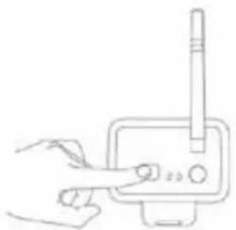
natural_image
Hand holding a pen or stylus interacting with a device (no text or symbols visible)Monitor:

natural_image
Line drawings of three different security camera modules with no visible text or symbolsMonitor:
natural_image
Line drawing of a wireless device setup with a handheld device, power outlet, and connected devices (no text or symbols)Cable de vídeo
natural_image
Line drawing of a device with a small electronic component connected to a screen and antenna (no text or symbols)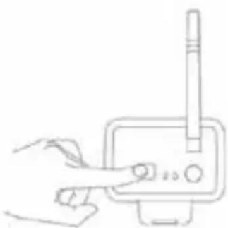
natural_image
Simple line drawing of a hand pressing a button on a device (no text or symbols)Monitor:
natural_image
Line drawings of three different security camera modules with wiring and connectors (no text or symbols)Monitor:
natural_image
Line drawing of a device setup with a handheld device, power outlet, and connected devices (no text or symbols)Cabo de Vídeo
natural_image
Line drawing of a portable electronic device connected to a small electronic device via cable (no text or symbols)Note: for playback functions it's necessary that an SD card is inserted or an external hard disk drive is connected.
natural_image
Line drawing of a hand holding a pen and a stylus above a device (no text or symbols)Monitor:
natural_image
Line drawings of three different security camera modules with no text or symbolsMonitor:
natural_image
Line drawing of a device setup with a handheld device, power outlet, and connected devices (no text or symbols)Videokábel
natural_image
Line drawing of a device with a power cord, antenna, and control panel (no text or symbols)
natural_image
Simple line drawing of a hand pressing a button on a device (no text or symbols)Monitori:
natural_image
Line drawings of three different security camera modules with wiring and connectors (no text or symbols)Monitori:
natural_image
Line drawing of a device setup with a handheld device, power outlet, and connected devices (no text or symbols)Videojohto
Käyttöohjeet:
natural_image
Line drawing of a device with a small electronic component connected to a screen (no text or symbols)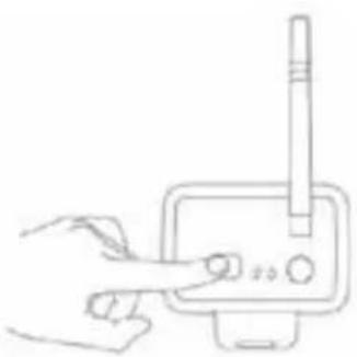
natural_image
Line drawing of a hand interacting with a device (no text or symbols)Monitor:
natural_image
Line drawings of three different security camera modules with no visible text or symbolsMonitor:
natural_image
Line drawing of a device setup with a pen, power outlet, connected to a monitor and antenna (no text or symbols)Videokabel
natural_image
Line drawing of a device with a power cord, antenna, and control panel (no text or symbols)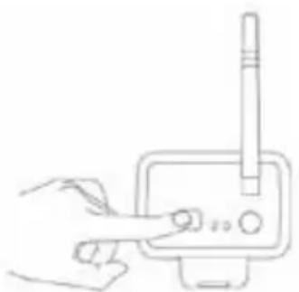
natural_image
Line drawing of a hand interacting with a device (no text or symbols)Monitor:
natural_image
Line drawings of three different security camera modules with no visible text or symbolsMonitor:
natural_image
Line drawing of a device setup with a pen, power outlet, connected to a monitor and antenna (no text or symbols)Video kabel
Pokyny k použití:
natural_image
Line drawing of a device with a rectangular component connected to a screen and antenna, showing an attached circuit board (no text or symbols)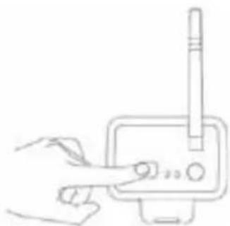
natural_image
Line drawing of a hand holding a device with a pen inserted (no text or symbols)Monitor:
natural_image
Line drawings of three different security camera modules with no visible text or symbolsMonitor:
natural_image
Line drawing of a device setup with a pen, power outlet, connected to a monitor and antenna (no text or symbols)Cablu video
natural_image
Line drawing of a device with a rectangular component connected to a screen and antenna, showing no text or symbols.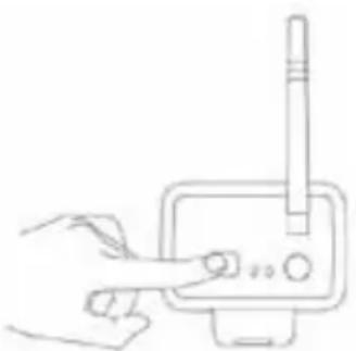
natural_image
Line drawing of a hand interacting with a device (no text or symbols)Οθόνη:
natural_image
Line drawings of three different security camera modules with no visible text or symbolsΟθόνη:
natural_image
Line drawing of a device setup with a handheld device, power outlet, connected to a monitor and antenna (no text or symbols)Καλώδιο βίντεο
Οδηγίες χρήσης:
natural_image
Line drawing of a device with a rectangular block connected to a screen and antenna, showing no text or symbols.
natural_image
Hand holding a pen inserted into a device with a cylindrical component (no text or symbols visible)Skærm:

natural_image
Line drawings of three different security camera modules with no visible text or symbolsSkærm:
natural_image
Line drawing of a device setup with a pen, power outlet, connected to a monitor and a radio (no text or symbols)Video Cable
Brugervejledninger:
natural_image
Line drawing of a device with a small electronic component connected to a screen (no text or symbols)
natural_image
Hand holding a pen inserted into a device with a pen tip inserted (no text or symbols visible)Spenning: 5 V DC/650 mA
natural_image
Line drawings of three different security camera modules with wiring and connectors (no text or symbols)Monitor:
natural_image
Line drawing of a device setup with a pen, power outlet, connected to a monitor and antenna (no text or symbols)Videokabel
Brukerveiledning:
- Sett inn et SD-kort i monitorens spor for SD-kort. Eventuelt kan du koble en ekstern harddisk til monitorens USB-port-
natural_image
Line drawing of a device with a rectangular block, cable, and antenna connected to a screen (no text or symbols)Systemet
natural_image
Line drawing of a hand interacting with a device (no text or symbols)Monitor:
natural_image
Line drawings of three different security camera modules with no visible text or symbolsMonitor:
natural_image
Line drawing of a device setup with a handheld device, power outlet, and connected devices (no text or symbols)Przewód wideo
natural_image
Line drawing of a device with a small electronic component connected to a screen and antenna (no text or symbols)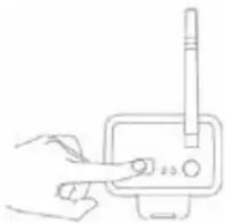
natural_image
Line drawing of a hand interacting with a device (no text or symbols)Монитор:
natural_image
Line drawings of three different security camera modules with wiring and connectors (no text or symbols)Монитор:
natural_image
Line drawing of a device setup with a pen, power outlet, connected to a monitor and antenna (no text or symbols)Видеокабель
natural_image
Line drawing of a device with a small electronic component connected to a screen and antenna (no text or symbols)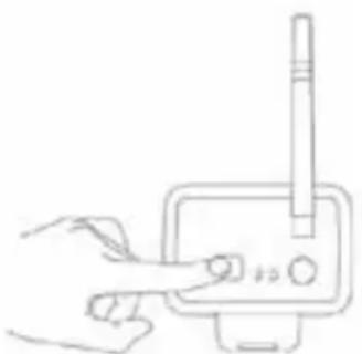
natural_image
Line drawing of a hand inserting a device into a device (no text or symbols)Monitör:
natural_image
Line drawings of three different security camera modules with no visible text or symbolsMonitör:
natural_image
Line drawing of a device setup with a handheld device, power outlet, and connected devices (no text or symbols)Görüntü Kablosu
natural_image
Line drawing of a device with a rectangular component connected to a screen and antenna, showing an attached circuit board (no text or symbols)Sistem
natural_image
Hand holding a pen and a stylus interacting with a device (no text or symbols visible)


- Introduction:
- Technical specifications:
- Camera:
- LCD monitor:
- Safety precautions:
- Product description:
- Monitor:
- Installation instructions:
- User instructions:
- System
- Remarks:
- Record
- Manual Recording:
- PIR Recording:
- Playback
- Delete video
- Camera
- Pairing:
- Active:
- PIP setting:
- Alarm
- Live view:
- Maintenance:
- Warranty:
- Disclaimer:
- Disposal:
- Einführung:
- Gebrauchsanweisung:
- Ecran :
- Mode d'emploi :
- Beeldscherm:
- Istruzioni utente:
- Monitori:
- Käyttöohjeet:
- Pokyny k použití:
- Οθόνη:
- Οδηγίες χρήσης:
- Skærm:
- Brugervejledninger:
- Brukerveiledning:
- Systemet
- Монитор:
- Monitör:
- Sistem
Brand : NEDIS
Model : CSWL120CBK
Category : Surveillance Camera