
P5611OT - Thermostat Emos - Free user manual and instructions
Find the device manual for free P5611OT Emos in PDF.
| Product type | Programmable wireless thermostat |
| Brand | Emos |
| Model | P5611OT |
| Control unit dimensions | 23 × 97 × 122 mm |
| Control unit weight | 143 g |
| Switching unit dimensions | 37 × 115 × 91 mm |
| Switching unit weight | 150 g |
| Control unit power supply | 2 x AA 1.5 V alkaline batteries |
| Switching unit power supply | 230 V AC / 50 Hz |
| Maximum switched load | 230 V AC, 16 A resistive / 5 A inductive |
| Temperature setting range | 7 °C to 30 °C (in 0.2 °C steps) |
| Temperature measurement range | 0 °C to 40 °C |
| Measurement accuracy | ±1 °C at 20 °C |
| Radio range | Up to 100 m in open space |
| Radio frequency | 868 MHz |
| Adjustable hysteresis | 0.1 / 0.2 / 0.5 / 1 °C |
| Preset programs | 6 fixed (P1-P6) + 3 customizable (P7-P9) |
| Operating modes | Comfort, Economy, Anti-freeze, Manual |
| OpenTherm function | Yes |
| Screen backlight | Yes (temporary) |
| Low battery indicator | Yes (icon) |
| Cleaning | Slightly damp soft cloth |
| Repairability | Repair by qualified specialist only |
| Storage temperature | -10 °C to 60 °C |
| Operating temperature | 0 °C to 40 °C |
Frequently Asked Questions - P5611OT Emos
User questions about P5611OT Emos
0 question about this device. Answer the ones you know or ask your own.
Ask a new question about this device
Download the instructions for your Thermostat in PDF format for free! Find your manual P5611OT - Emos and take your electronic device back in hand. On this page are published all the documents necessary for the use of your device. P5611OT by Emos.
USER MANUAL P5611OT Emos
The P56110T thermostat is designed for controlling heating and air-conditioning systems. Unlike conventional home thermostats, the P56110T thermostatic system has a separate, wirelessly connected control unit (transmitter) and a switching unit (receiver). The switching unit is used to connect and switch heating/air-conditioning systems while the portable control unit is used to control and adjust temperature. The units communicate with each other via radio signal. The advantage of the system is its variability and easier access to temperature controls.
Important
- Before first use, make sure to read carefully the Operating Manual for the thermostat, as well as the manual for the boiler or air-conditioning equipment.
- Turn off power before installing the thermostat!
- Installation should be carried out by a qualified professional!
- Abide by prescribed standards during installation.
SPECIFICATIONS
Switched load: max. 230 V AC; 16 A for resistive load; 5 A for inductive load
Clock accuracy: ±60 seconds/month
Temperature measurement: 0^ to 40^ with 0.1^ resolution; accuracy ± 1^ at 20^
Temperature setting: 7^ to 30^ in 0.2^ increments
Differential setting: 0.1; 0.2; 0.5; 1^
Operating temperature: 0^ to 40^
Storage temperature: -10 °C to 60 °C
Unit interconnection: via 868 MHz radio signal, max. 25mW e.r.p.
Pairing capacity: max. 6 receivers
Transmitter unit range: up to 100m in an open space
Power supply:
Control unit (transmitter) 2 × 1.5 V type AA (LR6) batteries
Switching unit (receiver) 230 V AC/50 Hz
Dimensions and weight:
Control unit: 23 × 97 × 122 ~mm ; 143 g
Switching unit: 37 × 115 × 91 ~mm ; 150 g
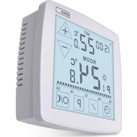
Control (Portable) Unit
(see Fig. 1)
1-day of the week
12 - set temperature
2-clock
13 - frost indication
3 - comfort mode
14 - operation status icon
4 - economy mode
15 - battery status indication
5 - manual control
16 - current room temperature
6 - programme preset
17 - day profile
7 - comfort/economy mode switch
18-DOWN button
8-UP button
19 - change temperature
9 - change clock
20 - illuminate screen
10 - change programme
21-RESET
11-wireless communication icon
Removing the Rear Cover of the Control Unit
(see Fig. 2)
- Use a screwdriver to press and hold the inner lock.
- Remove THE front cover.
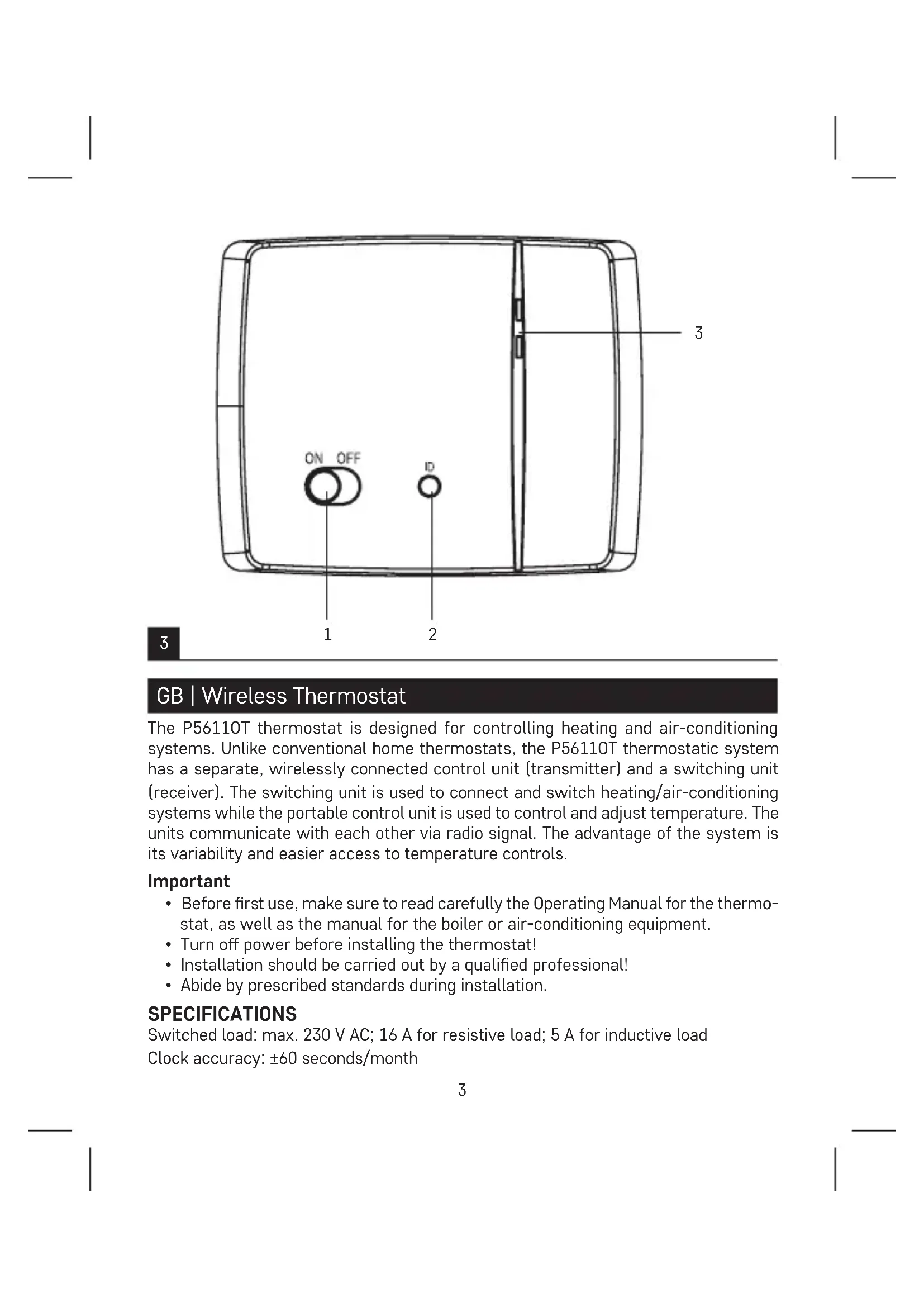
Switching Unit
(see Fig. 3)
1 - main switch
2 - pairing button
3-LED indicators
LED Indicators
- Blue LED indicates the switching unit is powered by 230 V AC. If the unit is not connected to power or if the main switch is in the OFF position, the blue LED is not lit.
- Red LED is lit while the heating/air-conditioning system is active.
Main Switch
If the heating/air-conditioning system is not used for an extended period of time, it is recommended to turn the switching unit off (move the main switch to the OFF position).
INSTALLATION
Pairing the Control Unit with the Switching Unit
Pairing enables transmission of information between the control unit and the switching unit.
The units pair automatically (self-learning) after pressing the "ID" button.
Attention: When pairing two or more receivers, it is necessary to have pairing mode activated on all receivers simultaneously!
- Insert 2 × 1.5 V AA batteries into the control unit (make sure polarity of the batteries is correct). Use alkaline batteries only, not rechargeable ones.
- Connect the switching unit correctly to the power source, and press and hold the "ID" button; the top red LED starts flashing.
Long-press the screen illumination button ( ) on the control unit within 10 seconds.
Both units will automatically pair and the icon will be displayed. The red LED on the switching unit will stop flashing and goes out.
If the pairing of the units fails, the icon will be flashing instead.
Testing Wireless Communication between the Units
- Use the button to select a temperature a few degrees higher than the current room temperature.
- Wait for approximately 10 seconds or press the button.
- The red LED on the switching unit will light up.
- If the LED does not light up, move the control unit closer to the switching unit. Press the button to set a value which is lower than the room temperature – the receiver must switch off.
- Repeat steps 1 to 4.
The maximum range between the control and switching unit is 100m in an open space. The range may decrease indoors as the signal has to pass through walls and other obstacles.
- Press the "RESET" button once the test is complete.
Deleting the Memory (Code) of Paired Units
To delete the pairing code used between the control and switching unit, follow the instructions below. Press and hold the "ID" button on the switching unit; the red LED will start flashing. Short press the "ID" button again within 10 seconds. The red LED will stop flashing and goes out. The pairing code is deleted.
Replacing the Original Thermostat
ATTENTION: Before replacing the thermostat, disconnect the heating/air-conditioning system from the power in your flat. This will prevent potential injury by electric current. Before disconnecting the leads, read the following instructions carefully.
- Turn off the original thermostat and remove the thermostat cover.
- Unscrew the thermostat from the wall panel.
- Unscrew the connecting rear panel of the thermostat from the wall. Pull the rear panel out a sort distance from the wall, but do not disconnect any wires yet.
Marking Wires
- Identify and disconnect each wire.
- Secure the wires against getting torn out.
- If the hole behind the thermostat is too large, seal it with insulating foam to prevent air flow. This is to prevent incorrect temperature measurement.
Thermostat Placement
Thermostat (control unit) location significantly affects its function. Place it in a room where members of the family spend most of their time. Choose a spot preferably on an inside wall where air circulates freely and there is no direct sunlight. Do not place the thermostat in the vicinity of heat sources (such as TV sets, radiators, fridges), or close to a door (due to frequent shocks or vibrations). Failure to comply with these recommendations will prevent proper control over room temperature.
Mounting the Switching Unit onto the Wall
- Remove the rear cover of the switching unit.
- Mark positions for holes.
- Drill two holes, carefully insert the plastic wall plugs into them and use two screws to mount the rear cover of the switching unit.
- Connect the wires to the labelled terminals according to the wiring diagram.
- Complete the installation by fitting the switching unit onto the mounted rear cover.
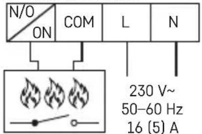
Wiring Diagram
The P56110T thermostat can be used with any one-stage heating or air-conditioning system.
NO-switched contact
COM - contact for the switch
L-230 V AC power connection
N-neutral conductor
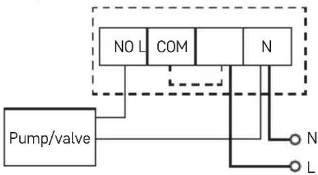
Pump/Motorised Valve Wiring Diagram
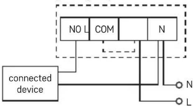
Floor Heating Wiring Diagram
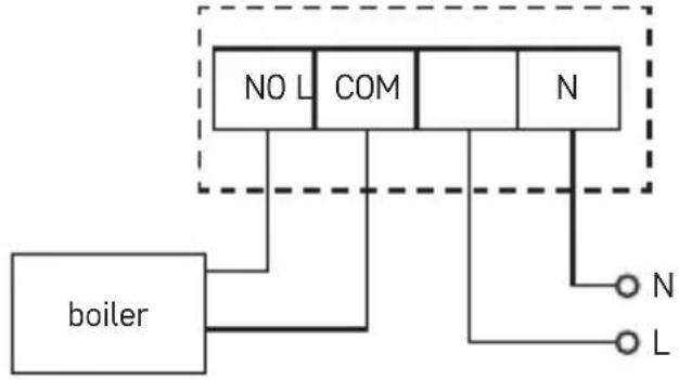
Boiler Wiring Diagram (Zero Voltage Switching)
- The pre-installed wire coupler between COM and L will not be connected.
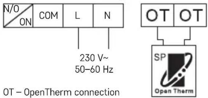
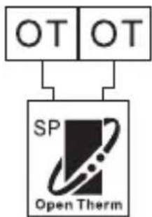
OpenTherm Connection Diagram
Mounting the Control Unit (If You Do Not Wish to Use the Unit's Portability)
- Remove the control unit's rear cover.
- Mark positions of the holes for rear cover.
- Drill two holes, carefully insert plastic wall plugs and push them in flush with the wall.
- Use two screws to mount the rear cover of the control unit.
- Complete the installation by fitting the switching unit onto the mounted rear cover.
Selecting Heating/Air-Conditioning System
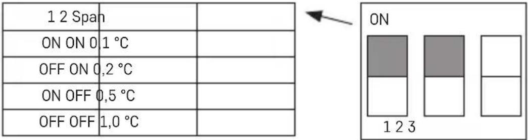
- Remove the rear cover of the control unit - the printed circuit board inside has 3 DIP switches. These 3 switches are used to adjust the temperature differential and switch between the heating/air-conditioning system.
- Adjust the DIP switch (position 3) depending on your choice of heating or air-conditioning system as indicated in the following figure.
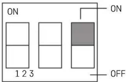
ON-heating OFF-air-conditioning
Selecting Temperature Differential
The temperature differential (hysteresis) is the difference in temperature required for switching the system on and off. If, for example, you set the temperature in the heating system to 20^ and differential to 0.2^ , the thermostat activates heating as soon as room temperature drops to 19.8^ and switches heating off when temperature reaches 20.2^ . Set the DIP switches (positions 1 and 2) depending on your choice of temperature differential as indicated in the following figure.
Installing Batteries
The P56110T thermostat is powered by two 1.5 V AA batteries.
- Insert two AA batteries into the battery compartment located inside the control unit. Make sure to observe correct polarity. Use 1.5 V alkaline batteries only; do not use rechargeable 1.2 V batteries (due to their lower voltage). When you first start the unit, the screen must show the time and room temperature.
- If the screen shows different data, gently press the "RESET" button. To do this, use a thin, straight object, such as an unfolded paper clip.
- Replace the rear cover once the batteries are in place.
- Before you turn on the main switch of the switching unit, press the "RESET" button once. The thermostat is now ready for use.
Attention: After inserting batteries, the transmitter needs up to about 30 minutes to stabilise parameters!
Setting the Time/Date
- Press the button to set the day and time. The day indicator (number 1 – Monday to 7 – Sunday) will start flashing.
- Use the button to select the corresponding day number.
- Press the button and use the or button to set hours. Hold the or button to speed up the adjustment.
- Press the button and use the or button to set minutes. Hold the or button to speed up the adjustment.
- Confirm the setting using the button. If no button is pressed for 10 seconds, setting mode ends automatically.
Screen Illumination
Pressing the button activates screen illumination. If no button is pressed for 10 seconds, illumination will turn off.
Setting Temperature
- Press the CHANGE TEMPERATURE button to switch to temperature setting mode.
- Repeatedly press the button to switch between economy mode (icon) and comfort mode (icon).
- Use the button to set both temperatures in 0.2^ increments.
- Save the setting by pressing the CHANGE TEMPERATURE button again. If no button is pressed for 10 seconds, setting mode ends automatically. The default comfort temperature is 21^ for the heating system and 23^ for air-conditioning; the default economy temperature is 18^ for the heating system and 26^ for air-conditioning. Values can be changed, as necessary.
SETTING A PROGRAMME
Selecting Week/Day
- Press the "P" button; the day indicator will indicate which day is being programmed.
- Repeatedly press the button to select the day you wish to programme. You can choose to programme: the whole week (1, 2, 3, 4, 5, 6, 7), workdays (1, 2, 3, 4, 5), weekend (6, 7) or each day individually.
Selecting a Pre-Set Programme
- Press the "P" button again to set a programme.
| Programme Number Programme Profile | |
| Programme 1: Comfort temperature all day | 00 06 12 18 24 |
| Programme 2: Economy temperature all day | 00 06 12 18 24 |
| Programme 3: Combination of comfort temperature and economy temperature | 00 06 12 18 24 |
| Programme 4: Combination of comfort temperature and economy temperature | 00 06 12 18 24 |
| Programme 5: Combination of comfort temperature and economy temperature | 00 06 12 18 24 |
| Programme 6: Combination of comfort temperature and economy temperature | 00 06 12 18 24 |
| Programme 7: Custom | 00 06 12 18 24 |
| Programme 8: Custom | 00 06 12 18 24 |
| Programme 9: Custom | 00 06 12 18 24 |
Dark bars indicate comfort mode settings, otherwise the thermostat is set to economy mode 00 06
-
Use the or button to select one of the programmes, P1-P6. These programmes are pre-set (cannot be modified) and their profiles are shown in the figure above.
-
Press the "P" button again to confirm the selected programme for the given day/ week and exit the setting mode.
Setting a Custom Programme
- If you select a custom programme (P7-P9) during programme selection, you can press the "P" button to adjust the programme's temperature settings.
- Press the button to choose an hour, which is indicated with the flashing of the icon. Press to choose whether you want the system to be set to comfort or economy mode at that time.
- After you have set the profile for the entire day, press the "P" button to acknowledge the selected programme and exit the setting mode.
Temporary Change of a Set Programme
In standard mode, where temperature is controlled by a selected programme, pressing the button switches from the currently set programme to comfort or economy mode. When the selected programme is switched over in this way, the icon is displayed together with the selected control mode icon.
This setting will cancel automatically upon the next temperature change in the programme.
Temporary Change of Temperature Setting
In standard mode, where temperature is controlled by a selected programme, you can press the button to override the current temperature setting. When the temperature is changed, the newly set temperature will be displayed together with the icon, with the and icons disabled. Press any button (except or to exit the temperature setting mode. If no button is pressed for 10 seconds, setting mode ends automatically. This setting will cancel automatically upon the next temperature change in the programme.
Note: If you wish to use the manually changed temperature for an extended period of time, we recommend doing so in programme no. 1 or 2.
Calibrating Room Temperature
Long-press the "P" button. "CAL" will appear on the screen and the set temperature value will be flashing.
Repeatedly press the or button to adjust the temperature (-3.0 °C to 3.0 °C, in 0.5 °C increments).
Press the "P" button to confirm the setting.
Calibration of room temperature is used, for example, if the thermostat shows 21^ but you want it to show 20^ . In that case, the calibration value should be set to -1^ .
Anti-Freeze Mode
- Press the and buttons simultaneously to activate the anti-freeze mode (for heating mode only). and will appear on the screen and will not be displayed.
- Press any button (except ) to end anti-freeze mode.
- Default temperature for anti-freeze mode is 7^
Setting OpenTherm Parameters
Applies only to heating mode.
-
Long-press the button to access OpenTherm settings. "01" will appear in the left corner and water temperature in the OpenTherm boiler will appear in the centre (if the thermostat is not receiving a temperature reading, "... will be displayed instead).
-
Press the button. "02" will appear in the left corner and temperature of the water returning back to the boiler will appear in the centre (if the thermostat is not receiving a temperature reading, "---" will be displayed instead).
-
Press the button. "03" will appear in the left corner and the temperature of hot water will appear in the centre (if the thermostat is not receiving a temperature reading, "... will be displayed instead).
-
Pressing the button opens settings for temperature limit switching values. "04" will appear in the left corner and OFF will start flashing in the centre of the screen. To switch between ON/OFF, use the or button.
-
If you selected ON in the previous step, pressing / opens settings for the maximum temperature limit switching value. "05" will appear in the left corner and temperature will appear in the centre. You can adjust the temperature using the and button (30 to 80^ in 1^ increments).
-
Pressing / opens settings for hot water switching. "06" will appear in the left corner and OFF will start flashing in the centre of the screen. To switch between ON/OFF, use the button.
-
If you selected ON in the previous step, pressing / opens settings for hot water temperature. "07" will appear in the left corner and temperature will appear in the centre. You can adjust the temperature using the ▲ and button (25 to 65^ in 1^ increments).
-
Pressing opens the control switching settings. "08" will appear in the left corner and ON will start flashing in the centre of the screen. To switch between ON/OFF, use the or button.
-
Press the "P" button to confirm the setting.
OpenTherm Error Indication
If an error occurs in the OpenTherm boiler, an "Exxx" error code will appear on the screen, where "xxx" is between 0 and 255.
Changing Batteries
When the battery icon appears on the screen, replace the batteries:
- Switch off power to the receiver unit.
- Remove the control unit's rear cover.
- Replace the batteries with new 1.5 V alkaline AA batteries.
- Replace the rear cover.
- Press the "RESET" button once and then restore power to the receiver unit.
Upkeep and Maintenance
The product is designed to serve reliably for many years if used properly. Here are some tips for proper operation:
- Read the manual carefully before using this product.
- Do not expose the product to direct sunlight, extreme cold and humidity, and sudden changes in temperature. This would reduce measuring accuracy.
- Do not place the product in locations prone to vibration and shocks – may cause damage.
- Do not subject the product to excessive force, impacts, dust, high temperatures or humidity - doing so may cause malfunction, shorten battery life, damage the batteries or deform the plastic parts.
- Do not expose the product to rain or high humidity, dropping or splashing water.
- Do not place any open flame sources on the product, e.g. a lit candle, etc.
- Do not place the product in places with inadequate air flow.
- Do not insert any objects in the product's vents.
- Do not tamper with the internal electric circuits of the product - doing so may damage the product and will automatically void the warranty.
- The product should only be repaired by a qualified professional.
- To clean the product, use a slightly moistened soft cloth. Do not use solvents or cleaning agents - they could erode the plastic parts and cause corrosion of the electric circuits.
- Do not immerse the product in water or other liquids.
- In the event of damage or defect on the product, do not perform any repairs by yourself. Have it repaired in the shop where you bought it.
- This device is not intended for use by persons (including children) whose physical, sensory or mental disability or lack of experience and expertise prevents safe use, unless they are supervised or instructed in the use of the appliance by a person responsible for their safety. Children must always be supervised to ensure they do not play with the device.

Do not dispose with domestic waste. Use special collection points for sorted waste. Contact local authorities for information about collection points. If the electronic devices would be disposed on landfill, dangerous substances may
reach groundwater and subsequently food chain, where it could affect human health.
Hereby, EMOS spel. s r. o. declares that the radio equipment type P56110T is in compliance with Directive 2014/53/EU. The full text of the EU declaration of conformity is available at the following internet address: http://www.emos.eu/download.
CZ | Bezdrátovy termostat
LED indicatory (diody)
SK | Bezdrótov'termostat
Wskazniki LED (diody)
BcTaHOBJIeHHbaxKaHOI TempepaTpyn
- Hatachitb ha khoNky HAIALITyBAHHY TEMNEPATPUN. Ipy nepexody B peKIM HalaSTyBaHHY TempepatpN.
- Hatachitb noBtOpHo KhoNky /C nI nepeMkaHHa mix ekOHOMiHmHaHa- 1uTyBaHHaMn TemepaTpyn (ikoHka ) Ta kOΦopTHoi TemepaTpyn (ikoHka
- KhoNkoIO a6o HalaTuYte o6nDbI TeMpepaTyprn B Kpokax no 0,2°C.
- Khonkoi HAJALUTYBAHHY TEMNEPATPYN 36epertn hanaHTyBaHHN.
Ku npotrrom 10 cekyH, He HATnCKaTN JKOHOI KHOKN, peXIM HAnaHTyBaHHra 3aKiHyETbCABTOMaTHUHO.
PonepeHbO BCTaHOBHeHa TemnepaTpy KOMΦopTy cTaHOBtB 21 °C dIy CnCTeMn OaJIeHH Ta 23 °C dIy KOHnIioHEpa, ekOHOMHa TcMnepaTpy 18 °C dIy CnCTeMn OIaJIeHH Ta 26 °C dIy KOHnIioHEpa. Napametpn MoJHa BCTaHOBtN 3rIHD HoobxHocTi.
HAJALUTYBAHHI NPOI PAMN
Bn6ip TnXHr /nH
- Hatncitb knaibiy ^P , iHnkaTOp nHa BINO6paXaE 3anporpamOBaHn DeHb.
- Hatackai Te KhoKy a6o Jbka pa3iB, 06 Bn6paTn DeHb, knn noTpi6Ho 3anporpaMyBaTu. IpnorpaMByaHHa MoXHa Bn6paTu: cJInn TnXdHb (1, 2, 3, 4, 5, 6, 7), po6ouh TnXdHb (1, 2, 3, 4, 5), Bnxdi (6, 7) a6o OkpemDiHi.
Bn6ip 3anporpamOboHoI nporpamN
- 3HOBy HATnCHiB Ha KhoNky, P" uOb HanaaTByBaTn nporpaMy.
Tmucoba 3MiHa HanaTuBaHHa TempeaTpHi
Y 3BnauHomy peximi peyIIOBaHHa TeMnepaTyPi o6paHO nporpaMOHaTncHyBHN Ha KhoNky a6o MoXHa 3aMHInn akTyAlbHe HanaWtBuHHa TeMnepaTyPi. KoJIi TempePaTypa 3MiHOeTbcra, BiO6paKaAcTbcra HOBa BCTaHOBHeHa TempePaTypa 3 iKOHKO
Ta 3 BUMKHeHIMn iKOHkAmu . HATNCIb 6yDb-ky KHOKNy (Kpim KHOKN a6o , uO6 BnITn 3 peXmMy HanaSTyBaHHa Tempeatypn. kKIO npotarom 10 cekyn He HATNCKaTN JODHOI KHOKN, peXm HanaSTyBaHHa 3akHcyETbcra ABToMaTHUHO. Lc e HanaSTyBaHHa 6yde aBTOMaTHUHO nepepbaho IHWOIO 3MiHOIO Tempeatypn B nporpaMI. Pnmitka:
Якwo BxoxeTe BnKOpncTObyBaTu pyuHy 3MiHy Tempeatpyn npOTaROM TpUbaNOrO yacy, MN peKOMeHnyEmo ii pobntu B nporpaMax No1 abo 2.
Kaji6pyBaHHaKimHaTHOI TemnepaTpy
HaTnchItb i npitpmaTe KhoNky ,P" , Ha dncnnei 3'ABNTbcra , CAL", BCTaHOBneHe 3Na-ueHHa6yde MmraTu.
KaHnHa nCnnei 3'ABnEtbcI KOHka 6aTapeKn, 3amHtB 6aTapeKn:
-
Bumkhitb Jxepepo KINBJIeHHn npinMaIbHoro 6loky.
-
3HIMITb 3aHIO KPNKy 6nOKy ynpabJIHHra.
-
3aMHITb dHi 6aTapeKn HOBmN 1,5 B LyxHmN 6aTapeKam Tnny AA.
-
3HOBy BCTaHOBiTb 3aHIO KpNtKy.
-
Hatnchitb KhoNky, RESET" oDNH pa3, a Notim BiHOBiTB XHBneHHa Do npnMaJIb-Horo 6IOKy.
Dorna Ta o6cnyroByaHH
Bnpi6 ckohctpynoBaHn TaK, 06 npn HaneJHOMy NOBOXeHHi 3 Hm, HaiHNO npaIOBaB 6araTo pokiv. Tyr 3haxoNTbcra DeKInbka pad nI npabNbHOrO oCnyroByBaHHa:
-
Pered BnKOpNCtAHm 6bOro npCtpoU, yBaXHO npOHTaTe NOro IHCTpyKuIO.
Bupi6 He nidaabaTe npaMOMy coHauHOMy npomHHIO, Hd3buaHOMy xoNoy, BONORCTI Ta p3kIM 3mHAM TEMnepaTpyu. Ue moNIO 6 3HN3NTU TOHICTb 3HImaHHJ.
Bupi6 He nomiuatay y micx de 6yBaic Biipauia qn TpncHHa -e moKe npuHHTN nooKoJXeHH.
Bnpi6 He nipdaBaTe Hnd3BuaHOMy Tncky, ynapam, npoxy, Bucoki TemnepaTpyi a6o BoIorocti- ce MoIIO 6 noSKoJKNTH cYHKciIO BnpOby, ckopOTNT eHepreTuHy kictb, noSKoJNTb BaTapeKn Ta deOpMyBaTN pIacTKOBi qactHH.
Bpi6 He niDaaBte Douy Ta BOIOROCTi, KpannMaT Ta 6pn3KaM BOn.
He nomiatae Ha Bnpi6 JxOHe DxepeNo BiKpnToro BorHIO, HAnp. 3aanaJeHy cbiuKy Ta iHue.
He nomiatae Bnip6 B Micx, De He doCTaTHbO 3abe3neueHa cnpkylaqia Nobitpr.
He BCobyTe y npocTip BEHTnIaIi BnOb6y JODHnx PpeMeTIB.
He BTPyaIeTecy BHyTpIiHHi eJIeKtpuHn IaHIOB Bnp6y-MoKeTe NOro NoKOJNTu UHM ABTomATNuHO 3aIKHHTN DiCHN rapaHTIH NCTPOK.
Bpi6 IOBHeH peMOHTyBaTH TiIbKn KBaJIcIKOBaHm caxiBeU.
-Дячшенив ВИКОПСТОВЕВОЛУ, M'Ягку raHчIPky. He BИКОПСТОВЕТе рOЗЧИНКИ, Hi МИнHi 3aCobN - BOHМоЖуTB NOшКрЯбати пlaCTмСОВi чаctIHn Ta nOpyшпTи eJeKTPuHHi KOHTyPn.
Bupi6 He 3aHypioTe y Body Ta iHsy piDHy. -
Пошкожени чи.Deфektний Вириб са mis He peMoHTyTe.Здай Te Ioro ДяпpeMoHTy y MaRa3nH De BV NIO rnpd6aann.
- Κeɪ npɪcɪpɪŋ He npɪn3haueHŋ dʒə KOpɪcTbYBaHŋ Oco6aɪ (BkIIOUHO dɪteɪ), dʒə KOTpɪx φɪ3nɪHa, nòuTTeBA uŋ pɔ3yMoBa He3dɪ6hɪcɪt b, uŋ He IDOCTaTOK IocBɪdy Ta 3HaHb 3a6bOρoHæne Hm 6e3neuHo KOpɪcTbYBaTncr, Tɔdi kʌŋo Taka oco6a He 6bYe iɪd IORJIaDOM, uŋ JAKUθ He 6bʌna InpoBeDEHa dʒə Heɪ IHCtpyKTaŋ KOpɪcTbYBaHŋ BIDNobɪdHŋO Oco6oɪ, KOTpa BɪdNobɪdae 3a II 6e3neuHicltb. He0xbXɪdNo DɪbUTnC r 3a DiTbMn, Ta 3a6e3neuHTn TaK, 506 BOH 3 npɪcTpOeM He rpaɪnCra.

He BnkyuTe eNektpuHi npncTrooi k HecopToBahi KOMyHaIbHi BiXoH, KopnCTyInTecb MiczM 360py KOMyHaJIbHnx BiXoDIB. 3a akTyaNbHOIO IHOpMaucieio npo Micz 360py 3BepTaItecB do yctAHOB 3a Miccem npoxBaHHra. RaioeK
TpnuHIpncToPoPi03MiueHi Ha Micx 3 BiXoJaMn, To He6e3neuHi peOBNH MoKyTb npOnHKaTN Do NiI3emHnx Boi i icTaTncb Do XapOBOro oBiy Ta noIKoJkyBaTu BaWe 3dOpOB'
LIMiipnemcTBO EMOS spol. s r.o. nporonoWye, 0o Tn paoooaadhaHH P5611OT BiNobidae DnpekTbAm 2014/53/EU. NobHn TeKCT EC nporonoWeHH npo BIDNOBIDHcTB MoKaHaTn Ha cboMy caTi http://www.emos.eu/download.
RO|MD | Termostat fãrã fir
TEXHNUECKXAPAKTEPNUCTNKN
Ппевклioчван TOВар: Мкс. 230 V AC; 16 A пи akТиBEн TOВар; 5 A пи ИДуКТиBEн TOВар
MaKcImaJIeH 6poi CbIp3aHIyCTpoIcTBA: MaKc. 6 npIeMHnka
06xbaT Ha Bpb3kata: 100 m Ha oTKpntO
3axpaHbHe:
Бл_OK 3a управлице (празавател) 2 × 1,5 V тин AA (LR6) 6атери
PpeBkIIOUBaU,MoUJ (npneMnK) 230 V AC/50 Hz
Pa3mepn TeTJIO:
Блok 3a упавелен: 23 MM × 97 MM × 122 MM; 143 r
PpeBkIIOuBaU,MOyU:37MM×115MM×91MM;150
UnpablaBa( npenocm) moyn
(BX.ΦnF.1)
1-ENOTCEMNzata
11-нкогазбe3хичнаКOMунkaцяЯ
2-achOBHnK
12-3aDaaBHe Ha TeMnepaTypa
3-KOMΦopTeHpeKIM
I36paHHeHaTeMnepaTypeHdpepeHuaI
Temnepaupnrtinnepehun (xnctepe3nc) npedctabnaBpa3nkaTb TEMnpaypata, Heobxodma 3a BkIIOUbaHe n3KIOUbaHe Ha cncTeMaTa. Hanpimep, ako B peKmHa OTONJIeHne 3aIaeHata TemnepaTypa e 20^ , aINcpehenuJbTe 0,2°C, TepmoCTaTbT ce BKIOUBA, KOrato ctaHata TemnepaTypa cnaHne do 19,8°C, n ce n3KIOUba, KOrato TEMnpaTypa IocTHnre 20,2°C. YcTaHOBe Te npoRpaMpaUN KIOUeta 1 n 2 B 3aBNCIMoCT OT BaSInr N3bOp Ha TemnpaTypen DIncpehenuaJI, KaKTo e yKa3aHO Ha cNeIHATA cnrypa.
HcTaJnpaHe Ha 6aTeepn
TepmoctaTbT P56110T ce 3axpaHbA ot Dbe 6aTepn 1,5 V AA.
- Пocтавete Дve 6atepnn TnA A B npedHa3HaueHTo 3a Tx BbTpE B 6loka 3a ynpabBHeHne. 3aBnKInTeJHo Cna3BaIte NocOeyHata NopApHocT. 3noN3BaIte cMo aKanHn 6atepnn 1,5 V; He n3noN3BaIte npesapexdaun ce 1,2 V 6atepnn (napnNo-HnCKOTo Hm HappeXeHne). Ppr nbpBOHaayHnO CTapTnpaHne Ha ModyJa, ekpaHbT Tp8Ba Da nokaxe YacbT n TempepaTypata B NOMueHneTO.
- Ako ekpaht noka3Ba pa3nucn daHHn, haTnche Te neko 6ytoHa RESET. 3a ceIta H3no3BaTe TbHbK npab npedMeT, KaTo Hanp. pa3bHaT KnaMep.
- NocTaBETe 06paTHo 3aHnI KaNk CJIeK KaTO bATEpuNTe Ca Ha MrcTOTO cN.
- Ппени Клочente Галовни певкювATEн на певкючваши мolyн, натугшешену reset. Терmoста тсera e rotob 3a paBOTa.
BnmaHne:Cnei noctabHe Ha 6aTePnte npedabatEnT ce hyxdae ot okono 30 mHyTu, 3a da cTabnna npapothte cn napametpn!
Hactpoika ha yaca/daTata
- Hatachete bytoh, 3a da hactponte daTata uaca. NndkaTopbT 3a deHn (Homep 1- noheJIHHK do 7 - HeJe) ue 3anoue He da mHa.
- Ⅰ3noJ3BaIe TmHbToH 3a H36npaHe Ha CbOTBETHnH OMeP 3a DeH.
- Hatnche6ytoH n H3noJ3BaIteA nn 6yToH 3a HacTpoBae He Ha yacobete. 3aipbXTe Ann 6yToH 3a yckopraHe Ha perylnpaHeto.
- HatncheTe 6yToH n H3noJ3BaIteA nn 6yToH 3a HacTpoBHe Ha MNHyTnTe. 3aipbXkTe Ann 6yToH 3a yckOpBaHe Ha peryInpaHeTo.
- NotBbpeTe Hactpoikata c 6yToH
Ako He ce HATNCHE 6byToH 3a 10 cekyHn, peKIMbT Ha HAcTpoiKa CbPbJbA bTOMaTNUHO.
OcbetJIeHHe Ha eKpaHa
HaTnCKaHTo Ha cyToH aKTHBnpa ocBeTneHneTo Ha ekpaHa. Ako He ce haTncHe 6yToH 3a 10 cekyn, ocBeTneHneTo ue yrache.
HactpoBaeHaTempepatpata
- Hatachete 6yToHa CHANGE TEMPERATURE 3a npEeKJIIOUbaHe Ha peXIM 3a NaCTPOnKa Ha TempepaTypaTa.
- Повторно натусят e/6утона 3a певкючане мжду ржим ekohьми (Икона) и ржим комсфорг (Инkonha).
3.ИЗнолзBAиTe 甲HуTOH 3a HacTpOиKa Ha Ibete TeMnepaTpyn Cbc CTbNKn OTo 0,2°C. - 3anaMeTe He NaCTpoIkaTa C HATnCKaHe Ha 6yToHa CHANGE TEMPERATURE OTHOBO.
Ako He ce HATNCHE 6yToH 3a 10 ckyHn, peKIMbT Ha HAcTpoKa CBbpWbA ABTOMaTHUHO.
No nopa3bnpaHe cToHocCTTa Ha KOMΦopTHaTe TempeAtypa e 21 ^ C 3a OTonPiTeHa
cNCTema n 23 ^ C 3a oxJaDaUa cNCTema; no nopa3bnpaHe cToHocCTTa Ha IKOHOMuHa
HaTa TempeAtypa e 18 ^ C 3a OTonPiTeHa cNCTema n 26 ^ C 3a oxJaDaUa cNCTema.
CToHocTnte Moat Da ce npomeHr cnopeD hJxHOTO.
HACTPOIBAHE HA IPOPGAMA
N36npaHe Ha ceMnua/JeH
- HatncheTe 6yToH ,P"; nHnKATOpbT Ha deHЯ ue ykaJe KoJ deH e nporpaMnpaH. 2. NOBTOHO HATNCHETe Aunu TyToHa 3a n3bnpaHe Ha deHЯ, KOHTO JxelaTe da nporpamipate. MoXte Da n3bepete da nporpaMnpate: cIJIata ceDMua (1, 2, 3, 4, 5, 6, 7), pa60THnte dHn (1, 2, 3, 4, 5), noUHNITE dHn (6, 7) nII IN BCEKn DeH INHNBnuDyaHNo.
I36npaHHe Na npeBapNTeHNo 3aJaHa nporpama
- HatncheTe ,P" ByToHa OTHOBo 3a 3aDaBaHe Ha nporpaMaTa.
| Номер на п罗рама П reproфны на п罗рама | |
| П罗рама 1: Комфортаlemпера typа праз зцалото дениошие | 00 06 12 18 24 |
| П罗рама 2: Икономинаlemпера typа праз зцалото дениошие | 00 06 12 18 24 |
| П罗рама 3: КомбиашияOT комфорта и Икономина temпера typа | 00 06 12 18 24 |
| П罗рама 4: КомбиашияOT комфорtega и Икономина temпера typa | 00 06 12 18 24 |
| П罗рама 5: КомбиашияOT комфорtega и Икономина temпера typa | 00 06 12 18 24 |
| П罗рама 6: КомбиашияOT комфорtega и Икономина temпера typa | 00 06 12 18 24 |
| П罗рама 7: Кьстмнираha | 00 06 12 18 24 |
| П罗рама 8: Кьстмнираha | 00 06 12 18 24 |
| П罗рама 9: Кьстмнираha | 00 06 12 18 24 |
TbMHnTeJeHTN
00 yka3BaT
HactpoynTe 3a
KOMΦopTeH pexm,
B npOTnBeH cnuyan
TePMoCTaTbT
e HactpoEH Ha
IKOHOMnueH peXMM
00 06.
- Изполваite 6ToH 3a ИЗбиране Ha eДна OT nporpaMITE, P1-P6. Te3n nporpaM Na npedВapnteJIHO 3aJaDEHn (He MoRat Da ce npomeHrT) n npocpHnTe m Ca nOKa3aHn HaФИgypataNo-rope.
- HatncheTe OTHOBo 6ytoH P, 3a Da NotBbPnTe n36paHaTApnpama 3a CbOTBeTHN daH/ceMnua n Da n3Je3eTe OT pexima 3a HactpoiKa Ha nporpama.
HactpoBbHe Ha KbCTbMn3npaHa nporpaMa
- Ako n36epete KbcTbMn3npaHa npoPpMa (P7-P9) no BpeMe Ha n36opa Ha npoPpMa, MoKeTe Da HATNCHeTe ,P" 6yToHa, 3a da peryInpaTe HAcTpOiknte Ha TemnepaTypaTa Ha npoPpMaTa.
- C6byToHnI36peTe Yac, KOItO e yka3aH C MmraHe Ha NkIata. HAtncHeTe 3a n36bpaHe Ha ToBa daJIIN NCKaTe CnCTeMaTa Da ce Hactpon Ha KOMΦopTeH INII INKOHOmUyeH peKIM.
- CnEi KaTo HacTpOnTe npoФmHa 3a ueHЯ DeH, HaTncHete OTHOB6yToH , 3a da notBbPdnte n36paHaTa nporpMa n Da n3ne3eTe ot peKIma 3a NaCTpoIka.
BpeMeHnHa npomHa Ha HacTpoEHa nporpama
B cTaNdapTeH pexm, KbJeTo TempeaTypaTa ce KOHTpOInpa ot n36paHa nporpaMa, HATnCKaHeTo Ha C 6byToHa npeBKnIOUba OT TekyIo HAcTpoEHaTa nporpaMa KbM KOMΦopTeH nI INKOHOMuYeH pexm. Korato n36paHaTa nporpaMa ce npeBKnIOU no To3n Haun, IKoHaTa ice noka3Ba 3aeIDHO C n36paHaTa IKoHa 3a KOHTpOeH pexm. Ta3n HAcTpoiKa ige ce OTMeHN ABTomAtuHo npn CneDbaUaTa TempeaTypHa npomHa B nporpaMaTa.
BpeMeHnHa npomHa Ha TemnepaTyPha HacTpOka
B cTahapTeH pexm, KOrato Tempeatypata ce KOHTpOlnpa ot n36paHa nporpaMa, Moxete Da HATnCHete 6byoH Ani, 3a Da npomHeite TeKyuata TempeatypHa Hactpoika. Korato Tempeatypata ce npomeH, HOBO3aJaEHaTa Tempeatypa Ce n3BeJda Ha DnCnIe 3aeHNo C NkOHATA, C De3aKTbUbpAHn KOnH. HATnCHete BCEKn 6byoH (c N3KIOueHne Ha An) Ta nXoD ot pexmHa HAcTpOka Ha Tempeatypata. Ako He ce HATncHe 6byoH 3a 10 cekyHn, pexmblt Ha HacTpOka CBbpWbA ABTomAtuHo. Ta3n HAcTpOka Ie ce OTMeHn ABTomAtuHo npn CJIeBaUaTa TEMpeatypHa npomHa B nporpaMata.
3a6eJekka:
Ako Jenaete da n3no3BaTe pbuHo npomeHeHaT a TempepaTypa 3a yBnKeH nepNoI O T Bpeme, Hne npenopbUbame da HanpaBte TOBa B nporpaMa hom. 1 nnn 2.
Kajn6pnpaHe Ha cTaNHaTa TempepaTypa
IbIro Hatackane Ha 6yToHa ,P".CAL" Ie ce nOBn Ha ekpaHa n TempepaTyphata CTOnHOCT Ie 3aNoUHe da Mura.
Voyants LED (diodes)
Interruptor principal

- Important
- SPECIFICATIONS
- Control (Portable) Unit
- Removing the Rear Cover of the Control Unit
- Switching Unit
- LED Indicators
- Main Switch
- INSTALLATION
- Pairing the Control Unit with the Switching Unit
- Attention: When pairing two or more receivers, it is necessary to have pairing mode activated on all receivers simultaneously!
- Testing Wireless Communication between the Units
- Deleting the Memory (Code) of Paired Units
- Replacing the Original Thermostat
- Marking Wires
- Thermostat Placement
- Mounting the Switching Unit onto the Wall
- Wiring Diagram
- Mounting the Control Unit (If You Do Not Wish to Use the Unit's Portability)
- Selecting Heating/Air-Conditioning System
- Selecting Temperature Differential
- Installing Batteries
- Setting the Time/Date
- Screen Illumination
- Setting Temperature
- SETTING A PROGRAMME
- Selecting Week/Day
- Selecting a Pre-Set Programme
- Setting a Custom Programme
- Temporary Change of a Set Programme
- Temporary Change of Temperature Setting
- Calibrating Room Temperature
- Anti-Freeze Mode
- Setting OpenTherm Parameters
- OpenTherm Error Indication
- Changing Batteries
- Upkeep and Maintenance
- CZ | Bezdrátovy termostat
- LED indicatory (diody)
- SK | Bezdrótov'termostat
- Wskazniki LED (diody)
- BcTaHOBJIeHHbaxKaHOI TempepaTpyn
- HAJALUTYBAHHI NPOI PAMN
- Bn6ip TnXHr /nH
- Bn6ip 3anporpamOboHoI nporpamN
- Tmucoba 3MiHa HanaTuBaHHa TempeaTpHi
- Kaji6pyBaHHaKimHaTHOI TemnepaTpy
- Dorna Ta o6cnyroByaHH
- RO|MD | Termostat fãrã fir
- TEXHNUECKXAPAKTEPNUCTNKN
- UnpablaBa( npenocm) moyn
- I36paHHeHaTeMnepaTypeHdpepeHuaI
- HcTaJnpaHe Ha 6aTeepn
- Hactpoika ha yaca/daTata
- OcbetJIeHHe Ha eKpaHa
- HactpoBaeHaTempepatpata
- HACTPOIBAHE HA IPOPGAMA
- N36npaHe Ha ceMnua/JeH
- I36npaHHe Na npeBapNTeHNo 3aJaHa nporpama
- HactpoBbHe Ha KbCTbMn3npaHa nporpaMa
- BpeMeHnHa npomHa Ha HacTpoEHa nporpama
- BpeMeHnHa npomHa Ha TemnepaTyPha HacTpOka
- Kajn6pnpaHe Ha cTaNHaTa TempepaTypa
- Voyants LED (diodes)
- Interruptor principal
Brand : Emos
Model : P5611OT
Category : Thermostat