
BD 7075 W Classic Bp - Floor cleaner Kärcher - Free user manual and instructions
Find the device manual for free BD 7075 W Classic Bp Kärcher in PDF.
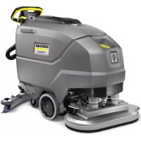


| Product type | Scrubber dryer (floor cleaner) |
| Brand | Kärcher |
| Model | BD 7075 W Classic Bp (BD 70/75 W Classic Bp) |
| Rated voltage | 24 V |
| Battery capacity | 80 Ah or 160 Ah (depending on version) |
| Average power consumption | 1270 W |
| Clean water tank volume | 75 L |
| Dirty water tank volume | 75 L |
| Working width (brushes) | 700 mm |
| Brush diameter | 356 mm |
| Brush rotation speed | 140 rpm |
| Brush ground pressure | 300 / 500 N (normal / increased) |
| Theoretical area performance | 3500 m²/h |
| Maximum slope of working area | 2% |
| Empty weight (transport weight) | 251 kg |
| Total permissible weight | 325 kg |
| Maximum water temperature | 50 °C |
| Usage type | Professional and industrial |
| Main functions | Water cleaning of flat floors, suction, adjustment of water quantity and speed, traction drive |
| Care and maintenance | Draining tanks, cleaning filters, checking suction lips and brushes, battery charging |
| Safety devices | Safety switch, key switch, deep discharge protection |
| Spare parts and accessories | Brush discs (white, natural, red, black), pads, suction bar, filters, batteries |
| Warranty | According to manufacturer's conditions, contact distributor |
Frequently Asked Questions - BD 7075 W Classic Bp Kärcher
User questions about BD 7075 W Classic Bp Kärcher
0 question about this device. Answer the ones you know or ask your own.
Ask a new question about this device
Download the instructions for your Floor cleaner in PDF format for free! Find your manual BD 7075 W Classic Bp - Kärcher and take your electronic device back in hand. On this page are published all the documents necessary for the use of your device. BD 7075 W Classic Bp by Kärcher.
USER MANUAL BD 7075 W Classic Bp Kärcher
Type: 1.127-xxx, 1.515-xxx
Chairman of the Board of Management
S. Reiser
Director Regulatory Affairs & Certification
71364 Winnenden (Germany)
Tel.: +49 7195 14-0
Fax: +49 7195 14-2212
Winnenden, 2021/02/01
Contents
General notes 12
Function 12
Intended use 12
Environmental protection 12
Accessories and spare parts. 12
Scope of delivery 12
Safety instructions 12
Description of the unit 13
Installation 14
Initial startup 15
Operation 15
Transport 17
Storage 17
Care and maintenance 17
Troubleshooting guide 18
Warranty 19
Accessories BD variant 19
Technical data 20
Declaration of Conformity 20
General notes
Read these original operating instructions and the enclosed safety instructions before using the device for the first time. Proceed accordingly.
Keep both books for future reference or for future owners.
Function
This scouring and vacuum machine is used for wet cleaning of level floors.
The device can be adjusted to suit the respective cleaning task by setting the water volume and detergent volume appropriately. The detergent dosing is adjusted via the amount added to the tank.
The working width and the capacity of the fresh and waste water tanks (see chapter "Technical data") enable effective cleaning with a long working time.
The device has a drive motor.
Note
The device can be equipped with various accessories to suit the respective cleaning task. Request a copy of our catalogue or visit our Internet website at www.kaercher.com.
Intended use
This device is suitable for commercial and industrial use, e.g. in hotels, schools, hospitals, factories, shops, offices, and rental companies. Use the device only in accordance with the information in these operating instructions.
- The device may only be used for cleaning smooth surfaces that are insensitive to water and polishing. The device is not suitable for cleaning frozen floors (e.g. in cold stores).
- The device is not suitable for use in potentially explosive environments.
- The device is approved for operation on surfaces with a maximum slope (see chapter Technical data).
Environmental protection
The packing materials can be recycled. Please dispose of packaging in accordance with the environmental regulations.
Electrical and electronic appliances contain valuable, recyclable materials and often components such as batteries, rechargeable batteries or oil, which - if handled or disposed of incorrectly - can pose a potential threat to human health and the environment. However, these components are required for the correct operation of the appliance. Appliances marked by this symbol are not allowed to be disposed of together with the household rubbish.
Notes on the content materials (REACH)
Current information on content materials can be found at: www.kaercher.com/ REACH
Accessories and spare parts
Only use original accessories and original spare parts. They ensure that the appliance will run fault-free and safely. Information on accessories and spare parts can be found at www.kaercher.com.
Scope of delivery
Check the contents for completeness when unpacking. If any accessories are missing or in the event of any shipping damage, please notify your dealer.
Safety instructions
Before using the device for the first time, read and observe these operating instructions and the accompanying brochure: Safety information for brush cleaning units spray retraction devices, No. 5.956-251.0. The device is approved for operation on surfaces with a specified limited slope (see Chapter Technical data).
WARNING
Risk of injury!
Device may tip over on sloping surfaces.
Do not operate the device on sloping surfaces.
The device may only be operated when the hood and all covers are closed.
Safety devices
CAUTION
Missing or modified safety devices!
Safety devices are provided for your own protection.
Do not bypass, remove or render ineffective any safety devices.
Safety switch
The device switches off when the safety switch is released.
Key-operated switch
Pulling the key out of the key-operated switch secures the device against unauthorised use.
Warning symbols
Observe the following warnings when handling the batteries:
| Observe notes in the instruc-tions for the battery, on the ba- tery and in these operating instructions. | |
| Wear eye protection. | |
| Keep acids and batteries away from children. | |
| Risk of explosion | |
| Fire, sparks, open flames and smoking are prohibited. | |
| Risk of acid burns | |
| First aid. | |
| Warning | |
| Disposal | |
| Do not throw batteries in the bin. |
Description of the unit
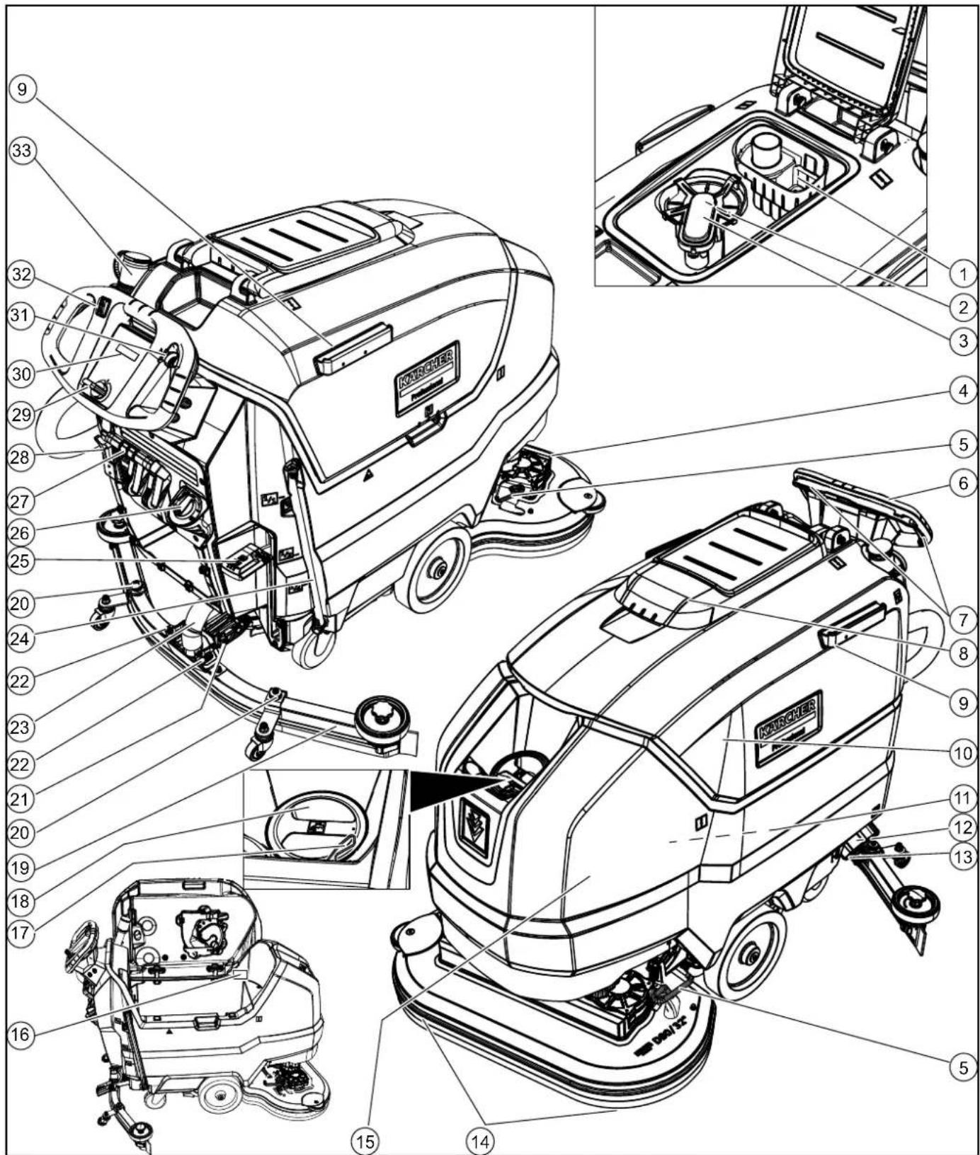
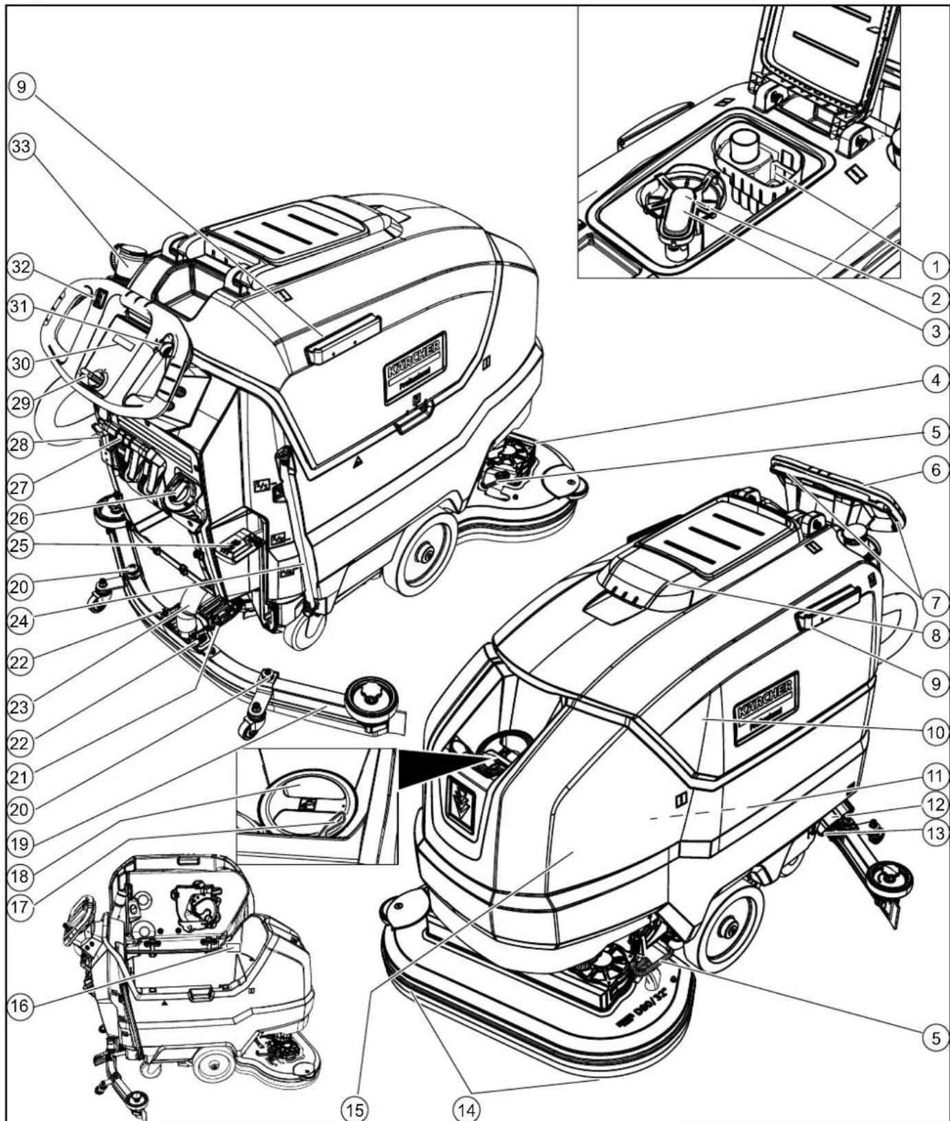
Overview of the device
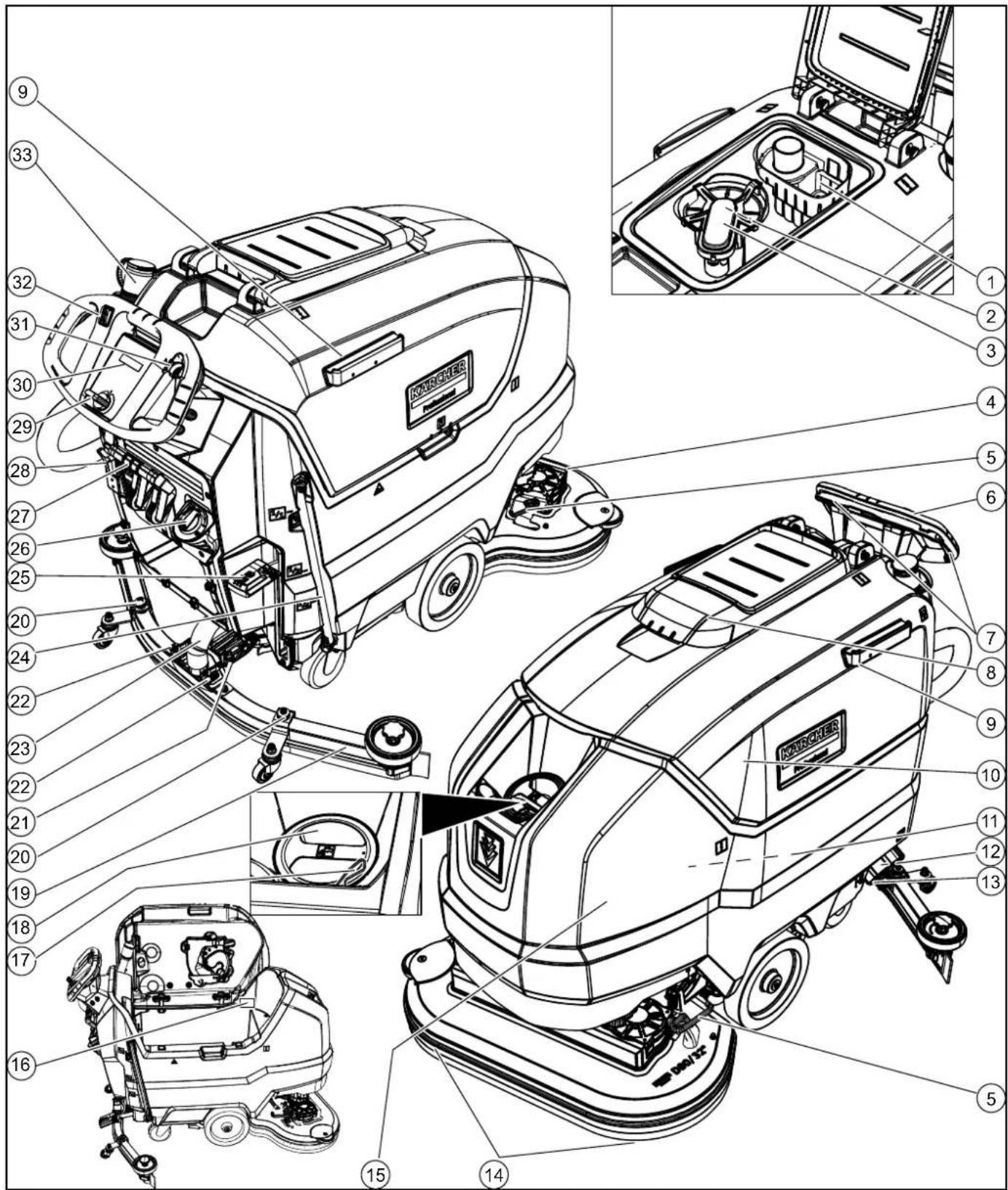
Coarse dirt filter (2) Fluff filter (3) Float (4) Cleaning head (5) Brush replacement pedal Push handle Safety switch Waste water tank cap Homebase retaining rail
10 Waste water tank 11 Battery 12 Fresh water filter 13 Fresh water tank lock 14 Disc brush 15 Fresh water tank 16 Type plate (17) Hose holder 18 Fresh water tank filling hole
(19) Suction bar 20 Suction bar height adjustment (21) Suction bar inclination adjustment 22 Wing nuts for fastening the suction bar 23 Suction hose 24 Fresh water filling level indicator 25 Fresh water drain hose 26 Cleaning head lever 27 Water volume regulation knob
Suction bar lever, battery plug connector, 29 key-operated switch, ⑤ display, ① working speed rotary knob, driving direction switch, 33 waste water tank drain hose with dosing unit
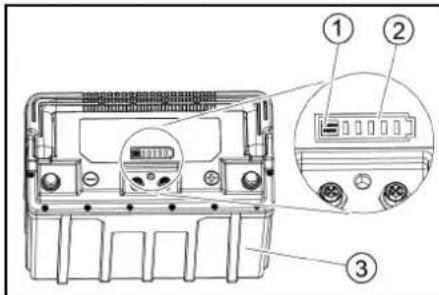
Battery
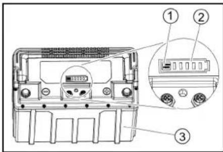
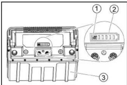
① Button, ② charge indicator, ③ battery
Colour coding
Control elements for the cleaning process are yellow. Control elements for maintenance and servicing are light grey.
Symbols on the device

Fresh water tank drain opening

Waste water tank drain opening

Increased cleaning head contact pressure

Battery access

Fresh water tank filling level (50%)

Insert the charger plug here

Lashing point

- Mop holder

ATTENTION
Incorrect socket
Risk of damage
DO NOT insert the charger plug here

Normal cleaning head contact pressure

Raise the cleaning head

Pedal for raising/lowering the cleaning head

Brush replacement pedal
- optional
Installation
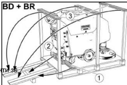
Unloading
- Remove the carton.
- Remove the straps.
- Remove the wooden blocks fastened to the pallet by screws.
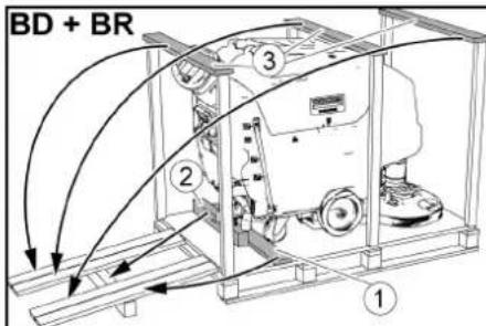
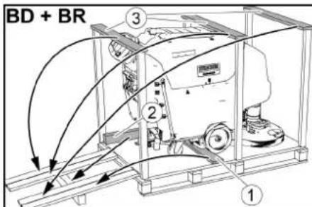
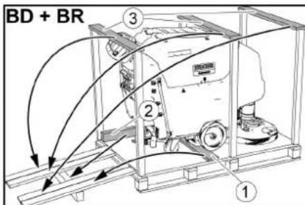
- Using the 3 upper reinforcing boards of the carton packaging and the securing board screwed laterally on the pallet, place a ramp in front of the pallet and secure it using board pallet screws.
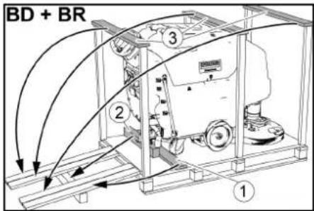
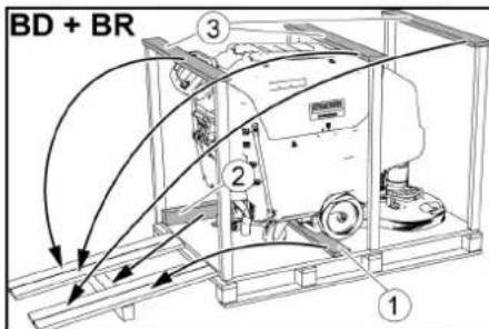
①Securing board
2Beam
③ Reinforcing board
- Push the beam that has been unscrewed from the pallet under the ramp for support and screw it into place.
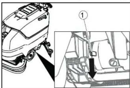
- Press the cleaning head lever down and latch it in place.
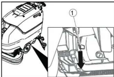
- Only for BD 80/100 and BR 85/100: Press the brake lever down.
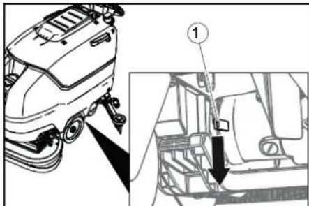
(1) Brake lever
Note
For BD 70/75 and BR 75/75, there is no brake. Releasing the brake is not necessary with this device.
- Pull the device backwards off the pallet.
- Only for BD 80/100 and BR 85/100: Press the brake lever up.
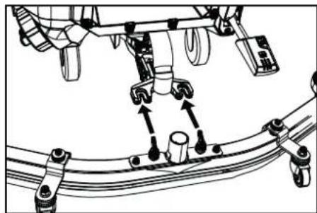
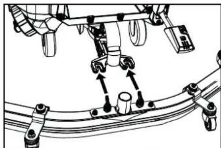
Installing the suction bar
- Insert the suction bar in the suction bar mount.
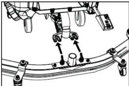
- Tighten the wing nuts.
- Fit the suction hose.
Batteries
Recommended batteries
| Device Battery | |
| BD 70/75 W Classic Bp Pack 80 Ah Li | 1 x 6.654-454.0 |
| BD 70/75 W Classic Bp Pack 160 Ah Li | 2 x 6.654-454.0 |
| BD 80/100 W Classic Bp Pack 160 Ah Li | 2 x 6.654-454.0 |
ATTENTION
Risk of damage
Using other batteries may damage the device. Only use the recommended batteries.
Installing and connecting batteries
CAUTION
Removing and installing the batteries
Unstable machine position
Ensure that the machine is positioned stably when removing and installing the batteries.
ATTENTION
Incorrect connection polarity
Destruction of the control electronics
Take care to ensure the correct polarity when connecting the batteries.
ATTENTION
Deep discharge
Risk of damage
Charge the batteries before starting the device.
- Drain the waste water.
- Pivot the waste water tank upwards.
- Disconnect the battery plug.
- Place the battery in the device as shown.
BD 80/100:
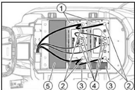
① Battery ② Battery pole ③ Spacer 150x150x65 ④ Circular connector ⑤ Spacer 90x185x335 (2 pieces on top of each other)
BD 70/75 80 Ah: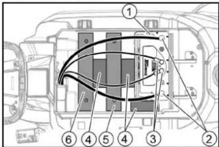
① Battery ② Battery pole ③ Circular connector ④ Spacer 150x150x65 ⑤ Additional weight, 6 plates ⑥ Additional weight, 14 plates
BD 70/75 160 Ah:
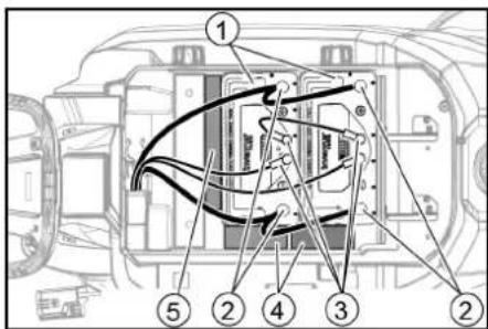
① Battery ② Battery pole ③ Circular connector ④ Spacer 150x150x65 ⑤ Spacer 155x300x60 5. Insert the spacers and additional weights as indicated.
ATTENTION
Risk of damage
If the polarity (plus and minus terminal) is reversed, the control electronics will be damaged.
Connect the red cable to the positive terminal and the black cable to the negative terminal. Observe the illustrations shown above when connecting the cables.
- Clamp the connecting cables onto the (+) and (-) battery terminals.
- For devices with two batteries, attach the connecting cable between the two batteries.
- Plug the circular connectors into the batteries.
- Connect the device-side battery connector to the battery-side battery connector. 10. Pivot the waste water tank downwards.
Note
Charge the batteries before starting up the device (see section "Charging the batteries").
Removing the batteries
CAUTION
Removing and installing the batteries Unstable machine position
Ensure that the machine is positioned stably when removing and installing the batteries.
- Turn the key-operated switch to "0" and remove the key.
- Disconnect the battery plug.
- Drain the waste water.
- Pivot the waste water tank upwards.
- Unplug all circular connections.
- Disconnect the device-end cable from the negative terminal of the battery.
- Disconnect the remaining cables from the batteries.
- If necessary, remove the spacers.
- Remove the batteries.
- Dispose of the used batteries in accordance with statutory provisions.
Initial startup
Charging the battery
DANGER
Inappropriate use of the charger Electric shock
Adhere to the mains voltage and fuse values specified on the device type plate. Only use the charger in dry rooms with sufficient ventilation.
ATTENTION
Using an unsuitable charger
Risk of damage
Do not connect the charger to the device-side battery connector.
Use only a charger suitable for the type of battery installed.
Read the operating instructions of the charger manufacturer and observe the safety instructions in particular.
The device cannot be used during the charging process.
Note
The device has deep discharge protection, i.e. the brush motor and turbine are switched off automatically when the permitted minimum capacity level is reached.
- Drive the device directly to the charger and do not drive on slopes.
- Pull out the device-side battery connector.
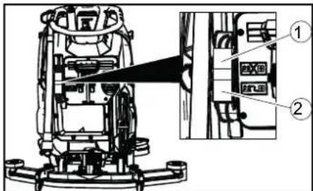
Battery plug, device side ② Battery plug, battery side
ATTENTION
Risk of damage
Do not connect the charger to the device-side battery connector.
Note
Please read the operating instructions of the charger manufacturer, especially the chapters on safety instructions! 3. Connect the battery-side battery connector to the charger.
- Plug the mains plug of the charger into the socket.
- Carry out the charging process in accordance with the operating instructions for the charger.
The charging time depends on the battery condition and the charger. When the battery is empty, the charging time is approximately:
| Charger Battery capacity | Charging time approx. |
| 6.654-483.0 80 Ah 7 hours | |
| 6.654-484.0 80 Ah 2 hours | |
| 160 Ah 4 hours |
- After the charging process is complete: a Unplug the mains plug of the charger. b Disconnect the battery connector from the charger.
c Connect the device-side battery connector to the battery-side battery connector.
Operation
ATTENTION
Risks during operation
Danger of injury
Release the safety switch in the case of danger.
Filling with operating materials
Filling fresh water
- Open the fresh water tank cap.
- Fill fresh water (max. 50°C) to the lower edge of the filling nozzle.
Note: The fresh water hose can be clamped with the hose holder during filling.
- Close the fresh water tank lock.
Notes on detergents
WARNING
Risk of damage to the device!
If unsuitable detergents are used, the device may get damaged.
Use only recommended detergents. The operator carries all increased risks relating to operational safety and increased risk of accidents if using other detergents. Use only detergents free of solvents, salt and hydrofluoric acid.
Adhere to the safety instructions stated on the detergent packaging.
Note
Do not use heavily foaming detergent.
Recommended detergents
| Application Detergent | |
| Floor maintenance cleaner extra low foaming with EU Ecolabel | APPROX. 50 C |
| Highly wetting universal cleaner | RM 756 |
| Intensive alcohol cleaner for floors and surfaces. Well-suited for hard rock such as granite | RM 755 |
| Fine stone cleaner, sur- factant-free | RM 753 |
| Universal decoater, suitable for linoleum | RM 754 |
| Acidic vending machine basic cleaner. Suitable for sanitary areas and construction cleaning | RM 751 |
| Industrial maintenance cleaner | RM 69 |
| Industrial basic cleaner and alkaline decoater | RM 752 |
| Surface disinfectant cleaner | RM 732 |
Detergent
- Fill the detergent into the fresh water tank.
Note: The cap for the fresh water tank filling hole can be used for measuring the correct quantity of detergent. It has a measuring scale marked on the inner side.
Adjusting the water volume
- Adjust the water volume via the regulating knob to suit the degree of soiling of the floor covering.
Note
Perform initial cleaning tests with a low water volume. Increase the water volume step by step until achieving the desired cleaning result.
Note
The cleaning head continues operating without a liquid supply if the fresh water tank is empty.
Adjusting the suction bar
Adjusting the inclination
The inclination must be adjusted so that the suction lips of the suction bar make even contact with the floor over the entire length of the suction bar.
- Loosen the screw.
①Screw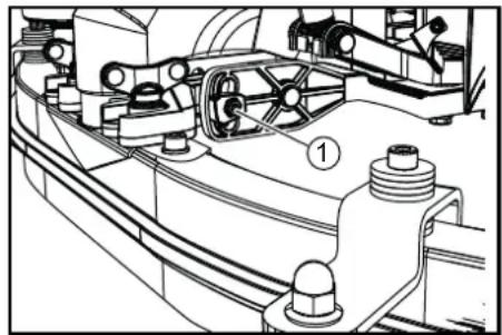
- Adjust the inclination of the suction bar.
- Tighten the screw.
Adjusting the height
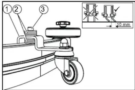
The height adjustment affects the bending of the suction lips on contact with the floor.
- Push the device a small distance forwards.
- Compare the bending of the suction lips with the figure below.
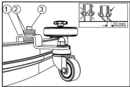
(1) Spacer roller with holder ②Washer (3)Screw 3. Unscrew the screw. 4. Insert a sufficient number of washers between the suction bar and spacer roller to create the correct bending of the suction lip. 5. Fit the remaining unused washers above the spacer roller. 6. Screw in and tighten the screw. 7. Repeat the entire procedure at the second spacer roller. 8. Push the device a small distance forwards. 9. Check the bending of the suction lips over the entire length. 10.Repeat the adjustment procedure if necessary.
Cleaning
Switching on the device
- Turn the key-operated switch to "1". The display shows the following one after the other: Period of time until the next after-sales Customer Service
- Software version, control panel
- Charging state of the battery and number of operating hours
Driving
Note
The direction of travel can be changed during the cleaning operation. This way, a certain position can be intensively cleaned by driving back and forth several times.
- Set the driving direction switch to "forward".
Cleaning
Note
The inclination and height of the suction bar can be adjusted to improve the vacuuming results (see chapter Adjusting the suction bar).
Note
When the waste water tank is full, the float switch closes the suction opening and the suction turbine runs at a higher speed. In this case, raise the suction bar and drive to the location for emptying the waste water tank. 1. Turn the working speed rotary knob to the desired value.
The speed is shown on the display during the adjustment. The display is shown in percentage of the maximum speed.
- Set the water volume at the regulating valve.
- Press the suction bar lever downwards. The suction bar lowers. Vacuuming begins.
- Press the cleaning head lever downwards, unlatch it and allow it to move upwards.
- Pull the safety switch towards the push handle. The cleaning head starts up and the device moves at the set speed.
Increasing the brush contact pressure
- Let go of the safety switch.
- Lift the cleaning head lever up with your hand and latch it towards the right.
Finishing operation
Finishing cleaning
- Let go of the safety switch.
- Press the cleaning head lever down and latch it in place.
- Continue moving a short distance. The residual water is vacuumed up.
- Lift the suction bar.
The suction continues to run for 10 seconds.
- Turn the key-operated switch to "0".
- Charge the battery if necessary.
Draining the waste water
WARNING
Environmental pollution!
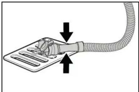
Environmental pollution due to improper disposal in waste water. Observe the local waste water treatment regulations. 1. Remove the drain hose from the support and lower it over a suitable collecting device.
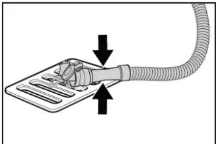
- Press the dosing unit together or kink the hose.
- Open the dosing unit cover.
- Drain the waste water. Regulate the water volume by pressing or kinking.
- Rinse the waste water tank with clear water.
Draining fresh water
- Pull off the filling level indicator hose and swivel it down.
Quickly draining fresh water
- Unscrew the fresh water tank cap.
- Allow the fresh water to drain away.
- Fit the fresh water tank cap and screw into place.
Note: Take care to ensure that the hose connection in the fresh water tank cap is positioned at the lowest point in the tank after screwing the cap in place.
Transport
DANGER
Driving on slopes
Risk of injury
Observe the maximum permissible inclination when driving the device on slopes for loading and unloading purposes (see chapter "Technical data"). Drive slowly.
CAUTION
Failure to observe the weight
Risk of injury and damage
Be aware of the weight of the device during transport.
Only load the device with the assistance of another person or by using the drive.
- Press the cleaning head lever down and latch it in place.
- Raise the suction bar.
- Turn the key-operated switch to "1".
- Select the travel direction at the travel direction switch.
- Pull the safety switch towards the push handle.
- When transporting in vehicles, secure the device against slipping and tipping over according to the applicable guidelines.
7. First fit the strap under the waste water tank.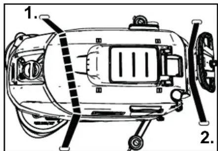
Storage
CAUTION
Risk of injury and damage!
The device may tip over on sloping surfaces.
Be aware of the weight of the device during storage.
ATTENTION
Frost
Destruction of the device through freezing water
Drain all water from the device.
Store the device in a frost-free location.
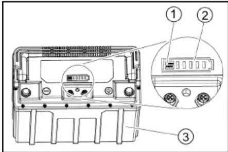
This device may only be stored indoors. - Before prolonged storage: 1. Bring the battery/batteries to a state of charge between 30% and 50%. 2. Disconnect the charger from the battery connector. 3. Press the button on the battery for 20 seconds to put the battery into sleep mode.
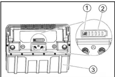
①Button (2)Charge indicator ③ Battery
The LEDs of the charge indicator all light up and go out one after the other. The charge indicator will now no longer react when the button is pressed briefly.
Note
For devices with multiple batteries, this procedure only needs to be carried out on one battery. The other batteries take over the sleep mode automatically.
Care and maintenance
△DANGER
Risk of injury!
The device may start moving unexpectedly and cause injury.
Turn the key-operated switch to "0" and remove the key before performing any work on the device.
Pull out the charger mains plug.
- Drain and dispose of the waste water and fresh water.
Safety inspection/maintenance contract
You can agree on regular safety inspections or close a maintenance contract with your dealer. Please seek advice on this.
Maintenance intervals
Each time after use
ATTENTION
Improper cleaning
Risk of damage.
Do not spray the device with water. Do not use aggressive cleaning agents.
A detailed description of the individual maintenance work is provided in Chapter Maintenance work.
Drain the waste water. - Rinse the waste water tank with clear water. - Clean the exterior of the device using a damp cloth, wetted with a mild washing lye. - Check the fluff filter and clean if required. Clean the coarse dirt filter. Clean the suction lips, check for wear and adjust the height or replace if necessary. - Check the disc brushes for wear and replace if necessary. Charge the battery.
- If the charging state of the battery is below 50% , charge the battery fully and without interruption.
- If the charging state of the battery is above 50% , only recharge the battery if the entire operating duration will be required when next used.
Monthly
A detailed description of the individual maintenance work is provided in the chapter "Maintenance Work".
- Drain the fresh water tank and flush out deposits.
- Clean the fresh water filter.
- Clean the float and fluff filter.
- Check battery poles for oxidation, brush off if necessary. Make sure the connection cables are firmly in place.
- Clean the seals between the waste water tank and the cover, check for leaks and replace if necessary.
- For longer periods of disuse, shut down the device when the batteries are fully charged. Fully charge the battery at least once a month.
Annually
- Have the prescribed inspection performed by Customer Service.
Maintenance work
Turn over or replace the worn suction lips
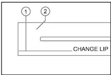
The suction lips must be turned over or replaced when they have worn down to the wear mark.
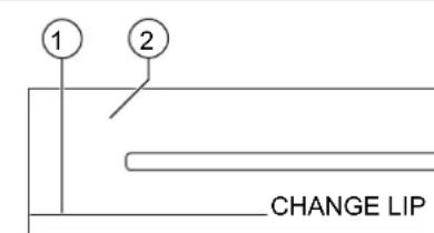
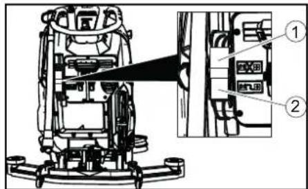
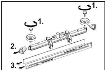
T Wear mark Suction lip 1. Remove the suction bar. 2. Unscrew the star handles.

- Pull off the plastic parts.
- Pull off the suction lips.
- Push in the turned over or new suction lips.
- Push on the plastic parts.
- Screw in and tighten the star handles.
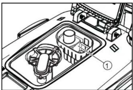
Cleaning the coarse dirt filter
- Open the waste water tank cover.
Coarse dirt filter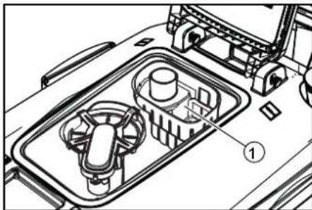
- Pull the coarse dirt filter upwards and off.
- Rinse off the coarse dirt filter under running water.
- Reinsert the coarse dirt filter into the waste water tank.
Cleaning the fresh water filter
- Drain the fresh water (see Chapter Draining fresh water).
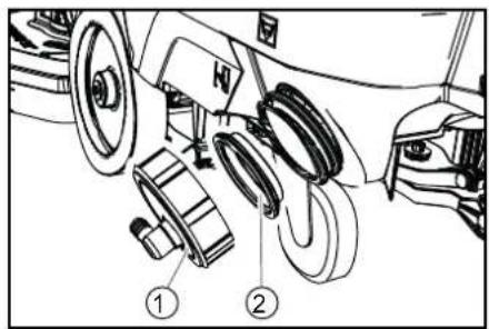
- Unscrew the fresh water tank lock.
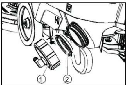
① Fresh water tank lock
(2) Fresh water filter 3. Pull out the fresh water filter and rinse with clean water. 4. Insert the fresh water filter. 5. Fit the fresh water tank lock.
Note: Take care to ensure that the hose connection in the fresh water tank cap is positioned at the lowest point in the tank after screwing the cap in place.
Clean the float and fluff filter
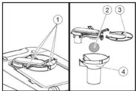
- Open the waste water tank cover.
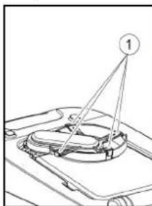
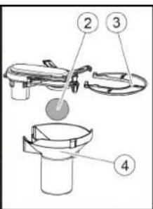
① Latching hooks ②Float ③Fluff filter ④ Float housing 2. Release the latching hooks. 3. Pull the float housing downwards and off.
- Remove the float from the float housing and clean it.
- Remove the fluff filter and clean it.
- Assemble all parts in the reverse order.
Replacing the disc brushes
- Raise the cleaning head.
- Press the brush replacement pedal down, beyond the zone of resistance.
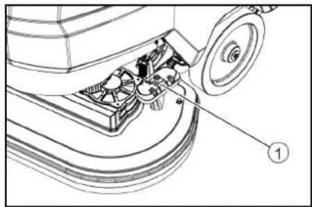
Brush replacement pedal. 3. Pull the 1st disc brush sideways and out from underneath the cleaning head. 4. Hold the new disc brush under the cleaning head, then press upwards and latch it into position. 5. Repeat the procedure for the 2nd disc brush.
Troubleshooting guide
DANGER
Risk of injury!
The device may start moving unexpectedly and cause injury.
Turn the key-operated switch to "0" and remove the key before performing any work on the device.
Pull out the charger mains plug.
- Drain and dispose of the waste water and fresh water.
- Contact Customer Service in the case of malfunctions that cannot be corrected using this table.
Battery status indicator
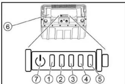
Status LED (2) Indicator LED 1, Indicator LED 2, Indicator LED 3, Indicator LED 4, Battery, Button
- Press the button for 5 seconds.
No LED lights up: Charge the battery.
The status LED lights up green: Together, all 5 LEDs indicate the battery's charging state. - The status LED lights up red: The indicator LEDs indicate a malfunction. Malfunctions described in the following table can be remedied by the user. Contact KARCHER Customer Service for all malfunctions indicated not described above.
(1) (2) (3) (4) (5) Cause Rectification
| red - - | - - The battery is too hot. Allow the battery to cool down. | |
| red - - | green The battery manage ment system is too hot. | Allow the battery to cool down. |
| red | - - green - | The battery is too cold for charging. Move the device to a warmer place and wait until the battery has warmed up. |
| red - - | green green The current consumption during charging is too high. | Unplug the mains plug of the charger. Wait 10 seconds. Re-insert the mains plug. If the malfunction is displayed again, replace the charger. |
| Switch off the device. If the malfunction occurs again after switching on, look for the fault in the device. | ||
| red - green - short-circuit. Check all batteries connections. | ||
| red - green green - Cell voltage too low during dis-charge. Charge the battery. | ||
| red - green green cell voltage too high during charging. Discharge the battery to 20% remaining capacity. Then charge the battery. | ||
| red green - - green The battery voltage is too low. Charge the battery. | ||
Faults that are not displayed
| (1) (2) | (3) (4) | (5) Cause Rectification | |||
| red green | green - green | - | Malfunction during charging process. | Unplug the mains plug of the charger. Wait 10 seconds. Re-insert the mains plug. If the malfunction is displayed again, replace the charger. | |
| red green | green - green | green | |||
| red green | green - - T | the battery is too cold to output power. | Move the device to a warmer place and wait until the battery has warmed up. | ||
| red | green | green | green | Power output malfunction. | Switch off the device. If the malfunction persists, contact Customer Service. |
| Malfunction Rectification | |
| The device cannot be started | 1. Turn the key-operated switch to "1".2. Unlock the emergency stop button on the control panel by turning it. (Note: not all device versions are equipped with an emergency stop button)3. Actuate the safety switch.4. Insert the battery plug.5. Check the battery and charge if necessary.6. Check that the battery terminals are correctly connected. |
| The water volume is insufficient | 1. Check the fresh water filling level and fill the tank if necessary.2. Increase the water volume at the water volume regulating knob.3. Clean the fresh water filter.4. Check the hoses for clogging and clean if necessary. |
| The suction performance is too low | 1. Shut down the device and drain the waste water.2. Clean the seals between the waste water tank and the cover, check for leaks and replace if necessary.3. Check that the suction hose is correctly connected to the waste water tank.4. Check the fluff filter for soiling and clean if necessary.5. Clean the suction lips at the suction bar, turn over or replace if necessary.6. Check that the cap on the waste water drain hose is closed.7. Check the adjustment of the suction bar.8. Check the suction hose for clogging and clean if necessary. The white marking on the hose must lie at the retaining clip when the suction hose is re-inserted.9. Check the suction hose for leaks and replace if necessary. |
| The cleaning results are unsatisfactory | 1. Reduce the driving speed.2. Check the brushes for wear and replace if necessary.3. Check the suitability of the brush type and detergent used. |
| The suction turbine runs at an increased speed | 1. Drain the waste water.2. Clean the float.3. Check the fluff filter and clean if necessary.4. Check the suction hose for clogging and clean if necessary.5. Check the suction bar for clogging and remove any clogging if necessary |
| The brushes do not rotate | 1. Check if the brushes are blocked by a foreign body and remove the foreign body if necessary. |
| The device vibrates during cleaning | 1. Use a softer brush. |
| The "Battery disconnected" LEDs, 80% and 100% on the charger light up several times in succession | 1. The charger is in the recharging phase. In this phase, the state of charge of the individual battery cells is equalised. A fault is only present if the "Battery disconnected" LED lights up continuously. |
| The battery cannot be charged | The battery is deeply discharged and cannot be woken up by the charger.1. Connect the charger to the mains connection and to the battery.2. Press the button on the battery for longer than 5 seconds. The battery is woken up and the charging process starts. |
Warranty
The warranty conditions issued by our relevant sales company apply in all countries. We shall remedy possible malfunctions on
your appliance within the warranty period free of cost, provided that a material or manufacturing defect is the cause. In a warranty case, please contact your dealer (with
the purchase receipt) or the next authorised customer service site. (See overleaf for the address)
Accessories BD variant
| Description BD 70/75 | part no. | BD 80/100 part no. | Description |
| Disc brush, white (soft) | 4.905-011.0 | 4905-030.0 | For cleaning lightly soiled or sensitive floors |
| Disc brush, natural colour (soft) | 4905-012.0 | 4905-031.0 | Made of natural fibres for cleaning and polishing |
| Disc brush, red (medium, standard) | 4905-010.0 | 4.905-000.0 | For use in all common cleaning tasks |
| Disc brush, black (hard) | 4905-013.0 | 4905-032.0 | For heavy soiling and basic cleaning, only for non-sensitive surfaces |
| Pad drive board | 4762-590.0 | 4762-447.0 | For cleaning with pads, with quick-change coupling and centre-lock |
| Pad, white – 6.371-331.0 For polishing floors | |||
| Pad, red (medium soft) 6.369-003.0 | 6371-147.0 | For cleaning all floors | |
| Pad, green (medium hard) | 6.369-002.0 | 6371-148.0 | For cleaning heavily soiled floors and for basic cleaning |
| Pad, black (hard) 6.369-001.0 6371 | -169.0 | For stubborn soiling and for basic cleaning | |
| Pad, brown (SPP) | 2.639-290.0 | 2639-288.0 | For protective film application on hard and elastic surfaces |
Technical data
| BD | BD | |
| 70/75 | 80/ | |
| W | 100 W | |
| Clas- | Clas- | |
| sic | sic | |
| Bp | Bp |
Device performance data
| Nominal voltage V 24 24 | |||
| Battery capacity Ah (5 h) | 80 / 160 | 160 | |
| Mean power input W | 1270 | 1320 | |
| Driving motor pow- er | 250 | 300 | |
| Suction turbine power W | 500 | 500 | |
| Brush drive power W | 2 x 500 | 2 x 500 | |
| Theoretical surface performance | m2/h | 3500 | 4000 |
| Fresh water tank capacity | 1 | 75 | 100 |
| Waste water tank capacity | 1 | 75 | 100 |
| Water temperature max. | °C | 50 | 50 |
| Water pressure max. | bar | 0,06 | 0,06 |
| Aisle turning width | mm | 1550 | 1650 |
| Max. working area slope | % | 2 | 2 |
Vacuuming
| Suction performance, air quantity | l/s | 24 24 | |
| Suction performance, vacuum | kPa (mbar) | 16 (160) | 16 (160) |
Cleaning brushes
| Working width | mm | 700 | 800 |
| Brush diameter | mm | 356 | 410 |
| Brush speed | 1/min | 140 | 140 |
| Brush contact pres- sure | 300 / 500 | 400 / 680 | |
Dimensions and weights
| Approved total weight | kg | 325 | 435 |
| Net weight (transport weight) | kg | 251 | 325 |
| Battery compartment dimensions | mm | 575 x 380 | 622 x 384 |
Determined values in acc. with EN 60335-2-72
| Overall vibration value | m/s2 | <2,5 | <2.5 |
| Uncertainty K | dB(A) | 0,2 | 0,2 |
| BD | BD | |
| 70/75 | 80/ | |
| W | 100 W | |
| Clas- | Clas- | |
| sic | sic | |
| Bp | Bp |
Sound pressure level LpA dB(A) 65 65
Uncertainty KpA dB(A) 2 2
Sound power level dB(A) 81 81
LWA + K uncertainty WA
Subject to technical modifications.
Declaration of Conformity
EU Declaration of Conformity
We hereby declare that the machine described below complies with the relevant basic safety and health requirements in the EU Directives, both in its basic design and construction as well as in the version placed in circulation by us. This declaration is invalidated by any changes made to the machine that are not approved by us.
Product: Floor cleaner
Type: 1.127-xxx, 1.515-xxx
Currently applicable EU Directives
2006/42/EC (+2009/127/EC)
2014/30/EU
2014/53/EU (TCU)
Harmonised standards used
EN 60335-1
EN 60335-2-72
EN 55012: 2007 + A1: 2009
EN 61000-6-2: 2005
EN 62233: 2008
TCU
EN 301 511 V12.5.1
EN 300 440 V2.1.1
EN 300 328 V2.2.2
EN 300 330 V2.1.1
National standards used
The signatories act on behalf of and with the authority of the company management.

H. Jenner
Chairman of the Board of Management
S. Reiser
Director Regulatory Affairs & Certification
Documentation supervisor:
S. Reiser
Alfred Kärcher SE & Co. KG
Alfred-Karcher-Str.28-40
71364 Winnenden (Germany)
Ph.: +49 7195 14-0
Fax: +49 7195 14-2212
Winnenden, 2021/02/01
Declaration of Conformity (UK)
We hereby declare that the product described below complies with the relevant provisions of the following UK Regulations, both in its basic design and construction as well as in the version put into circulation by us. This declaration shall cease to be valid if the product is modified without our prior approval.
Product: Floor cleaner
Type: 1.127-xxx, 1.515-xxx
Currently applicable UK Regulations
S.I. 2008/1597 (as amended)
S.I. 2016/1091 (as amended)
S.I. 2017/1206 (as amended) (TCU)
Designated standards used
EN 60335-1
EN 60335-2-72
EN 55012: 2007 + A1: 2009
EN 61000-6-2: 2005
EN 62233: 2008
TCU
EN 301 511 V12.5.1
EN 300 440 V2.1.1
EN 300 328 V2.2.2
EN 300 330 V2.1.1
National standards used
The signatories act on behalf of and with the authority of the company management.
H.Jenner
Chairman of the Board of Management

S. Reiser
Director Regulatory Affairs & Certification
Documentation supervisor:
S. Reiser
Alfred Kärcher SE & Co. KG
Alfred-Karcher-Str.28-40
71364 Winnenden (Germany)
Ph.: +49 7195 14-0
Fax: +49 7195 14-2212
Winnenden, 2021/02/01
Contents
General notes. 21
Function 21
Continue aspiration for another 10 seconds.
2006/42/EC (+2009/127/EC)
2014/30/EU
2014/53/EU (TCU)
H. Jenner Chairman of the Board of Management
S. Reiser Director Regulatory Affairs & Certification
Responsible for documentation:
S. Reiser
Alfred Kärcher SE & Co. KG
Alfred-Karcher-Str. 28-40
71364 Winnenden (Germany)
Tel.: +49 7195 14-0
Fax: +49 7195 14-2212
Winnenden, 01/02/2021
Index
Tip: 1.127-xxx, 1.515-xxx
Chairman of the Board of Management
S. Reiser
Director Regulatory Affairs & Certification
71364 Winnenden (Germany)
Tel.: +49 7195 14-0
Fax: +49 7195 14-2212
Winnenden, 01/02/2021
Contents
Environmental protection. 40
Fresh water tank drain opening

Waste water tank drain opening

Product: floor cleaner Type: 1.127-xxx, 1.515-xxx
Chairman of the Board of Management
Director Regulatory Affairs & Certification
71364 Winnenden (Germany)
Tel.: +49 7195 14-0
Fax: +49 7195 14-2212
Winnenden, 2021/02/01
Table of contents
General notes. 49
Operation 49
Intended use. 49
Type: 1.107-xxx, 10515-xxx
Applicable EU Directives
2006/42/EC (+2009/127/EC)
2014/30/EU
2014/53/EU (TCU)
Director Regulatory Affairs & Certification
Documentation responsible:
S. Reiser
Alfred Kärcher SE & Co. KG
Alfred-Karcher-Str.28-40
71364 Winnenden (Germany)
Tel.: +49 7195 14-0
Fax: +49 7195 14-2212
Winnenden, 01/02/2021
Indices
General information. 59
Function 59
Disassemble the batteries
CAUTION
Type: 1.127-xxx, 1.515-xxx
2006/42/EC (+2009/127/EC)
2014/30/EU
2014/53/EU (RED)
Chairman of the Board of Management
S. Reiser
Director Regulatory Affairs & Certification
Winnenden, 01/02/2021
Contents
General notes 68
Function 68
Correct use 68
Environmental protection 68
Insert the charger plug here

Attachment point

*Mop holder

NOTE

Wrong slot
Risk of damage
Do NOT insert the charger plug here
Normal pressure of the cleaning head

Pedal raise/lower cleaning head

Pedal brush change
* option
Assembly
Reading
Hazardous situation during operation
Type: 1.127-xxx, 1.515-xxx
2006/42/EF (+2009/127/EF)
2014/30/EU
2014/53/EU (TCU)
Use of harmonized standards
EN 60335-1
EN 60335-2-72
EN 55012: 2007 + A1: 2009
EN 61000-6-2: 2005
EN 62238:2008
TCU
EN30151V12.3
EN 300 440 V2.1.1
EN 300 328 V2.2.2
EN 300 330 V2.1.1
Applied national standards
-
Chairman of the Board of Management
S. Reiser
Director Regulatory Affairs & Certification
71364 Winnenden (Germany)
Tel.: +49 7195 14-0
Fax: +49 7195 14-2212
Winnenden, 2021/02/01
Contents
General notes 77
Function 77
Intended use 77
Environmental protection 77
Wrong place to plug in
Type: 1.127-xxx, 1.515-xxx
Applicable EU Directives
2006/42/EC (+2009/127/EC)
2014/30/EU
2014/53/EU (TCU)
Harmonized standards applied
EN 60335-1
EN 60335-2-72
EN 55012: 2007 + A1: 2009
EN 61000-6-2: 2005
EN 62233: 2008
TCU
EN 301511 V12.5.1
EN 300 440 V2.1.1
EN 300 328 V2.2.2
EN 300 330 V2.1.1
H. Jenner Chairman of the Board of Management
S. Reiser Director Regulatory Affairs & Certification
71364 Winnenden (Germany)
Tel.: +49 7195 14-0
Winnenden, 2021/02/01
Contents
General information 86
Function 86
www.kaercher.com/REACH
Type: 1.127-xxx, 1.515-xxx
H. Jenner Chairman of the Board of Management
S. Reiser Director Regulatory Affairs & Certification
Authorized documentation representative:
S. Reiser
Alfred Kärcher SE & Co. KG
Alfred-Karcher-Str. 28-40
D-71364 Winnenden (Germany)
Phone: +49 7195 14-0
Fax: +49 7195 14-2212
Winnenden, 2021-02-01
Contents
General instructions 95
Operation 95
Type: 1.127-xxx, 1.515-xxx
Applicable EU directives
2006/42/EC (+2009/127/EC)
2014/30/EU
2014/53/EU (TCU)
H. Jenner Chairman of the Board of Management
S. Reiser Director Regulatory Affairs & Certification
71364 Winnenden (Germany)
Tel.: +49 7195 14-0
The device must be disposed of in accordance with the regulations.
According to the disposal regulations, the weight of the device must be taken into account.
CAUTION
Nayeros
KataoToPoHn Tns OuaKeuHc ano TAYWmuEvo Vepo
EKKEVWOTe TEAEIWc Tn OUAKEUN ano VEPO. ΦUALATE IN OUAKEUN OE EVAV Xwpo Xwpi TAYER.
H ouokeun autn ettpetetai va attoekeutai mvo e oowepikouc xwpouc. Piv aTó eYáNδiApKεia aTOrθηκεuαŋs: 1.ΦopriTe TIG mTatapieC Oe βaθμo μεtaδu 30% KAI 50%.
- ATOOUVBcTe Tov oOPTiOn aTo TO βσσµ mTAPias.
- PIIeOTo TAnKToPO TcS MtTApiaG yia 20 EeutePoAeTTa Wote N MtTApia va TeTei OE KATAOaON npepiaC
1nKtpo ② Auxvia kataoatao ngs opption ③ Mnatapia
Avabouv ola ta LED poptionc kai katotiv 0hivouv diaoxika. Tn ouvexia n evdiig npptiongs evavtip a TIAOV,OTAV TIECTE OUVTOA TO TAIKTPO.
Yrro8e1n
H.Jenner Chairman of the Board of Management
S. Reiser Director Regulatory Affairs & Certification
YTTUVOCTEVIKOUPaKEAouS. Reiser
Alfred Kärcher SE & Co. KG
Alfred-Karcher-Str.28-40
71364 Winnenden (Germany)
Tel: +49 7195 14-0
Fax: +49 7195 14-2212
Winnenden, 2021/02/01
Table of contents
General safety instructions 114
Function 114
Type: 1.127-xxx, 1.515-xxx
2006/42/EC (+2009/127/EC)
2014/30/EU
2014/53/EU (TCU)
H.Jenner Chairman of the Board of Management
S. Reiser Director Regulatory Affairs & Certification
Winnenden, 2021/02/01
Table of contents
General safety instructions 122
Function 122
Intended Use 122
Rotary Sprayers 123
Accessories and Spare Parts 123
Scope of Delivery 123
Safety Regulations 123
Description of the Device 124
Installation 125
Commissioning 126
Operation 127
Transport 128
Storage 128
Maintenance and Servicing 128
Troubleshooting 130
Warranty 131
PpHaadnHexHOCTn, BapnaHT BD. 132
Texnueckx xapaKTepcntukn 132
Декларачи O COOTBETCTBNN CTaHdapTaM EC. 132
06zne yka3aHn
IpeepnepBbIM npMHeHHeM yctpoiCTBa 03HaKOMMTbcrC
daHHoOpnHaNbHoH NHCpKneH no 3KcNpyatauN n npnaRaembIMyKa3aHmMn NO TexHke 6e30NaChOCTN. DeiCTBOBaTb B COOTBETCTBN C HmN.CoxpaHrTa o6 bpoUHpbl dJaIbHeIWeero nOnb3OBaHn IIN dIaCleDyUoEro BnaDeIbua.
Функеля
3TaNoIOMOHO-BCaCbBaHOUaMaIINHa npEdHa3NaueHa DnBnJXHoOuNCTKn POBbIX NIOOB.
IocpeCTBOM perynipOBK KOINueCTBa BOdbI MIOUoero cpeCTBa MaUNHa MOKeT 6bITb HAcTpoEA Ha BbINOpHeHne COOTBeTCTByIOSe 3aDaun. Do3npObaHne MOUoero cpeCTBa perynipyeTc pyTeMe rOdoabnEHN B6ak.
Paboya shnpunha n BmecTnMoCTb 6aKOB IJNACTOINrpa3HOBbI (CM. rnaBy
TexHuueckue xapaKmepucmuK) 06eCneuBAIO TΦΦeKTnBHyOuNCTky npi IPOdoJXnTeJBHom NcNoJIb3OBAHIN. YCTpOJCTBO OCHaUeHO TAgOBbIM DBuRatJeM.
PpumeyaHue
B coomemcmuu c ebinoHReMoU 3adaeu ycmpoucmeo Moxem bimb ochaueHO pa3hbuMu npuHaJeXHoCmMu. Cnpauuueaume haw kamaioe unu rocemume haw caum e Hmepheme www.kaercher.com.
IcnoJb3ObaHnne nHa3HaueHnIO
DaHHoe ycTpoIcTBo NOxOHT DnJ KOMMepueCKOrN IN POMbIuJeHHoro HcNoIb3OBAHnA, HApPmEp B RoCTINHuaX, UkoJax, BoJIbHuaX, fAbpIkaX, MaRa3InHax, Ofncax N CdaBaemBix B apeHy nOmeuHnx. IcNoIb3ObaTb DaHHoe ycTpoIcTBo NCKIIuOHTeJIbHO B COOTBeTCTBnC yKa3aHnA M, CoDEpKaaUMnC B DaHHo IHCTpykUnn IO 3KcIIyataun.
Keep away from hot surfaces.
The device is allowed to be operated only when the lid and all covers are closed.
Protective devices CAUTION
Missing or modified protective devices!
Protective devices are intended for your protection. Do not bypass, remove, or render protective devices inoperative.
Protective switch
When the protective switch is triggered, the device switches off.
Locking switch
When the button is pulled, the device locks against unauthorized use.
Warning symbols
When handling batteries, the following warnings must be observed:

Follow the instructions contained in the battery and charger instructions, as well as in these operating instructions.

Use eye protection.

Keep children away from the battery and electrical equipment.

Explosion hazard

Open, open, light up, smoking is prohibited.

Danger of chemical burns

First aid.

Warning
Do not throw the vacuum cleaner into the trash container.
Disposal
Device description
Device overview
①Filter for dirty water ②Bristle filter 3Float (4)Cleaning head ⑤Replacement brush ⑥Handle ⑦Power switch. Tank lid for dirty water
Support handle for Homebase 10 Vac for dirty water 1)Battery ⑫Clean water filter 3Tank lock for clean water 14Disc brush (15)Tank for clean water 16Filter table
17Filling opening of tank for clean water (19)Suction hose 20 Suction hose height adjustment ② Suction hose tilt adjustment 23 Bracket for suction hose attachment
23Suction hose 24 Clean water level indicator Suction hose for clean water 25 Cleaning head handle Flow regulator 77 Suction hose handle 28Battery cover 29Key switch 00nncnn 10Swivel handle for speed adjustment 32 Direction switch for movement 3Suction hose for dirty water with discharge device
Battery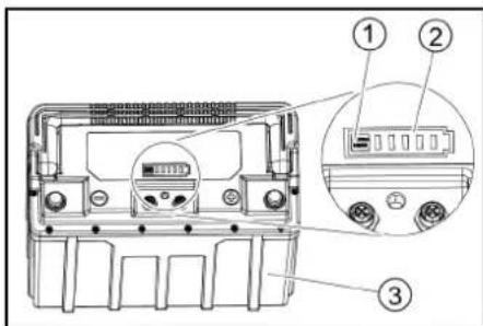
(1)Button ② Charge status indicator ③Battery
Color coding
Control elements for the process are colored white. The control elements for the technical service are made in gray.
Symbols on the device

Drain hole of the empty tank

Drain hole of the loaded tank

Increased pressure when the head is installed

Access to the accumulator

Empty tank fill level (50%)

Insert the charging device plug here

Attachment point

*Cylinder head

WARNING
Incorrect socket for connection
Danger of damage: do not insert the charging device here

Normal pressure when the head is installed

Cylinder head removed

Operation/start-up of the device

Brush replacement mode
- ONUAR
Installation
Unpacking
- Remove the cardboard packaging.
- Remove the cross-shaped fastening straps.
- Open the wooden wedges secured with screws on the pallet.
- Place the frame in front of the pallet using the 3 upper fastening boards of the cardboard packaging and the fixing board, screwed across the pallet, and secure with self-tapping screws.
①Fixing board ②Wooden beam ③Fastening board 5. Slide the wooden beam under the pallet, position the frame, and secure with screws in order. 6. Lower the cleaning head lever and secure it on the right. 7. Only for BD 80/100 and BR 85/100: Press the brake lever down.
①Brake lever
Note
In BD 70/75 and BR 75/75, there is no brake. The device does not require brake equipment. 8. Remove the device from the pallet. 9. Only for BD 80/100 and BR 85/100: Release the brake lever upward.
Installing the suction hose
1. Insert the suction hose into the suction hose holder.
- Tighten the drum bolts.
- Connect the suction hose.
Batteries
Recommended batteries
| Устroyецko AkkymеляТорн ая батеря | 1 x 6.654-454.0 |
| BD 70/75Вт Classic Bp Pack 80 Aч Li | |
| BD 70/75Вт Classic Bp Pack 160 Aч Li | 2 x 6.654-454.0 |
| BD 80/100Вт Classic Bp Pack 160 Aч Li | 2 x 6.654-454.0 |
WARNING
Risk of damage
If other battery packs are used, this may lead to damage to the device. Use only the recommended battery packs.
Installing and connecting the battery packs
CAUTION
Removing and installing the batteries
Unstable position of the machine. When removing and installing the batteries, make sure the machine is in a stable position.
WARNING
Reversing the polarity
Destruction of the control electronics. When connecting the battery, ensure correct polarity.
WARNING
Danger of damage when connecting the device to the battery.
1. Remove the dirty water. 2. Fold the dirty water tank upwards. 3. AVOID CONTACT WITH THE BATTERY. 4. Insert the battery into the device as shown in the figure.
BD 80/100: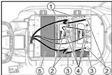
①Battery ②Battery compartment ③Spacer 150x150x65 ④Round plug ⑤Spacer 90x185x335 (2 pcs. one on top of the other)
BD 70/75 80 Ah: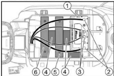
1Battery ②Battery compartment 3Round plug 4Spacer 150x150x65 ⑤Additional weight, 6 plates ⑥Additional weight, 14 plates
BD 70/75 160 Ah: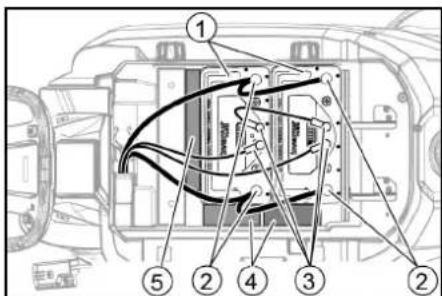
(1)Battery ②Battery compartment 3Round plug (4)Spacer 150x150x65 (5)Spacer 155x300x60
5. Insert the spacers and additional weights as indicated.
ATTENTION
Danger of damage
If the poles (positive and negative) are reversed, this will lead to damage to the electronic control unit.
Connect the red cable to the positive pole and the black cable to the negative pole. When connecting the cables, follow the figures above.
6. CONNECT THE CONNECTOR CABLES TO THE BATTERY POLES (+) AND (-). 7. WITH TWO BATTERIES, CONNECT THE CONNECTOR CABLE BETWEEN THE TWO BATTERIES. 8. INSERT THE ROUND PLUGS INTO THE BATTERIES. 9. CONNECT THE BATTERY PLUG ON THE DEVICE SIDE WITH THE BATTERY PLUGS ON THE BATTERY SIDE.
10. Open the battery compartment cover.
Note
Before operating the device, charge the batteries (see section "Charging the batteries").
Removing the batteries
CAUTION
Removing and installing the batteries
Unstable position of the machine. When removing and installing the batteries, make sure the machine is in a stable position.
- Set the key switch to the "0" position and remove the key from the lock. 2. Disconnect the battery. 3. Drain the water.
- Tilt the battery compartment cover upward.
- Disconnect all round connectors.
- Disconnect the cable from the negative terminal of the battery.
- Disconnect the remaining cables from the battery. 8. If necessary, remove the supply.
- Remove the batteries. 10. Dispose of used batteries in accordance with applicable regulations.
Commissioning
Charging the battery. Danger.
Do not use the device for purposes other than its intended use. Protect it from electric shock.
Observe the mains voltage and the nominal fuse rating indicated on the device's rating plate. Use the charging device only in dry rooms with sufficient ventilation.
WARNING
Use of an unsuitable charging device
Risk of damage
Do not connect the charging device to the battery terminals on the device side.
Use only the charging device that matches the type of batteries installed.
You should familiarize yourself with the operating instructions for the charging device
and pay special attention to the safety instructions.
THE DEVICE MUST NOT BE USED WHILE CHARGING.
Note
The device is equipped with protection against deep discharge, meaning that when the minimum permissible charge level is reached, the pump and turbine switch off.
- Move the device to the charging device, avoiding inclined surfaces.
2. REMOVE THE BATTERY FROM THE DEVICE.
If the suction cups are worn to the wear mark, they must be turned over or replaced.
①Wear mark ②Suction cup 1. Remove the suction cup. 2. Unscrew the mushroom-shaped knobs.
- Remove the paste parts. 4. Remove the suction cups. 5. Insert the turned-over or new suction cups.
- Put on the paste parts.
- Screw in and tighten the mushroom-shaped knobs.
Cleaning the coarse dirt filter
- Open the lid of the dirty water tank.
①Coarse dirt filter 2. Remove the coarse dirt filter by pulling it upwards. 3. Rinse the coarse dirt filter under running water. 4. Insert the coarse dirt filter into the dirty water tank.
Cleaning the clean water filter
1. Empty the clean water (see chapter Emptying the clean water). 2. Unlock the lock of the clean water tank.
①Lock of the clean water tank ②Clean water filter 3. Remove the clean water filter and rinse it with clean water. 4. Insert the clean water filter. 5. Install the lock of the clean water tank. Note: Make sure that the connection pipe on the lid of the clean water tank is in the lowest position after tightening.
Cleaning the float and the felt filter
- Open the lid of the dirty water tank.
①Locking hooks ②Float ③Felt filter ④Float housing
2. Loosen the locking hooks. 3. Pull the float housing downwards. 4. Remove the float from the housing and clean it. 5. Remove the felt filter and clean it. 6. Assemble all components in reverse order.
Replacing the disc brushes
- Press the locking button.
- Pull the brushes out of the device, overcoming resistance.
①Replacing the brushes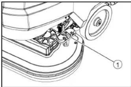
3. Pull the first disc brush sideways out from under the device head. 4. Hold the locking disc brush under the device head, press it upward and lock it. 5. Repeat the process for the second disc brush.
Troubleshooting
DANGER
Danger of injury! The device may start moving unexpectedly, posing a risk of injury.
Before carrying out any work on the device, set the lock switch to position "0" and remove the key. Remove the safety key from the device.
Dispose of the used brushes properly. In case of malfunctions that cannot be resolved with the help of this table, contact the service department.
Indicator lights
①Status indicator light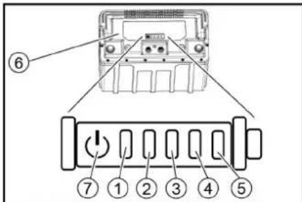
②Indicator light 1 ③Indicator light 2 ④Indicator light 3 ⑥Indicator light 4 ⑥ Battery ⑦Key
- Press the key and hold it for 5 seconds. The indicator light flashes: charge the battery. The status indicator light lights up green
Lights: all indicator lights together show the battery charge status.
The status indicator lights up with a red light: the light indicators indicate a malfunction. The malfunctions described in the following table can be fixed by the user. Report any malfunctions not described to the KARCHER service department.
Complies with the essential requirements of the EU Directives on safety and health protection. In the event of any modifications to the machine not approved by our company, this declaration loses its validity. Product: Floor cleaning device Type: 1.127-xx, 1.515-xx
Applicable EU Directives 2006/42/EC (+2009/127/EC) 2014/30/EC 2014/53/EC (TCU)
Harmonized standards applied
EN 60335-1
EN 60335-2-72
EN 55012: 2007 + A1: 2009
EN 61000-6-2: 2005
EN 62233: 2008
TCU
EN 301 511 V12.5.1
EN 300 440 V2.1.1
EN 300 328 V2.2.2
EN 300 330 V2.1.1
National standards applied
Chairman of the Board of Management
Director Regulatory Affairs & Certification
Person responsible for document release:
S. Reiser
Alfred Karcher SE & Co. KG
Alfred-Karcher-Str. 28-40
71364 Winnenden (Germany)
Phone: +49 7195 14-0
Fax: +49 7195 14-2212
Winnenden, 01.02.2021
Table of contents
Chairman of the Board of Management
S. Reiser
Director Regulatory Affairs & Certification
Winnenden, 2021/02/01
Table of contents
General notes. 142
Function 142
Intended use. 142
Environmental protection 142
Accessories and spare parts. 142
Scope of delivery 142
www.kaercher.com/REACH
General notes
Replacing the disc brushes
Type: 1.127-xxx, 1.515-xxx
Applicable EU directives
2006/42/EC (+2009/127/EC)
2014/30/EU
2014/53/EU (TCU)
Applied harmonized standards
EN 60335-1
EN 60335-2-72
EN 55012: 2007 + A1: 2009
EN 61000-6-2: 2005
EN 62233: 2008
TCU
EN 301 511 V12.5.1
EN 300 440 V2.1.1
EN 300 328 V2.2.2
EN 300 330 V2.1.1
Chairman of the Board of Management
S. Reiser
Director Regulatory Affairs & Certification
Authorized representative for documentation:
S. Reiser
Alfred Kärcher SE & Co. KG
Alfred-Karcher-Str. 28 - 40
Winnenden, 2021/02/01
Table of contents
General instructions 151
Operation. 151
Intended use 151
Environmental protection. 151
Accessories and spare parts 151
Scope of delivery 151
Safety instructions 151
Device description 152
Assembly 153
Start-up 154
Operation 154
Transport 155
Storage 156
Relevant EU directives 2006/42/EC (+2009/127/EC)
2014/30/EU
2014/53/EU (TCU)
Recommended batteries
Type: 1.127-xxx, 1.515-xxx
2006/42/EC (+2009/127/EC)
2014/30/EU
2014/53/EU (TCU)
Chairman of the Board of Management
S. Reiser
Director Regulatory Affairs & Certification
Documentation administrator:
S. Reiser
Alfred Karcher SE & Co. KG
Alfred-Karcher-Str.28-40
71364 Winnenden (Germany)
Tel.: +49 7195 14-0
Tip: 1.127-xxx, 1.515-xxx
Relevant EU Directive
2006/42/EC (+2009/127/EC)
2014/30/EU
2014/53/EU (TCU)
Harmonized standards applied
EN 60335-1
EN 60335-2-72
EN 55012: 2007 + A1: 2009
EN 61000-6-2: 2005
EN 62233: 2008
TCU
EN 301 511 V12.5.1
EN 300 440 V2.1.1
EN 300 328 V2.2.2
EN 300 330 V2.1.1
National standards applied
Chairman of the Board of Management
S. Reiser
Director Regulatory Affairs & Certification
Responsible for documentation: S. Reiser
Alfred Karcher SE & Co. KG
Alfred-Karcher-Str. 28 - 40
71364 Winnenden (Germany)
Tel.: +49 7195 14-0
Fax: +49 7195 14-2212
Winnenden, 2021/02/01
Contents
General notes 178 Function 178 Intended use 178 Environmental protection. 178 Accessories and spare parts. 178 Scope of delivery 178 Safety instructions. 178 Description of the machine. 179 Assembly 180 Commissioning 181 Operation. 181 Transport 183 Storage 183 Care and maintenance. 183 Troubleshooting. 184 Warranty. 185 Accessories for variant BD. 186 Technical data 186 EU declaration of conformity 186
General notes
Before using the device for the first time, read this original operating manual and the enclosed safety instructions. Follow the information and instructions contained therein.
Keep both documents for later use or for the next owner.
Function
2006/42/EC (+2009/127/EC)
2014/30/EU
2014/53/EU (TCU)
Applied harmonized standards
EN 60335-1
EN 60335-2-72
EN 55012: 2007 + A1: 2009
EN 61000-6-2: 2005
EN 62233: 2008
TCU
EN 301 511 V12.5.1
EN 300 440 V2.1.1
EN 300 328 V2.2.2
EN 300 330 V2.1.1
Chairman of the Board of Management
S. Reiser
Director Regulatory Affairs & Certification
71364 Winnenden (Germany)
Tel.: +49 7195 14-0
Fax: +49 7195 14-2212
Winnenden, 01.02.2021
Contents
General notes 187
Function 187
Type: 1.127-xxx, 1.515-xxx
Relevant EU directives
2006/42/EZ (+2009/127/EZ)
2014/30/EU
2014/53/EU (TCU)
Applied harmonized standards
EN 60335-1
EN 60335-2-72
EN 55012: 2007 + A1: 2009
EN 61000-6-2: 2005
EN 62233: 2008
TCU
EN 301 511 V12.5.1
EN 300 440 V2.1.1
EN 300 328 V2.2.2
EN 300 330 V2.1.1
Applied national standards
Chairman of the Board of Management
S. Reiser Director Regulatory Affairs & Certification
find at: www.kaercher.com/REACH
Accessories and spare parts
Use only original accessories and original spare parts, as they guarantee safe and trouble-free operation of the device. Information on accessories and spare parts can be found at www.kaercher.com.
Scope of delivery
Chairman of the Board of Management
S. Reiser
Director Regulatory Affairs & Certification
Person authorized for documentation:
S. Reiser
Alfred Karcher SE & Co. KG
Alfred-Karcher-Str. 28 - 40
71364 Winnenden (Germany)
Tel.: +49 7195 14-0
Winnenden, 2021/02/01
Designation 205
Function 205
Intended use 205
Environmental protection 205
Accessories and spare parts 205
Scope of delivery 205
Safety instructions 205
Troubleshooting 206
MoHTax 207
Pyskahe B eKcnIpoatauia 208
Ekcnnoataua 209
TpaHcnpTupaHe 210
Cbxpahene 210
Pnka n npdprkka 211
Pomou npn nobpeyn 212
TapaHcIy 213
PpHaJnEJXHOCTN BapnAHT BD. 213
TexHHueckn daHHN 214
Deklapaun 3a CbOTBETCTBNE Ha EC 214
06uynyka3aHn
Ppei nIpbBTOu3nOJI3BaHe Ha ypea npoUeTeToBa
opnHnHaHNO pKOBODCTBO 3a ekCnIooTaunu npNIOKeHnte yKa3aHna 3a 6e3oNaCHOCT. PpoueDnpaTe CbOTBEHO.
3ana3e Te DBeTe KnKKn 3a nocneBaUo n3non3BaHe NIn 3a CneBauuNcO6CTBEHnK.
The machine is designed for wet cleaning of flat surfaces.
By adjusting the amount of water or cleaning agent, the device can be adapted to the corresponding cleaning task. Cleaning agent or cleaning agent is added to the reservoir. The working width and the capacity of the reservoir for clean and dirty water (see chapter "Technical data") allow effective cleaning at high productivity of use. The device has a water stop.
Note
Depending on the cleaning task, the device can be equipped with different accessories. Please refer to our catalog or visit us on the Internet at www.kaercher.com.
Intended use
This device is suitable for professional and industrial use, e.g. in hotels, schools, hospitals, factories, shops, offices and rental objects. Use this device only in accordance with the instructions given in this operating manual.
- The device must only be used for cleaning surfaces that are insensitive to moisture or for polishing smooth floors.
- The device is not suitable for cleaning contaminated floors (e.g. in sanitary facilities).
- The device is not suitable for use in potentially explosive atmospheres.
- The device is approved for operation on surfaces with a maximum incline (see chapter Technical data).
Environmental protection
Packaging materials can be recycled. Please dispose of packaging in an environmentally friendly manner.
Worn electrical devices are subject to separate collection and must not be disposed of with household waste. At the end of its service life, dispose of the device properly. The device contains recyclable materials that should be recycled. Do not dispose of the device in household waste. For proper disposal, please contact your local waste disposal service or your KÄRCHER dealer.
Information on ingredients (REACH)
Current information on ingredients can be found at: www.kaercher.com/REACH
Accessories and spare parts
Only use original accessories and original spare parts. They ensure that the appliance is safe and trouble-free. Information on accessories and spare parts can be found at: www.kaercher.com.
Scope of delivery
Check the contents for completeness when unpacking. In case of transport damage or missing accessories, please contact your dealer.
Safety instructions
Before first use, read and follow these operating instructions and the enclosed safety brochure for high-pressure cleaners with spray guns, No. 5.956-251.0, and act accordingly. The device is approved for use on surfaces with limited slope (see Technical Data).
DANGER
Risk of tipping over!
The device can tip over on inclined surfaces. Do not work with the device on inclined surfaces. The device may only be used if the water tank cap is closed and the water tank is completely sealed.
Safety devices
DANGER
Do not bypass or modify safety devices!
The device is designed for your protection. Do not neglect, remove, or deactivate the protective devices.
Protective switch
The protective switch is activated exclusively.
Key switch
The key switch is activated with a key, and it is protected against unauthorized use.
Warning symbols
The battery charger is equipped with the following warning symbols:

Follow the instructions given in the battery charger's operating manual, as well as in this operating manual.
Protective goggles for the eyes.

Keep the battery away from acid.
Danger of explosion

Fire, sparks, open flames, and smoking are prohibited.
Danger of corrosion

Corrosive.

Warning instruction


He fills the battery in the container for waste.
Description of the device
Device parts
① Waste container (2) Brush for hoses (3) Float (4) Touch panel ⑤ Switch for the pump (6) Support bracket 7 Pressure switch ⑧ Cap of the reservoir for clean water ⑨ Support for the base
10 Reservoir for clean water (1) Battery (12) Filter for clean water 13 Mechanism of the reservoir for clean water (14) Disc brush 15 Reservoir for clean water 16 Pump cover 17 Hose for the brush
18 Opening for filling the clean water reservoir 19 Fastening tape 20 Adjustment of the height of the fastening tape ② Adjustment of the inclination of the fastening tape 2 Wing nut for fixing the fastening tape ② Brush holder
24 Indicator for the level of filling of the clean water reservoir 25 Discharge valve for clean water 26 Adjustable amount of water 27 Fastening tape 28 Battery 29 Switch 30 Speed control 31 Direction switch 32 Discharge valve for dirty water with dosing device
Battery
① Button ② Charge status indicator ③ Battery
Color marking
- The service elements for the cleaning process are marked. The service elements for maintenance and servicing are marked with light.
Symbols on the device

Discharge opening of the clean water reservoir

Discharge opening of the dirty water reservoir

Normal pressure of the head

Documentation

Pressure relief valve for clean water (50%)

Charging device connection

Fastening current

*Head cover

WARNING
Improper use for switching off
Danger of injury when switching off the charging device plug

Normal pressure of the head

Head cover

Pressure relief/venting of the head

Drain plug
- optional
Mounting
Unpacking
- Remove the cardboard packaging.
- Remove the adhesive tapes.
- Unscrew the fastening screws on the device and the delivery pipe. 4. Secure the hinges on the cardboard packaging and pull the device out of the packaging. Place the frame in front of the device and secure it with screws for the mounting plate.
①Mounting plate ②Delivery pipe ③Fastening screw
- Pull the delivery pipe, which is unpacked from the device, under the support frame and pull it out.
- Press the control head down and fix it in place.
- Only for BD 80/100 and BR 85/100: Press the control head down.
①Control head
Note
For BD 70/75 and BR 75/75 there is a control head. Releasing the control head is not necessary for this device. 8. Pull the device back out of the packaging. 9. Only for BD 80/100 and BR 85/100: Press the control head down.
Mounting the locking strap
- Place the locking strap in the locking strap guide.
- Tighten the clamping screws.
- Place the suction hose.
Battery replacement
| Уре́н Актулатор | |
| BD 70/75 W Classic Bp Pack 80 Ah Li | 1 x 6.654-454.0 |
| BD 70/75 W Classic Bp Pack 160 Ah Li | 2 x 6.654-454.0 |
| BD 80/100 W Classic Bp Pack 160 Ah Li | 2 x 6.654-454.0 |
WARNING
Danger of injury
Using other batteries may lead to injury. Use only the recommended batteries.
Installing and connecting the batteries
DANGER
Removing and installing the batteries
Unstable position of the machine. When removing and installing the batteries, ensure the machine is in a stable position.
WARNING
Replacing the fuse
Destructive electronics
When connecting the battery, ensure correct polarity.
WARNING
Charge the batteries before starting and during operation.
- Drain the water.
- Remove the reservoir for dirty water. 3. Remove the batteries.
- Place the batteries in the device as shown.
BD 80/100: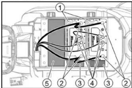
① Battery ② Battery pole ③ Seal 150x150x65 ④ Battery cover ⑤ Seal 90x185x335 (one on top of the other)
BD 70/75 80 Ah: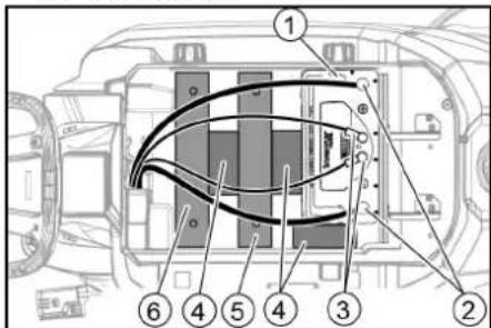
① Battery
② Battery pole ③ Battery cover ④ Seal 150x150x65 ⑤ Telescopic handle, 6 pieces ⑥ Telescopic handle, 14 pieces
BD 70/75 160 Ah: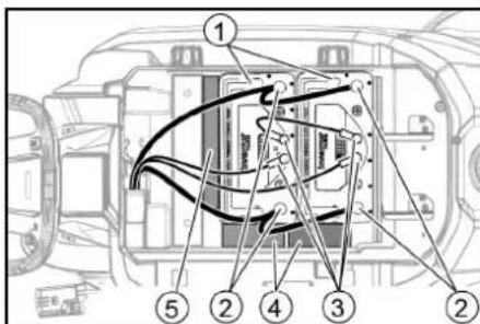
① Battery
② Battery pole ③ Battery cover ④ Seal 150x150x65 ⑤ Seal 155x300x60
- Place the seals and the telescopic handles as shown.
ATTENTION
Height adjustment
With the height adjuster, the position of the suction cups is adjusted in contact with the floor.
1. Move the device slightly forward. 2. Compare the position of the suction cups with the given figure.
①Spacer sleeve ②Base plate ③Screw
- Loosen the screw. 4. Between the suction cup and the spacer sleeve, place a shim to create the correct suction cup position.
- Place the remaining shims on the spacer sleeve.
- Tighten and secure the screw.
- Repeat the process for the second spacer sleeve.
- Move the device slightly forward.
- Check the position of the suction cups according to the floor. 10. If necessary, repeat the adjustment process.
Operation
Turning on the device
- Set the key switch to "1". The display shows sequentially: - until the next service, the software version, the service element, the battery charge status, and the number of operating hours
Operation
Indication
The float switch can be adjusted in time to change the level.
Through repeated turning clockwise and counterclockwise, the selected level can be adjusted more intensively.
- Set the switch for the movement direction to "Forward".
Operation
Note
The inclination and height of the measuring blades can be adjusted with the adjustment screw on the measuring result.
measuring (see chapter "Adjusting the measuring blades").
Note
If the reservoir for the dirty water is empty, the float switch closes the shut-off valve and the shut-off turbine works at reduced speed. In such a case, the measuring blades are lowered and you approach for emptying the dirty water reservoir.
- Turn the rotary switch for the working speed to the set value. During adjustment, the speed is shown on the display. The display is in percent of the maximum speed.
- Adjust the amount of water via the regulating valve.
- Press the button for the measuring blades. The measuring blades are lowered. The measuring starts.
- Press the button for the lifting device head, release it and let it return upward. 5. The lifting device head starts and moves at the set speed.
Increasing the pressure on the brushes
- Release the lifting device head. 2. Press the lifting device head down and fix it in place.
Check for leaks
Checking the connection
- Release the pressure relief valve.
- Press the start button and fill the tank to the top and secure it.
- Move the machine a short distance. The remaining water is drained. 4. Insert the drain hose. Drain the water periodically.
- Set the pressure relief valve to "0".
- If necessary, charge the battery.
Draining the dirty water
WARNING
Environmental hazard!
Environmental hazard due to improper disposal of waste water. Follow local regulations for waste water treatment. 1. Remove the drain hose and attach a suitable collection device.
- Press the drain hose down.
- Open the cap of the drain hose. 4. Drain the dirty water. Adjust the amount and the water flow through the nozzle. 5. Rinse the dirty water tank with clean water.
Draining the clean water
- Remove the cap of the indicator for the water level and close it after filling.
- Release the locking mechanism of the clean water reservoir.
- Leave the clean water to drain.
- Install and tighten the locking mechanism of the clean water reservoir.
Note: Stop tightening the screw for the mark in the locking mechanism of the clean water reservoir at the lowest point.
Transport
DANGER
Tilting hazard
Risk of tipping over when lifting and lowering the device. Tilt to the maximum value (see chapter "Technical data").
Move carefully.
WARNING
Unsecured load
Risk of tipping and injury during transport. Secure the load of the device.
Move the device with the help of another person or use a lifting device.
- Press the release button and lower the handle slowly.
- Before starting work, disconnect the device.
- Place the key switch in position "1". 4. Choose the direction. The movement direction is indicated by the arrow. 5. Press the brake pedal. 6. When transporting the device, use the lifting equipment and follow the instructions.
7. First place the device under the water reservoir.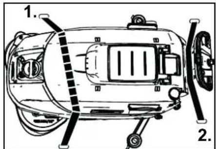
Storage
DANGER
Risk of injury and burns!
On inclined surfaces, the device may tip over. When storing, pay attention to the device's stability.
WARNING
Charging
Damage to the device from charging water or other liquids entering the device. Store the device in a place where charging conditions are met. This device must be stored only indoors. - For prolonged storage: 1. Charge the battery(ies) to between 30% and 50%. 2. Disconnect the charging device from the battery. 3. Press the button on the battery for 20 seconds to put the battery into sleep mode.
① Button
② Charge status indicator
③ Battery
The charge status indicator lights up briefly when the button is pressed. The charge status indicator does not respond when the button is pressed briefly.
Note
If you use the device with a battery, the process must be performed on only one battery. The remaining batteries automatically enter rest mode.
Maintenance and care
DANGER
Danger of injury!
The device must be switched off immediately if injury occurs.
Before any work on the device, set the key switch to "0" and lock the key.
Remove the mains plug from the charging device.
- Empty and rinse the tank and the water tank.
Safety inspection / maintenance contract
With your distributor you can agree on a regular safety inspection or conclude a maintenance contract. Please contact them.
Care after each use
ATTENTION
Incorrect cleaning
Risk of damage. Do not spray the device with water. Do not use aggressive cleaning agents. For a detailed description of the individual care tasks, see the chapter Care. - Empty the water tank. - Rinse the detergent tank with clean water. - Fill the device's detergent supply with clean water and run the pump briefly. - Check the coarse filter and clean it if necessary. - Clean the fine filter. - Clean the suction nozzles, check for wear, and adjust the height or replace them if necessary. - Check the disc brushes for wear and replace them if necessary. Charge the battery.
- If the charge level is below 50%, charge the battery without interruption. If the charge level is 50% or higher, charge the battery only if this is necessary to ensure sufficient operating time for the next use.
Instructions for the individual maintenance operations. In the chapter "Maintenance operations".
1. Drain the clean water reservoir and remove the deposits. 2. Clean the water filter. 3. Clean the float and the valve. 4. Check the battery terminals for oxidation, and if necessary clean them with a brush. Be careful with the
fixed wiring and the connected cables. 5. Clean the seal between the clean water reservoir and the channel, and check the tightness, and if necessary replace it. 6. Before putting the device back into operation, prepare it with a fully charged battery. At least once a month, charge the battery fully.
Annually
Perform the prescribed service inspection.
Maintenance operations
Replacing the suction lips
If the suction lips are worn down to the wear mark, they must be replaced.
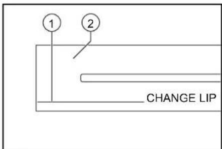
① Wear mark (2) Suction lip 1. Remove the suction tape. 2. Unscrew the star-shaped handles.
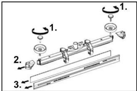
3. Remove the plastic parts. 4. Remove the suction lips. 5. Place the new suction lips. 6. Place the plastic parts. 7. Screw on and tighten the star-shaped handles.
Cleaning the coarse dirt filter
- Open the valve of the clean water reservoir.
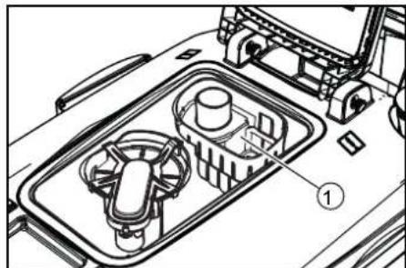
① Coarse dirt filter
2. Remove the coarse dirt filter upwards. 3. Rinse the coarse dirt filter under running water. 4. Place the coarse dirt filter back into the clean water reservoir.
Drain the water filter.
- Drain the clean water (see chapter Draining clean water).
- Unscrew the cap of the clean water reservoir.
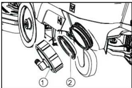
① Cap of the clean water reservoir ② Clean water filter 3. Remove the filter and rinse it with clean water. 4. Install the clean water filter. 5. Screw the cap of the clean water reservoir.
Note: Follow the instructions for tightening the cap of the clean water reservoir to the lowest point.
Cleaning the float and the brush seal
- Open the cap of the dirty water reservoir.
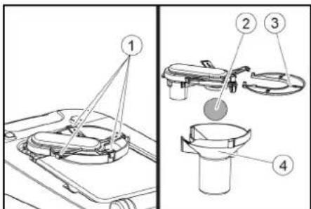
1. Locking device (2) Float ③ Brush seal ④ Float housing 2. Release the locking device.
3. Remove the float housing cover. 4. Remove the float from the housing and clean it. 5. Remove the brush seal and clean it. 6. Reassemble all parts in reverse order.
Replacing the disc brushes
1. Tilt the appliance head. 2. Press the brush replacement pedal downwards, overcoming the resistance.
① Brush replacement pedal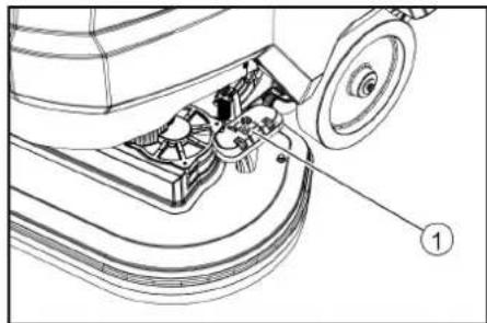
3. Remove the first disc brush from the underside of the appliance head. 4. Attach the new disc brush to the underside of the appliance head, press it upwards and secure it. 5. Repeat the process for the second disc brush.
Help in case of malfunction
△DANGER
Warning about handling!
It is necessary to ensure that the device is not damaged and to follow the instructions.
Before any work, set the ON/OFF switch to "0" and remove the plug. Then wait for the device to cool down.
- Remove the brush and the filter. - If the damage cannot be repaired with the help of the table, contact service.
Battery charge indicator
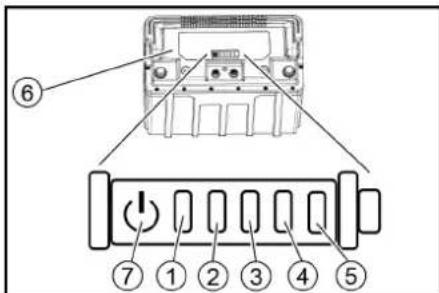
② Battery charge indicator 1 (3) Battery charge indicator 2 ④ Battery charge indicator 3 ⑤ Battery charge indicator 4 ⑥ Battery ⑦ Button
- Press the button for 5 seconds. The battery charge indicator lights up. The charge indicator lights up in green: the battery is charged.
The indicator shows the charge status of the battery.
The status LED lights up red: The indicator shows a fault. Describe the fault in the table. Some faults can be fixed by the user. For any faults not described, inform KARCHER service.
① Status LED
Functional variants
| Оьз nauseю BD 70/75 | ч act № | BD 80/100 ч act № | Описане |
| Ди SCOBа чЕТka, бяла (MHOrO мeкa) | 4.905-011.0 | 4905-030,0 | За поочтване на лесу заимberсени ялу чьвостваши подове |
| Ди SCOBа чЕТka, сесятваши влakнa (мeкa) | 4905-012,0 | 4905-031,0 | От сесятваши влakнa за поочтваши и поларанe |
| Ди SCOBа чЕТka, черваши (сpeдиha, стандарт ha) | 4905-010,0 | 4 905-000.0 | За уnotреба при BCЯКВИ стандартни.Deйноctи по поочтваши |
| Ди SCOBa чЕТka, черна (ТВьрда) | 4905-013,0 | 4905-032,0 | За сини замberсаяхи и за осовно поочтваши, сamo за нечьстelveни Hab'tиkni |
| Вьзбждаш дисс c положka | 4762-590,0 | 4762-447,0 | За поочтваши с положки, с поспособлиения за sbрза смаши Centerlock (цentралино заклочваши) |
| Оьз国家战略 BD 70/75 | ч act № | BD 80/100 ч act № | Описné |
| Подножka, бая | - | 6371-331,0 | За полигале на пове |
| Подножka, черва (средно мека) | 6369-003,0 | 6371-147,0 | За почиствае на всякakви пове |
| Подножka, зелега (средно Твърда) | 6369-002,0 | 6371-148,0 | За почиствае на силино замърсану пове и за осовно почиствае |
| Подножka, черна (Тьърда) | 6369-001,0 | 6371-169,0 | При улорити замърсану и за осовно почиствае |
| Подножka, кабява (SPP) | 2639-290,0 | 2639-288,0 | За задраваяне на повьржаши сюй на Тьърди и有很大очи повьрхости |
Technical data
| BD 70/75 W Class ic Bp | BD 80/100 W Class ic Bp | ||
| Данни за мошиноста на урEDA | |||
| Номинално напөгэнne | V | 2 | 4 |
| Каразитет на akумлатора | Ah (5 h) | 80 / 160 | |
| Средаю консуmpраю мошност | W 1270 | 1320 | |
| Мошноct на Тяговая дыгател | W 250 | 300 | |
| Мошноct на смугкATEЛната түбүнэ | W 500 | 500 | |
| Мошноct на задвожданeto на четкITE | W | 2 x 500 | 2 x 500 |
| Teоретчна мошноct на щеница плоч | m2/h | 3500 | 4000 |
| Обem на рeshерваора за чinctа вoda | I | 75 | 100 |
| Оьем на рeshерваора за мрьсан вoda | I | 75 | 100 |
| Temпэратура на вodату макс. | °C | 50 | 50 |
| Нajягане на вodату макс. | bar | 0,06 | 0,06 |
| Радиус на задвashes | mm | 1550 | 1650 |
| Нakлон на рashOTната зона, макс. | % | 2 | 2 |
| Измуквае | |||
| СмугкATEндаю мошноct, КOLINЧECTВО на Вьздуна | I/s | 24 | 24 |
| СмугкATEндаю мошноct, В��ум | kPa (mbar) | 16 (160) | 16 (160) |
| Почистваши четки | |||
| РавOTнши ршина | mm | 700 | 800 |
| Диамetedр на четкиte | mm | 356 | 410 |
| Овороти на четкиte | 1/min | 140 | 140 |
| BD 70/75 W Class ic Bp | BD 80/ 100 W Class ic Bp | ||
| Hалгане на при[tиckане на чetк'te 4 | 300 / 500 | 400 / 680 | |
| Размени в тergа | |||
| ДόнUCTIMо ob移到 тergо | kg | 325 | 435 |
| Собъединaco тergо (Tранспорно тergо) | kg | 251 | 325 |
| Рazмени otделенeto 3a akу[matopri] | mm | 575 x 380 | 622 x 384 |
| Установени STОйhoe TN CSыгласно EN 60335-2-72 | |||
| О[ba м StOйhoe Na m/s2<2,5 Вибрацята | m/s2<2,5 | ||
| HeystochyновocT K | dB(A) | 0,2 | 0,2 |
| Ниво на 3Букobо налягане LpA | dB(A) | 65 | 65 |
| HeystochyновocT КрA | dB(A) | 2 | 2 |
| Ниво на 3Букobа moшноct LWA + HeystochyновocT K WA | dB(A) | 81 | 81 |
| Заразьаме си праBOTо Na Текни: пожима. 3a СъOTBEТСВИЕ Na EC | |||
| СнacstотящоTo Deklapираме, чe посоченota ПО-ДОЛу Maшина NO CSOBЯ Концелочи И КОнсtrypкция, кAKTO И В пуното OT Hac Na пазара ИЗпьлесни. CSOTBECTBA Na ри�ложимITE OCHOВHI ИзickBaHA Na 3a Be3OПаСНоCT И Ona3Ване Ha 3dparBETO, onpeDEleneni B ДИректВИte Ha EC. Рпн Heьл气acyba Na сacпромяпа Ha Maшинata Ta3N Deklapaurigryu СВОТАВALINDHOC.T. Прodiaут: Урета поисвае На подove Туп: 1.127-xxx, 1.515-xxx | |||
| Пуложими ДИректВИ Na EC 2006/42/EO (+2009/127/EO) 2014/30/EC 2014/53/EC (TCU) Пуложими Харmonи: STANДAPТN EN 60335-1 EN 60335-2-72 | |||
EN 55012: 2007 + A1: 2009
EN 61000-6-2: 2005
EN 62233: 2008
TCU
EN 301 511 V12.5.1
EN 300 440 V2.1.1
EN 300 328 V2.2.2
EN 300 330 V2.1.1
The above standards
The declaration is issued under the sole responsibility of the manufacturer.
H. Jenner
Chairman of the Board of Management
S. Reiser
Director Regulatory Affairs & Certification
71364 Winnenden (Germany)
Tel.: +49 7195 14-0
Fax: +49 7195 14-2212
Winnenden, 2021/02/01
Table of Contents
General instructions 215
Function 215
Intended use 215
Environmental protection 215
Mounting the suction hose
- Place the suction hose in the hanging bracket.
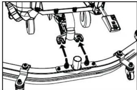
- Tighten the wing nuts.
- Connect the suction hose.
Batteries
Recommended batteries
| Seade Aku | |
| BD 70/75 W Classic Bp Pack 80 Ah Li | 1 x 6.654-454.0 |
| BD 70/75 W Classic Bp Pack 160 Ah Li | 2 x 6.654-454.0 |
| BD 80/100 W Classic Bp Pack 160 Ah Li | 2 x 6.654-454.0 |
CAUTION
Risk of damage
Type: 1.127-xxx, 1.515-xxx
H.Jenner Chairman of the Board of Management
S. Reiser Director Regulatory Affairs & Certification
Documentation officer:
S. Reiser
Alfred Karcher SE & Co. KG
Alfred-Karcher-Str.28-40
71364 Winnenden (Germany)
Tel: +49 7195 14-0
Winnenden, 2021/02/01
Contents
General notes 224 Operating principle. 224 Intended use 224 Environmental protection. 224 Accessories and spare parts 224 Scope of delivery 224 Safety notes 224 Description of the device 225 Assembly 226 Commissioning 227 Operation. 227 Transport 229 Storage 229 Care and maintenance. 229 Troubleshooting 230 Warranty 231 Additional equipment for BD variant. 232 Technical data 232 EU declaration of conformity. 232
General notes
Before using the device, read these original operating instructions.
Type: 1.127-xxx, 1.515-xxx
H.Jenner Chairman of the Board of Management
S. Reiser Director Regulatory Affairs & Certification
Documentation prepared by: S. Reiser
Alfred Karcher SE & Co. KG
Alfred-Karcher-Str.28-40
71364 Winnenden (Germany)
Tel.: +49 7195 14-0
Fax: +49 7195 14-2212
Winnenden, 01.02.2021.
Table of contents
| BD 70/75 W Classic Bp Pack 80 Ah Li | 1 × 6.654...454,0 |
| BD 70/75 W Classic Bp Pack 160 Ah Li | 2 × 6.654...454,0 |
| BD 80/100 W Classic Bp Pack 160 Ah Li | 2 × 6.654...454,0 |
DÉMESIO
Risk of slipping
Type: 1.127-xxx, 1.515-xxx
Applicable EU directives
2006/42/EC (+2009/127/EC)
2014/30/EU
2014/53/EU (TCU)
Applicable harmonized standards
EN 60335-1
EN 60335-2-72
EN 55012: 2007 + A1: 2009
EN 61000-6-2: 2005
EN 62233: 2008
TCU
EN 301 511 V12.5.1
EN 300 440 V2.1.1
EN 300 328 V2.2.2
EN 300 330 V2.1.1
Applicable national standards
The undersigned persons act under the authorization of the company's management.
H.Jenner
Chairman of the Board of Management
Director Regulatory Affairs & Certification
Read the original instructions for use and safety instructions before using the device. Follow them accordingly.
Keep the operating instructions for future reference.
Use the device only as intended.
Function
The device is intended for cleaning hard surfaces. Depending on the amount of dirt, the device can be used for various tasks. The amount of cleaning agent is regulated by its dosage.
The working width and capacity of the brushes ensure effective cleaning during use (see chapter "Technical data").
The device is equipped with a brush.
Accessories
Depending on the task, the device can be equipped with different accessories. Order them from the catalog or find them on the internet at www.kaercher.com.
Intended use
This device is intended for commercial and industrial use, for example in hotels, schools, workshops, parks, shops, offices, and similar premises. Use this device only in accordance with the instructions in the operating manual.
- The device can be used for cleaning water-resistant surfaces that are suitable for wet cleaning.
- The device is not suitable for cleaning frozen bottles (e.g., in cold storage).
- The device is not suitable for use in an explosive environment. Use it only on surfaces with a maximum incline (see chapter Technical specifications).
Environmental protection
Packaging materials are recyclable. Please dispose of packaging in an environmentally responsible manner.
Electrical and electronic devices contain valuable materials that are recyclable and components such as batteries, accumulators, or oil that, if improperly handled or disposed of, can pose a potential hazard to health and the environment. However, these components are necessary for the reliable operation of the device. Devices marked with this symbol must not be disposed of with household waste.
Information on components (REACH)
Current information on components is available at: www.kaercher.com/REACH
Accessories and spare parts
Only use original accessories and original spare parts, as they ensure safe and trouble-free operation of the device. Information on accessories and spare parts is available at www.kaercher.com.
Scope of delivery
Check the completeness of the device when unpacking. In case of missing accessories or damage during transport, please contact your dealer.
Safety instructions
Before first use, read the operating instructions and the brochure, and follow the safety instructions when working with handheld and mobile devices and handheld and mobile device accessories (EN 60335-2-1) and comply with them.
The device may only be used on surfaces with a maximum incline (see chapter Technical specifications).
Safety instructions!
The device may tip over on inclined surfaces.
It is forbidden to operate the device on inclined surfaces. The device may only be operated when all covers and guards are closed.
Safety devices
DANGER
Missing or modified safety devices!
Safety devices are intended for your protection.
Do not ignore, remove, or deactivate safety devices.
Safety switch
In the event of an emergency stop, the device stops.
Locking switch
In the event of a malfunction, the device is locked against unauthorized use.
Warning symbol
Operator's manual

Press the head of the adjusting screw

Spare parts
Description
Installation
In the package
- Remove the cardboard box.
- Remove the shrink film. 3. Open the front covers, secured with screws on the bottom.
- Using the top cover of the cardboard packaging as a fixation tab, attached across the pallet, before installation, install and close the curtains.
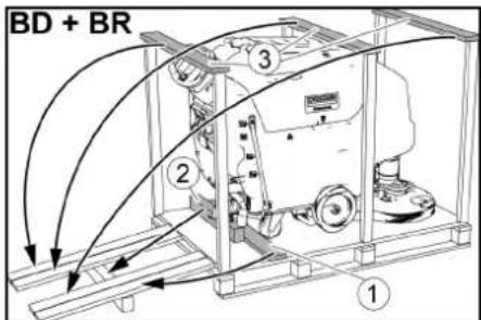
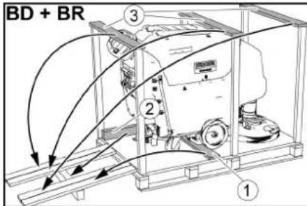
①Fixation tab ②Wooden beam. ③Cover hinge
- Insert the wooden beam, released from the pallet, into the frame of the installation and bend it.
- Press the adjusting screw head down and lock it in place.
- Only for BD 80/100 and BR 85/100: Press the lever down.
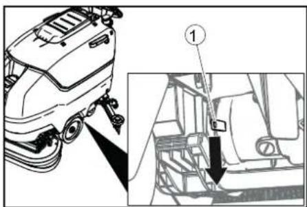
Lever
Indicator
YBD70/51BR75/52a lever mechanism. In this device, the lever is loosened and needs adjustment.
- Ctrnhytn npncptpi 3aD0m 3 nioHa.
- TINbKn DnB BD 80/100 i BR 85/100: BiTnCHyTN BBepx Baxin b ranbMa.
BcTaHOBJIeHHB CMOKTyBaIbHoi INaHKn
- BCTaBHTN BCMOKTyBaIbHy nJaHky B nDicky BCMOKTyBaIbHoI nnHaHKn.
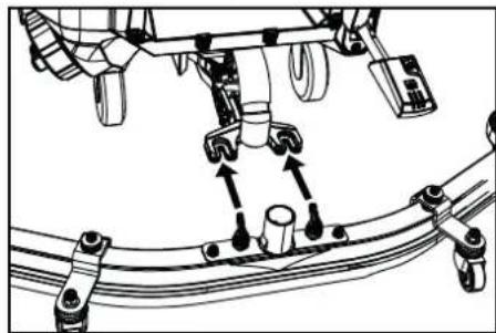
2.3aTn CMyuKOBi rAn. 3. HadaTn yCMOKTyBaIbHn IJIaHI.
AkymnyTopn
PekomeHdoBani akymyIaTopi
| Пристрий Актуларов | |
| BD 70/75 Вт Classic Bp Pack 80 A rod Li | 1 x 6.654-454.0 |
| BD 70/75 Вт Classic Bp Pack 160 A rod Li | 2 x 6.654-454.0 |
| BD 80/100 Вт Classic Bp Pack 160 A rod Li | 2 x 6.654-454.0 |
YBAGA
He6e3neKa nowkodxeHHa
BukopucmaHH iHux akymynamopie MOKe nowkodmu npucmpi. Bukopucmoeyamu nuwe pekomehdoa hi akymyarnopu.
YctahOBnEHn i nikNoeHHn akymyIaTOPiB
△OBEPEXHO
Demohmaxi ecmahoeHnHa kymynapoie
Hecmiuke nooxkeHHaMuuHu Pid yac demohmaxy i ecmahoeeneHH akyMylamopie nepekoHamuc e cmiKomy nonoKeHHi MaunuHu.
YBACA
Connect the battery charger to the battery, observing the correct polarity.
WARNING
Deep discharge
Risk of damage before commissioning. Charge the battery.
- 1. Fill with distilled water. 2. Check the acid level.
- Disconnect the battery charger.
- Insert the battery into the device as shown in the figure.
BD 80/100: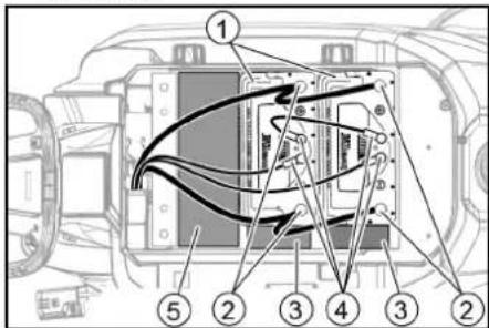
①Battery ②Battery compartment ③Recess 150x150x65 ④Round connector ⑤Recess 90x185x335 (2 pcs. one above the other)
BD 70/75 80 A year: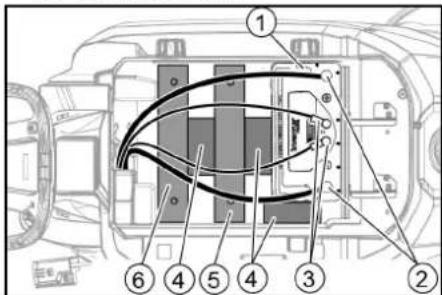
①Battery
②Battery compartment ③Round connector ④Recess 150x150x65 ⑤Additional weight, 6 plates ⑥Additional weight, 14 plates
BD 70/75 160 A year: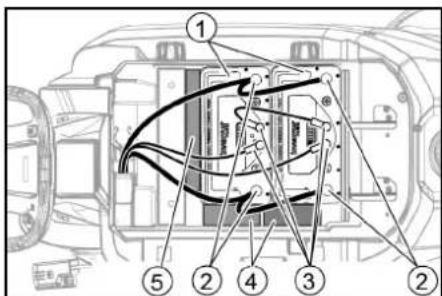
①Battery ②Battery compartment ③Round connector ④Recess 150x150x65 ⑤Recess 155x300x60
5. Connect the sprayer and additional tanks as indicated.
Instruction
Danger of damage
If the polarity (positive and negative terminals) is reversed, it will lead to damage of the electronic control unit. Connect the red cable to the positive terminal and the black cable to the negative terminal. When connecting, follow the above instructions. 6. Connect the charging cable to the battery terminals (+) and (-).
The device cannot be used during charging.
Instruction
The device is equipped with protection against deep discharge, so if the minimum capacity value is reached, the device and the turbine are switched off.
- Connect the device directly to the charging device, avoiding contact with surfaces.
- Disconnect the battery from the device side.
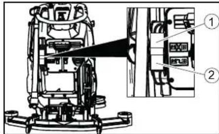
- Fill the tank with clean water.
Instruction: The drain valve can be used to empty the tank. The scale is marked on its inner side.
Adjusting the amount of water
- Adjust the amount of water on the regulator depending on the contamination of the surface to be cleaned.
Instruction
First attempts at cleaning should be done with a small amount of water. Gradually increase the amount of water until the desired result is achieved.
For the water tank for clean water, the shut-off unit must be installed without water supply.
Installation of the shut-off plate
Adjusting the pressure
The pressure must be adjusted so that the shut-off edges of the shut-off plate are evenly pressed against the floor along the entire length.
- Loosen the screw.
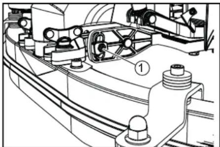
Screw
- Adjust the pressure of the shut-off plate.
- Then tighten the screw.
Adjusting the height
Adjusting the height affects the shut-off edges' contact with the floor.
- Move the device slightly forward.
- Compare the height of the shut-off edges with the figure below.
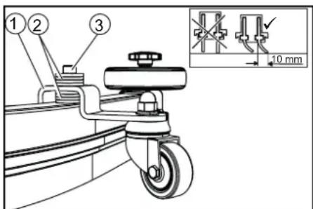
1. Distance spacer 2. Underlay plate 3. Turn the screw.
4. Set the required number of gaps between the shut-off plate and the distance roller to form the correct height of the shut-off edge. 5. Place the washer on the surface of the distance roller. 6. Turn and tighten the screw. 7. Repeat the procedure for the other distance roller. 8. Move the device slightly forward. 9. Check once more the height of the shut-off edges along the entire length. 10. If necessary, repeat the adjustment.
Device operation
1. Set the lock switch to the «1» position.
The display sequentially shows the following:
- Time until next maintenance; software version, control unit; battery charge level and number of operating hours.
Movement
Indicator
The direction of movement can be changed during cleaning. Thanks to this, it is possible to clean one area by moving the device forward and backward.
- Set the movement switch to the «Forward» position.
Cleaning
Indicator
To increase the efficiency of the vacuum cleaner, you can adjust the height and width of the vacuum bar (see section Setting the vacuum bar).
Indicator
If the tank is full of dirty water, the float closes the opening for vacuuming, and the vacuum turbine operates with reduced power. In this case, lower the vacuum bar and move the device to empty the tank for dirty water.
1. Set the detergent flow rate to the required value. During adjustment, the flow rate is displayed on the display. The value is displayed as a percentage of the maximum flow rate. 2. Adjust the number of revolutions of the brush. 3. Press the vacuum bar lowering button. The vacuum bar lowers. The vacuuming process begins. 4. Press the cleaning head lowering button, spread and release.
- Insert the plug into the socket. The flushing head is activated, and the device moves with the set speed.
Increase the flushing speed.
- Release the plug. 2. Press the flushing head and lock it in place.
Confirm the flush.
Confirmed flush.
- Release the plug.
- Press the flushing head down and lock it in place. 3. Move the lever to the short distance. The water supply is connected. 4. Lift the lever to the flushing position. The flushing process takes about 10 seconds. 5. Set the switch to position «0».
- If necessary, charge the battery.
Draining the water.
WARNING
Water drainage is blocked!
Water drainage is blocked due to improper use of the drain. Follow the local rules for handling waste water. 1. Remove the plug from the drain and place it in the designated container for water.
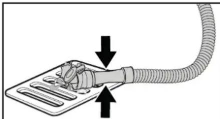
2. Lower or tilt. 3. Open the cover of the flushing device. 4. Drain the water. Adjust the amount of water for flushing or tilting. 5. Rinse the drain with clean water.
Draining clean water.
- Remove the plug, lower the lever, and flush the drain.
- Bleeding the fuel system and the injection pump.
- 3. Then tighten the drain plug of the fuel filter housing.
Note: make sure that the fuel return pipe from the injection pump is at the lowest point after tightening.
Transportation
DANGER
Moving parts
Danger of injury when operating or maintaining the device for loading and unloading only under supervision up to the maximum level (see section "Technical characteristics"). Keep hands away.
SURFACE
Hot surface
Danger of injury and damage
When transporting, observe the safety instructions for the device.
Operate the device only with the help of another person or with the help of a drive of the running part.
- Put on the protective helmet and fasten it correctly. 2. Check the device.
- Set the locking switch to position "1".
- Turn the direction of movement using the movement direction switch.
- Press the emergency stop button. 6. During transportation by vehicles, it is necessary to secure the device against shifting and overturning in accordance with applicable rules.
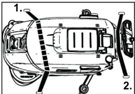
7. First, loosen the belt straps on the tank for the fuel tank.
Storage
SURFACE
Danger of tipping and falling!
The device may tip over on inclined surfaces.
When storing, take into account the weight of the device.
ATTENTION
Freezing
Damage to the device as a result of freezing of water.
Drain water from the device. Store the device in a place protected from frost.
- The device must be stored only in heated rooms. -Before long-term storage:
- Charge the battery(s) to a level from 30% to 50%.
- Disconnect the device from the mains plug.
- Press and hold the button on the battery for 20 seconds to switch the battery to sleep mode.
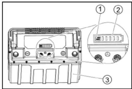
1Button ② Indicates charge status ③Battery
The charge status indicator lights up and goes out one by one. The charge status indicator no longer reacts to a short press.
Bka3ieKa
For devices with multiple batteries, this process should be performed on only one battery. The other batteries automatically switch to sleep mode.
Oorra TaTexHicHe 06cnyroByBaHHa
SAFETY
Safety instructions
The device may start unexpectedly and cause injury.
Before carrying out any work on the device, switch the main switch to the «0» position and remove the key.
Remove the battery from the device.
Clean with a dry and clean cloth and do not use water.
Safety check / Maintenance instructions
Before carrying out maintenance work, disconnect the appliance from the power supply. We recommend consulting a specialist.
Maintenance frequency
1. Coarse filter. 2. Remove the coarse filter and clean it. 3. Rinse the coarse filter under running water. 4. Insert the coarse filter back into the tank for clean water.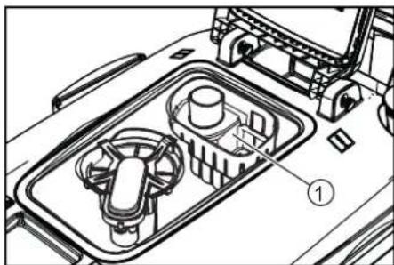
Cleaning the clean water filter
- Drain the water (see section 'Draining the clean water').
- Unscrew the lock of the clean water tank.
1. Lock of the clean water tank. 2. Clean water filter. 3. Remove the clean water filter and rinse it with clean water. 4. Insert the clean water filter. 5. Install the lock of the clean water tank.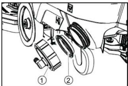
Note: Make sure that the pipe for connecting the hose to the clean water tank lock is at the bottom after installation.
Cleaning the nozzle and brush
Replacing the disc brushes
1. Tilt the cleaning head. 2. Press down the pedal for replacing the brushes, overcoming resistance.
1. Pedal for replacing the brushes. 3. Remove the first disc brush from under the cleaning head. 4. Place the new disc brush under the cleaning head, press it upward and lock it. 5. Repeat the process for the second disc brush.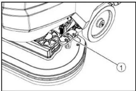
Troubleshooting
DANGER
Danger of injury!
Before using the device for the first time, read these instructions.
Before using the device, insert the battery into the device and charge it fully.
Remove the battery from the device before charging.
Remove the battery and dispose of it properly. - In case of malfunctions that cannot be eliminated with the help of this table, contact the service department.
Battery status indicator
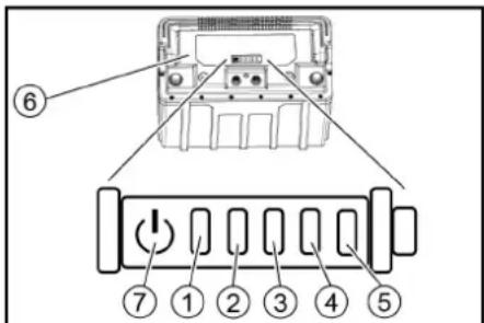
② Indicator light 1 ③ Indicator light 2 ④ Indicator light 3 ⑤ Indicator light 4
⑥Battery
⑦Button
- Press and hold the button for 5 seconds.
- When the indicator lights do not light up:
Charge the battery.
The status indicator lights up green: all indicator lights together indicate the battery charge level. The status indicator lights up red: the indicator lights indicate a malfunction. The malfunctions described in the following table can be eliminated by the user. Contact the KARCHER service department for any malfunctions not described.
(1)LED status
| (1) | (2) | (3) | (4) | (5) | Прочина | Усунения |
| червовский | - | - | - | - | Актуларов Занаду rapаян. | Дату akтуларов охолонут. |
| червовский | - | - | - | 3elenen | Состema керувань Akтуларов Наду harpinacb. | Дату akтуларов охолонут. |
| червовский | - | - | 3elenen | - | Актуларов Занадухолodни ду зарджанн. | ПеремICTИТу писстрий у тенише місяцу та посякати, ду осы Akтуларов не harpi'eТбя. |
| червовский | - | - | 3elenen | 3elenen | Занаду Висoke с鞘кованьсту'mу пid час зарджанн. | Витягуну StPenceьну Влику зристо 3 розетки. 3ачекати 10 сенид. 3нову Bставпіи StPenceьну Влику.Як soo HeapspavHic'tb 3'Явсятбя 3Нову,замінітБ зристо. |
| 3azenаду Висoke с鞘кованьсту'mу писстю. | Вимкугуну писстri.Як soo пису вимкунену HeapspavHic'tb Влинkae 3Нову,сдіd šукати HeapspavHic'tb у писто. | |||||
| червовский | - 3elenen | - | - 3elenen | - | Коротke зам kenань. | Перевироти bci πідк nullуенна Akтуларов. |
| червовский | - 3elenen | - | 3elenen | - | Наду Изьka的手рuya Akтуларовпинх сlementтір ріп розяджени. | ЗaporдUTи Akтуларов. |
| червовский | - 3elenen | - | 3elenen | 3elenen | Наду Висoke的手рuya Akтуларовпинх сlementтір пid час зарджанн. | Рozядіть Akтуларов до 20% залишкоові emhocti. Потім зaporдUTи Akтуларов. |
| червовский | 3elenen | - | - | 3elenen | Занаду Изьka的手рuya Akтуларов. | ЗaporдUTи Akтуларов. |
| червовский | 3elenen | - | 3elenen | - | popушени зардного писстю. | Витягуну StPenceьну Влику зристо 3 розетки. 3ачекати 10 сенид. 3нову Bставпіи StPenceьну Влику.Як soo HeapspavHic'tb 3'Явсять с佩пстір. |
| червовский | 3elenen | - | 3elenen | 3elenen | ||
| червовский | 3elenen | - | 3elenen | - | Актуларов Занадухолodни ду вдачіnotужноcti. | ПеремICTИТу писстriу у тенише місяцу та посякати, ду осы Akтуларов не harpi'eТбя. |
| червовский | 3elenen | - | 3elenen | - | Занадупхись писстю. | Вимкугуну писстri.Як soo HeapspavHic'tb 3беріра'tьсь, зberпільск do cebrісchio佟 сухжы. |
Malfunction without indication
| Hecnpabnictb | UcynenHn |
| Ппсстрии не залуckaстбя | 1. Встановпглзамковий вимькay в положення «1». 2. Розлесувати Кногу abapійногу Вимкинся на панелі керваши, поернувши II. (Примітka: не восты восты ріstwoь оснашени Кногкою abapійногу Вимкинся.) |
| 3. 3адіятызамковий вимькay. | |
| 4. Встановпakумлaitорништокр. | |
| 5. Перавирпглakулaitори, за необхідноcti зарядntи. | |
| 6. Перавирпngлікоченny полочи Вимьдів akumулaitopі. | |
| Кількість вodni недостастя | 1. Перавирпглпевь чістоі Bodи, за неobхідноcti заловпгпь�ябak. 2. 3більшити Кількість Bodи за діопомого ретулітopa Кількostі Bodи. 3. Oчістіпгліпгі рістоі Bodи. 4. Перавирпьшалги на пі overdmet засмічень, за неobхідноcti очістіп. |
| Hecnpabnictb Ucynenhh | |
| 3aHaJTo Hn3bKa NotyXhIcTb BCMOKTyBaHnh | 1. 3yInHHTn npinctpi i 3nHTn 6pydNv Bodv. 2. Ouchntn yuizIbHeHHm iKx 6akom dIy 6pydN0i Bodv i KpIshkoH o I nepeBipNTn Ha repMeTHnHCTb, 3a Heo6xIdnocti 3amHHTn. 3. IpeBepRITn npabInbHcTb 3'edHAnHcy BCMOKTyBaHbHOrO 7IpaHra 3 6akom dIy 6pydN0i Bodv. 4. IpeBepRITn BORCOBn φIbTp Ha 3a6pydNehn, 3a Heo6xIdnocti OChCTHn. 5. Ouchntn ycmoktyBaHbHi kpaIKn Ha BCMOKTyBaHbHi pIaHci, 3a Heo6xIdnocti nepeBepHytn a60 3aMHNt. 6. IpeBepRITn qy 3akrtna KpIshka Ha 3IINBHomU 7IpaHra 6pydN0i Bodv. 7. IpeBepRITn HalaHTyBaHn BCMOKTyBaHbHi pIaHci. 8. IpeBepRITn BCMOKTyBaHbHi shaHr Ha predmet 3acMueHnry, 3a Heo6xIdnocti OChCTHn. Pid qac NoBTOHO BCTAHOBLeHnry 7IpaHra 6Ia BIDMtKa Ha 7IpaHry NOBHNHs 3HaxOHTNCsHa 3aTnCKaHi. 9. IpeBepRITn BCMOKTyBaHbHi shaHr Ha rePmeTnCHCTb, 3a Heo6xIdnocti 3amHHTn. |
| Pe3yIbTat OunSeHnne He3aDoBilbHni | 1. 3Hn3HTn 7bVdKicTb. 2. IpeBepRITn 7itKn Ha 3HoWeHnry, 3a Heo6xIdnocti 3amHHTn. 3. IpeBepRITn TIN 7itOK Ta MInOch 3acIb Ha npDAtnHCTb. |
| YcmokTuBaJIbHa Tpy6Iha IpaIouc 3 niDnIeHnM UncIOM o6eTrib | 1. 3LHTn 6pydNv Bodv. 2. Ouchntn nonIaBeCb. 3. IpeBepRITn BORCOBn φIbTp, 3a Heo6xIdnocti OChCTHn. 4. IpeBepRITn BCMOKTyBaHbHi shaHr Ha predmet 3acMueHnry, 3a Heo6xIdnocti OChCTHn. 5. IpeBepRITn BCMOKTyBaHbHi pIaHcy Ha predmet 3acMueHnry, 3a Heo6xIdnocti OChCTHn. |
| UItkA He o6eTbcS | 1. IpeBepRITn qy He 3a6nOkobAha 7itKa cTOpOHm mpredmetom, 3a Heo6xIdnocti BVDaIHTn cTOpOHnII pIeDMet. |
| Iprnstri B6pye niz cac OunIeHnne | 1. BvKopnCTOBvBatn 6IbIbM'aykuy zltky. |
| CByIooIodn «AkyMylantop BvdKnIoueHn», 80% i 100% Ha 3apIyHmOp npIcTPOI 3aRopIyTOBcK kInbKa pa3IB ODIN 3a ODHm | 1. 3aRyIhN npinctpi y pfazI nepe3aIqdn. Ppi cybOMy BvIPBnOeTbcS CTan 3apIyD okpeMIX enemertlb AkyMylantop. HecnpaBnICTb npincytb IliE B TOMy Bvnapk, kIzIO cbTIOIod «AkyMylantop BvdKnIoueHn» noctIHO CBITNbCS. |
| AkyMylantop He 3apIyKAcTbcS | AkyMylantop rIi6oko po3prJdxeHn i He moke 6bytN 3anyIeHn 3apIyHm npinctpoeM. 1. PidKnIOuHTn 3apIyHn npinctpi do MepeKj ta akymylantop. 2. HatnschyTn y TpyMylBATn KhoKny Ha akymylantop i Dobwe 5 cekynd. Akymylantop 3anyckaεTbcS, i noUHnAeTbcS proocc 3apIyJxHn. |
Warranty
The warranty conditions established by the manufacturer's authorized organization for this product are valid in this country. Possible malfunctions during the warranty period are eliminated free of charge.
We eliminate defects free of charge if it is proven that the malfunction is caused by material defects or manufacturing defects. In case of a claim during the warranty period, please contact the seller or the nearest authorized service center with this device.
Please attach the purchase receipt or warranty card.
(Addresses see reverse)
Appendix to Warranty
Director Regulatory Affairs & Certification
Person responsible for documentation:
S. Reiser
Alfred Karcher SE & Co. KG
Alfred-Karcher-Str. 28 - 40
71364 Winnenden (Germany)
Tel.: +49 7195 14-0
Fax: +49 7195 14-2212
Winnenden, 01.02.2021

THANK YOU!

Register your product and benefit from many advantages.
www.kaercher.com/welcome


Rate your product and tell us your opinion.
www.kaercher.com/dealersearch
Alfred Kärcher SE & Co. KG
Alfred-Karcher-Str.28-40
71364 Winnenden (Germany)
Tel.: +49 7195 14-0
Fax: +49 7195 14-2212
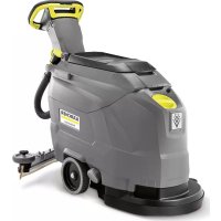
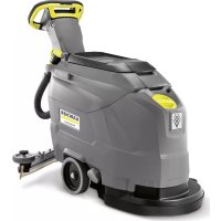
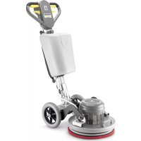
- CONTENTS
- GENERAL NOTES
- FUNCTION
- NOTE
- INTENDED USE
- ENVIRONMENTAL PROTECTION
- ACCESSORIES AND SPARE PARTS
- SCOPE OF DELIVERY
- SAFETY INSTRUCTIONS
- WARNING
- RISK OF INJURY
- SAFETY DEVICES
- CAUTION
- MISSING OR MODIFIED SAFETY DEVICES
- SAFETY SWITCH
- KEY-OPERATED SWITCH
- WARNING SYMBOLS
- DESCRIPTION OF THE UNIT
- OVERVIEW OF THE DEVICE
- BATTERY
- COLOUR CODING
- SYMBOLS ON THE DEVICE
- BRUSH REPLACEMENT PEDAL
- INSTALLATION
- UNLOADING
- INSTALLING THE SUCTION BAR
- BATTERIES
- RECOMMENDED BATTERIES
- ATTENTION
- RISK OF DAMAGE
- INSTALLING AND CONNECTING BATTERIES
- REMOVING AND INSTALLING THE BATTERIES
- INCORRECT CONNECTION POLARITY
- DEEP DISCHARGE
- BD
- BD 70/75 160 AH
- REMOVING THE BATTERIES
- INITIAL STARTUP
- CHARGING THE BATTERY
- DANGER
- USING AN UNSUITABLE CHARGER
- OPERATION
- RISKS DURING OPERATION
- FILLING WITH OPERATING MATERIALS
- FILLING FRESH WATER
- NOTES ON DETERGENTS
- RISK OF DAMAGE TO THE DEVICE
- DETERGENT
- ADJUSTING THE WATER VOLUME
- ADJUSTING THE SUCTION BAR
- ADJUSTING THE INCLINATION
- ADJUSTING THE HEIGHT
- CLEANING
- SWITCHING ON THE DEVICE
- DRIVING
- INCREASING THE BRUSH CONTACT PRESSURE
- FINISHING OPERATION
- FINISHING CLEANING
- DRAINING THE WASTE WATER
- ENVIRONMENTAL POLLUTION
- DRAINING FRESH WATER
- QUICKLY DRAINING FRESH WATER
- TRANSPORT
- DRIVING ON SLOPES
- FAILURE TO OBSERVE THE WEIGHT
- STORAGE
- FROST
- CARE AND MAINTENANCE
- △DANGER
- SAFETY INSPECTION/MAINTENANCE CONTRACT
- MAINTENANCE INTERVALS
- EACH TIME AFTER USE
- MONTHLY
- ANNUALLY
- MAINTENANCE WORK
- TURN OVER OR REPLACE THE WORN SUCTION LIPS
- CLEANING THE COARSE DIRT FILTER
- CLEANING THE FRESH WATER FILTER
- CLEAN THE FLOAT AND FLUFF FILTER
- REPLACING THE DISC BRUSHES
- TROUBLESHOOTING GUIDE
- BATTERY STATUS INDICATOR
- WARRANTY
- DECLARATION OF CONFORMITY
- EU DECLARATION OF CONFORMITY
- CURRENTLY APPLICABLE EU DIRECTIVES
- HARMONISED STANDARDS USED
- TCU
- NATIONAL STANDARDS USED
- DECLARATION OF CONFORMITY (UK)
- CURRENTLY APPLICABLE UK REGULATIONS
- DESIGNATED STANDARDS USED
- INDEX
- TABLE OF CONTENTS
- APPLICABLE EU DIRECTIVES
- INDICES
- DISASSEMBLE THE BATTERIES
- WRONG SLOT
- ASSEMBLY
- READING
- HAZARDOUS SITUATION DURING OPERATION
- USE OF HARMONIZED STANDARDS
- APPLIED NATIONAL STANDARDS
- HARMONIZED STANDARDS APPLIED
- NAYEROS
- YRRO8E1N
- ZNE YKA3AHN
- ФУНКЕЛЯ
- PPUMEYAHUE
- ICNOJB3OBAHNNE NHA3HAUEHNIO
- PROTECTIVE DEVICES CAUTION
- PROTECTIVE SWITCH
- LOCKING SWITCH
- DEVICE DESCRIPTION
- DEVICE OVERVIEW
- COLOR CODING
- UNPACKING
- INSTALLING THE SUCTION HOSE
- INSTALLING AND CONNECTING THE BATTERY PACKS
- DANGER OF DAMAGE
- COMMISSIONING
- CHARGING THE BATTERY. DANGER
- USE OF AN UNSUITABLE CHARGING DEVICE
- CLEANING THE CLEAN WATER FILTER
- CLEANING THE FLOAT AND THE FELT FILTER
- TROUBLESHOOTING
- INDICATOR LIGHTS
- RELEVANT EU DIRECTIVE
- NATIONAL STANDARDS APPLIED
- APPLIED HARMONIZED STANDARDS
- UYNYKA3AHN
- INFORMATION ON INGREDIENTS (REACH)
- RISK OF TIPPING OVER
- DO NOT BYPASS OR MODIFY SAFETY DEVICES
- KEY SWITCH
- DESCRIPTION OF THE DEVICE
- DEVICE PARTS
- COLOR MARKING
- MOUNTING
- MOUNTING THE LOCKING STRAP
- DANGER OF INJURY
- INSTALLING AND CONNECTING THE BATTERIES
- REPLACING THE FUSE
- HEIGHT ADJUSTMENT
- TURNING ON THE DEVICE
- INDICATION
- INCREASING THE PRESSURE ON THE BRUSHES
- CHECK FOR LEAKS
- CHECKING THE CONNECTION
- DRAINING THE DIRTY WATER
- DRAINING THE CLEAN WATER
- TILTING HAZARD
- CHARGING
- ① BUTTON
- ③ BATTERY
- MAINTENANCE AND CARE
- SAFETY INSPECTION / MAINTENANCE CONTRACT
- CARE AFTER EACH USE
- INCORRECT CLEANING
- MAINTENANCE OPERATIONS
- REPLACING THE SUCTION LIPS
- DRAIN THE WATER FILTER
- CLEANING THE FLOAT AND THE BRUSH SEAL
- HELP IN CASE OF MALFUNCTION
- WARNING ABOUT HANDLING
- BATTERY CHARGE INDICATOR
- THE ABOVE STANDARDS
- MOUNTING THE SUCTION HOSE
- DÉMESIO
- RISK OF SLIPPING
- ACCESSORIES
- WARNING SYMBOL
- IN THE PACKAGE
- INDICATOR
- BCTAHOBJIEHHB CMOKTYBAIBHOI INAHKN
- AKYMNYTOPN
- PEKOMEHDOBANI AKYMYIATOPI
- YBAGA
- HE6E3NEKA NOWKODXEHHA
- YCTAHOBNEHN I NIKNOEHHN AKYMYIATOPIB
- △OBEPEXHO
- DEMOHMAXI ECMAHOEHNHA KYMYNAPOIE
- YBACA
- INSTRUCTION
- ADJUSTING THE AMOUNT OF WATER
- INSTALLATION OF THE SHUT-OFF PLATE
- ADJUSTING THE PRESSURE
- SCREW
- DEVICE OPERATION
- MOVEMENT
- INCREASE THE FLUSHING SPEED
- CONFIRM THE FLUSH
- CONFIRMED FLUSH
- DRAINING THE WATER
- WATER DRAINAGE IS BLOCKED
- DRAINING CLEAN WATER
- TRANSPORTATION
- MOVING PARTS
- SURFACE
- HOT SURFACE
- FREEZING
- BKA3IEKA
- OORRA TATEXHICHE 06CNYROBYBAHHA
- SAFETY
- SAFETY CHECK / MAINTENANCE INSTRUCTIONS
- MAINTENANCE FREQUENCY
- CLEANING THE NOZZLE AND BRUSH
- MALFUNCTION WITHOUT INDICATION
- THANK YOU
Brand : Kärcher
Model : BD 7075 W Classic Bp
Category : Floor cleaner