BDP 51/1500 C - Floor cleaner Kärcher - Free user manual and instructions
Find the device manual for free BDP 51/1500 C Kärcher in PDF.

User questions about BDP 51/1500 C Kärcher
0 question about this device. Answer the ones you know or ask your own.
Ask a new question about this device
Download the instructions for your Floor cleaner in PDF format for free! Find your manual BDP 51/1500 C - Kärcher and take your electronic device back in hand. On this page are published all the documents necessary for the use of your device. BDP 51/1500 C by Kärcher.
USER MANUAL BDP 51/1500 C Kärcher
Operating Instructions (ENG)
MODELS: BDP 51/1500 C 115V
1.009-098.0
BDP 51/1500 C
1.009-101.0
natural_image
Line drawing of a cleaning board with a vertical pole and circular base (no text or symbols)Model: ____
Date of Purchase: ____
Serial Number: ____
Dealer:
Address:
Phone Number:
Sales Representative: ____
Warranty Registration
Thank you for choosing our product. Warranty registration is quick and easy. Your registration will allow us to serve you better over the lifetime of the product.
To register your product go to: http://warranty.karcherna.com
Machine Data Label 2
Table of Contents 3
How To Use This Manual 4
Safety
IMPORTANT SAFETY INSTRUCTIONS ..... 5
CONSIGNES DE SÉCURITÉ IMPORTANTES .. 6
HAZARD INTENSITY LEVEL 7
DEGRÉS DE RISQUES EN CAS DE DANGER. . 8
Safety Labels 9
Grounding Instructions - 120v. . . . . . . . . . . . . . . . . . . 10
Operations
Technical Specifications 11
Handle Installation 12
Controls. 13
Handle Height Adjustment 13
Machine Operation 14
Maintenance
Pad Installation 14
Machine Troubleshooting 15
Service Schedule 16
Suggested Spare Parts. 17
This manual contains the following sections:
• How to Use This Manual
- Safety
- Operations
- Maintenance
• Suggested Spare Parts
The HOW TO USE THIS MANUAL section will tell you how to find important information for ordering correct repair parts.
Parts may be ordered from authorized dealers. When placing an order for parts, the machine model and machine serial number are important. Refer to the MACHINE DATA box which is filled out during the installation of your machine. The MACHINE DATA box is located on the inside of the front cover of this manual.
Model:
Date of Purchase: ____
Serial Number:
Dealer:
Address:
Phone Number: ____
Sales Representative: ____
The model and serial number of your machine are located on the back of the machine.
The SAFETY section contains important information regarding hazardous or unsafe practices of the machine. Levels of hazards are identified that could result in product damage, personal injury, or severe injury resulting in death.
The OPERATIONS section is to familiarize the operator with the operation and function of the machine.
The MAINTENANCE section contains preventive maintenance to keep the machine and its components in good working condition. They are listed in this general order:
- Pad Installation
- Troubleshooting
- Service Schedule
NOTE: If a service or option kit is installed on your machine, be sure to keep the KIT INSTRUCTIONS which came with the kit. It contains replacement parts numbers needed for ordering future parts.
NOTE: The manual part number is located on the lower right corner of the front cover.
IMPORTANT SAFETY INSTRUCTIONS
When using this machine, basic precaution must always be followed, including the following: READ ALL INSTRUCTIONS BEFORE USING THIS MACHINE.
WARNING:
To reduce the risk of fire, electric shock, or injury:
Use only indoors. Do not use outdoors or expose to rain.
Use only as described in this manual. Use only manufacturer's recommended components and attachments.
If the machine is not working properly, has been dropped, damaged, left outdoors, or dropped into water, return it to an authorized service center.
Do not operate the machine with any openings blocked. Keep openings free of debris that may reduce airflow.
Do not operate this machine near flammable fluids, dust or vapors.
This machine is suitable for commercial use, for example in hotels, schools, hospitals, factories, shops and offices for more than normal housekeeping purposes.
Maintenance and repairs must be done by qualified personnel.
During operation, attention shall be paid to other persons, especially children.
The machine shall only be operated by instructed and authorized persons.
When leaving unattended, unplug the machine.
Do not handle the plug or machine with wet hands.
Do not unplug machine by pulling on cord. To unplug, grasp the plug, not the cord.
Do not use with damaged cord or plug. Follow all instructions in this manual concerning grounding the machine.
Do not pull or carry by cord, use cord as a handle, close a door on cord, or pull cord around sharp edges or corners.
Do not pull/run machine over cord. Keep cord away from heated surfaces.
Connect to a properly grounded outlet. See Grounding Instructions.
If the supply cord is damaged it must be replaced by a special cord from an authorized service agent.
Unplug machine before cleaning or servicing.
Operational hazard may occur when running the machine over the supply cord.
This appliance has been designed for use with pads specified by the manufacturer. The fitting of other pads may affect its safety.
This machine is for dry use only and shall not be used or stored outdoors in wet conditions.
READ AND SAVE THESE INSTRUCTIONS
CONSIGNES DE SÉCURITÉ IMPORTANTES
The following symbols are used throughout this guide as indicated in their descriptions:
HAZARD INTENSITY LEVEL
There are three levels of hazard intensity identified by signal words -WARNING and CAUTION and FOR SAFETY. The level of hazard intensity is determined by the following definitions:
WARNING:
WARNING - Hazards or unsafe practices which COULD result in severe personal injury or death.
CAUTION:
CAUTION - Hazards or unsafe practices which could result in minor personal injury or product or property damage.
FOR SAFETY: To Identify actions which must be followed for safe operation of equipment.
Report machine damage or faulty operation immediately. Do not use the machine if it is not in proper operating condition. Following is information that signals some potentially dangerous conditions to the operator or the equipment. Read this information carefully. Know when these conditions can exist. Locate all safety devices on the machine. Please take the necessary steps to train the machine operating personnel.
FOR SAFETY:
DO NOT OPERATE MACHINE:
Unless Trained and Authorized.
Unless Operation Guide is Read and understood.
In Flammable or Explosive areas.
In areas with possible falling objects
WHEN SERVICING MACHINE:
Avoid moving parts. Do not wear loose clothing; jackets, shirts, or sleeves when working on the machine. Use manufacturer approved replacement parts.
NOTE: These drawings indicate the location of safety labels on the machine. If at any time the labels become illegible, promptly replace them.
Grounding Instructions - 120v
THIS PRODUCT IS FOR COMMERCIAL USE ONLY.
Electrical:
In the USA this machine operates on a 15 amp nominal 120V, 60 Hz, A.C. power circuit. The amp, hertz, and voltage are listed on the data label found on each machine. Using voltages above or below those indicated on the data label will cause serious damage to the motors.
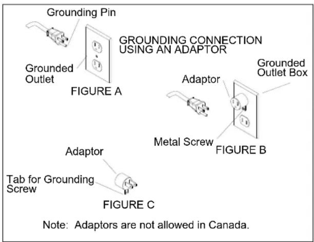
Grounding Instructions:
This appliance must be grounded. If it should malfunction or break down, grounding provides a path of least resistance for electric current to reduce the risk of electric shock. This appliance is equipped with a cord having an equipment-grounding conductor and grounding plug. The plug must be inserted into an appropriate outlet that is properly installed and grounded in accordance with all local codes and ordinances.
This appliance is for use on a nominal 120-volt circuit, and has a grounded plug that looks like the plug in "Fig. A". A temporary adaptor that looks like the adaptor in "Fig. C" may be used to connect this plug to a 2-pole receptacle as shown in "Fig. B", if a properly grounded outlet is not available. The temporary adaptor should be used only until a properly grounded outlet (Fig. A) can be installed by a qualified electrician. The green colored rigid ear, lug, or the like extending from the adaptor must be connected to a permanent ground such as a properly grounded outlet box cover. Whenever the adaptor is used, it must be held in place by a metal screw.
WARNING:
Improper connection of the equipment-grounding conductor can result in a risk of electric shock. Check with a qualified electrician or service person if you are in doubt as to whether the outlet is properly grounded. Do not modify the plug provided with the appliance - if it will not fit the outlet, have a proper outlet installed by a qualified electrician.
▲ AVERTISSEMENT:
Technical Specifications
| ITEM DIMENSION/CAPACITY/MODEL | |
| CONSTRUCTION | Molded UL-recognized PE chassis,tubular steel adjustable handle with diecast aluminum handle housing. |
| MOTOR 1.5 hp | |
| PAD SPEED 1500 rpm | |
| ELECTRICAL SYSTEM: | |
| BDP 51/1500 C 115 volts, 60 Hz | |
| CABLE 75' [22.9 m] | |
| SWITCHES Dual levers with safety lock | |
| WHEELS | Four 5" (12.7 cm) dia., 1.25" (3 cm) wide,non-marking tread |
| HANDLE | 1.5" (4 cm) tubular steel, adjustable,easy to use thumb activated safety lock |
| DIMENSIONS (L X W X H) 31" (80 cm) X 21" (54 cm) X 49" (124 cm) | |
NOTE: Always use a pad, which has been designed for electric ultra high speed burnishing of at least 2000 rpm.
Handle Installation
WARNING:
The handle must be installed by qualified personnel. Read all instructions thoroughly. The machine is shipped with handle unassembled.
AVERTISSEMENT:
The machine is shipped with handle unassembled.
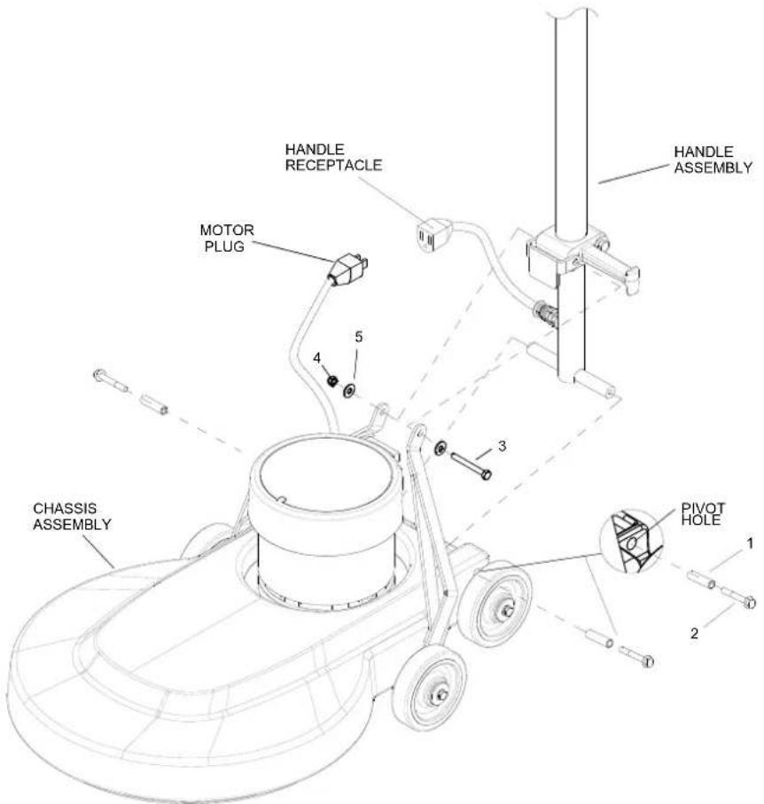
Follow these steps for installation:
- Remove handle and chassis assembly from carton.
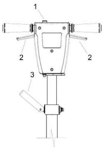
- Attach handle assembly to base using hardware kit (preinstalled in base) items 1 and 2.
NOTE: The bushings (items 1) are required for the correct operation of the handle. The bushings are positioned inside the pivot holes in the chassis, and are held in place by tightening the screws (item 2) against the bushing.
- Remove bolt, nut and washers (items 3, 4 and 5) from lower block on handle assembly. Attach links as shown. Tighten bolt and nut securely, then back off 1/4 to 1/2 turn. Fully tighten bolt and nut on rear of lower block on handle assembly.
- Check handle for movement up and down.
Plug motor cord into handle cord receptacle by routing the cords above the handle links.
Controls
- Safety Lock – Prevents unintended operation of the machine.
- Switch Levers – Turns machine on/off.
- Adjustment Handle – Allows the handle to be adjusted to a comfortable operating position.
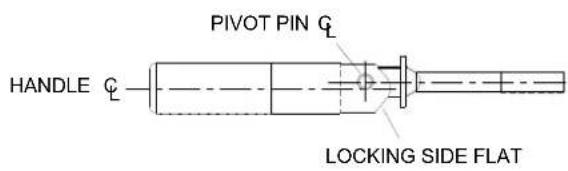
NOTE: It is incorrect to make it lock opposite from the way it was assembled by applying more force to the nut.
The pivot pin is off center in relationship to the axis of the handle. To adjust handle, tighten nut on handle while in the locked position. The handle is locked when the screw is to the outside of the machine and the flat on the opposite side of the handle is flush to the bracket.
Handle Height Adjustment
NOTE: The handle is in the up, locked position from the factory.
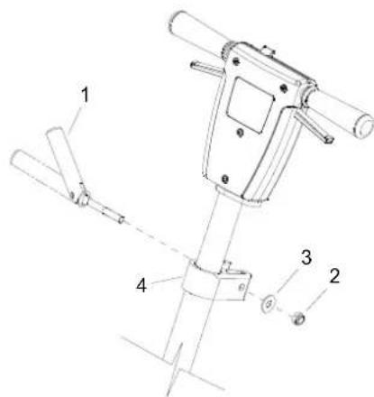
The handle adjust bar (1) for the polishers are individually preset at the factory for optimum locking efficiency and minimum effort of engaging. It should not be necessary to adjust the handle adjust bar unless the handle adjustment bar (1) the washer (3) and nut (2) have been disturbed.
Machine Operation

For indoor use only.

When using the pad, always keep the machine moving when in contact with the floor.

High starting torque. Hold machine firmly with both hands.

- Ensure that the pad driver is in good shape. Install or change pad if necessary.
- Plug the machine into a wall outlet as described in the grounding instructions.
- Lower the handle by unlocking the adjustment handle and moving the handle into position. Relock the handle when it is in a comfortable position.

Insure that handle is locked in position before starting machine.

-
Push the safety lock forward, unlocking the switch levers.
-
With the safety lock forward, squeeze one or both of the switch levers, turning the machine on. (These levers can be operated independently of each other). The safety lock will not re-engage until both levers are released.
- To stop the machine, release the switch levers.
- Do not let machine rest on pad. When finished with the machine, return handle to the storage position.
NOTE: The machine is equipped with a circuit breaker to protect the motor in the event an overload condition occurs. The circuit breaker is located on the handle. Push the reset button to restart the machine. If the breaker trips again, correct the cause of overloading before proceeding.
Maintenance
- Inspect power cord for wear. To prevent electrical shock replace cords with frayed or cracked insulation immediately.
- Place machine in the storage position.
- Check pad condition. Change if soiled or torn.
Pad Installation
- Lay machine back, exposing the under side.
- Remove center lock by turning counterclockwise.
- Ensure pad is centered on pad driver. Pull pad to edge of pad to edge of pad driver in several directions to check for proper engagement.
- Replace center lock by turning clockwise firmly compressing the center of the pad.
Machine Troubleshooting
| PROBLEM CAUSE SOLUTION | ||
| Machine will not run | Circuit breaker tripped in building. | Check and reset. |
| Power switch failure | Test switch for continuity and replace if necessary. | |
| Tripped circuit breaker Reset. | ||
| Faulty power cord Replace. | ||
| Electrical shock | Equipment not grounded | Follow grounding instructions exactly. |
| Receptacle not grounded | Have an electrician inspects building's wiring. | |
| Internal wiring problem | Ensure that the machine wiring matches the appropriate wiring diagram. Replace any wires or components that are short circu-iting. | |
| Repeated circuit breaker tripping | Mechanical problem | Higher amp draws indicate a mechanical problem. Find the problem before using the machine. |
| Faulty circuit breaker | Test circuit for continuity. Replace circuit breaker if necessary. | |
| Excessive vibration | Pad not centered Re-center pad. | |
| Damaged or unevenly worn pad | Replace pad. Do not rest machine on pad when not in use. | |
| Damaged pad driver Replace. | ||
| Pad does not turn but motor is running | Belt is loose or broken Adjust or replace belt. | |
Service Schedule
| MAINTENANCE DAILY MONTHLY | ||
| Check pad wear to prevent buildup of chemicals * | ||
| Check pad driver system for damage * | ||
| Check handles, switches, and knobs for damage * | ||
| Store with pad off the floor * | ||
| Check all bearings for noise * | ||
| Check overall performance of machine * |
| PART NO. | DESCRIPTION | SERIALNO. FROM | NOTES: |
| 86225710 | WASHER, BEARING (HANDLE ADJ) | ||
| 86224740 | SPRING, EXT .5 OD X 3.5L | ||
| 86224750 | SPRING, COMP .48 OD X .91 L | ||
| 86215130 | BAR, HANDLE ADJ | ||
| 86222560 | PIN, PIVOT, HANDLE ADJ | ||
| 86223550 | ROD, HANDLE ADJ | ||
| 86222480 | PAD DRIVER, 20IN BURNISHER FLEX | ||
| 86215330 | BELT, DRIVE 38 IN |