
PMD 7 - Detector BOSCH - Free user manual and instructions
Find the device manual for free PMD 7 BOSCH in PDF.
| Product type | Digital detector |
| Brand | Bosch |
| Model | PMD 7 |
| Article number | 3 603 F81 100 |
| Max. detection depth (ferrous metals) | 70 mm |
| Max. detection depth (non-ferrous metals) | 60 mm |
| Max. detection depth (live copper pipes) | 50 mm |
| Calibration | Automatic and manual |
| Automatic shut-off | After approx. 10 min |
| Operating temperature | 0 °C to +40 °C |
| Storage temperature | -20 °C to +70 °C |
| Max. relative humidity | 80% |
| Power supply | 3 AAA alkaline batteries (1.5 V) |
| Battery life (alkaline batteries) | Approx. 5 h |
| Weight (according to EPTA 01/2003) | 0.1 kg |
| Main functions | Detection of ferrous/non-ferrous metals, live cables (110-240 V AC, 50-60 Hz), audible and visual signal (green/yellow/red), object marking |
| Maintenance and cleaning | Soft, dry cloth; do not use detergents or solvents |
| Safety | Do not use in explosive atmosphere; repairs by qualified personnel using original parts |
| Country of manufacture | Not specified (Bosch Power Tools) |
Frequently Asked Questions - PMD 7 BOSCH
User questions about PMD 7 BOSCH
0 question about this device. Answer the ones you know or ask your own.
Ask a new question about this device
Download the instructions for your Detector in PDF format for free! Find your manual PMD 7 - BOSCH and take your electronic device back in hand. On this page are published all the documents necessary for the use of your device. PMD 7 by BOSCH.
USER MANUAL PMD 7 BOSCH
OBJ BUCH-1913-002.book Page 1 Monday, September 23, 2013 12:30 PM
WEUWEU
Robert Bosch GmbH
Power Tools Division
70745 Leinfelden-Echterdingen
Germany
www.bosch-pt.com
2609140996(2013.09)T/158WEU

PMD7

BOSCH
de Originalbetriebsanleitung
en Original instructions
fr Notice originale
es Manual original
pt Manual original
it Istruzioni originali
nl Oorspronkelijke gebruiskaanwijzing
da Original brugsanvisning
sv Bruksanvising i original
no Original driftsinstruks
fi Alkuperäset ohejeet
elipwoturo oobnyw xphang
tr Original isletmet talimat
ar

2
Deutsch . . . . . . . . . . . . . . . . . . . . . . . . . . . . . . . . . . . . . . . . . . . . . . . . . . . . . . . . . . . . . . .
English 15
Francais . 27
Espanol. Pagina 39
Portugues. Pagina 51
Italiano.. 62
Nederlands.. 73
Dansk. Side 83
Svenska Sida 93
Norsk. Side 103
Suomi. Sivu 113
EAAnyika. 2eAia 123
Türkce Sayfa 135
147.0
PMD 7

4 | Deutsch
Deutsch
Sicherheitshinweise

Henk Becker Helmut Heinzelmann
Executive Vice President Head of Product Cert
Engineering PT/ETM9
a1^2 + a2^2 + a_3^2
Bosch Power Tools 2609140996|(23.9.13)
6 | Deutsch
Robert Bosch GmbH, Power Tools Division
D-70745 Leinfelden-Echterdingen
Read and observe all instructions. SAVE THESE INSTRUCTIONS FOR FUTURE REFERENCE.
Have the measuring tool repaired only through qualified specialists using original spare parts. This ensures that the safety of the measuring tool is maintained.
Do not operate the measuring tool in explosive environments, such as in the presence of flammable liquids, gases or dusts.
Sparks can be created in the measuring tool which may ignite the dust or fumes.

16 | English
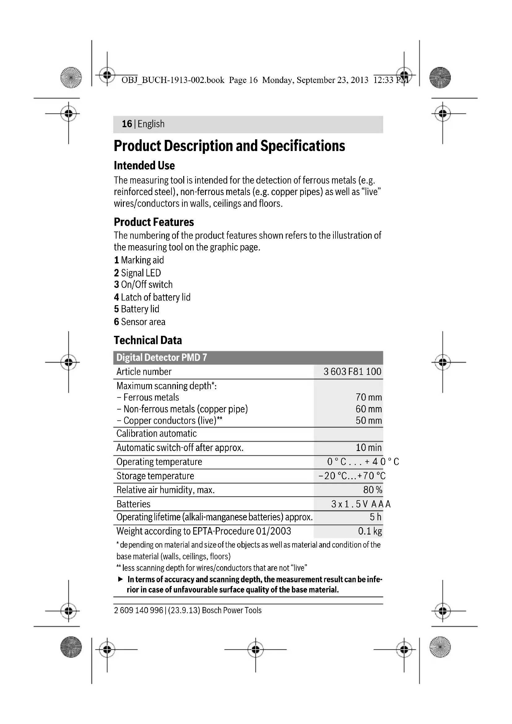
Product Description and Specifications
Intended Use
The measuring tool is intended for the detection of ferrous metals (e.g. reinforced steel), non-ferrous metals (e.g. copper pipes) as well as "live" wires/conductors in walls, ceilings and floors.
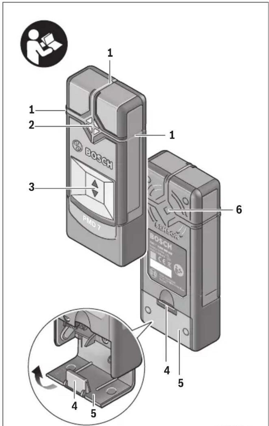
Product Features
The numbering of the product features shown refers to the illustration of the measuring tool on the graphic page.
1 Marking aid
2 Signal LED
3 On/Off switch
4 Latch of battery lid
5 Battery lid
6 Sensor area
Technical Data
| Digital Detector PMD 7 | |
| Article number | 3603 F81 100 |
| Maximum scanning depth*: - Ferrous metals | 70 mm |
| - Non-ferrous metals (copper pipe) | 60 mm |
| - Copper conductors (live)** | 50 mm |
| Calibration automatic | |
| Automatic switch-off after approx. | 10 min |
| Operating temperature | 0°C...+40°C |
| Storage temperature | -20°C...+70°C |
| Relative air humidity, max. | 80% |
| Batteries | 3x1.5V A A A |
| Operating lifetime (alkali-manganese batteries) approx. | 5 h |
| Weight according to EPTA-Procedure 01/2003 | 0.1 kg |
| * depending on material and size of the objects as well as material and condition of the base material (walls, ceilings, floors) ** less scanning depth for wires/conductors that are not “live” In terms of accuracy and scanning depth, the measurement result can be inferior in case of unfavourable surface quality of the base material. | |
English | 17
Declaration of Conformity

We declare under our sole responsibility that the product described under "Technical Data" is in conformity with the following standards or standardisation documents:
EN61010-1:2010-10,EN61326-1:2006-05
EN 301489-3:2002-08, EN 301489-1:2011-09,
EN 300330-1:2010-02, EN 300330-2:2010-02 according to the provisions of the directives 2011/65/EU, 1999/5/EC.
Henk Becker Helmut Heinzelmann
Executive Vice President Head of Product Certification
Engineering PT/ETM9

Robert Bosch GmbH, Power Tools Division
D-70745 Leinfelden-Echterdingen
Inserting/Replacing the Batteries
Alkali-manganese batteries are recommended for the operation of the measuring tool.
To open the battery lid 5, press on the latch 4 and fold the battery lid up. Insert the batteries. When inserting, pay attention to the correct polarity according to the representation on the inside of the battery compartment.
If the measuring tool is not used for longer periods of time, remove the batteries. The batteries can corrode or self-discharge after prolonged storage.
Operation
Initial Operation
Protect the measuring tool against moisture and direct sun light.
Do not subject the measuring tool to extreme temperatures or variations in temperature. As an example, do not leave it in vehicles for
Bosch Power Tools 2609140996|(23.9.13)


18|English
long time. In case of large variations in temperature, allow the measuring tool to adjust to the ambient temperature before putting it into operation. In case of extreme temperatures or variations in temperature, the accuracy of the measuring tool can be impaired.
Avoid heavy impact to or falling down of the measuring tool.
Switching On and Off
Before switching the measuring tool on, make sure that the sensor area 6 is not moist. If required, dry the measuring tool using a soft cloth.
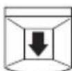
To switch on the measuring tool, slide the On/Off switch 3 downwards.
After a short self-test, the tool is ready for use. The readiness of use is indicated when the signal LED 2 illuminates. If the signal LED 2 fails to illuminate after switching on the tool, you must replace the batteries.
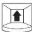
To switch off the measuring tool, slide the On/Off switch 3 upwards.
When no measurements are carried out for approx. 10 minutes, the measuring tool switches off automatically in order to extend the service life of the batteries.
Note: If the measuring tool has automatically switched off, then the On/Off switch 3 will still be in the "On" position. To switch the measuring tool back on, first slide the On/Off switch 3 into the position "Off" and then back into the position "On".
Operating Modes
The measuring tool detects objects below the sensor area 6.
Before drilling, sawing or routing into a wall, protect yourself against hazards by using other information sources. As the accuracy and scanning depth of the measuring tool can be reduced due to environmental conditions or the wall material, there is a risk that objects may be within the sensor range, even if the display does not indicate an object (the signal LED 2 illuminates green).

English | 19
Signal LED Explanation
| green | no object detected |
| yellow | - metal object in the vicinity of the sensor - small or low-lying metal object within the sensor area or - impairment of the sensor due to unfaithful wall material |
| red and continuous tone | metal object detected in the sensor area |
| red flashing (fast) and intermittent sound | “live” wire/conductor detected |
Detecting Metal Objects
After switching on, the signal LED 2 lights up green.
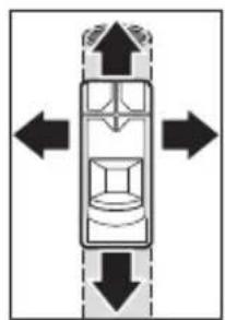
Position the measuring tool on/against the surface being detected and move it sideways.
- If no metal object is visible in the base material, then the signal LED 2 continues to illuminate green and no signal tone sounds.
- When the measuring tool comes closer to a metal object, the signal LED 2 first lights up yellow and changes to red the closer it comes to the metal object. As soon as the signal LED lights up red, a signal tone is also emitted, the pitch of which rises the closer it comes to the metal object.
- Over a metal object, the signal LED 2 illuminates red and a signal tone is emitted at maximum pitch.
- Even with a yellow signal LED 2, a metal object may be located below the sensor area. Small or low-lying metal objects are located in the vicinity of the sensor or the wall material impairs the measurement results.
After moving over the surface the first time, the position of the metal object is only roughly indicated. If you move the measuring tool over the metal object several times, the object detection will become increasingly precise. After moving over the metal object several times (without lifting the measuring tool from the base material), its position can be indicated very accurately: if the signal LED 2 illuminates red and the signal
tone sounds, the metal object is below the sensor area. When the pitch of the signal tone is highest, the metal object is located below the centre of the sensor.


20 | English
Scanning for "Live" Wires
The measuring tool indicates wires, which carry voltage between 110V and 240V and a frequency corresponding to the widely used standard (AC with 50 or 60Hz ). Other wires (carrying DC, higher/ lower frequency or voltage) as well as non-"live" wires/conductors cannot be found reliably, but are possibly indicated as metal objects.
The detection for "live" wires/conductors takes place automatically with every measurement. When a "live" wire/conductor is detected, the signal LED 2 flashes red and an intermittent signal tone sounds with rapid tone sequence. Move the measuring tool repeatedly over the surface to locate the "live" wire/conductor more precisely. After moving over the surface several times, the position of the "live" wire/conductor can be indicated very accurately.
"Live" wires/conductors can be detected more easily when power consumers (e.g. lamps, appliances) are connected to the wire being sought and switched on.
Note: Always ensure that you hold the measuring tool firmly without gloves to enable a good grounding. Also ensure that ladders/scaffolding must be grounded. Avoid ladders/scaffolding whose supports have plastic caps underneath them. Do not wear insulating footwear.
Under certain conditions (e.g. below metal surfaces or behind surfaces with high water content), "live" wires/conductors cannot be securely detected. When the signal LED 2 illuminates yellow or red over a larger area, then the material is screening-off electrically and the detection for "live" wires/conductors is not reliable.
Working Advice
- Measuring values can be impaired through certain ambient conditions. These include, e.g., the proximity of other equipment that produce strong magnetic or electromagnetic fields, moisture, metallic building materials, foil-laminated insulation materials or conductive wallpaper or tiles. Therefore, please also observe other information sources (e.g. construction plans) before drilling, sawing or routing into walls, ceilings or floors.
Note: Do not hold the device in the area of the sensor, so as not to affect the measurement. This achieves more accurate measurement results.

English | 21
Marking Objects
Detected objects can be marked as required. The outer edges of an object are indicated by the colour change of the signal LED 2 from yellow to red. The centre of the metal object can be determined by the pitch. Using a pen, mark the sought after location at the top and the side marker aids 1.
Continuous Flashing Green/Yellow/Red
If the signal LED 2 flashes alternately green, yellow and red, even when no metal object or no "live" cable is in the vicinity, the measuring device must be sent in for service.
Maintenance and Service
Manual Calibration
If the signal LED 2 illuminates red or yellow, even when no metal is in the vicinity of the measuring tool, the tool must be recalibrated.
- To do this, switch the measuring device on using the On/Off switch 3.
- Remove a battery from the switched on measuring device.
- While the battery is removed, switch the measuring device off using the On/Off switch 3.
- Reinsert the batteries into the measuring device (pay attention to the polarity!)
- Now remove all objects in the vicinity of the measuring device (including wrist watches or rings of metal) and hold the measuring tool up in the air.
- Switch the measuring device on using the On/Off switch 3 and off again within 3 seconds. The signal LED 2 of the measuring device will flash red in slow succession during the 3 seconds to indicate that it is ready to calibrate.
- Switch the measuring device back on within 0.5 seconds. The calibration is initiated and takes about 6 seconds. The signal LED 2 will flash green for 6 seconds in quick succession, the calibration is being performed. Now the device is once more ready for operation and the signal LED 2 illuminates solid green.
Note: If the sequence of switching off then on again is not followed, no calibration is performed. The signal LED 2 remains either yellow or red, even though no metal is located within the vicinity. In this case, repeat the calibration.

22 | English
Troubleshooting - Causes and Corrective Measures
Cause Corrective Measure
Signal LED 2 does not illuminate
| Measuring tool is not switched on | Slide the On/Off switch into position “On”. |
| Measuring tool has switched itself off | Slide the On/Off switch first into position “Off” and then into position “On”. |
| Batteries have not been inserted or been inserted incorrectly | Insert batteries. Pay attention to the polarity. |
| Flat or rechargeable batteries inserted | Replace batteries. Do not use rechargeable batteries. |
Signal LED 2 illuminates yellow or red, even though no metal is located within the vicinity (warning of metal objects)
Ambient temperature is too high/too low Only use the measuring tool within the specific temperature range of 0^ - 40^
Severe temperature change Wait until the measuring tool acclimates to the ambient temperature.
Auto calibration not Perform a manual calibration. successful
Signal LED 2 lights yellow or red over large measuring area on the wall (warning of metal objects)
| Many, closely spaced metal objects | Pay attention to the pitch of the signal sound to differ- entiate between individual metal objects. Metal objects that are too closely spaced, cannot be de- tected separately.* |
| Metal as building material | A reliable detection is not possible with metallic building materials (e.g. foil-laminated insulation materials, heat sinks).* |
Auto calibration not Perform a manual calibration. successful
English | 23
Cause Corrective Measure
Signal LED 2 flashes red over a large measuring area on the wall (warning of "live" cables)
| Improper grounding of the wall | With your free hand, touch the wall at a distance of 20 -30 cm from the measuring tool to ground the wall. |
"Live" cable is not found
| No/atypical voltage on the cable | Add voltage to the cable, for example by turning on light switches assigned to it. The detection of cables with AC voltages outside of the range 110 – 240 V, 50 – 60 Hz is not reliably possible.* |
| Cable is located too deep | The scanning depth is dependent on the building material and may be less than the maximum scanning depth.* |
| Cable runs in grounded metal pipe | Use the measuring tool to locate the metal pipe. |
| Measuring tool is not grounded | Hold the measuring tool firmly without gloves. Do not stand on insulating ladders or scaffolding. Do not wear insulating footwear. |
| Screened-off building material or high air humidity | A reliable detection is not possible with metallic or moist building materials (e.g. at high air humidity).* |
Metal object is not located
| Metal object is locat-ed too deep | The scanning depth is dependent on the building material and may be less than the maximum scanning depth.* |
| Metal object is too small | The scanning depth is dependent on the building material and may be less than the maximum scanning depth.* |
Uncoordinated flashing in colours green, yellow, red
| Interference caused by electric or magnetic fields | Keep your distance from devices emitting strong electric or magnetic fields (e.g. computers, switch mode power supplies). |
24|English
Cause Corrective Measure
Measurement results inaccurate/implausible
| Interfering metal objects in the area of the sensor | Remove all interfering metal objects (e.g. watch, bracelet, ring, etc.) from the sensor area. Do not hold the device close to the sensor. |
Auto calibration not Perform a manual calibration. successful
Continuous flashing green/yellow/red, even when no metal or "live" cable is in the vicinity.
Measuring tool is Send the measuring tool in for service. defective
- Therefore, please also observe other information sources (e.g. construction plans) before drilling, sawing or routing into walls, ceilings or floors.
Maintenance and Cleaning
Wipe away debris or contamination with a dry, soft cloth. Do not use cleaning agents or solvents.
In order not to affect the measuring function, decals/stickers or name plates, especially metal ones, may not be attached in the sensor area 6 on the front or back side of the measuring tool.
After-sales Service and Application Service
Our after-sales service responds to your questions concerning maintenance and repair of your product as well as spare parts. Exploded views and information on spare parts can also be found under:
www.bosch-pt.com
Bosch's application service team will gladly answer questions concerning our products and their accessories.
In all correspondence and spare parts orders, please always include the 10-digit article number given on the type plate of the measuring tool.
English | 25
Great Britain
Robert Bosch Ltd. (B.S.C.)
P.O.Box 98
Broadwater Park
North Orbital Road
Denham
Uxbridge
UB95HJ
Tel. Service: (0844) 7360109
Fax: (0844) 7360146
E-Mail: boschservicecentre@bosch.com
Ireland
Origo Ltd.
Unit 23 Magna Drive
Magna Business Park
City West
Dublin 24
Tel. Service: (01) 4666700
Fax: (01) 4666888

Australia, New Zealand and Pacific Islands
Robert Bosch Australia Pty. Ltd.
Power Tools
Locked Bag 66
Clayton South VIC 3169
Customer Contact Center
Inside Australia:
Phone: (01300) 307044
Fax: (01300) 307045
Inside New Zealand:
Phone: (0800) 543353
Fax: (0800) 428570
Outside AU and NZ:
Phone: +61 395415555
www.bosch.com.au
Republic of South Africa
Customer service
Hotline: (011) 6519600
Bosch Power Tools 2609140996|(23.9.13)


26 | English
Gauteng - BSC Service Centre
35 Roper Street, New Centre
Johannesburg
Tel.: (011) 4939375
Fax: (011) 4930126
E-Mail: bsctools@icon.co.za
KZN - BSC Service Centre
Unit E, Almar Centre
143 Crompton Street
Pinetown
Tel.: (031) 7012120
Fax: (031) 7012446
E-Mail: bsc.dur@za.bosch.com
Western Cape - BSC Service Centre
Democracy Way, Prosperity Park
Milnerton
Tel.: (021) 5512577
Fax: (021) 5513223
E-Mail: bsc@zsd.co.za
Bosch Headquarters
Midrand, Gauteng
Tel.: (011) 6519600
Fax: (011) 6519880
E-Mail: rbsa-hq.pts@za.bosch.com
Disposal
Measuring tools, accessories and packaging should be sorted for environmental-friendly recycling.
Do not dispose of measuring tools and batteries/rechargeable batteries into household waste!
Only for EC countries:

According to the European Guideline 2012/19/EU, measuring tools that are no longer usable, and according to the European Guideline 2006/66/EC, defective or used battery packs/batteries, must be collected separately and disposed of in an environmentally correct manner.
Francais|27
Batteries no longer suitable for use can be directly returned at:
Great Britain
Robert Bosch Ltd. (B.S.C.)
P.O.Box 98
Broadwater Park
North Orbital Road
Denham
Uxbridge
UB95HJ
Tel. Service: (0844) 7360109
Fax: (0844) 7360146
E-Mail: boschservicecentre@bosch.com
Subject to change without notice.

Français
Executive Vice President Head of Product Certification
Engineering PT/ETM9

Robert Bosch GmbH, Power Tools Division
D-70745 Leinfelden-Echterdingen
Henk Becker Helmut Heinzelmann
Executive Vice President Head of Product Certification
Engineering PT/ETM9
a1^2 + a2^2
Robert Bosch GmbH, Power Tools Division
D-70745 Leinfelden-Echterdingen
Leinfelden, 26.08.2013
Montaje
Executive Vice President
Engineering
Helmut Heinzelmann
Head of Product Certification
PT/ETM9

Robert Bosch GmbH, Power Tools Division
D-70745 Leinfelden-Echterdingen
Executive Vice President Head of Product Certification
Engineering PT/ETM9

Bosch Power Tools 2609140996|(23.9.13)


64 | Italiano
Robert Bosch GmbH, Power Tools Division
D-70745 Leinfelden-Echterdingen
Executive Vice President
Head of Product Certification
Engineering
PT/ETM9
a1^2 + a2^2
2609140996|(23.9.13) Bosch Power Tools


Nederlands | 75
Robert Bosch GmbH, Power Tools Division
D-70745 Leinfelden-Echterdingen
Henk Becker Helmut Heinzelmann
Executive Vice President Head of Product Certification
Engineering PT/ETM9
f_ ≥ 0 i. V. 阅
Robert Bosch GmbH, Power Tools Division D-70745 Leinfelden-Echterdingen Leinfelden, 26.08.2013
Montering
Bosch Service Center
Telegrafvej 3
2750 Ballerup
TIf. Service Center: 44898855
Fax:44898755
E-Mail: vaerktoej@dk.bosch.com
2609 140 996 | (23.9.13) Bosch Power Tools


Svenska|93
Bortskaffelse
Executive Vice President Head of Product Certification
Engineering PT/ETM9
f^ ( x) = 1x - x + 1 = 1x( -x)
Robert Bosch GmbH, Power Tools Division
D-70745 Leinfelden-Echterdingen
Bosch Service Center
Telegrafvej 3
2750 Ballerup
Danmark
Tel.: (020) 414455 (inom Sverige)
Fax: (011) 187691


Norsk | 103
Avfallschantering
Endast for EU-lander:

Executive Vice President Head of Product Certification
Engineering PT/ETM9
a1^2 + a2^2
Robert Bosch GmbH, Power Tools Division
D-70745 Leinfelden-Echterdingen
Henk Becker Helmut Heinzelmann
Executive Vice President Head of Product Certification
Engineering PT/ETM9
a1^2 + a2^2
Robert Bosch GmbH, Power Tools Division
D-70745 Leinfelden-Echterdingen
Leinfelden, 26.08.2013
Asennus
Executive Vice President Head of Product Certification
Engineering PT/ETM9

Robert Bosch GmbH, Power Tools Division
D-70745 Leinfelden-Echterdingen
Executive Vice President Head of Product Certification Engineering PT/ETM9
a1^2 + a2^2
2609140996|(23.9.13) Bosch Power Tools


Türkce|137
Robert Bosch GmbH, Power Tools Division
D-70745 Leinfelden-Echterdingen
Bosch San. ve Tic. A.S.
Ahi Evran Cad. No:1 Kat:22
Polaris Plaza
80670 Maslak/Istanbul
BoschUzmanEkibi ^+ 90(0212)3671888
Isiklar LTD. STI.
Kizilay Cad. No: 16/C Seyhan
Adana
Tel.: 0322 3599710
Tel.: 0322 3591379
a a a a a a a a a a a a a a a a a a a a a a a a a a a a a a a a a a a a a a a a a a a a a a a a a a a a a a a a a a aaa
:ba 1gjgJl JgJ

2012/19/EU 2012/19/EU 2012/19/EU 2012/19/EU 2012/19/EU 2012/19/EU 2012/19/EU 2012/19/EU 2012/19/EU 2012/19/EU 2012/19/EU

.山
Bosch Power Tools 2609140996|(23.9.13)

jg jgs g jgl uu y
jc aqls aolwosgag lcbal
Lgio gai jgai
(ajgai) aeg aasblgo gl ayus
.(glllglg
g 1 g
aJgso Jc/aaojS Jc waiJI eW
aagall aasssll pwsy jg s yj 1o (dlag pia jlgw dclw li0) 1o jlgll lww .wluall Jso .wluall no b
g aagaae oLwJ 1uWJU
.ugy oJyoo aulac yjy p
gwsu gssoo LSSJ aJgao
| üjüjüjüjüjüjüjüjüjüjüjüjüjüjüjüjüjüjüjüjüjüjüjüjüjüjüjüjüjüjüjüjüjüjüjüjüjüjüjüjüjüjüjüjüjüjüjüjüjüjü |
| .üjüjüjüjüjüjüjüjüjüjüjüjüjüjüjüjüjüjüjüjüjüjüjüjüjüjüjüjüjüjüjüjüjüjüjüjüjüjüjüjüjüjüjüjüjüjüjüjüjüJ |
afo jc wlaol osc
| a,b,||g| a,i,do||i,j,l,g o g |
| 2(a||l,l||g||g,b)||la||j,l||o) |
| sa,i j k w l a w s l a u l o c ||j l j l s o |
| * .dulc |
a g b j g i a j l c s u o s o a j l c g
juaa jui
| gac bji |
| gac ij |
Jggo jseal pwnll 1s gac lc
Bosch Power Tools 2609140996|(23.9.13)
150|
U|JgUw-1
2 1
| العربية الحرفية مصحيى مصحيى مصحيى مصحيى مصحيى مصحيى مصحيى مصحيى مصحيى مصحيى مصحيى مصحيى مصحيى مصحيى مصحيى مصحيى مصحيى مصحيى مصحيى مصحيى مصحيى مصحيى مصحيى مصحيى مصحيى مصحي弩 مصحي弩 مصحي弩 مصحي弩 مصحي弩 مصحي弩 مصحي弩 . . . . . . . . . . . . . . . . . . . . . . . . . . . . . . . . . . . . . . . . . . . . . . . . . . . . . . . . . . . . . . . . . . . . . . . . . . . . . . . . . . . . . . . . . . . . . . . . . . . . g g g g g g g g g g g g g g g g g g g g g g g g g g g g g g g g g g g g g g g g g g g g g g g g g g g | |
| العربية الحرفية مصحيى مصحيى مصحيى مصحيى مصحيى مصحيى مصحيى مصحيى مصحي弩 . . . . . . . . . . . . . . . . . . . . . . . . . . . . . . . . . . . . . . . . . . . . . . . . . . . . . . . . . . . . . . . . . . . . . . . . . . . . . . . . . . . . . . . . . . . . . . g g g | |
| العربية الحرفية مصحيى مصحيى مصحيى مصحي弩 . . . g g g g g g g g g g g g g g g g g g g g g g g g g g g g g g g g g g g g g g g g g g g g g g g g 2 g g g g g g g g g g g g g g g g g g g g g g g g g g g g g g g g g g g g g g g g g g g g g g g g g g 2 g 2 g g g g g g g g g g g g g g g g g g g g g g g g g g g g g g g g g g g g g g g g g g g g g g g g g | |
| g g g g g g g g g g g g g g g g g g g g g g g g g g g g g g g g g g g g g g g g g g g g g g g g g g | g g g g g g g g g g g g g g g g g g g g g g g g g g g g g g g g g g g g g g g g g g g g g g g g g 2 2 g 2 g 2 g 2 g 2 g 2 g 2 g 2 g 2 g 2 g 2 g 2 g 2 g 2 g 2 g 2 g 2 g 2 g 2 g 2 g 2 g 2 g 2 g 2 g 2 g 2 g 2 g 2 g 2 g 2 g 2 g 2 g 2 g 2 g g g g g g g g g g g g g g g g g g g g g g g g g g g g g g g g g g g g g g g g g g g g g g g 2 g 2 g 2 g 2 g 2 g 2 g 2 g 2 g 2 g 2 g 2 g 2 g 2 g 2 g 2 g 2 g 2 g 2 g 2 g 2 g 2 g 2 g 2 g 2 g 2 g 2 g 2 g 2 g 2 g 2 g 2 g 2 g 2 g |
| g g g g g g g g g g g g g g g g g g g g g g g g g g g g g g g g g g g g g g g g g g g g g g g g 2 g 3 g 3 g 3 g 3 g 3 g 3 g 3 g 3 g 3 g 3 g 3 g 3 g 3 g 3 g 3 g 3 g 3 g 3 g 3 g 3 g 3 g 3 g 3 g 3 g 3 g 3 g 3 g 3 g 3 g 3 g 3 g 3 g 3 g 3g 3 g 3 g 3 g 3 g 3 g 3 g 3 g 3 g 3 g 3 g 3 g 3 g 3 g 3 g 3 g 3 g 3 g 3 g 3 g 3 g 3 g 3 g 3 g 3 g 3 g 3 g 3 g 3 g 3 g 3 g 3 g 3 g 3 g | g g g g g g g g g g g g g g g g g g g g g g g g g g g g g g g g g g g g g g g g g g g g g g g g g 4 g 4 g 4 g 4 g 4 g 4 g 4 g 4 g 4 g 4 g 4 g 4 g 4 g 4 g 4 g 4 g 4 g 4 g 4 g 4 g 4 g 4 g 4 g 4 g 4 g 4 g 4 g 4 g 4 g 4 g 4 g 4 g 4 g 4 g |
| . g g g g g g g g g g g g g g g g g g g g g g g g g g g g g g g g g g g g g g g g g g g g g g g g g g | p l l l l l l l l l l l l l l l l l l l l l l l l l l l l l l l l l l l l l l l l l l l l l l l l l l l l l l l l l l l l l l l l l l l l l l l l l l l l l l l l l l l l l l l l l l l l l l l l l l l l |
2609140996|(23.9.13)BoschPowerTools
JAL/1JAL/JJALJgUJI JIJI
Jg Jg 2 g 2000000000000000000000000000000000000000000
aJj jUJI JI JUJI UJI
ddJg dJ
a g d J oJ L aJ
gds yd g wll ooc lcll s dal: abdo 1c 11 1a0o000000000000000000000000000000000000000000000000000000000000000000000000000000000
abwI calg aJdall bawI cala 10) gjbl Jb jy I yI yI yI yI yI yI yI yI yI yI yI yI yI yI yI yI yI yI yI yI yI yI yI yI yI yI yI yI yI yI yI yI yI yI yI yI yI yI yI yI yI yI yI yI yI yI yI yI yI yI y
Jshu
Igblgbll 15g (J/1c21 s jll gJgJj
duc Soio Jsuu Iquc loe jull pui x a y Lus qLs
Henk Becker
Executive Vice President Engineering
Helmut Heinzelmann
Head of Product Certification
PT/ETM9

Robert Bosch GmbH, Power Tools Division
D-70745 Leinfelden-Echterdingen