
F220-B6C - Detector BOSCH - Free user manual and instructions
Find the device manual for free F220-B6C BOSCH in PDF.


| Product Type | Smoke Detector |
| Brand | Bosch |
| Model | F220-B6C |
| Detection Technology | Photoelectric |
| Power Source | 9V DC battery (alkaline) |
| Dimensions (D x H) | 120 mm x 40 mm |
| Weight | 150 g (without battery) |
| Alarm Volume | 85 dB at 3 m |
| Operating Temperature Range | 0°C to 40°C |
| Humidity Range | 10% to 95% RH (non-condensing) |
| Compliance | EN 14604, CE |
| Test/Reset Button | Yes |
| Low Battery Warning | Chirp every 45 seconds |
| End of Life Warning | Chirp every 30 seconds after 10 years |
| Mounting Type | Ceiling or wall mount |
| Included Accessories | Mounting bracket, screws, wall plugs, 9V battery |
| Maintenance | Vacuum dust from vents monthly; test weekly |
| Battery Replacement | At least once a year or when low battery warning sounds |
| Clean with | Soft brush or dry cloth; do not use water or cleaners |
| Product Life | 10 years from date of manufacture |
| Repairability | Battery replaceable; other repairs not recommended – replace unit |
Frequently Asked Questions - F220-B6C BOSCH
User questions about F220-B6C BOSCH
0 question about this device. Answer the ones you know or ask your own.
Ask a new question about this device
Download the instructions for your Detector in PDF format for free! Find your manual F220-B6C - BOSCH and take your electronic device back in hand. On this page are published all the documents necessary for the use of your device. F220-B6C by BOSCH.
USER MANUAL F220-B6C BOSCH
natural_image
Interior view of a fire safety device showing three connected outlets with visible circuit boards and wiring (no text or symbols)F220 Series Detectors with F220-B6/C/E/R Bases
Installation Manual

BOSCH
en English manual
1 L e g a l
1.1 Trademarks
CleanMe ^® is a registered trademark of GE Interlogix in the United States and/or other countries.
Chamber Check ^® is a registered trademark of Bosch Security Systems, Inc. in the United States.
Chambermaid ^™ is a trademark of Bosch Security Systems, Inc. in the United States.
ENVI-RO-TECH™ is a trademark of Tech Spray L.P.
TECHSPRAY ^® is a registered trademark of Tech Spray L.P.
1.2 Required Maintenance and Testing
Keep the detector calibrated for proper operation. NFPA 72, The National Fire Alarm Code, recommends performing calibration tests at installation, then every other year.
Depending on local regulations, calibration testing might be required more than once a year.
Perform functional testing yearly.

NOTE! Notify all concerned parties before any maintenance or testing of the fire alarm system and upon completion of these activities.
Test the calibration (to meet NFPA 72) using either the magnet test or measuring the calibration with a calibrated product from No Climb Products Ltd. Quickly determine the calibration by a visual inspection of the detector's LED (refer to Section 4.4
Flash Rate and Trouble Indication on page 22). These tests confirm whether or not the detector is within its factory marked calibration range.
At least once a year vacuum or wipe the external part of the detector clean. Pay particular attention to the detector screens in areas of heavy insect activity or dust. To clean the chamber,
use a can of clean, dry compressed air (such as TECHSPRAY ENVI-RO-TECH Duster) which is available at office and alarm supply stores. Shorten the plastic tube that comes with the compressed air to about 2 in. (5 cm). Place the tube or needle valve through the Chambermaid valve in the bottom of the detector (refer to Figure 2.2 on page 7).

NOTE! Do not paint the detectors. Paint or other foreign matter covering the detector can prevent smoke detection.
2 General Information
This document covers mounting, wiring, power requirements, testing, and maintenance for the F220-B6, F220-B6C, F220-B6E, and F220-B6R Detector Bases and the F220 Series Heat and Photoelectric Smoke Detectors. Install them according to NFPA 72.

NOTE! For proper system installation, read and understand NFPA-72 before installation.
For installation guidelines, refer to Installation Considerations for Smoke and Fire Detectors (P/N: 26715).
2.1 F220-B6 Series Detector Bases
2.1.1 Compatible Control Panels
Two-wire:

NOTE! Bosch Security Systems, Inc. makes no claim written, oral, or implied that the F220 Series Detectors work with any two-wire control panels except those specified in the Base Compatibility chart in Technical Service Note (P/N: 4998148185).
Four-wire: Compatible with all UL Listed four-wire control panels. Refer to the control panel manufacturer's installation instructions for proper end-of-line (EOL) resistor selection.
2.1.2 Base Comparisons
The F220-B6 is a two-wire base, while the F220-B6C, F220-B6E, and F220-B6R are four-wire bases. All three of the four-wire bases have a Form A alarm relay. In addition to the alarm relay, the:
- F220-B6C has a Form C auxiliary alarm relay
- F220-B6E has a power supervision (EOL) relay

NOTE! Use the F220-B6RS when a built-in sounder is needed. The F220-B6RS also has a Form A alarm relay. Refer to the F220 Series Detectors with the F220-B6RS Installation Manual (P/N: F01U029847).
For addressable systems, use the F220-B6PM Addressable POPIT Master Base or F220-B6PS Addressable POPIT Base. Refer to the F220-B6PS/M Installation Manual (P/N: 4998149982).
2.1.3 Base Features
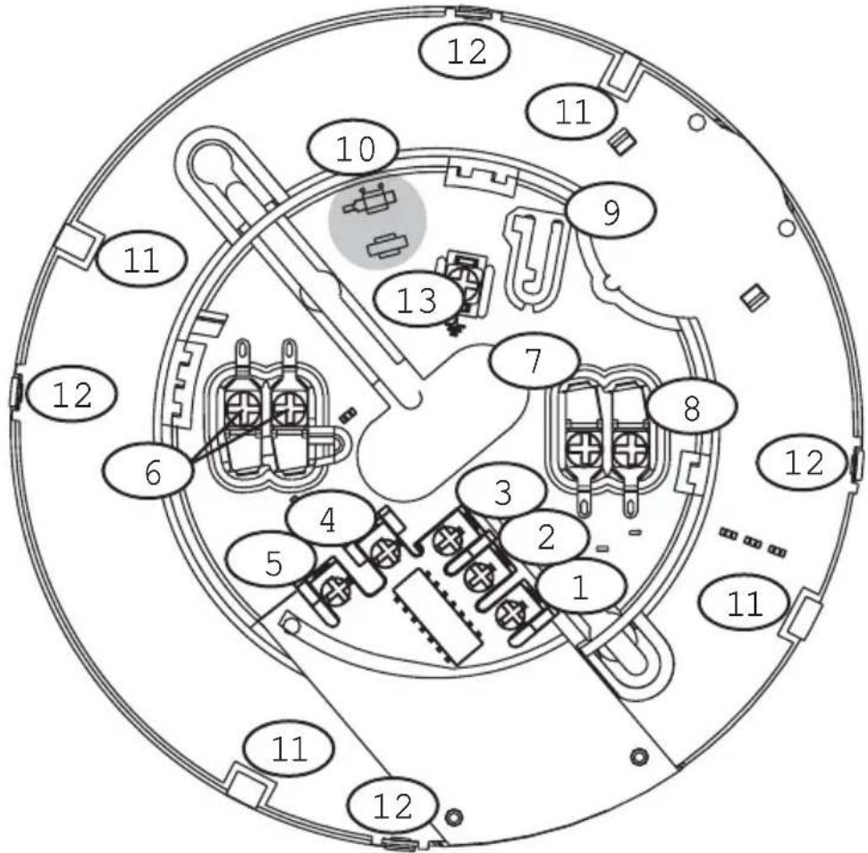
| 1. Terminal 12. Terminal 23. Terminal 34. Terminal 45. Terminal 56. Resettable Auxiliary Power Positive (+) In and Out Terminals (b1 and b2)7. Resettable Auxiliary Power Negative (-) In and Out Terminal (a1/a2) | 8. Remote Terminal (c)9. Tamper Tab (Locking Bar)10. Tamper Tab (Locking Bar Mount)11. Alignment Key (4 places)12. Snap Lock (4 places)13. Earth Shield Terminal (optional) |
Fig.2.1 Base Features
2.2 F220 Series Detectors
2.2.1 About F220 Series Detector Heads
The F220 Series Detector Heads listed in Table 2.1 each require an F220-B6 Series Base.

WARNING! The F220-PTHC detects carbon monoxide (CO) as a component of a fire. Do not use the F220-PTHC as a stand-alone CO detector.
| F220-135 | Electronic heat detector 135°F (57°C), fixed temperature and rate-of-rise |
| F220-135F | Electronic heat detector 135°F (57°C), fixed temperature only |
| F220-190F | Electronic heat detector 190°F (88°C), fixed temperature only |
| F220-P Photoelectric smoke detector | |
| F220-PTH | Photoelectric smoke detector with integral 135°F (57°C) heat sensor |
| F220-PTHC | Photoelectric smoke detector with integral 135°F (57°C) heat sensor and CO enhanced smoke detection |
Table2.1F220 Series Detector Heads
2.2.2 F220 Series Detector Features
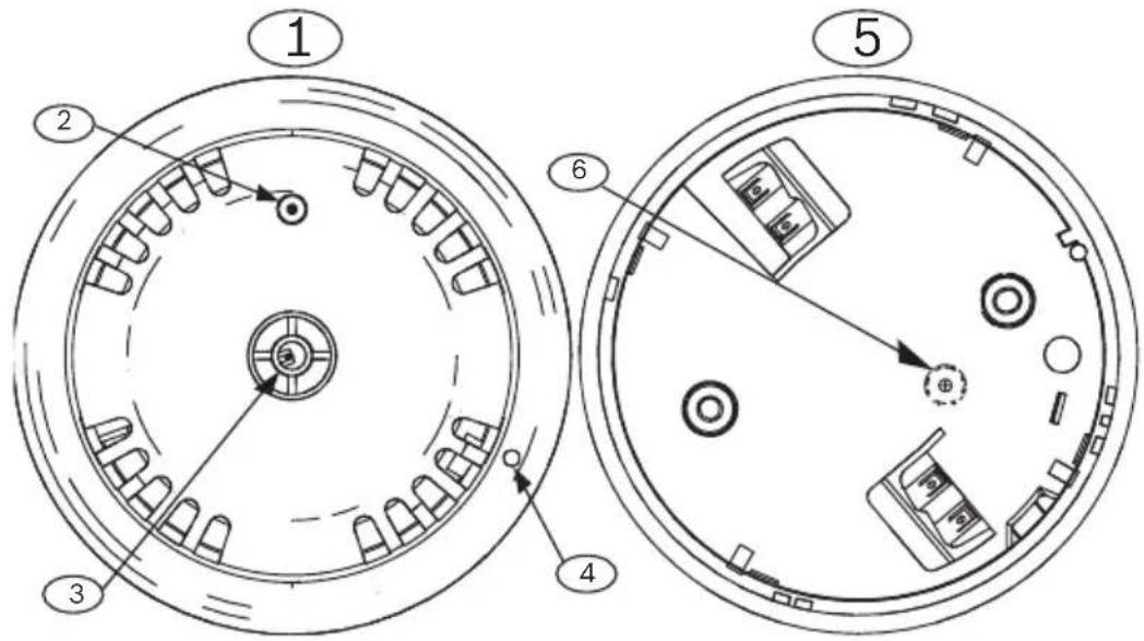
| 1. Front of detector2. Light-emitting diode (LED)3. Thermistor(heat detectors only) | 4. Unlocking port5. Back of detector6. Chambermaid location |
Fig.2.2 Detector Features
2.2.3 F220 Series Heat Detector Heads
The F220 Heat Detector Heads can be identified by color coding (refer to Table 2.2).
| F220-135 No | circle around the thermistor |
| F220-135F A | gray circle around the thermistor |
| F220-190F A | black circle around the thermistor |
Table2.2 Distinguishing Heat Detectors

WARNING! The F220-135, F220-135F and F220-190F are not life safety devices. Use them with F220-B6 Series bases to provide general property protection.
2.2.4 F220 Series Smoke Detector Heads
The F220 Series Smoke Detector Heads are UL Listed, open-area photoelectric smoke detectors that work with commercial fire protective signaling systems and household fire warning systems. Select the appropriate mounting base to configure the detectors for two-wire or four-wire versions (refer to Section 2.1.2 Base Comparisons on page 4).
To verify power to the detector and a functioning smoke sampling circuitry, a dual color LED indicator flashes green every eight seconds when operating normally. It flashes once every four seconds when a trouble condition exists. If the detector determines an alarm condition exists, the LED changes from flashing green to steady red. The detector returns to normal when power is interrupted and the alarm condition clears.
Throughout its normal life cycle, the smoke detector monitors and periodically adjusts itself to keep the sensitivity at its factory calibrated level. When excessively dirty, the detector's LED flash rate changes from an eight second flash rate to a four second rate. If CleanMe is selected, the detector sends a CleanMe signal to the compatible control panel to indicate a dirty smoke detector.
Refer to Section 4.3 Set CleanMe Feature on page 22.
2.3 Technical Specifications
2.3.1 General Specifications
| Air Velocity 400 ft/min (1200 m/min) maximum | |
| Operating Temperature | +32°F to 100°F (0°C to 38°C) |
| Relative Humidity | 0% to 95% (non-condensing) |
Table2.3 Specifications - Detectors and Bases
2.3.2 Base Specifications
| Alarm Current (only base current, detector current excluded) | |
| F220-B6: Two-wire base; no base current | |
| F220-B6C: 31 mA at 12 VDC | 35 mA at 24 VDC40 mA maximum at 30 VDC |
| F220-B6E: 25 mA at 12 VDC | 30 mA at 24 VDC34 mA maximum at 30 VDC |
| F220-B6R: 13.5 mA at 12 VDC | 16.5 mA at 24 VDC19 mA maximum at 30 VDC |
| Standby Current | |
| F220-B6/C/R: No current draw in standby | |
| F220-B6E: 16 mA maximum at 30 VDC | |
| Voltage | |
| F220-B6 (two-wire): 8.5 VDC to 32.0 VDC | |
| F220-B6C/E/R (four-wire): 10.0 VDC to 30.0 VDC | |
Table 2.4 F220-B6 Series Base Specifications
2.3.3 Detector Specifications
| Current | |
| Alarm: | 20 mA minimum at 8.5 VDC35 mA maximum at 32 VDC |
| Standby: | 0.12 mA maximum |
| Startup: 0.12 mA maximum | |
| Powerup Time | 22 second maximum |
| Rate of Rise | |
| F220-135: | 15°F/min (9°C/min) or greater |
| Voltage | |
| Operating: | 8.5 VDC to 32.0 VDC |
| RMS Ripple: | 25% of DC input |
Table 2.5 F220 Series Detector Heads Specifications
2.4 Electrical Supervision
When the F220-B6 Series Bases are wired according to the instructions in this document, the control panel initiates a trouble signal when a detector is removed from its base,
providing tamper protection. An EOL power supervision module, such as a D275 or an F220-B6E Power Supervision Base and an EOL resistor as specified by the control panel manufacturer, supervises power.
3 Install the Bases
3.1 Mount the Bases
With the exception of the F220-B6E base, all four-wire bases can be used in any combination within a loop. One F220-B6E Power Supervision Base can be used as the last base on a loop in four-wire systems to provide power supervision.

NOTE! Follow NFPA 72 guidelines for mounting locations. For commercial and industrial installations, 30 ft (9 m) spacing between smoke detectors is recommended.
- Release the mounting skirt from the mounting base. Use a screwdriver at the location of the snap locks (refer to Figure 2.1, item 12, page 5) to release the mounting skirt.
- Run all system wiring (refer to Section 3.2 Wire the Bases).
- Mount the base using the two oblong mounting holes. Fits 4 in. square, octagon, AB, and single-gang back boxes.

NOTE! Depending on local regulations, you can surface mount the bases using anchors, mollies, or wing nuts, or you can mount directly on back boxes.

NOTE! The electrical box must be large enough to accommodate the number and size of conductors specified by the National Electrical Code or any local authorities having jurisdiction (AHJ).
- Tighten the base to the mounting surface. Tighten until snug, but not distorted.
3.2 Wire the Bases

CAUTION! When wiring bases, all terminal screws including those not wired must be tightened to prevent loose screw heads from making intermittent electrical contact with the detector head.
3.2.1 Terminal Connections

WARNING! Do not twist or loop the wires around the terminals. In and out wires for terminal connection must be cut, stripped, and inserted as individual ends.

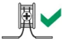

NOTE! Bring the positive (+) wires in on terminal b2 and out from terminal b1. Use a consistent pattern, inputting on b2 and outputting from b1. The negative (-) wires input and output from the same terminal (a1/a2).
3.2.2 EOL Resistors
Use the EOL resistors supplied or specified by the control panel manufacturer. This applies to all loop terminations including the D275 Module and the F220-B6E Power Supervision Base.
3.2.3 Loop Wiring Specifications
In a two-wire system, the maximum loop length depends on the number of F220-B6 bases on the loop, the wire size, and the control panel specifications. Refer to the control panel's installation instructions for specific wiring information.
In a four-wire system, the maximum loop length and number of bases that can be placed on a loop depend on the voltage drop on the power circuit. Use standard voltage drop calculations to ensure that the last detector on the loop meets the minimum voltage requirement of at least 10 V.
3.2.4 Four-wire Loop Termination
One D275 End-of-Line Module (refer to Figure 3.6 on page 17) or F220-B6E Power Supervision Base (refer to Figure 3.4 on page 15) is required for each loop when using four-wire bases.
3.3 Wire Optional Remote Annunciators
If using the optional DRA-5 Remote Alarm Indicator, connect the positive (red) wire to terminal b1 and the negative wire (white) to terminal c (refer to Figure 3.1).

| 1. Red wire to Terminal b1 on base | 2. White wire to Terminal c on base |
Fig.3.1 Optional DRA-5 Remote Annunciator Wiring
3.4 Wire F220-B6 Two-wire Bases
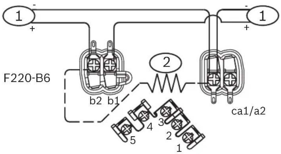
The F220-B6 is a 12 VDC or 24 VDC base for two-wire conventional loops. Refer to Figure 3.2 for wiring details.
-
Initiating device circuit (IDC) input (positive [+] in on terminal b2, out from terminal b1; negative [-] in and out from terminal a1/a2) from the control panel or from a previous two-wire base and output to the next two-wire base.
-
Place the EOL resistor across base's power terminals (b2 and a1/a2) of the last base on the loop. Refer to the control panel installation instructions for resistor specifications.
Fig.3.2 Wiring F220-B6 Two-wire Bases
3.5 Wire F220-B6C/E/R Four-wire Bases

CAUTION! Do not connect relays to inductive or capacitive loads. Use with resistive loads only.
3.5.1 F220-B6C:
The F220-B6C base has a normally open alarm loop relay and auxiliary Form C (NC/C/NO) contacts. The contacts are rated for 0.5 A at 120 VAC/DC for resistive loads. Refer to Figure 3.3 for wiring details.

| 1. Power input (positive [+] in on terminal b2, out from terminal b1; negative [-] in and out from terminal a1/a2) from the control panel or from a previous four-wire base and output to the next four-wire base.2. Initiating device circuit (IDC) input (positive [+] inand out from terminal 5 and negative [-] in and out | from terminal 4) from the control panel or from a previous four-wire base and output to the next four-wire base or to loop termination (refer to Figure 3.4 on page 15 [F220-B6E] or Figure 3.6 on page 17 [D275]).3. Alarm Loop Relay4. Auxiliary Form C Alarm Relay |
Fig.3.3 Wiring F220-B6C Four-wire Bases
3.5.2 F220-B6E:
The F220-B6E Power Supervision Base has a normally-open alarm loop relay that activates when the unit is in alarm and a power supervision relay that activates when power is supplied. Separate power supervision devices, such as the D275, are
unnecessary. Use only one F220-B6E per zone run. It must be the last base on the run. Refer to Figure 3.4 for wiring details.
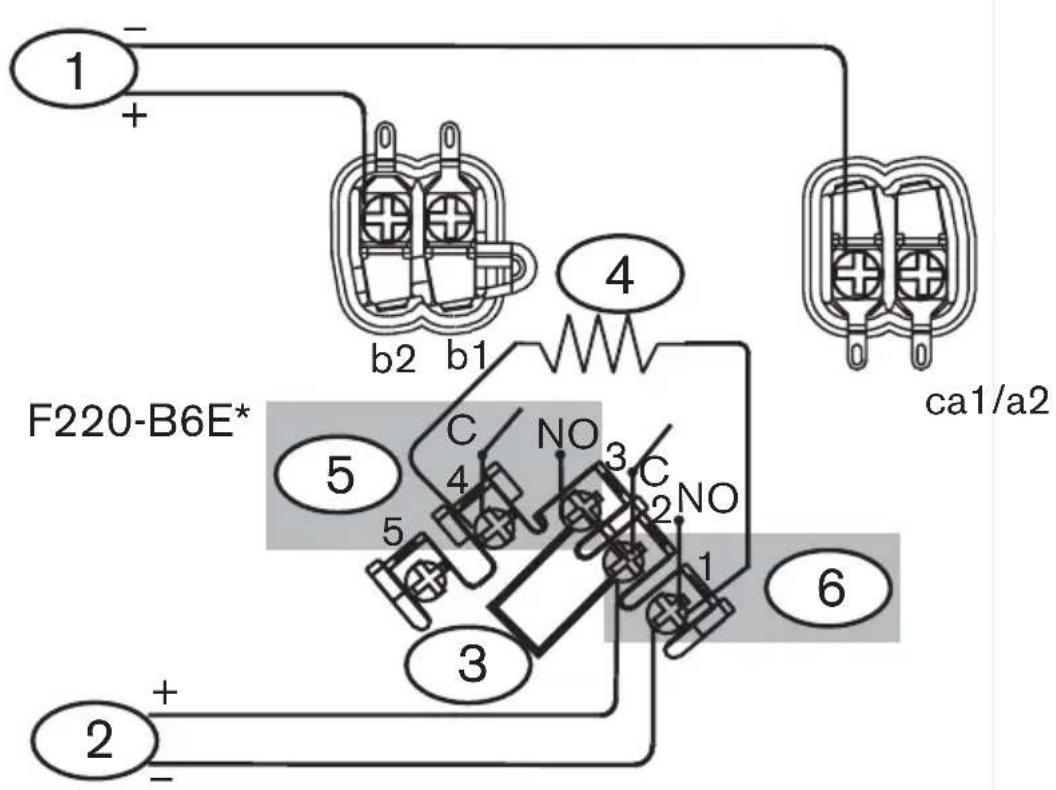
| 1. Power input (positive [+] in on terminal b2; negative [-] in on terminal a1/a2) from the control panel or from a previous four-wire base.2. Initiating device circuit (IDC) input (positive [+] to terminal 2 and negative [-] to terminal 1) from the control panel or from a | previous four-wire base.3. Jumper connecting terminals 2 and 3.4. Place an appropriate EOL resistor (refer to the control panel's installation instructions for resistor specifications) across Terminals 1 and 4.5. Power Supervision Relay6. Alarm Loop Relay |
Fig.3.4 Wiring F220-B6E Four-wire Power Supervision Bases
* F220-B6E Bases can only be used at the end of a loop. The alarm loop relay (Form A, Terminals 1 and 2) and the power supervision relay (Terminal 3 and 4) are rated for 0.5 A at 120 VAC/DC for resistive loads.
3.5.3 F220-B6R:
The F220-B6R is the standard base for four-wire configurations. The Alarm Loop Relay (Terminals 1 and 2) is a normally-open relay rated for 0.5 A at 120 VAC/DC. The relay closes on alarm. Refer to Figure 3.5 for wiring details.
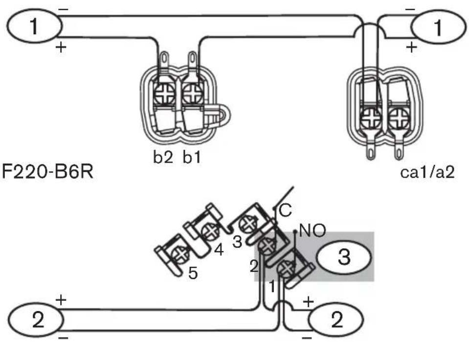
| 1. Resettable auxiliary power input (positive [+] in on terminal b2, out from terminal b1; negative [-] in and out from terminal a1/a2) from the control panel or from a previous four-wire base and output to the next four-wire base.2. Initiating device circuit (IDC) input (positive [+] in and out from terminal 2 | and negative [-] in and out from terminal 1) from the control panel or from a previous four-wire base and output to the next four-wire base or to loop termination (refer to Figure 3.4 on page 15 [F220-B6E] or Figure 3.6 on page 17 [D275]).3. Alarm Loop Relay |
Fig.3.5 Wiring F220-B6R Standard Four-wire Bases
3.6 Wire Power Supervision Modules
3.6.1 Wire F220-B6E Power Supervision Base
Refer to Section 3.5.2 F220-B6E: for F220-B6E wiring instructions.
3.6.2 Wire D275 Power Supervision Module
When a D275 Module (refer to Figure 3.6) is used with 12 VDC systems, connect the red wire to the output terminal (b1) on the last base in the run. The yellow wire remains unconnected. For 24 VDC systems, connect the yellow wire to the output terminal (b1). The red wire remains unconnected.

flowchart
graph TD
    A["1"] --> B["2"]
    B --> C["3"]
    B --> D["2"]
    E["D275"] --> F["+12 VDC"]
    E --> G["+24 VDC"]
    E --> H["Common (-)"]
    I["7"] --> J["4"]
    I --> K["5"]
    I --> L["6"]
| 1. EOL resistor (refer to the control panel's installation instructions for specifications).2. The positive (+) and negative (-) IDC wires (blue) from the D275.3. Connect the positive (+) IDC wire through the EOL resistor to Terminal 2 and the negative (-) IDC wire to Terminal 1 on the last | base on the loop.4. Red wire to Terminal b1 on last base on loop for 12 VDC systems.5. Yellow wire to Terminal b1 on last base on loop for 24 VDC systems.6. Black wire (common) to Terminal a1/a2 on last base on loop.7. Power loop: Use either red or yellow wire; not both. |
Fig. 3.6 Wiring a D275 Power Supervision Module as a Loop Terminator
4 Install the Detector Heads
4.1 Mount the Detector Heads

CAUTION! Before mounting detector heads, all terminal screws in the bases including those not wired must be tightened to prevent loose screw heads from making intermittent electrical contact with the detector head.
4.1.1 Optional Locking Bar
Each base has a snap-off locking bar as part of the base molding. Engage the locking bar to prohibit unauthorized detector removal. To engage the locking bar, move it to the position shown in Figure 4.1. (See also Figure 4.2, Items 4 and 9 on page 19.)

-
Snap locking bar (X) off base molding
-
Insert locking bar (X) into locking bar mount until fully engaged
Fig.4.1 Engaging the Locking Bar

CAUTION! When using the locking bar, before installing the detector head, open the unlocking port (refer to Figure4.2, Item 4) by poking through the plastic with a screwdriver.
4.1.2 Mounting Skirt
Align the four alignment keys (refer to Figure 2.1, Item 11 on page 5 and to Figure 4.2, Item 5) and press the skirt firmly down onto the mounting base (refer to Figure 4.2, Item 3) to engage the snap locks.
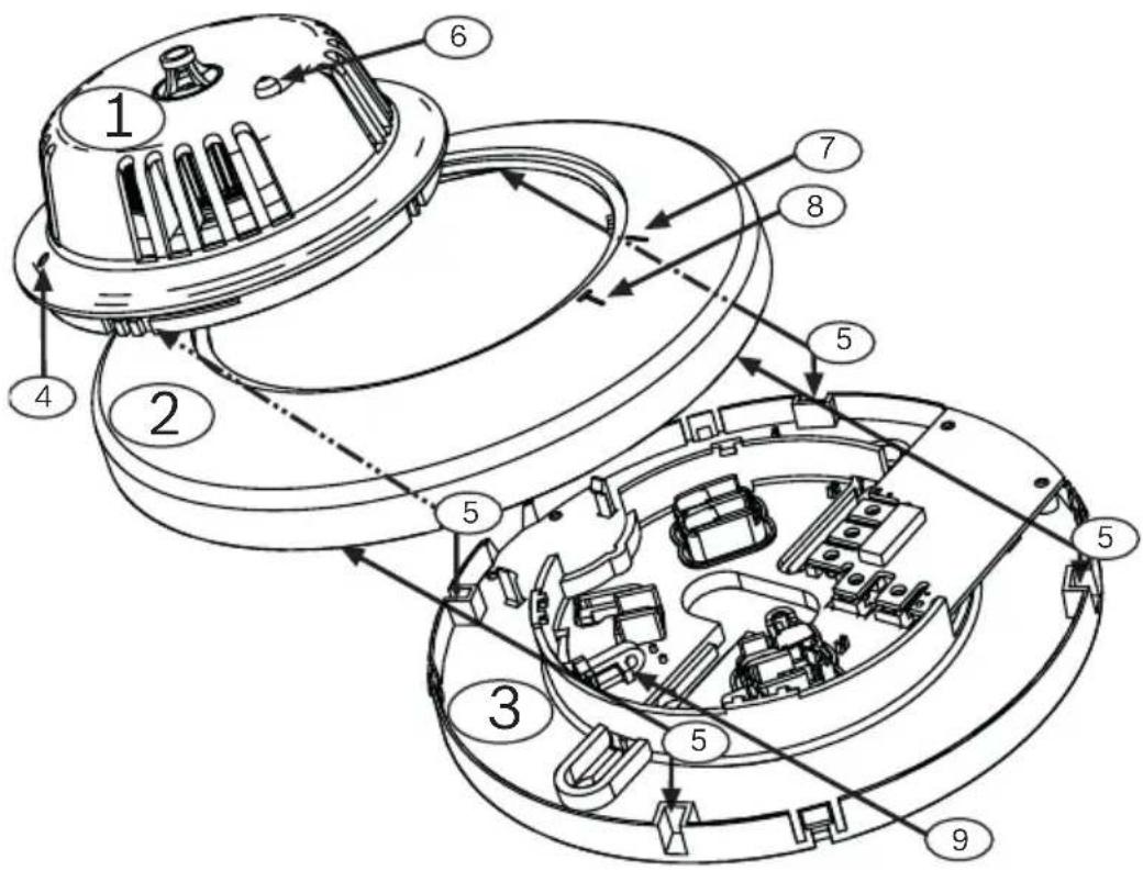
| 1. Detector head (heat detector shown in example)2. Mounting skirt3. Mounting base4. Locking port5. Alignment keys (four places on the bottom of | the mounting skirt and four corresponding places on the base)6. LED7. Bar on mounting skirt8. T mark on mounting skirt9. Locking bar in locked position |
Fig.4.2 Part Orientation for Mounting
4.1.3 Detector Head

CAUTION! The mounting skirts and detector heads are keyed. Do not force them onto the mounting bases.
Install:
Install the detector head by lining up the LED on the detector head (refer to Figure 4.2, Item 6 on page 19) with the bar on the mounting skirt (refer to Figure 4.2, Item 7). Turn the detector head clockwise until the LED aligns with the T mark on the mounting skirt (refer to Figure 4.2, Item 8).
Remove:
Remove the detector head by turning it counter-clockwise. If the optional locking bar is used, refer to Figure 4.3.

-
Insert screwdriver through the locking port and depress the locking bar.
-
Hold the locking bar down while turning the head counter-clockwise until disengaged.
Fig.4.3 Unlocking the Locking Bar
4.2 Set Detector Modes
The F220 Series Smoke Detectors feature a unique magnet-operated sensitivity mode and detector test mode.
4.2.1 Test Mode
Test the detector by placing the magnet next to the T mark on the mounting skirt (refer to Figure 4.2, Item 8 on page 19) for three consecutive flashes to cause an alarm.
4.2.2 Sensitivity Mode
If the magnet is next to the T mark for less than three flashes but more than one flash, the detector enters Sensitivity Mode.
- Place the detector into Sensitivity Mode.
- Wait for the first single green LED flash.
- Count the number of red LED flashes that follow and refer to Table4.1 for sensitivity definitions.
| Number of Red Flashes | Sensitivity Definition (% Obscuration) |
| 1 Malfunctioning smoke or heat detector | |
| 3 Normally operating smoke or heat detector with little or no dirt contamination | |
| 4 to 6 Progressively more contamination | |
| 7 to 10 Trouble condition, very dirty but still compensated to 3%/ft (3%/ft = 0.433 db/m); Sensitivity < 3%/ft at 10 flashes. | |
| 11 Sensitivity < 2.5%/ft (2.5%/ft = 0.36 db/m) | |
| 12 Sensitivity < 2.0%/ft (2.0%/ft = 0.287 db/m), chance of false alarm increases | |
| 13 Sensitivity < 1.5%/ft (1.5%/ft = 0.214 db/m) | |
| 14 Sensitivity < 1.0%/ft (1.0%/ft = 0.143 db/m), chance of false alarm greatly increases | |
| 15 Sensitivity < 0.5%/ft (0.5%/ft = 0.071 db/m), false alarm likely | |
Table 4.1 Red LED Flash Definition
- The detector exits sensitivity mode and returns to one green LED flash every eight seconds.
4.3 Set CleanMe Feature
The Clean Me feature monitors the smoke chamber's sensitivity and sends a trouble signal to the control panel when the sensitivity degrades to a preset level.

NOTE! When a CleanMe signal is sent to a control panel that is not CleanMe compatible, the signal may be misinterpreted as an alarm.
To activate the CleanMe feature:
- Put the detector into sensitivity mode by placing a magnet next to the T mark on the mounting skirt (refer to Figure 4.2, Item 8 on page 19). Remove the magnet after the first red LED flash and before the third red LED flash.
- When the magnet is removed, the LED flashes green once and shows the first of two sensitivity displays.
- When the LED next flashes red, replace the magnet near the T mark (refer to Figure 4.2, Item 8 on page 19).
- Hold the magnet against the T mark on the mounting skirt (refer to Figure 4.2, Item 8 on page 19) until the green LED flashes twice and the red LED repeats the sensitivity indication.
- The detector exits sensitivity mode. If CleanMe has been successfully enabled, the green LED flashes twice in rapid succession every eight seconds indicating that CleanMe is activated.
To disable CleanMe, repeat this process and verify the double flash returns to a single flash.
4.4 Flash Rate and Trouble Indication
These detectors include the Chamber Check Automatic Trouble Indicator that verifies the detector's calibration is within the factory listed range. NFPA guidelines for sensitivity testing can be met by visually inspecting the detector and checking the flash rate of the LED.

NOTE! Perform the visual check before resetting power. After a reset the trouble indicators clear for 70 seconds. After 70 seconds, if the detector is in a trouble condition, trouble indications begin again.
A unit with CleanMe activated double flashes (two flashes within a half second of each other) every eight seconds. A normally operating unit flashes once every eight seconds. If a detector is in a trouble condition due to a dirty lens or a sensor malfunction, it single or double flashes every four seconds. If enabled, the CleanMe trouble signal is sent.
5 Test the Installation
5.1 Inspect the Installation
- Check the wiring from the control panel to the last head on each run for proper polarity and continuity.
- Terminate each run with an EOL resistor as specified by the control panel manufacturer.
- Terminate four-wire runs with EOL power supervision modules or F220-B6E bases.
- Apply power to the system. Check for alarms and troubles.
- Note which detectors alarmed (if any), shut down the system, remove alarmed detectors from their bases, and recheck the bases for proper wiring.
- If the problem persists, determine if the problem is caused by the detector or the base. Replace the affected detectors or bases with known good units.
- If a system alarm occurs with no detector alarms present, remove all detectors and check the wiring at each base.
- Check the wiring of each EOL resistor and EOL module.
- When the system is alarm free, check each detector to ensure that the green LED indicator flashes approximately
every eight seconds. This verifies the detector is receiving power and operating properly.

NOTE! If a heat detector LED flashes at a rate of 4 flashes/sec, the detector is either cold (below +32°F [0°C]), out of sensitivity range, or defective. If a smoke detector flashes at a rate of 4 flashes/sec, it is either out of sensitivity range or defective.
5.2 Test Each Detector
Test each detector to ensure it causes a control panel alarm.
Reset the control panel after each test.
5.2.1 Activate an Alarm at Each Detector
To cause heat detectors to alarm either:
- Activate the internal reed switch by placing a magnet horizontally against the T mark on the mounting skirt (refer to Figure 4.2, Item 8 on page 19) and holding it there for three consecutive LED flashes, or
- Expose the thermistor (refer to Figure 2.2, Item 3 on page 7) to a heat source such as a hair dryer or a shielded heat lamp until the detector alarms and the alarm LED lights.
To cause smoke detectors to alarm either:
- Activate the internal reed switch by placing a magnet horizontally against the T mark on the mounting skirt (refer to Figure 4.2, Item 8 on page 19) and holding it there for three consecutive LED flashes, or
- Use a UL Listed aerosol smoke detector tester to simulate an alarm. Follow the instructions provided with the aerosol smoke detector tester.
5.2.2 Reset the Control Panel
When a detector alarms, the red LED indicator activates and latches into the ON position. Clear the alarm by momentarily removing power before proceeding to the next detector.
5.3 Test the Alarm Loop
Checkthe voltage across the EOL resistor of each alarm loop to verify wiring losses do not exceed control panel manufacturer's specifications.
5.4 Test CO Sensors
Removing the detector head or resetting the detector's power places the detector in a special test mode for 15 minutes. If over 35 ppm of CO is applied to the detector within this 15-minute period, the detector must alarm or it is defective.

WARNING! The F220-PTHC detects carbon monoxide (CO) as a component of a fire. Do not use the F220-PTHC as a stand-alone CO detector.
5.5 Perform NFPA 72 Required Testing
Refer to Section 1.2 Required Maintenance and Testing on page 2.
Bosch Security Systems, Inc.
130 Perinton Parkway
Fairport, NY 14450-9199
USA
Customer Service: (800) 289-0096
Technical Support: (888) 886-6189
www.boschsecurity.us
© Bosch Security Systems, Inc., 2007


- F220 Series Detectors with F220-B6/C/E/R Bases
- L e g a l
- Trademarks
- Required Maintenance and Testing
- General Information
- F220-B6 Series Detector Bases
- Compatible Control Panels
- Base Comparisons
- Base Features
- F220 Series Detectors
- About F220 Series Detector Heads
- F220 Series Detector Features
- F220 Series Heat Detector Heads
- F220 Series Smoke Detector Heads
- Technical Specifications
- General Specifications
- Base Specifications
- Detector Specifications
- Electrical Supervision
- Install the Bases
- Mount the Bases
- Wire the Bases
- Terminal Connections
- EOL Resistors
- Loop Wiring Specifications
- Four-wire Loop Termination
- Wire Optional Remote Annunciators
- Wire F220-B6 Two-wire Bases
- Wire F220-B6C/E/R Four-wire Bases
- F220-B6C:
- F220-B6E:
- F220-B6R:
- Wire Power Supervision Modules
- Wire F220-B6E Power Supervision Base
- Wire D275 Power Supervision Module
- Install the Detector Heads
- Mount the Detector Heads
- Optional Locking Bar
- Mounting Skirt
- Detector Head
- Install:
- Remove:
- Set Detector Modes
- Test Mode
- Sensitivity Mode
- Set CleanMe Feature
- Flash Rate and Trouble Indication
- Test the Installation
- Inspect the Installation
- Test Each Detector
- Activate an Alarm at Each Detector
- To cause heat detectors to alarm either:
- To cause smoke detectors to alarm either:
- Reset the Control Panel
- Test the Alarm Loop
- Test CO Sensors
- Perform NFPA 72 Required Testing
Brand : BOSCH
Model : F220-B6C
Category : Detector