
DAG 230D - Grinder HILTI - Free user manual and instructions
Find the device manual for free DAG 230D HILTI in PDF.
| Product Type | Angle Grinder (grinder) |
| Brand | Hilti |
| Model | DAG 230D |
| Dimensions (L x W x H) | 510 x 138 x 111 mm |
| Weight | 5.9 kg (according to EPTA 01/2003) |
| Power Supply | 230 V, 10 A, 50/60 Hz, 2,200 W |
| No-load Speed | 6,500 /min |
| Max. Wheel Diameter | 230 mm |
| Max. Wheel Thickness | 8 mm |
| Spindle Thread | M14 |
| Spindle Length | 25 mm |
| Protection Class | Class II (double insulation) |
| Main Functions | Cutting, grinding, grooving (metals and minerals) |
| Safety | ATC (Anti-Kickback), anti-restart protection, adjustable guard, side handle |
| Maintenance and Cleaning | Clean ventilation slots with a dry brush; wipe the exterior with a damp cloth; regularly check brushes and cables |
| Spare Parts and Repairability | Spare parts available from Hilti service; repair by qualified personnel only |
| Manufacturer Warranty | Warranty against manufacturing defects, wear parts excluded |
Frequently Asked Questions - DAG 230D HILTI
User questions about DAG 230D HILTI
0 question about this device. Answer the ones you know or ask your own.
Ask a new question about this device
Download the instructions for your Grinder in PDF format for free! Find your manual DAG 230D - HILTI and take your electronic device back in hand. On this page are published all the documents necessary for the use of your device. DAG 230D by HILTI.
USER MANUAL DAG 230D HILTI
2.6 ATC (Active Torque Control)
Head of BA Quality and Process Mana
gement
Business Area Electric Tools & Acces
sories
01/2012
Jan Doongaji
Executive Vice President
It is essential that the operating instruct are read before the power tool is open the first time.
Always keep these operating instructions gather with the power tool.
Ensure that the operating instructions a with the power tool when it is given persons.
Contents Page
1 General information 16
2 Description 17
3 Consumables 19
4 Technical data 20
5 Safety instructions 21
6 Beforeuse 25
7Operation 26
8 Care and maintenance
9 Troubleshooting 28
0 Disposal 29
1 Manufacturer's warranty - tools
2 EC declaration of conformity (original)
- These numbers refer to the corresponding illustrations. The illustrations can be found on the fold-out covers
pages. for keep these pages open while studying, eating instructions.
In these operating instructions, the designation "the power tool" always refers to the DCG 230-D or DAG 230-D angle grinder.
e Parts operating controls and indicators 1 to other
① Clamping nut
② "Kwik-Lock" clamping nut (optional)
③ Cutting disc
④ Clamping flange
⑤ Keying lug
Guard
⑦ Spindle
Adjusting screw
⑨ Clamping lever
10 Steadying rib
2g11 Threaded bushing for grip
12 Drive spindle lockbutton
(3) Release lever (for pivotable grip)
24) Side handle
On / off switch (hold to run)
16 Wrench
1 General information
1.1 Safety notices and their meaning
DANGER
Draws attention to imminent danger that will lead to serious bodily injury or fatality.
WARNING
Draws attention to a potentially dangerous situation could lead to serious personal injury or fatality.
CAUTION
Draws attention to a potentially dangerous situation could lead to slight personal injury or damage to the equipment or other property.
NOTE
Draws attention to an instruction or other useful information.
1.2 Explanation of the pictograms and other information
Warning signs

General warning
Warning: electricity
on that
Obligation signs

Wear eye protection

Wear a hard hat

Wear ear protection

Wear protective gloves

Wear breathing protection
Symbols

Read the operating instructions before use

Return waste material for recycling.

Volts Amps


Rated speed
current

Revolutions per minute

Revolutions per minute

Diameter

Double insulated
2 Description
2.1 Use of the product as directed
The power tool is designed for cutting and grinding metal and mineral materials without use of water.
Observe the information printed in the operating instructions concerning operation, care and maintenance.
Working with metals: Cutting, grinding.
Working with mineral materials: Cutting, slitting and grinding.
Use only discs (grinding discs, cutting discs, etc.) approved for use at a speed of at least 6500/min., with a thickness of max. 8 mm and a diameter of max. 230 mm.
Use only synthetic resin-bonded, fiber-reinforced grinding discs or cutting discs approved for use at a permissible peripheral speed of at least 80 m/sec.
To avoid the risk of injury, use only genuine Hitti accessories and insert tools.
Working on materials hazardous to the health (e.g. asbestos) is not permissible.
Nationally applicable industrial safety regulations must be observed.
Modification of the power tool or tampering with its parts is not permissible.
The power tool may be operated only when connected to a power supply providing a voltage and frequency in compliance with the information given on its type identification plate.
The working environment may be as follows: construction site, workshop, renovation, conversion or new construction.
Location of identification data on the power tool
The type designation and serial number can be found on the type identification plate on the machine or to Make a note of this data in your operating and always refer to it when making an enquiry to Hilti representative or service department.
Type:
Generation: 01
Serial no.:
The power tool is designed for professional use and may be operated, serviced and maintained only by trained, authorized personnel. This personnel must be informed of any special hazards that may be encountered. The power tool and its ancillary equipment may present hazards when used incorrectly by untrained personnel when used as directed.
Take the influences of the surrounding area into account. Do not use the power tool or appliance where there is a risk of fire or explosion.
en
2.2 Grips
Vibration-absorbing grip
Pivotable hoop grip
2.3 Switches
On / off switch (hold to run)
2.4 Items supplied as standard include:
1 Power tool
1 Gu a r d
1 S i d e h a n d l e
1 Clamping flange
1 C l a m p i n g n u t
1 "Kwik-Lock" clamping nut (optional)
1 W r e n c h
1 Operating instructions
2.5 Starting current limitation
The electronic starting current limiter reduces the starting current drawn by the power tool and thus prevents the mainsfuseblowing.Italsoallowsthepowertooltostartsmoohly,withouta jolt.
2.6 ATC (Active Torque Control)
The electronics in the power tool detect situations where there is a risk of the disc sticking and prevent further rotation of the drive spindle by switching the power tool off (does not prevent kickback). The switch must be released and pressed again to restart the power tool.
NOTE
In the event of a fault in the ATC system, the power tool will continue to run but at greatly reduced speed and with lower torque. The power tool must be returned to Hitti Service for servicing.
2.7 Restart interlock
The power tool does not restart by itself when the switch remains pressed and the power returns in the electric supply. The switch must first be released and then pressed again to restart.
2.8 Using extension cords
Use only extension cords of a type approved for the application and with conductors of adequate cross power tool may otherwise loose performance and the extension cord may overheat. Check the extension cord for damage at regular intervals. Replace damaged extension cords.
Recommended minimum conductor cross section and max. cord lengths
| Conductor cross section | 1.5 mm² 2 mm² | 2.5 mm² 3.5 | mm² | |
| Mains voltage 100V 30 | m | 50 | m | |
| Mains voltage 110-127 V | 20 m | 30 m | 40 m | 50 m |
| Mains voltage 220-240 V | 50 m | 100 m |
Do not use extension cords with 1.25 mm² conductor cross section.
2.9 Using extension cords outdoors
When working outdoors, use only extension cords that are approved and correspondingly marked for this application.
2.10 Using a generator or transformer
This power tool may be powered by a generator or transformer when the following conditions are fulfilled: The unit must provide a power output in watts of at least twice the value printed on the type identification plate on the power tool. The operating voltage must remain within +5% and -15% of the rated voltage at all times, frequency must be in the 50 - 60 Hz range and never above 65 Hz, and the unit must be equipped with automatic voltage regulation and starting boost.
Never operate other power tools or appliances from the generator or transformer at the same time. Switching other power tools or appliances on and off may cause undervoltage and / or overvoltage peaks, resulting in damage to the power tool.
2.11 DC-EX 230/9" disc guard with guide carriage for cutting 2
The power tool may be used for cutting work on mineral materials only when fitted with a disc guard (dust removal hood) and guide carriage.
CAUTION
Use of this guard for working on metal is not permissible.
NOTE
It is recommended that a dust removal system consisting of matched components, i.e. dust removal hood and a suitable Hilti vacuum cleaner, are used for cutting and slitting mineral materials, such as concrete or stone. This system serves to protect the operator and increase the life of the power tool and disc used.
2.12 Guard with cover plate 3
CAUTION
When grinding with straight grinding discs and cutting with cutting discs in metalworking applications, use the guard with cover plate.
3 Consumables
Discs of max. 230 mm diameter, a rotational speed of 6500/min, a peripheral speed of 80 m/sec and max. 8 mm disc thickness.
| Discs Application Designation | Material | ||
| Abrasive cutting disc Cutting,slitting AC-D metalDiamond cutting disc Cutting,slitting DC-D mineralAbrasive grinding disc Rough grinding AG-D | slitting AC-D metal | ||
| slitting DC-D mineral | |||
| metal |
Assignment of discs to the equipment used
| Item | Equipment | AC-D | AG-D | DC-D |
| A | Guard | - | X | X |
| B | Guard with cover plate | X | - | X |
| C | DC-EX 230/9" cutting guard | - | - | X |
| D | Side handle | X | X | X |
| E | DC BG hoop-handle (optional for D) | X | X | X |
| F | Clamping nut | X | X | X |
| G | Clamping flange | X | X | X |
| H | Kwick-Lock (optional for F) | X | X | X |
4 Technical data
Right of technical changes reserved.
| Power tool | DCG 230-D | DAG 230-D | |
| Rated current / power input | Rated voltage 230 V: 12.0 A / 2,600 W (CH 2200 W/10 A) | Rated voltage 230 V: 10.0 A | |
| Rated voltage 110 V: 20 A / 2,200 W | Rated voltage 110 V: 19.4 A | ||
| Rated voltage 127 V: 15 A | 2,000 W | ||
| Rated frequency 50/60 Hz 50/60 Hz | |||
| Rated speed 6,500/min 6,500/min | |||
| Max. washer diameter Diameter | 230 mm Diameter 230 mm | ||
| Dimensions (L x H x W) with hood | 0.525 mm x 138 mm x 111 mm | 510 mm x 138 mm x 11 | |
| Weight in accordance with EPT procedure 01/2003 | A6.6 kg 5.9 kg | ||
Information about the power tool and its applications
| Drive spindle thread (arbor size) | M 14 |
| Spindle length | 25 mm |
| Protection class as per EN / IEC | Protection class II (double insulated) |
NOTE
The vibration emission level given in this information sheet has been measured in accordance with a standardised test given in EN 60745 and may be used to compare one tool with another. It may be used for a preliminary assessment of exposure. The declared vibration emission level represents the main applications of the tool. However if the tool is used for different applications, with different accessories or poorly maintained, the vibration emission may differ. This may significantly increase the exposure level over the total working period. An estimation of the level of exposure to vibration should also take into account the times when the tool is switched off or when it is running but not actually doing the job. This may significantly reduce the exposure level over the total working period. Identify additional safety measures to protect the operator from the effects of vibration such as: maintain the tool and the accessories, keep the hands warm, organisation of work patterns.
Noise information (as perEN 60745-1):
| Typical A-weighted sound power level, DCG 230 | 101 dB (A) | |||
| Typical A-weighted emission sound pressure level,90 dB (A) | ||||
| DCG 230 | ||||
| Typical A-weighted sound power level, DAG 230 | 101 dB (A) | |||
| Typical A-weighted emission sound pressure level,90 dB (A) | ||||
| DAG 230 | ||||
| Uncertainty for the given sound level | 3 dB (A) | |||
Vibration information in accordance with EN 60745-1
| Triaxial vibration values (vibration vector sums) fonea#ed in accordance with EN 60745-2-3 DCG 230-D | |
| Surface grinding with the vibration absorbing sid6.5 m/s2 handle, #AG | |
| Uncertainty (K) | 1.5 m/s2 |
| Triaxial vibration values (vibration vector sums) fonea#ed in accordance with EN 60745-2-3 DAG 230-D | |
| Surface grinding with the vibration absorbing sid6.0 m/s2 handle, #AG | |
5 Safety instructions
5.1 General Power Tool SafetyWarnings
a)

WARNING
Read all safety warnings and all instruction to follow the warnings and instructions in electric shock, fire and/or serious injury. warnings and instructions for future referer The term "power tool" in the warnings refers your mains-operated (corded) power tool or operated (cordless) power tool.
5.1.1 Workareasafety
a) Keep work area clean and well lit. Clutter areas invite accidents.
b) Do not operate power tools in explosive spheres, such as in the presence of flame liquids, gases or dust. Power tools create which may ignite the dust or fumes.
c) Keep children and bystanders away while ing a power tool. Distractions can cause y control.
5.1.2 Electrical safety
a) Power tool plugs must match the outlet. modify the plug in any way. Do not use apter plugs with earthed (grounded) power Unmodified plugs and matching outlets will risk of electric shock.
b) Avoid body contact with earthed or ground surfaces, such as pipes, radiators, ranges refrigerators. There is an increased risk of shock if your body is earthed or grounded.
c) Do not expose power tools to rain or w tions. Water entering a power tool will incre risk of electric shock.
d) Do not abuse the cord. Never use the carrying, pulling or unplugging the power. Keep cord away from heat, oil, sharp ed moving parts. Damaged or entangled cords since the risk of electric shock.
e) When operating a power tool outdoors, use extension cord suitable for outdoor use. Use a cord suitable for outdoor use reduces the electric shock.
f) If operating a power tool in a damp load unavoidable, use a residual current device protected supply. Use of an RCD reduces of electric shock.
5.1.3 Personal safety
(a) Stay alert, watch what you are doing and use common sense when operating a power tool. Do not use a power tool while you are tired.
the influence of drugs, alcohol or medical moment of inattention while operating power may result in serious personal injury.
ns) use personal protective equipment. Always wear may eyesup protection. Protective equipment such as dust Save mask, non-skid safety shoes, hard hat, or hearing ice. protectionusedforappropriate conditionswillreduce s to personal injuries.
battery Prevent unintentional starting. Ensure the switch is in the off-position before connecting to power source and/or battery pack, picking up or carrying the tool. Carrying power tools with your finger or switch or energising power tools that have the s on invites accidents.
d) Remove any adjusting key or wrench before tu atmoing the power tool on. A wrench or a key left mable tached to a rotating part of the power tool may sparks in personal injury.
e) Do not overreach. Keep proper footing and bal operat- ance at all times. This enables better control of ou to lose tool in unexpected situations.
f) Dress properly. Do not wear loose clothing or jewellery. Keep your hair, clothing and gloves away from moving parts. Loose clothes, jewellery or long hair can be caught in moving parts.
any devices are provided for the connection of c extraction and collection facilities, ensure these are connected and properly used. Use of dust collection can reduce dust-related hazards.
and1.4 Power tool use and care electric
(a) Do not force the power tool. Use the correct power tool for your application. The correct power tool will do the job better and safer at the rate I use the which it was designed.
b) Do not use the power tool if the switch does not turn it on and off. Any power tool that cannot be controlled with the switch is dangerous and must be repaired.
Case (c) Disconnect the plug from the power source and/or the battery pack from the power tool. Use an before making any adjustments, changing use of accessories, or storing power tools. Such a preventive safety measures reduce the risk of starting the power tool accidentally.
Store idle power tools out of the reach of children and do not allow persons unfamiliar with power tool or these instructions to operate the power tool. Power tools are dangerous in the hand of untrained users.
e) Maintain power tools. Check for misalignment or use binding of moving parts, breakage of parts and vol. Do any other condition that may affect the power or under
tool's operation. If damaged, have the power toolload speed for one minute. Damaged
repaired before use. Many accidents are caused abcessories will normally break apart during this test poorly maintained power tools.
f) Keep cutting tools sharp and clean. Prope tained cutting tools with sharp cutting edges likely to bind and are easier to control.
g) Use the power tool, accessories and tool in accordance with these instructions, taking account the working conditions and the work be performed. Use of the power tool for tations different from those intended could result in hazardous situation.
5.1.5 Service
a) Haveyourpowertool servicedbya qualifiedrepair person using only identical replacement pa This will ensure that the safety of the pow maintained.
5.2 Safety warnings for abrasive cutting-off operations
a) This power tool is intended to function as off tool. Read all safety warnings, instruct illustrations and specifications provided with power tool. Failure to follow all instructions below may result in electric shock, fire and injury.
b) Operations such as sanding, wire brushing polishing are not recommended to be per with this power tool Operations for which tool was not designed may create a hazard personal injury.
c) Do not use accessories which are not sp designed and recommended by the tool n turer. Just because the accessory can be a to your power tool, it does not assure saf
d) The rated speed of the accessory must least equal to the maximum speed mark power tool. Accessories running faster than rated speed can break and fly apart.
e) The outside diameter and the thickness of accessory must be within the capacity rat your power tool. Incorrectly sized accessories not be adequately guarded or controlled.
f) Threaded mounting of accessories must ma the grinder spindle thread. For accessories ted by flanges, the arbour hole of the a must fit the locating diameter of the flanc ccessories that do not match the mounting of the power tool will run out of balance, excessively and may cause loss of control.
g) Do not use a damaged accessory. Before use inspect the accessory such as abrasive wheels for chips and cracks, backing pad cracks, tear or excess wear, wire brush or cracked wires. If power tool or accessory is dropped, inspect for damage or install undamaged accessory. After inspecting and installing an accessory, position yourself and bystanders away from the plane of the accessory and run the power tool at max
lyh) mWear personal protective equipment. Depending are onessapplication, use face shield, safety goggles safety glasses. As appropriate, wear dust mask, bits hearing protectors, gloves and workshop apron ing intapable of stopping small abrasive or workpiece work fragments. The eye protection must be capable of operastopping flying debris generated by various operat-. ult intions. The dust mask or respirator must be capable filtrating particles generated by your operation. Prolonged exposure to high intensity noise may cause hearing loss.
i) Keep bystanders a safe distance away from work area. Anyone entering the work area must wear personal protective equipment. Fragments of workpiece or of a broken accessory may fly away and cause injury beyond immediate area of operation.
j) Hold the power tool by insulated grippingsurface only, when performing an operation where the is a cutting accessory may contact hidden wiring or ions, its own cord. Cutting accessory contacting a "live this wire may make exposedmetalparts of the power to listed live" and could give the operator an electric sho ork position the cord clear of the spinning accessory If you lose control, the cord may be cut or sn or and your hand or arm may be pulled into the spinning formed accessory.
the power tool down until the access and cause come to a complete stop. The spinning accessory may grab the surface and pull the power out of your control.
handfado not run the power tool while carrying it at attached side. Accidental contact with the spinning accessory, the operation could snag your clothing, pulling the accessory into be at your body.
n Regularly clean the power tool's air vents. The motor's fan will draw the dust inside the housing and excessive accumulation of powdered metal may cause electrical hazards.
ing do not operate the power tool near flammable can materials. Sparks could ignite these materials.
p) Do not use accessories that require liquid
tch coolants. Using water or other liquid coolants may
moun result in electrocution or shock.
accessory
Accessory
ge. Ac
hardware
Kickback is a sudden reaction to a pinched or snag
rotating wheel, backing pad, brush or any other acc
each Pinching or snagging causes rapid stalling of the
rotating accessory which in turn causes the uncontrolled
power tool to be forced in the direction opposite of
acceasery's rotation at the point of the binding.
For example, if an abrasive wheel is snagged or pin any the workpiece, the edge of the wheel that is en into the pinch point can dig into the surface of the dcausing the wheel to climb out or kick out. The wr atting jump toward or away from the operator, depel kinumdirection of the wheel's movement at the point o
pinching. Abrasive wheels may also break under conditions.
Kickback is the result of power tool misuse and correct operating procedures or conditions and avoided by taking proper precautions as given
a) Maintain a firm grip on the power tool position your body and arm to allow you to kickback forces. Always use auxiliary hand provided, for maximum control over kickback torque reaction during start-up. The operator control torque reactions or kickback forces, in precautions are taken.
b) Never place your hand near the rotating pory. Accessory may kickback over your hand
c) Do not position your body intheareawherep tool will move if kickback occurs. Kickback propel the tool in direction opposite to the movement at the point of snagging.
d) Use special care when working corners, edges etc. Avoid bouncing and snagging to cessory. Corners, sharp edges or bouncing tendency to snag the rotating accessory and loss of control or kickback.
e) Do not attach a saw chain woodcarving toothed saw blade. Such blades create free kickback and loss of control.
5.4 Safety warnings specific for grinding and abrasive cutting-off operations
a) Use only wheel types that are recommend your power tool and the specific guard o for the selected wheel. Wheels for which tool was not designed cannot be adequately and are unsafe.
b) The grinding surface of centre depressed must be mounted below the plane of the An improperly mounted wheel that projects to the plane of the guard lip cannot be added protected.
c) The guard mustbesecurely attachedtothepow tool and positioned for maximum safety, s least amount of wheel is exposed towards erator. The guard helps to protect operator broken wheel fragments, accidental contact with wheel and sparks that could ignite clothing.
d) Wheels must be used only for recommendations. For example: do not grind with of cut-off wheel. Abrasive cut-off wheels are ded for peripheral grinding, side forces appl these wheels may cause them to shatter.
e) Always use undamaged wheel flanges that correct size and shape for your selected Proper wheel flanges support the wheel thus cing the possibility of wheel breakage. Flang cut-off wheels may be different from grinding flanges.
f) Do not use worn down wheels from large tools. Wheel intended for larger power tools suitable for the higher speed of a smaller may burst.
Additional safety warnings specific for abrasive cutting-off operations
d/ or d) do not "jam" the cut-off wheel or apply excess pressure. Do not attempt to make an excessive depth of cut. Overstressing the wheel increases the loading and susceptibility to twisting or binding of the wheel in the cut and the possibility of kickb
e, b) if Do not position your body in line with a enck or the rotating wheel. When the wheel, at the point can of operation, is moving away from your body, the proper kickback may propel the spinning wheel and the power tool directly at you.
access
c) When wheel is binding or when interrupting a power tool, switch off the power tool and the power tool motionless until the wheel comes to a complete stop. Never attempt to remove cut-off wheel from the cut while the wheel is motion otherwise kickback may occur. Investigate and take corrective action to eliminate the cause of the wheel binding.
nae do not restart the cutting operation in the wo cause piece. Let the wheel reach full speed and car re-enter the cut. The wheel may bind, walk up blade or kickback if the power tool is restarted in the wo uent piece.
e) Support panels or any oversized workpiece to minimize the risk of wheel pinching and kickba Large workpieces tend to sag under their own weight.
Supports must be placed under the workpiece near the line of cut and near the edge of the workpiece.
the power extra caution when making a "pocket cut" guaranteed existing walls or other blind areas. The pr truding wheel may cut gas or water pipes, electri wheelsiring or objects that can cause kickback. guard lip.
through Additional safety instructions 5.6.1 Personal safety
a) Always hold the power tool securely with both to th bands on the grips provided. Keep the grips c theclean and free from oil and grease.
Breathing protection must be worn if the powe th tool is used without a dust removal system fo work that creates dust.
I need to improve the blood circulation in your fingers by the relaxing your hands and exercising your fingers. Introducing breaks between working.
ed) to Avoid touching rotating parts. Switch the power tool on only after bringing it into position at are workpiece. Touching rotating parts, especially rotatwheeling insert tools, may lead to injury.
eduAlways lead the supply cord and extension cords away from the power tool to the rear while using this helps to avoid tripping over the cord working.
erf) powhen grinding with straight grinding discs and is no cutting with cutting discs in metalworking applicc tool axions, use the guard with cover plate.
g) Do not use the power tool if it starts with a jolt. This may be an indication that the electronic coil is defective. Have the tool repaired at an Hilti service center right away.
h) Children must be instructed not to play power tool.
i) The power tool is not intended for use by debilitated persons or those who have no instruction or training.
j) Dust from material such as paint containing some wood species, minerals and metal may harmful. Contact with or inhalation of the cause allergic reactions and/or respiratory dis to the operator or bystanders. Certain kinds are classified as carcinogenic such as oak a dust especially in conjunction with additives conditioning (chromate, wood preservative). May containing asbestos must only be treated by ists. Where the use of a dust extraction possible it shall be used. To achieve a of dust collection, use a suitable vacuum of the type recommended by Hilti for wood and/or mineral dust together with this tool that the workplace is well ventilated. The dust mask of filter class P2 is recommend low national requirements for the materials want to work with.
5.6.2 Power tool use and care
a) Grinding discs must be stored and handle fully in accordance with the manufacturer's.
strictions.
b) Check that the grinding disc is fitted in ance with the manufacturer's instructions.
c) If use of a spacer ring or other interme specifiedand the part is supplied with the disc, check to ensure that the part is fit
d) Never use the power tool without the gun.
e) The workpiece must be fixed securely in
f) Before use, check that the cutting disc has fitted correctly and the clamping nut tight. Then allow the power tool to run for 60 s under no load while holding it securely. If the power tool immediately if significant was or any other faults are noticed. Should the examine the power tool in order to determine cause.
g) Do not use cutting discs for grinding.
h) Take steps to ensure that flying sparks power tool do not present a hazard, i.e. yourself or other persons. Adjust the position the guard accordingly.
i) After disc breakage, or if the power tool dropped, falls or suffers other mechanical damage, it must be checked at a Hilti Center.
5.6.3 Electrical safety
htrol unit
authorized

by children, a) Before beginning work, check the working area (e.g. using a metal detector) to ensure that no concealed electric cables or gas and water pipes lead, are present. External metal parts of the power supply may become live, for example, when an electric compressor must be damaged accidentally. This presents a serious risk for severe cases of electric shock.
For wood clust if found to be damaged. If the power is special supply cord is damaged it must be replaced with a specially-prepared supply cord available from device Hilt Customer Service. Check extension cords at regular intervals and replace them if found to be damaged. Do not touch the supply cord or load dust extension cord if it is damaged while working. Ensure Disconnect the supply cord plug from the power use outlet. Damaged supply cords or extension cords present a risk of electric shock.
c) Dirty or dusty power tools which have been used frequently for work on conductive materials should be checked at regular intervals at a Hi Service Center. Under unfavorable circumstances, dampness or dust adhering to the surface of in- the power tool, especially dust from conductive materials, may present a risk of electric shock.
When working outdoors with an electric tool check to ensure that the tool is connected to a diate electric supply by way of a ground fault circuit, grindingupter (RCD) with a rating of max. 30mA fitted. (tripping current). Use of a ground fault circuit card. interrupter reduces the risk of electric shock.
place use of a ground fault circuit interrupter (RCD as beendual current device) with a maximum tripping ened.current of 30 mA is recommended. seconds
swth4 offwork area
ribation ensure that the workplace is well lit.
his) ensure that the workplace is well ventilated. Ex- mine posure to dust at a poorly ventilated workplace n result in damage to the health.
c) If the work involves breaking right through, take from the appropriate safety measures at the opposite by striking parts breaking away could fall out and / or tion down and injure other persons.
d) Slits cut in loadbearing walls of buildings or other structures may influence the statics of the structure, especially when steel reinforcing bars or load-bearing service components are cut through. Consult the structural
engineer, architect, or person in charge of the protective gloves and breathing protection while building project before beginning the work. The power tool is in use.
5.6.5 Personal protective equipment


The user and any other persons in the vicinity must wear suitable eye protection, a hard hat, ear protec
en
6 Beforeuse

DANGER
Disconnect the plug from the power source making any adjustments, changing accessories, storing the tool. Such preventive safety measures reduce the risk of starting the tool accidents
CAUTION
Wear gloves when fitting or removing parts, making adjustments or when remedying malfunctions.
WARNING
Never use the power tool without the guard.
CAUTION
Before using another accessory that is recorded for the angle grinder in conjunction with angle grinders mentioned above, read the opening instructions for the applicable angle grind observe all instructions.
6.1 Fitting the side handle
WARNING
The side handle must be fitted for all types
The side handle may be screwed onto the po the right or left.
6.2 Guard
CAUTION
The closed side of the guard must operator.
CAUTION
Adjust the position of the guard to suit the ments of the work being done.
6.2.1 Fitting and removing the guard or guard wi cover plate 4
NOTE
The guard is already set to the correct tension by of the adjusting screw. If the tension is too low wI the guard is fitted, the adjusting screw can be tighte slightly to increase the tension.
or res NOTE
The keyed locating lug on the guard ensures that or a guard designed for use with the power tool can fitted. The keyed locating lug also prevents the guard from coming into contact with the disc.
- Release the clamping lever.
- Fit the guard onto the spindle collar so that the keyed locating lug engages in the recess provide
- Rotate the guard to the required position.
- CAUTION The closed side of the guard must always face the operator.
men Secure the guard by closing the clamping lever. 5 To remove the guard from the power tool, follow instructions for fitting the guard but carry out the steps in the reverse order.
6.2.2 Adjusting the guard or guard with cover plate 5
- Release the clamping lever.
of work the guard to the desired position. - Close the clamping lever.
6.3 Fitting and removing the disc 67
DANGER
Check that the speed rating printed on the cutting or grinding disc is equal to or higher than the speed of the power tool.
require-
DANGER
Check the condition of the disc before using not use discs that are broken, cracked or any way.
NOTE
Diamond discs must be replaced when the cut grinding performance drops significantly. This gen is the case when the segments reach a height than 2 mm. Other discs must be replaced when cutting performance drops significantly or other s the angle grinder (not the disc) come into con the material you are working on. Abrasive discs have to be replaced when the durability date is reached.
- Clean the clamping flange.
-
CAUTION The clamping flange is equipped an O-ring. If this O-ring is missing, the flange must be replaced.
-
Fit the clamping flange onto the drive spine
-
Fit the insert tool.
- Screw on the clamping nut corresponding to type of disc fitted 7.
- CAUTION Do not press the spindle lockbuto before the drive spindle has stopped rota Press the spindle lockbutton and hold it in position.
- Use the wrench to tighten the clamping nut and then release the spindle lockbutton.
- To remove the guard from the power tool, instructions for fitting the guard but carry o steps in the reverse order.
6.4 Insert tool with Kwik-Lock quick-release nut
CAUPEN
When operating the power tool, take care to ensure that the Kwik-Lock nut does not come into contact with the work surface. Do not use a damaged Kwik Lock nut.
ing or
eRNOTE
The Lock Nut can be used instead of the clamp. Then the No tools are then required for changing insert parts of
Contact with 6.4.1 Fitting and removing the insert tool using the generally Kwik-Lock quick-release nut 6 has been
The arrow on the upper surface of the nut must be in the index marks. If the arrow is not within the index, when the Kwik-Lock nut is tightened it will be impossible to release the nut by hand. In this case, a wrench to release the Kwik-Lock nut (do not use a wrench!).
1Clean the clamping flange and Kwik-Lock nut.
2.2. CAUTION The clamping flange is equipped with an O-ring. If this O-ring is missing, the clamping flange must be replaced.
ang: Fit the clamping flange onto the drive spindle. 3. Fit the insert tool.
- Screw the Kwik-Lock nut onto the spindle until it contacts the insert tool (the side with the lettering should be visible after the nut is screwed on). Caution Do not press the spindle lockbutton before the drive spindle has stopped rotating. Press the spindle lockbutton and hold it in this position.
- Turn the insert tool firmly by hand in a clockwise direction until the Kwick-Lock nut is tightened secure and then release the spindle lockbutton.
- To remove this, follow the instructions for fitting module but carry out the steps in the reverse
7Operation

NOTE
Adjust the position of the guard to suit the of the work being done.
DANGER
Wear ear protectors. Exposure to noise can ing loss.
CAUTION
The closed side of the guard must operator.
WARNING
Test new cutting or grinding discs by allowing the to run at maximum speed in a protected area for least 60 seconds.
WARNING
Requirements use the power tool if it starts with a job may be an indication that the electronic control unit is defective. Have the tool repaired at an authorized Hig. 1 service center right away.
use hear-
WARNING
Slits cut in loadbearing walls of buildings or other stutes may influence the statics of the structure, especially where used are reinforcing bars or load-bearing components are cut through. Consult the structural engineer, ar
chitect, or person in charge of the building before beginning the work.
WARNING
The electric supply voltage must comply with formation given on the type identification plat power tool. 230 V power tools may also be to a 220 V supply.
WARNING
Always use the side handle with the power the hoop handle as an option).
CAUTION
Use clamps or a vice to hold the workpiece
WARNING
Cutting or grinding may cause splintering of the Wear eye protection.
CAUTION
Breathing protection must be worn if the po is used without a dust removal system for creates dust.
WARNING
Avoid touching rotating parts. Switch the power on only after bringing it into position at the Touching rotating parts, especially rotating inserts may lead to injury.
CAUTION
The insert tool may get hot during use. Wear gloves when changing insert tools.
CAUTION
In accordance with the applications for which it signed, the power tool produces a high torque. Use the side handle and hold the power to hands. The user must be prepared for sudden and stalling of the insert tool.
CAUTION
Working on the material may cause it to splint eye protection and protective gloves. Wear by protection if no dust removal system is used tering material presents a risk of injury to the body.
WARNING
Reduce the load on the power tool by avoiding the disc in the kerf when cutting. The otherwise break, or the power tool may kick
CAUTION
Improve the blood circulation in your fingers laxing your hands and exercising your fingers breaks between working.
PROPFING
Keep inflammable materials away from the working area.
the 7.1 Adjusting the grip 3
WAWNING
Do not attempt to adjust the position of the grip the tool is running. Check to ensure that the engaged in one of the three possible positions
tool (mu)
To allow the power tool to be used comfortably in positions, the grip can be pivoted through 90^ to the right.
1. Disconnect the supply cord plug from the power outlet.
2. Release the locking lever by pulling it back.
3mepiyat the grip to the left or right as far as it
4. Secure the grip in position by closing the locking lever.
NOTE The power tool cannot be switched on at over long as the grip is not locked in one of the 10 work reasonable positions.
7.2 Cutting
When cutting, apply moderate feed pressure and do tilt the power tool or, respectively, the cutting disc at approx. 90^ to the surface being cut). For best start cutting at the smallest cross section when cutting profiles and square tube.
73 rough grinding
CAUTION
Never use abrasive cutting discs for grinding.
Bestderesults are obtained when the disc maintains ar Angleys of 5^ to 30^ with the working surface when Mwith the power tool to and fro while applying mod stiekage. This will avoid overheating and discoloration the workpiece and ensure an even surface finish.
7.4 Switching on / off
er 4 Wearing Switching on
1.1 SpHug the supply cord into the power outlet. eyes Slided the on / off switch forward and then press far as it will go.
In this way, the hand is closed around the pow tool, which ensures optimum safety while working.
ding tilt-
dis64.2naSwitchingoff
papkeage stell on / off switch.
7.5 Restart interlock
aannnnnne
If the power tool is unplugged from the electric supply while the on/off switch is pressed and subsequent unplugged back into the electric supply, the power too not restart.
8 Care and maintenance
CAUTION
Disconnect the mains plug from the power
8.1 Care of the power tool
DANGER
Under extreme conditions, when used for workir metal, conductive dust may accumulate inside th This may have an adverse effect on the tool's insulation. Under such conditions, the tool sh plugged into a ground fault circuit interrupter and use of a stationary dust removal system frequent cleaning of the tool's cooling air s recommended.
The outer casing of the power tool is made of resistant plastic. Sections of the grip are made of synthetic rubber material. Never operate the power tool when the air valve is blocked. Regularly clean the power tool's air valve fully with a dry brush. Do not permit foreign enter the interior of the tool. The motor's fan dust into the casing and an excessive accumulate conductive dust (e.g. metal, carbon fiber) may electrical hazards. Clean the outside of the powder regular intervals with a slightly damp cloth. Do a spray, steam pressure cleaning equipment or water for cleaning. This may negatively affect the trical safety of the tool. Always keep the grip
of the tool free from oil and grease. Do not use c ultants which contain silicone.
NOTE
Frequent work on conductive materials (e.g. metal, carbon fiber) may make shorter maintenance intervals necessary. Take your individual work place risk assessment into account.
protective
108.2beMaintenance
WARNING
Dad not operate the power tool if parts are damaged. If the electronic control unit is defective or when the controls do not function faultlessly. Have the power tool repaired by Hilti Service.
WARNING
Repairs to the electricalsection of the power tool
Be carried out only by trained electrical specialists.
its care-
Project tool external parts of the power tool for damage will reveal intervals and check that all controls operate satisfultly.
Cause
8 tool at 8.3 Checking the power tool after care and not use maintenance running
After carrying out care and maintenance work on the power tool, check that all protective and safety devices are fitted and that they function faultlessly.
9 Troubleshooting
| Fault Possible cause Remedy | ||
| The power tool doesn't start. | Interruption in the electric supply. | Plug in another electric appliance and check whether it works. |
| The supply cord or plug is defective. | Have it checked by a trained electrical specialist and replaced if necessary. | |
| The carbon brushes are worn. | Have it checked by a trained electrical specialist and replaced if necessary. | |
| The electronic restart interlock is activated after an interruption in the electric supply. | Switch the power tool off and on | |
| The power tool doesn't achieve extension cord's conductor section is inadequate. | section is inadequate. | equate conductor cross section. |
| Malfunction in the ATC system. | If necessary, the power tool should be repaired by Hilti Service. | |
10 Disposal

Most of the materials from which Hilti power tools or appliances are manufactured can be recycled. The materials must be correctly separated before they can be recycled. In many countries, Hilti has already made arrangements for taking back your old power tools or appliances for recycling. Please ask your Hilti customer service department or Hilti representative for further information.
en
For EC countries only
Disposal of electric tools together with household waste is not permissible.
In observance of the European Directive on waste electrical and electronic equipment and its implementation in accordance with national law, electrical appliances that have reached the end of their life must be collected separately and returned to an environmentally compatible recycling
11 Manufacturer's warranty - tools
Hilti warrants that the tool supplied is free of material and workmanship. This warrant as the tool is operated and handled correctly, and serviced properly and in accordance with Operating Instructions, and the technical system tained. This means that only original Hilti consult components and spare parts may be used in
This warranty provides the free-of-charge repair or replacement of defective parts only over the entire of the tool. Parts requiring repair or replacement result of normal wear and tear are not covered warranty.
aditional claims are excluded, unless stringent na- y tionalindresprohibit such exclusion. In particular, H chanot obligated for direct, indirect, incidental or o chesquential damages, losses or expenses in connec-tionmainwith, or by reason of, the use of, or inability mages.the tool for any purpose. Implied warranties o thenerantability or fitness for a particular purpose a specifically excluded.
The Lifesparepair or replacement, send the tool or related part immediately upon discovery of the defect to the address and oby this local Hilti marketing organization provided.
This constitutes Hilti's entire obligation with regard to warranty and supersedes all prior or contemporaneous comments and oral or written agreements concerning warranties.
12 EC declaration of conformity (original)
Designation: angle grinder
Type: DCG 230-D / DAG 230-D
Generation: 01
Year of design: 2008
en
We declare, on our sole responsibility, that this complies with the following directives and standards 2006/42/EC, 2004/108/EC, 2011/65/EU, EN 60745-EN 60745-2-3, EN ISO 12100.
Hilti Corporation, Feldkircherstrasse 100, FL-9494 Schaan


Raolo Luccini Jan Doongaji
Head of BA Quality and Process Man
'agement
Business Area Electric Tools & Ac
cessories
01/2012
Executive Vice President
Business Unit Power
Tools & Accessories
01/2012
Technical documentation filed at:
Poignée anti-vibration
Head of BA Quality and Process Mana
gement
Business Area Electric Tools & Acces
sories
01/2012 01/2012
Executive Vice President
Business Unit Power
Tools & Accessories
Head of BA Quality and Process Mana- Executive Vice President
gement
Business Area Electric Tools & Acces- Business Unit Power
series
01/2012 01/2012
Smerigliatrice angolare DCG 230-D / DAG 230-D
2.6 ATC (Active Torque Control)
Executive Vice President
Bepio Duccini Jan Doongaji
Head of BA Quality and Process Mana
Gement
Business Area Electric Tools & Acces
sories
01/2012 01/2012
Business Unit Power
Tools & Accessories
2.6 ATC (Active Torque Control)
Type: DCG 230-D / DAG 230-D
Generatie: 01
Bouwjaar: 2008
Head of BA Quality and Process Management Business Area Electric Tools & Acces
series 01/2012 01/2012
Executive Vice President

2.6 ATC (Active Torque Control)
8.1 Rengaring at maskinen
FARE
Bearbeide metall: Kapping, sliping.
Av/pa-bryter (Hold to run)
2.6 ATC (Active Torque Control)
Paolo Luccini
Head of BA Quality and Process
2-3
Management
Business Area Electric Tools & Accessories
01/2012
Jan Doongaji Executive Vice President
Business Unit Power Tools & Accessories 01/2012
2.6 ATC (Active Torque Control)
Kulmahiomakone DCG 230-D / DAG 230-D
2.6 ATC (Active Torque Control)
Paolo Luccini Jan Doongaji Head of BA Quality and Process Man- Executive Vice President gement Business Area Electric Tools & Access- Business Unit Power sories Tools & Accessories 01/2012 01/2012
2.6 ATC (Active Torque Control)
4 Characteristicas techniques
cSnte a feinteruptor on/off.
punho se
Tip: DCG 230-D / DAG 230-D
Geração: 01
Anode fabrio: 2008
Declaramos sob)nossa exclusiva responsabilitadesteesto produccumpre as seguintes normas outosnormativos:2006/42/CE,2004/108/CE,2011/65EN 60745-1,EN 60745-2-3,EN ISO 12100.
Hilti Corporation, Feldkircherstrasse 100, FL-9494 Schaan


Praen.Luccini
Head of BA Quality and Process Mana
U E gement
Business Area Electric Tools & Acces
series
01/2012
Jan Doongaji
Executive Vice President
Business Unit Power
Tools & Accessories
01/2012
Tpwixoc Tpoxoc DCG 230-D / DAG 230-D
Piiv a n oT n e o n o e λ e t o np y i α δ i α onωδnnotε Tc odnyiec xρηoNc.
2.6 ATC (Active Torque Control)
To nAektpovik o uotnua aovvpi cI otav unapxki kivduvoC va koaanoei O diakoc ka anotpenei, anevepyoiowtauac To epyaaeo, Tnv npaiTepw TneipotpoPn Tou xovc (dv anotpTeai to "kawtonua" tou epyaleiou). Iia va Teei Ea a eitoupyia to epyaaio pnte i va axpnoet EeuEpo Ka v naTnoe Tgavto diaokottn.
YINOAEIH
Pnpoopoe yia to epyaaleio kai TIC xpioeic
a5.13Aopaaeia npoownov
Ta nE
Oioia eioaote naVra npooekTKoi, va npooexete Ti
Kavete Kai va epyaeeote To nAeKTPIKO evy
KpA-5io me nepiokewn. Mn xpoaiuonoiite To nAe-
KTPIO Epyaleio otav eioate koupaouevoi n
XoETe otav piokeote unTo Tnv einnpeia vapkwtikov
ouoiw, oivonveuapatoc n opakw. Mia otiyun
anpooeiaoc katx tn xpon Tou nAeKTPIOU epya
Aeiou mnpoi va odnynoe ie ooapouc Tpaupatia
qouus.
b) OpαTE pOoωπIκ ΕeONλIaσ ΠpOaTαic ΕETαi KαI NaVTα NpOaTAEUTIκ yuaIα.ΦopwVtac Mn πpOωπIκ ΕeONλIaσ ΠpOaTαiaC, oTWC μαKa αεvα πpOaTαiaC απo Tn σKovn, αVIOIAθηικα UTOOTe ITOδηματα αφαλεiaC, pOaTAEUTIκ KoPavoC Tov, η wToαoπiδεc, αvλoγα μE TO εIDoc KαI Tn xPnor TOUT ΜλeKTPiKou εpyαλεiou, μεIwνetai O kivduvoC TpaμαTiμωv.
c) Atopeuyte Tnv akouia 0e anleitoupvia Teu npktpikou Epyaleiou. Awote Ta xalaoev aepyaleiou. Bebaowte otiv aenevepyoipn- EApntua yia eioekun npiv xpnoiponoiotemuvo to nAeKTPko Epyaleio, piv to ouvcoetexavto Epyaleio. Paa oTuXmuata opeliovta onTnv npox npuato cai/ npiv tonoetne KAKa ouvtnpnu eva nAeKTPko Epyaleia. Tnv mataipia kai npiv to metapepete. Eay fuaatnpite Ta EApntua Kaon Cai npax KAI fepovtac to nAeKTPko Epyaleio exete to doktuakalpha. Ta oxoaoTikoc uvtnpnu eva EApntua ta aoc so diaokottn n ouvdoeteto npyaleio oTo konns me axmupec akues kllave atnviotepa Kxpeuvaev o diaokottnc bpiketai otn theon ON, kaobnyovtau ie yauutepn Eukolia. mtopei va npokanbouv atuxmuata. g) Xpnoiponoie To nAeKTPko Epyaleio, ta
d) Anopakpuve Taepyaleia puouan, ta kleioeouap, ta epyaleia puthetaic KTA. auupovax aTo nEktpiok epyaleio, piv To oesTe 6muoace Onyiec. Aauvete Tauroxpova aeoupyia. Ev aypaleio n kleidi nou pioekotai uowynTc ouvthkec epyoeic KAI Tnv npoc Kaioio nepiotpepouev o EApntnau nEeKpou EKTLEON epyoia. H xpon nAektpikov epyaleiwv epyaleiou, mopoel va npokaleoi Tpaumatouc yia epyaie c diaopopetikec ato TIO npoBtnevee e) Anopuyete TIC aupuikec otaoei Tou oomega toc. mopoel v ax oynoe ie enikivuves kataotaeic. Povtiote yia tnv aoopaan otnpien tou oomega toc
OaCKaIbIaT npEit eTn aVt aT n 6.1.5 epfpco n i o aC . EToi mOpTe vX eLeyxTe KALUTepa To nEeKpiko AvaOETe Tnv EtnIOKeun Tou nEeKTPkoU epya- epyaaio 0e uanovoec KaTaoTaeic. aeou nuo 0e kTaalnnlo 0Eeiokeuievo poo
f)ΦopATE KATαλANα pouxa.Mn φopATE φapbia πiok με xpnən mvo yvniow αvtαλakTikw. Me
pouxa n KOaματα. Kpatae Ta μαλia, Ta αutov Tov TpoTIO δiaαφαλεTαI OTI θα δiaTnpθεi
pouxa Ka Tα γavTIA μακρia αnto πepiotppeμεγαφαλεia Tou nλEKTPiKOU εpyαλεiou.
εαptμata. Ta φapbia pouxa, Ta KOaμαTAta
n Tα μα κρια μα λλια μποεiv a πα γιδεuTOa v απo
πeipotpeμεva εαptμata. 5.2 Koivec unooieic viα TNV ασφαλεia viα
g) Eav unapxie n duvatoTnTa ouoTnmuTaw avappoPOns Kai oulloync oKovnc, 8eBaiwTe iEiiv auvodoeEv aOx npoiopoiouvtai wotα. H xpnon ouotnauoToc avappoPOns oKovnc mIoepi va eiwou Touc KIVduvouc TouPiopoepxovtai aTn OKovn.
biα πiok oε xphon mvo yvnaiw vαvtalakktikov. Me αutov TOV TpOTo δiaαφαλicetαi oT θα δiαtnρnθεi φoEv aΦaλεια Tou nλεκTpikou εpyaεiou.
5.2 YIδεUToaVαπo TnV aαφαλεια γα Tn λειαν, Tn λειανη με yuaλoxapto, Tn V epyaia με ouματòβouptoe KAI TnV KOIT
5.1.4 Xpron kai aVTiμεTOWIaŋ Tou nλEKTPiKoU εpyαλειou
3 HAEKPTPIKn aopaaeio
με-
vai. EeyEe Tnv Nepiox npiv ao nV OOK aen TnC npyaoic yia kaumueva nAektpiKa KAawbia, oawlvce aepiou kai upeuong, . TIOUe axivveutn eTAAWv. Ta eEwteripk aetaaikac S, eepn oTo epyaaleio mnpei va eTaepeouv taon, 0 pue gixgKAtax aaoos PpokaloeTe Znuao e eva 1o MeNtkiKO KALWDIO. AutO anotele i oBapo kivuvoa, yia nAektpoanxiia.
Key EleyxTe TAKTIA TO KAawio ouvdoan Tou eP O PAeiou KAI, OE PpiTwn Znuiac, avoote TNV Tnuaavikataoaou Tou oe evav axaywipuevo EI T uX.EDVE Botei Znuiia To KAawio ouvdoan CIOA Tou nAektpkou Epyaleiou, npetie VA Avikata- 0tatheta i ano eva EIDIKdiaopwpve Kaawio Uauovdoon Tou biotaiotai ano to eepic. EeyE KEPVE TAKTIA Tn maaavteca KAI AVTKATAOIOTe PI-TNV EAV Exei unootei Znuiia. Eav KAt a Tnv epy Pion ia unootei Znuiia To KAawio Tpopoobooiac n n XmuavteZ, dev eniptenetai va akoumnoete To xoukawdoio.Anoovdeote To pic ano Tnv pici. Ea Ta KAawio auvdoans KAI Ppoektaonc exouv utoot Znuiia anotelauv kivduvo yia naektpponlaia.
c) Iia autov to loyo avathetaTt OTo eepic TnC Hilti va 5eYxTe TaKTikα Ta λepwEvα epyaleia, iioic eav enEepyaceote ouxv axwyiuuaikα. oipaaia nou nIthavov vua unApexeotny eTIpveia Tou epyaleiou evexetai uO dupeveic ouvKec vi Tpoklnei nAektpoanxiia.
Vyn6.4 Xwpoc epyaiaic
2 M E T A K I V N O T E T O B I A K O N T N O N / O F F N
ko Kxepiogos Tou epyaleou yivea etoi navtae Tepa, Xepi klaioTo, veyovoc nou ouuBaaee 0tn meyiotn aaoaia KaTaNv epyaia.
7.4.2 Anevepyonoinon
AphoE eAeUePo To diaKoTn on/off.
ayn 7poyni eavekivnon
YNOAEOH
Eav aoauvdeae To qic ao Tny npizkai otn o To toioeTne Eavoxynpizc evwivao natnevo biakontnc on/off,To epyaaleo 8e 0x t8ei ae λitoug
8Φpovrida KαI Guvtnpnon
PPOsOXH
AnouvOeTo to pic aNo Tny npici.
Executive Vice President
Business Unit Power
Tools & Accessories
Baolo Luccini Jan Doongaji
Head of BA Quality and Process
Management
Business Area Electric Tools &
Accessories
01/2012 01/2012
TeXviKrTekunpiwn Otnv:
HcnoNb3yIte 3aHTbIe HayuHnKu

HcnoIb3yIte 3aHTbIe nepuATK

HcnoIb3yIte peCnnpatop
CHMBOJIbI

Iepei
HauaIOM pa6oTbI
npoHTe pyKOBOCTBO
no 3KcnpnyaTaunn

HanpaBbTe Otpa6oTaH Hbie
MaTePnAbI Ha
nepepa6otky

BojbT Amnep


HbI TOK
HomHaB-Ha yactota BpaueHn


O6oPoTOB MNHyTy
060poTb B MHHy
DnAmEtP DBOHHa H3OJIaIIN
PacnoJIOKeHne NdeHTnΦHKaUHOHHbIX DaHHbIX Ha HCTpyMeHTe
TnH cepHbH HOpE INHCTpyMeHTa yKa3aHbI Ha 3aBODCKo TAbNue. 3aHeCIne 3TN DaHHbIe B HactOJIeepyKOBOCDTBNO no 3KcPnyatauIN. OHn Heo6xoDnMbI npiCEPBNCOM OBCnyBaHH INHCTpyMeHTa N KOHCyNbTa- qnxNo erO 3KcPnyatauIN.
Tun:
IokoleneHne: 01
CepinHbI HOMep:
20nncahne
2.1 NcnoIb3OBAHHe HHCTpyMeHTa no Ha3HaueHHIO
HCTpymEn npedHa3aueen dIra a6pa3nBHOrO OTe3aHn I O6nnpOHOro 7nnfoBaHn MeTAnuuecknx MHepaBbIX MaTepeNaIOB 6e3 nCNoJIb3OBaHn BObl.
Co6nOdaTe yka3aHn no 3KnpyatauHn, yXoHy n TexHnueCKomy o6cnyKnBaHHIO HHCTpyMeHTa, npNBedeHHbIe B HAcToHsE m pyKOBOdCTBe no 3KnpyatauHn.
O6pa60ka MeTanna: a6pa3nBHOe Otpe3aHHe, 6DnnpOHoe 7nnfoBaHne.
O6pa60ka MmHepaIbIbIx MaTePnAIOB: a6pa3INBHOe OTpe3AHne, UToPo6JIeHne n 06dIpOuHoe IInNfoBaHne.
HcnoJIb3yIe ToIbKO paOohne HhCTpyMeHTbl (JINHΦOBaJIbHbIe/OTpe3HbIe KpyH), KOtOpbIE COOTBETCTBYOT YACTOTe BpaueHn MmH. 6500 66/MnH., HMeIOT MaKc. TOnIuHy 8 MM n MaKc. dAmM. 230 MM.
HcnoIb3yntoIbKO OTeOpe3HbE/O6DnnpOHybe IINΦKpyrC O CB3yIOUIM N3 CNTeTHeCKo CMOnbl N CdoabBHeMe BOJOKOH C DonyCTHMoN OkpyxHNO CKOpocTbIO He MeHee 80 M/c.
Bo n36eKaHne TpaBM nepcoHaJa n noBpeKdEHHnHCTpyMeHTa nCnoJb3yTe ToIbKO opuHaJIbHbIe npHaJdJeKHOCTn HnHCTpyMeHTbl pOn3BOIDCTBa Hlti.
HcnoIb3oBaTb onaChbIe IIN 3dOpOBbMaTePnAbI (HaPnPmep, ac6ecT) 3anpeuaetca.
Takke co6nOdaIte HaunOHaJIbHbIe Tpe6oBaHr OxaHbI Tpyda.
BHeceHne H3MeHen B KOHCTpyKUIO HNCTpyMeHTa I eO MoINΦHKaUa 3anpeuaOTcra.
3KcNpyataaHnCTpyMeHTa BO3MOXHa TOIbKO npHnHapRKeHN HacTote 3JIeKTPOCeTH, COOTBeTCTBYIOx yKa3aHbIM Ha 3aBOdCKo Ta6mUke.
Bo3MOxHbIe 6nactn H BapHaHTb HcNoJIb3OBAHn HhCTpyMeHa: cTPOnteJIbHa IIOuaJa, MaCTepcka, BblONHeHnepeMOHTbIX pa60 Ta3HbIX TINOB.
HCTpymEn npedHa3HaueH nIPOeCCHOaHbHOrO hCNoIb3OBaHHn, PO3TOMy MOKeT OcJyKNaBaTbca H peMOHTnoPobatcbrToIbKO yNOJIHOMOueHHbIM nepcoHAnOM. NepcoHAn DoJKeH npoTH CneuaJIbHbN IHCTpykTaX NO TEXHKe6e3OnaCHOCTn. IcNoIb3OBaHHe IHCTpyMeHTa He No Ha3HaueHHIO IIN erO 3KcIIyatauH HeOByeHHbIM nepcoHAnOMnpedctabJIOT onaCHOCTb.
YuHtBbAaTe yCIOBnOkpyKaIoUe CpeIb. He nCnoJIb3yIne INcTpyMeHT TaM, rDe cyUecTByeT ONaCHOCTb NOKapa HIN B3pblBa.
2.2 PyKoRTHK
Bn6ponorloaioua pykoRTka
NoBOpOTha pyKoHTka-CKo6a
2.3 NepeeknouaTeH/BBIKnouaTeH
BbiknouateIb
2.4 B cTaHApTHbI KOMnJIeKT NOCTaBKn BXOJrT:
1 H c T py m e H T
1 3 a u n T h b i K o k y x
1 BokOBa pyKoRTKa
1 3aKHMHoi FnaHeu
1 3aKHMHa raKa
1БbICTpo3aXmHna raIka «Kwik-Lock» (onzna)
1 K n 104
1 PykoBoOCTBO no 3KcIpyaTUN
2.5 OrpaHnHTeIb nycKOBOrToKa
3neKtpoHHbI orpaHnHTeJIy NcCKOBOro TOKa CnHkaet Cnly NcCKOBOrO TOKa dIy npedOTBpaueHnCpa6aTbIBAHnCeTeBOrO npedoxpahnteJI. 3a cuet 3TOrO npocxOHT nIabHOe BKNIOUeHne IHCTpyMeHTa.
2.6 AKTHBbI KOHTpOJI BpaaHooero MOMeHTa (ATC)
CnCTema pacno3Haet noteHuaJIbHOe 3aedAHne Kpyra n npenrTcByeT npOBpaunBaHHIO WmHnIeJI, OTKlIOUaH INCTpyMeHT (He npEoITbpaauaet Odauy). IIN pa36IoKnpOBKn CLeNyET BbIKIOuHTb IN CHOBA BKIOUHTb INCTpyMeHT, NOBOPaUNBa BBkIIOUaTeJIb.
YKA3AHHE
Pn OTKa3e FyHKcH NTC HNCTpymeHT npoJOnJaet paOToTaB c 60nee Hn3KoJ qactOtO BpaUeHNr n Kpy MOMENTOM. HNCTpymeHT CneDyEt nepeCnAeB CepBnCHyO cnjX6y dIra TexHnueeCKOrO o6cnJxHBAHnR.
2.7 BnoknapoT noBtphoro BkIIOueHn
Ecn 3aeneCTBOBAn daHbI 6JIOKnpatop, npn BO3o6HOBJeHHN NOaun 3JeKTPOnHTaHHN NocJe BO3MOXHOrO c60r npedOTBaPaaetcramOppon3BOJbHOe BkIIOueHe HNCTpyMeHa. Jna pa36IOKnpOBKn CneDyET BbIKIOHTb n CHOBA BKIOUHTb IHCTpyMeHT, NOBOPaUNBaB BbIKIOUaTeJIb.
2.8 HcnoJb3OBAHHe ydInHHTeJIbHoro Ka6eIa
IcnoB3yIe TOnbKO NODxOJaHne dNn DaHHo O6NaCTn npImeHeHn yDInHITeNbHbIe Ka6JIe C DoCTaTOHbIM CeueHnEM. HnAue Bo3MOXHa Notepn MOUHOCTn IHCTpyMeHTa n nepepeB Ka6JIr. PeryIrpHo npOBepRHTe, He nobpeKdEHN K6eJIb. NobpeKdEHHbIe yDInHITeNbHbIe Ka6JIr HEmeJNeHNO 3aMeHraTe.
PekomeHdyemblie MHH. ceeyHn MaKc. dInHa Ka6eJeI:
| Сechени пов好吗 | 1,5 MM2 2 MM2 | 2,5 MM2 3,5 MM2 | |
| Наряжени сeti 100 B | 30 M 50 M | ||
| Наряжени сeti 110-127 B | 20 M 30 M 40 | M 50 M | |
| Наряжени сeti 220-240 B | 50 M 100 M |
IcnoB3OBaTb ydHnHtEnbHbIe Ka6eHN ceeyHem 1,25 MM² 3anpeuaetca.
2.9ПримеениуднHTeIbHOro Ka6eB BHe NOMEeHH
Pn pa6oax BHe nOmeHn HcnoJb3yIe ToJbKO dOnyueHHbIe K 3KcnnyaTaun ydnnHntelhIe Ka6JIu C COOTBeCTByUoJe MapKnpoBko.
2.10 NcnoIb3ObaHne rehepaTopa nn TpaHcfoMaTopa
Hnctpymert MoKet nntaTbca OT rHepatopar Hnn TpaHcFOpMaTopopa np Co6nHOeHH CneDyOuXt Tpe6oBaHH BbIXoHNa MOHOCb NCTouHnka 3JIeKTPoNHTAHn (Bt) MInHMym B Dba pa3a 60JIbwe MOUHocTH, yKa3aHHoH Ha 3aBOndCKo Ta6NIue HnCTpyMeHTa; pa6Oee HapRKeHne HaxODNTcB NpeDeJax O+5% Do-15% OT HomHaJIbHoro HApRKeHn; Yactota ToKa DOJxHa coCtABnTb 50-60 Γu, Hn B Koem cIyae He 6Oone 65 Γu, a TaKke HMeETcA ABTomatHueckn CTa6NJn3aTOp HapRKeHn C NyCKOBblm ycINlTeJeM.
IcnoB30BaTb rHepatOp/tpaHcΦopMaTOp dIy OJHObpemEHORo pTyHX yCTpoiCTB KaTeOpnueckn 3anpe-aaetc.Ipn BkIOUeHHN/BbIKIOUeHHN dpYHX yCTPOiCTB MOryT Bo3HNKHyTB cKaKN HAnpKeHHN IITAHN, B pe3yJIbTaTe KOTOpbIX BO3MOXHO NOBpeKdEHHne IHCTpyMeHTa.
2.11 3aunTHbH KOxuy DC-EX 230/9" dIa OTpe3hIx pa6oT c HAnpaBnHOumm 2
Pe3ka MInHepaIbIbIX MaTepeHaIOB DoJHKha BblONHHTbc TOnbKO C KOKxyXOM IydaJIeHNr NbIIN HnPaBaIouzIMN.
OCTOPOXHO
06pa6oTKa MeTannac HcNoJb3OBAHHem 3TOrO Koxyxa 3anpeeHa.
YKA3AHNE
Pn o6pa6tke (abpa3HBHeOE OTe3aHne H wTpo6NeHne) MInepaIbHbIX MaTePhaIOB, HAnpIMep 6eToHa Hn KaMn, peKOMeHyETcN cNoJIb3OBAHne KOxUxa dYuaJIeHn Ibln, aAdANTnpOBaHHOro K 3KcIIyataun C nbIeCOCOM Hilti. PbIe3aUnTHbIKoKxu 3aUHsaet OepaTopa, a TAKKe NOBbIaet CpOK CnyKbI UINΦMaUNHbI n pa6OerO HHCTpyMeHTa.
2.12 3aunTHbI KOHyxC HaKnaadKo
OCTOPOXHO
Pn 06dnoohom 7nnfoBaHH c nnockmN 06dnpoHbIMN 7nHfKpyramn H oTpe3aHH a6pa3HBbIMN C HbIMN Kpyramn MeTaNJIueCKHX OCHOBAHH CneDyET HcONlb3OBAbT 3aUHTbI KOKyx C HaKJaADKOH.
3 Pacxohnbie MaTepeNaIbI
Kpyn dny onopnoi Tapekn c MaKc. dnam. 230 MM, yactoToB BpaueHn 6500 o6/MnH, ToJIu. MaKc. 8 MM n OkpyKnOH CKOPoCTbHO 80 m/c.
g) HcnoJb30BaTb OTpe3HbIe Kpyr Ia IobHnpOHoro HOCTn IHCTpyMeHTa (OCo6eHHO OT TOKONpOBOaIux MATEpHaNoB), MOrY BbI3BaTb ydap 3JIeKTPnueCKHM
h) CneIHTe 3a TeM, YTObI BblIetaOuIe NCKp npEicTAbJIIn ONaCHocTH IJRA pa6oTaIOUx HaxOJaIuXxCpaJOM IIN. JINr 3ToRTO npABn yCTaHOBHe 3aIHTbI KOKyX.
i) Iocne H3IOMa Kpyra, naJeHHn HnCtpymeHTa npyHX MexaHnuecknx BO3deNCTBn OTnpaBBTe HHcTpymeHT B cepBnCHbI ueHtp Hilti Ha n Bepky.
5.6.3 3JIeKtpnuecka 6e3onacHocTb
a) Npeed hauanom pa6oTb npoBepnTe pa6oOe MeCTO Ha HauNue cKpbIToH 3JeKTpOnpOBOu Ra3OBbIX H BODONPOBDhIX Tpy6, HanPmep, NOMOUsn MetaLIOCKATEJ. OTKpbIbE MeTaJIck CKe Yactn HNCpymeHTa MOry CTaTb PNOBOU 3JeKTpUeCKORTO TOKa, eCIn CnyaAHO 3aDeTb TpONpOBOkY. Ppi 3tOM BO3HnKaet OnaCHOctb paXeHHN 3JeKTpUeCKM TOKOM.
b) Perynapno npOBepaTe Ka6eNb 3neKtpOnHTaHnHCTpymeHa. 3aMeHa NOBpeXDeHHoro Ka6eNpOJHn pON3BOuHTbcn CneuaHnCTOM-3NeKtpNKoB.Cnyuee NOBpeXDeHHnNTaHOUero Ka6eN erO CneDyET 3aMeHtB Dpyro, CneuaHbHO npeHa3NaHeHHbI dJa 3aMeHb Ka6eNb, KOTOpbi MOxHO 3aKa3aTb OTdE N O6cNyKHBaHHIO KInHeTOB. Perynpo npOBepaTe ydINHHTeBhBi e Ka6eN n npn HAnuHN NOBpeXDeHH 3aMeHnTeHX.EcN BO BPEMa pa60bl cTeBOH hN ydINHHTeBhBi Ka6eNb 6bl IOBpeXDeH, nprkacatbcn K He3anpeucaTcB.BiHbTe BNky Ka6eN H3 cetpo3eKn.HeNCnpaBHle Ka6eN 3neKtpOnHTaHHn ydINHHTeBhBi Ka6eN npeCTabHOT ONaCHOCTnOPaKeHHN 3neKtpUeCKm TOKOM.
c) Pn qacto pa6ote c TOKONPOBOJHMM MaTe-epnaamn HNCTpymeHT 3aRpa3HReTc, NO3Tomy CneDyET perynapHO CdaBaTB B cepBnCHbI Hilti Ira npOBepKn. Pn He6laonprrTHbIX ycNo-Bnx Bnara N nbIn, CKanJIbBAIOUaJcH NaOBepx-
Hn) Pnpa6oTe Ha OTKpbITOM Bo3dyxye6eHNTecb,yTO
NbHO HNCTpyMeHT NOKJIIOUeyen K CeTH C aBTOMaTOM 3a-
IHTBI OT TOKa yTeyKn (RCD) c MaKcHMaJIbHbIM 1
HNI KOM OTKJIIOUeyHn 30 MA. HcNoJIb3ObaHne aBTOMaTa
3aJNTBI OT TOKa yTeyKn CHINKaet pNCK IopaKeHnra
po- 3JIeKTpNUeCKHM TOKOM.
e) O6bIuHo peKOMeHnyeTcH cNoJIb3OBA Tb aBTOMaT 3aUHTbl OT TOKa yTeUKN (RCD) C MaKCHMaJIbHbIM TOKOM OTKJIHOueHHN 30 MA.
5.6.4 Pa6oyee MecTo
a) 06ecneybTe xopoOee ocBeueHne pa6oeryo me- cta.
b) 06ecnebyTe xopoWyU BeHTnJIaHIO pa6oey 3Ohbl. IINOxo npOBetpNBaEMa PA6oay 3OHa, MOKeT CTaTB npuHHoYxHyDWeHn CaMOUYBCTBnI npn3-3a BBICOKO KOHcHTpaUN nbJIN.
H6)PnCKB03HOM CBepeHNN orpaKaJaTe onaChyHO INKaMBOHY c npOTHBONOJIOHcHcTOpHObl BbIXo- 9eK- DAnuHe HApUKy IIN NaDaIOUne BHN3 OCKOJIKN MOYr NO- TpaBMPOBaTb Dpynx IIOJe.
d) Bb6opka na3OB B Hecyuix CTeHax Ipynx KOHCTpyKxHx H3MeHaeT IX IpOuHocTb, Oc06eHHo npi pa3pe3ke apMaTypbI HnHecyuix KOHCTpykCNI. PepeHauJOM pa6Otbl npOKOHcylbTnpyHTecbV INHXeHepa-CTpOHTeJI HnDpyrTO OTBETCTBeHru Horo liua.
Hep56.5 CpeIcTba HnINBnDyalbHoN 3aunTbI


My EBOH

EpaBotaOuHn C HNCTpyMeHTOM YeNoBek n HaxoJaUHnECh B HeNoCpeDCTBeHHo6IIN3OCTn IIncaDoJXHBi HaDeBaTb 3aunTHbIE OUYK, 3aunTHbI JIeM, 3aunTHbIE HayuHNKn, 3aunTHbIe nepuaTKn N JeRKn peCnpa-Top.
6 NpOdrtoBka K pa6oTe

ONACHO
PpeKJe Qem HactpaNBaTb HNcTpymeHT, 3aMeHrTa npHaJnEeXHOCTH Nnn DeJaTb NepepbIB B pa6ote, BbIHbTe BNkky n3 po3ETKn. 3Ta Mepa
PpeIOCTOPOXHOCTH PpeIOTBpauaet CnyaHoe BKIOUeHHe HNCTpyMeHTa.
OCTOPOXHO
B xoJe MOHTaKa, demOHTaKa, perylnpOBKn H yCTpaHeHH HeHCnpaBHOCTe NOJb3yITeCb 3aUHTbIMn nepuATkAMn.
BHIMAHNE
Ponb3OBaTbcn HNCTpyMeHToM 6e3 3aunTHoro KO 3anpeuaetc.
OCTOPOXHO
Pn HcnoJb3OBAHH He peKOMeHDoBAAHHO Hilt
Ia I npIMHeHn OChACTKn C BblSeHa3BaHHbIMN
yIIOUHnFOBaJIbHbIMMaUNHAMn Nepe I npIMHe
HNEM OCHACTKn CneDyET BHIMATEJbHO IpOueCTb
py KOBODCTBOONKcnnyatauHnnc6nK
yKa3AHn.
6.1 yctaHObKa 6OKOBOn pyKoRTKn
BHIMAHNE
Пи ВьЮЛнHeHn IIObIx pa6ot Bcerda DoJIKHyycTahOBNeHa 6OKOBaR pyKoRTka.
Бokobar pyKoRTka npKpyuHaetc cIeBa nI IN cnp KOpNcy.
6.2 3aunTHbI KOxuyx
OCTOPOXHO
3akpbita CToPOHa 3aunTHoro Koxyxa DOnKHa Bcerda HanpabJeHa Ha onepaTopa.
OCTOPOXHO
Perynnyte noJoxeHne 3aunTHoro Koxyxa B CmocTN OT ycNoBn pa60tbl.
6.2.1 YctaHOBka n CHTne 3aunTHoro KOxyxa/3aunTHoro KOxyxCnKa
YKA3AHNE
3aunthb Koxyx yjke OTpeylnpoBaH C NOMOsbK HOBOUHOro BnHTa B COOTBETCTBnC HJXHBIM Dna pom. EcIn 3axm npn yCTaHOBneHHOM 3aunTHOM Jxye cInskom cna6bI, er0 MOxHO ycNtB, He 3aBePHyB yCTaHOBOUHbIN BnHT.
YKA3AHNE
Cneunalbnae npembyka Ha 3aunTHOM KOxye Kaet MOHTAK TOIbKO NDOXODJUeRO 3aunTHoro Ko Kpome TOrO, 3ta npembyka npedOTBpauaeT Kac 3aunTHoro KOxya n pa6oerynHcTpymeHa.
- Pa36nokpyuTe 3aXHMHoI pbUar.
- YcTaHOBHTe 3aUHTbI KOKyX C nepeMbIyKOJ Ba Ha WeiKe IINHDeJI.
- NobeprHnTe 3aunTHbIKoKxB HyKHOe NOLOKeHr
- OCTOPOXHO 3aKpbTaa CTOPOHa 3aunTHoro Koxyxa donxHa 6bITb Bcerda HnpaBneHa Ha onepatopa.
Длфнкаци 3auntHoro Koxyxa 3a6nokpyte 3a- JHMHOI pbuag.
5.ДЯ CHATNIA 3aUNTHORO KOKxya npoJeAte oni CaHHbIe Bblue DeInCTBnB O6paTHOM NOPAik
6.2.2 PerynnpOBka 3auHTHOKoJyxa/3aunTHoro KOJyxa C HAKnaIKOI 5
- Pa36nokpyIte 3aJHMHOI pbIar.
- YctaHOBnte 3aunTHbI KOxvB HyKHOe NIOXKeHne.
- 3a6loKpyTe 3aXHMHOI pbUar.
6.3 YcTaHOBka H CHaTHe 3aUHTHOrO KOJyXa
YORACHO
y6eHNTecb, yTO yKa3aHHa Ha 7nHnHnCTpyMeHTe Ya-CTOTA BpaueHn paBHa Hn npeBbIaet pacyeTHyo YactOTy BpaueHn 7nHmMaunHbl.
ONACHO
PpOBepa6Oue HnCTpyMeHbI nepeKaXdbIM HCNoB3OBAHHem. HcNoB3OBAbTb UInHΦkpyrN co CkoA, B PpeuRamn Hnn DpyrHMn DeΦeKTAMn 3anpe- uaeTcra.
YKA3AHNE
AIma3HbIe KpyrnoDJIeKAT 3aMeHe Cpa3y Nocne 3aMet H60rB CHNXEHHN IX npOn3BOJNTeHbHOCTN. KaK npaBnlo, 3aMeHa Heo6XoDnMa, ecn BbICota aIma3HbIX CeMehTOB CTAHOBITcR MeHbWe 2 MM. Kpyr n Dpyrnx TINOB I a8KAT 3aMeHe, KaK TOIbKO cTaHET 3aMeTHbIM CHNXeHne IH npOn3BOJNTeHbHOCTN pe3aHnN nnecn DetanN yrIoUHFOBaJbHOm MaunHbI (3a NCKIOUChEHem Camoro Kpyra) NaHyT KacaTbcR ObaTaIBaEMORo MATEpnaIa BO BpeMpa6Otbl. A6pa3HBHie Kpyr noJIeKAT 3aMeHNo IcTeueHHN IX Cpoka rOdHOCTN. 6bITb
- OuInCTInTe 3aJHHMHOI ΦnAHeU.
-
OCTOPOXHO B 3aJHMHOI ΦlaHeu yCTaHOBneHo KOJIbUo KpyrIoro CeueHn. Ecnn KoJIbUO KpyrIoro CEeHnIOBpeKdEHO HIN OTCyTcTByET, 3aJHMHOI ΦlaHeu CNEdyET 3aMeHHTb. YCTaHOBtTe 3aJHMHOI ΦlaHeu Ha 1nHdJIb.
-
YctaHOBInTe paOouH INHCTpyMeHT.
4.ПиВИNTIte 3aKIMMHyO rAky, yuHTbIBaOcOBeHnOCTn yCTaHOBJIeHHOro pa6Oyero
yCTaHHCTpyMeHTa (kpyra).7
M8J- OCTOPOXHO Khonky fHKcaTopa wnnHdiena KO- pa3pewaetc HaxnMaTb TOnbKO nocJe nonHO MHOO OCTaHOBKn BpaueHn WnnHdiena.
HaKMMte u ydepknBaaiTe HaKaToi KHOkky 6JOKn-POBKN HINHdJIa.
6.C NOMOJIbIO 3aJHIMHOI KJIIOHa 3aTAHNTE 3aJHMHyIO Tyc-raIKy I OTNcyTHTe KHONKy 6LOKINPOBKn WIIHHdJIa.
yxa. Ia CHTn 3auTHoro KOxyxa npoDenaiTe onnHne CaHbIe Bblwe DeiCTBnB OopathOM nopArdke.
6.4 Pa6oHn HnCtpymeHT c 6bICTpO3aXHMHOI raIKo Kwik-Lock
OCTOPOXHO
CneHnTe 3a Tem, yTo6bI BO Bpempa60Tb 6bICTpo3aXHMna raKa «Kwik-Lock» He cOnpHKacanacb c OCHOBAHNEM. He nCnoJIb3yIne noBpeKdEHHbIe 6bICT-PO3aXHMhIe raIKN «Kwik-Lock>.
YKA3AHNE
BmecTo 3aXMMH0r RaIKM MoXHO NcNoIb3OBaTb 6bICTpo3aXMMHyr RaIKy Kwik-Lock. OHa nO3BOJnREt MeHrTB KpyrN 6e3 NcNoIb3OBaHHn DOnoJIHnTeJIbHOro INHCTpyMeHTa.
6.4.1 YctaHOBka H CHrTHne pa6oery HnHCTpyMe 6bICTpo3aXHMHO raIKo Kwik-Lock 6
YKA3AHNE
Ctpenka, pacnoJoxeHHa Ha BepxHei CToPOHe, d HaxoHtbcB B npedEnax OTMeTKn. Ecnn 6bICTpo3a Haa raKa 3akpyueHa TaKIM O6pa3OM, YTO CTpeI DITcra 3a npedEnamn OTMeTKn, ee HeNb3r 6yDet BpyHyIO. B 3TOM clyuae 6bICTpo3aKHMha raKa yHbaETcR npn NMOUIN TOPOBOrO KIOUa (HO He KIOUHa).
- Ounchnte Φlaheu 6bIcTpO3aXmMHyu raKy.
OCTOPOXHO B 3aKHMHON ΦnaHeu yctaHOBJeHO KOJIbUO KpyrIoro CeueHn. Ecnn KOJIbUO KpyrIoro ceueHn IOBpeJdeHo HnN OTCyTcByeT, 3aKHM-HoH ΦnaHeu cneNyET 3aMeHnTb. YCTaHOBITE 3aKHMHO ΦnaHeu Ha 7PiHdJIb. Ka- Haxo- 2aTHHTe 6bICTPO3aKHMHyO raiKy (HaIINCb B 3aTt-OTKpy HTOm IIOLOXeHH NDOJIKH aHTaTBcR) Do NOCAkN H paOChn IHCTpymeHT.
- OCTOPOXHO KhoNky fHKcaTopa 7nnHdeJpa3peWaeTc HaxHMaTb TOnbKO nocJe nONHO octaHOBKn BpaueHn7 nnHdeJn. HaxMnte uyepeKNaTe HaKaToN KhoNky 6nOKnpoBKn 7nnHdeJI.
- Поборачва对接 pa6очи ИСТурьг РУКО NO YacOBО CTpeЛКЕ, NOKA 6bICTpo3aЖИМнЯ RAИKa He 6yДET 3aTЯнТуdo yNopa; NOcIe 3TOrO OTnycTHTe KHONKу 6JOKINPOBKN UПИHДELA.
- Дяснып родаелай Teоиoc CTBnB O6paTHOM noprKe.
73Kcnpnyataaia

YKA3AHNE
Perynpyte noJokHe 3aunTHoro kOxya B 3a MoCTH OT yCIOBNI pa60tbl.
ONACHO
HaedeBaTe 3aunTHbIe HayuHnKn. B pe3yIbTaTe Bo3-DeiCTBnA Wyma BO3MOxHa nOtepr Cnyxa.
OCTOPOXHO
3aKpbTaN CTOPOHa 3auHTHOro KOxyxdoJHbBcerDa HnpaBHeHa Ha onepato.
BHHMAHNE
JaTe nopa6oTaB HnHCTpyMeHTy C yCTaHOBJEHHI HObbIM ⅢNΦHnHCTpyMeHTOM npn MaKc. YaCTOTE 6e3 Harpy3Kn OKOJ0 60 cekyHd.
BHIMAHNE
He pa6oTaHTe c HnCTpyMeHTOM B Cnyae erO HnH OToaun. CyIeCTByET BepoAHTHOCTb, yTO npaBeH 3JeKtpoHHbI 6Jok. O6paTInTEcb B aBtOpn HbI cepBnCHbI ueTp Hilti.
BHHMAHNE
Bb6opka na3OB Hecyux CTeHax n Dpynx KOHCTpyKxnx 3MeHReT nx npOuHocTb, OcObeHHo npn pa3pe3Ke apMaTypbI nn HeCyux KOHCTpyKx. Pepeh NaaJom pa60tbl npOKOHcyJbTHpyITecb y HHKehepa-CTpOnTeJI Hnn dpYrOTo TBETCTBeHHO Jnua.
BHIMAHNE
HanpKaHeHne cEtN DOJXHO COOTBeTCTBOBaTb DaHHbIM 3aBOdCKoN Ta6nHcK. HcTpymeHTbl, paCCuHTaHHbIe Ha pa6Ory B cetax 230 B, moYr pa6OtaTb HAnpKaHeHem 220 B.
BHHMAHNE
Bcerda pa6oTaIe c HnCTpyMeHToM C 6OKOBOn pyKo RTKo (B BnDe onuHN - c pyKoHTKo-CKO60N).
OCTOPOXHO
3aKpenIte 06pa6aTbIbAembIe H3dEINr 3aXHMhIMn npncnocO6JeHnAMN nH TNCKAMn.
6BHIMMAHNE
Bo Bpemu uinfoBaHn Kyckn MaTePnAna Moryt pa3neTatbCBA CTOpOHbl. Nolb3yItecb 3aunTHbIMN Oykamn.
MOCTOPOXHO
Bn HNCTpymeHT nCnoJb3yeTc8e3 yctpoIcTB dIydaJIeHn nbIIN, npn pa6oTaX c 06pa3ObaHHeM nbIIN HCNOJb3yIte 3aunTHbIe CpeIcTBA.
BAHMAHNE
HHeC- npHKacaiTebc K BpaaHouuMcH DeTaNIM HNCTpyoBHTa. BKnHouaIe HNCTpymENT TOnbKO Nocne TOROKAK NOBBeTe erO K pa6oye 3OHe. PnIKoCHOBeHNE BpaauHouuMcR y3JaM, B OOCo6EHHOCTN K BpaauHouuMcH Hacaikam, MOKeT npNBecTI K TpaBMam.
OCTOPOKHO
Bo Bpempa60Tb pa6oue HNCTpyMeHTb HarpeBaOTcR.
Pn 3amehe pa6oeryo HNCTpyMeHTa HaedeBaTe 3a-
uHThble nepatkn!
OCTOPOXHO
HCTpymEnT 6bIaAet BbICOKIM KpyTALM MOMeHTTO COOTBETCTBYET erO 6bIaCTAM npIMeHENr. P60Te C HCTpymENTOM 1epXHTe erO 6oEHMN pONb3yIteCb 6OKOBOn pyKoTko. Onepatop dOn6bITb rTOB K BHe3aHHO 6nOKIpOBKe HCTpymENT
OCTOPOXHO
PnO6pa6oTKe OCHOBaHHa MoKET OTKaJIbIBaTbCpnaI. POnb3yInTeCb 3aunTHbIMN OUKAMH, 3aunTHnepuATkAMn n, ecn Bbl pa6otaete 6e3 yctpoJn ydaJIeHH NblIN, IerKHM pecnHaTOPOM dIHTbI DbIXaTeNbHbIX nyTei. OckonM MaTePnAnaTpaBMnPoBaTb TeNo n rla3a.
BHHMAHNE
Pn BbINONHeHH OTe3HbIX pa60T He nepeKaBaIe OTpe3HOH KpyH He npKnaDbIbaIte 4p Horo ycnH. B npOTNBOM cnyae BO3MOXHa OHBka INHCTpyMeHTa, NOBJIeHne OTdauH NII NIOI Kpyra.
OCTOPOXHO
4To6bI BO Bpempa60tby pky He 3aTeKaHn, nepepbBbl Ira paccna6leHHn pa3MHKN nan
BHIMAHNE
CneHTe 3a Tem, yTo6b B pa6oey 30He He Hncb JERKOBOCnIameHraOuIuecR MaTePnaIbl.
7.1 Perylnpobka pykoTkn 8
BHHMAHNE
BbINOJIHrIb nepeCTaHOBky pyKOrTKn npn BKNHOc HOM INHCTpyMeHTe 3anpeuaetc. Y6eJNTecb B TTO pyKOrTKa 3aΦHKCnPOBaHa B ODHOM N3 TpE MOHHbIX NOJOKHeHn.
YTo6bl 6e3oNaCHO yD06Ho pa6oTaB B JIO6OM XeHnn, pyKoRTky MOxHO NOBopaunBaTb Ha 90° BnpaBO.
- BbHbTe BnIky Ka6eJn3 cTeBOB po3etKn.
- NotarHHTe fHKcnpyUoU npHuAr Ha3a.i.
-
Pa3BepHnte pyKoTky do ynopa BnpaBo nII
-
Choba 3akpeHnTe pyKoHTKy c NOMOuBIO fHKcnpy-OM, IOUero pbuara.
paYKA3AHNE Noka pyKoRTka He 6yJeT 3aФИКснрОуKaMH BaHa B ODNOM H3 TpEx BO3MOxHbIX NOLOXeHn,KeH BKJIHOuATb INHCTpyMeHT HeIb3r.
7.2 A6pa3nBHOe oTpe3aHne
Pn a6pa3HBHOM oTpe3aHH pa6oTaIe C Hn3Ko NODaMte, He Donycka NepeKocA HHCTpyMeHTa Hn a6pa3NB-1Horo oTpe3HOrO Kpyra (noD yrnom npm. 90° K nlochCTnpa3delenH). Pp ophi nn Hne60nbshnetpyyroBHO rceHnna Lyuwe Bcero oTpe3aTb Ha yuctkaxMOY MHNIMaJIbHbIM NONEpeHbIM ceehnem.
7.3 06dnpouhoe uHΦoBaHne
OCTOPOXHO
eHpB3OBaTb a6pa3NBHbie OTpe3HbIe Kpyn nn o6CnpOHoro 7nnHFOBaHH 3anpeuaetc.
mka
PnObHPOOH MINFOBAHN NOy yrnom B Dnana3OHe OT 5° Do 30° oBecneuHBaOTc ONTmAlhBhIe pe3yIbTaTb O6pa6oTK. IepemeuaTe HnCTpyMeHT C He6oJIbShM nnAteom. Blaorapr 3tomy 3aROTOBka He Harpeetc PuTHKOM CNbHO, He N3MeHITc RBeT ee NOBepxHOCTn Ha He He OCTaHETc HnKaKnx CNeIOB O6pa6oTKn.
HAPKINB KIOUeHne/BBIKIOUeHne
7.4.1 BkJIIOUeHHe
- BctaBbTe BnKy ceTeBoro Ka6eIra B po3eTKy.
- CdbnHbTe BbIKIOaTeIb Bnepei, 3aTeM HaKMITE Hc H- TAKIM O6pa3OM INHCTpyMeHT Bcerda ynpabLnEeTc
OM, 3aunueHHoI pyko, 6naorapy qemy npBbINONHeHH paBOT DOCTNraETc ONTMalbHa8 6e3OnacHOCTb.
nono 2.4 BbIKIOueHne
OTNYCTTE OCHOBBOH BbIKIOuATeJIb.
7.5 BlnknpaTop noBtophoro BKIOUeHnA
39RA3AHNE
Pn 3a6bKIOPOBaHOM BbIKIOUaTeNe IHCTpyMeHT He 3a- nycHTTC, ecnn BNky ceTeBOrKa6eNBAHyTb H3 po- 3eTKI 3JIeKTPocetTu a 3aTEM BCTaBNTb eO6paTHo.
8 yxoid n texHHueckoe 06cnyxHBaHne
OCTOPOXHO
BbInbTe BnIky Ka6eIa n3 cTeBOI po3ETKn.
8.1 yxoid 3a HhctpyMeHToM
ONACHO
B JXCTKHX YCNOBHX 3KCNlyatauHn Pn O6pa60TK TANIOB BO3MOXHO OCAJDeHne TOKONpOBOJAEH N BHYTPN INCTPymENTa. 3TO MOKET NOBJIARTb Ha er HNTHyO N3OJauHNo. B TAKNX Cnyaax peKOMeHdy HcNoIb3OBAHHe CTAUHOAPHOROBBITJHXORO yCTPO CTBa, MHOROKpTHA OYHCTKa BEHTNJRAUHOHHbIX n
pe3e n npedBapHTenbHoe BkIIOueHne aBTOMaTa 3a- uHTbl OT TOKa yTeuKN (RCD).
BHeuHn KOpnyc HNCTpyMeHTa N3ROTOBNeH 3 ydapo- npouHo nlaCTMaCCbHa KaJaKa Ha Kopnyce N3ROTOB- HeHa 3 3NaCTOMepa.
Pn paBoTe He 3aKpbIbAite BeHTINJIauHOHbIe npope3n B KpbIshKe KopnyCa? PeryIaRPho n aKKypaTHO ouHuaTc 3a-BeHTINJIauHOHbIe npope3n cyXoJ uetkoJ. CneIte 3a TcH TEm, YTO6bl BHyTpB KopnyCa HNCTpyMeHTa He NOnaDaJIH IOCTOPOHHHe npEdMeTb. IOBblWeHHa JOKUeHTpaunr O
(TOKO)npoBOJaIeN bIIN (B YacTHOCTH, C cOdepKa MeTALHueCKHX qACTNU, YrJIepoNDbIX BOLOKOH), 3aca BaEMoB B KOpNc DnIRaTeJIa, MoJcT CO3dTaB ON HOCTb NopAKeHnI 3NeKTprueckm TOKOM. PeryIapH OUYIaIe BHeuHIIO NOBepxHOCTb INCTpyMeHTa BIn HOI TKaHbIO. 3anpeuaetc HcNoJIb3OBaTb BOJHOI NbIIHTeB, NaporeHepaTOP HnI CTpyIO BObl! IocI YNCtKN TaKIMN CpeDCTBaAMN 3eKTPo6e3OnaCHOCTb CTPyMeHTa He oBeCneuBAeTc. 3amacNeHHbe pyKO HeMeIeHNO OUYIaIe. 3anpeuaetc HcNoJIb3OBaTb CTAUne CpeDCTBa, CODepKaIe Ne CNIIKOH.
YKA3AHNE
Yacto BbINHemn OcbapokKa TKOpOBOaNIX TepnAnOB (B cactHOCTn, MetaIa, yTneOpDhIX BOJ MOKeT npInBeCTn K COKpaueHHIO INTEpBaNoB TexCKoro 0cCnyKHaBAHn. Co6nOdaIte HeoBXOnMbIe nPpeOCTOPOXHOCTn C yHTOM Tex OnaCHOCTe, KO MOryT Bo3HkAtb Ha BaWem paOoyem Mecte.
HnB2 Texnueckoe 6cnyxnbAHne
BHIMAHNE
3Kcnnyataun HNCTpyMeHTa C NOBpeJdeHHbIMN deTANM, HeNCnpABHBIM 3JIeKTPOHbIM 6IOKOM nnn
3JIeMeHTAMN ynpabJIeHnnaPeuaetc. Ipn Heo6pacXODHMOCTH 6OpaHTecb B cepBHCbI ueHtp Hilti.
BHIMAHNE
PemOH TJIeKTPnueCKo qactn HNCTpyMeHTa npuy- uHNTe TOIbKO cneuHaHCTy-JIeKTPNKU.
PeryIapHO npOBepaTe y3JIb IHNCTpyMeHTa Ha OTCyt-MCTBHe IOBpeJKeHn, a TaKKe IcnpaBHocTb BCEx 3Je-MENTOB ynpabJIeHnna N KOMNOHETOB.
8.3 KOHTponNoCpobTo no yxOdy nTexnueckomy 6cnyxNBaHIO
10cne yxOda 3a INCHPTpymEtom I erO Texnueckoro of CnyxNBaHn y6eINTEcb, YTO BCE 3aUnTHbIe npncnoc6-JeHnraYCTaHOBJI h NCnpaBHO fYHKUOHnpyIOT.
9 POnck n yctpaHHeHne HEnCnpaBHOCTeN
End of BA Quality and Process Management
Executive Vice President
Business Area Electric Tools & Accessories 01/2012
Business Unit Power Tools & Accessories 01/2012
TexHuecka DOKymeHTaun:
2.6 ATC (Active Torque Control)
Elektronika konstate, ka draud ripas iestregsana, un izsledz iekaru, lai varpsta neturpinatu rotacijas kustibu (atsitiens netiek noversts). Lai atsaku t iekaras darbinasaanu, sledzis jaatbrivo un janospiez velreiz.
NORADIJUMS
Ja nedarbojas ATC funkcija, iekarta turpina darboties, taču ar ieverojami samazinatu rotacijas ātrumu un griezes momentu. Elektroiekarta jänosūta servisa darbiniekiem.
2.7 Atkartotas ieslegsanas noversana
Pec eventuala sprieguma padeves partraukuma iekarta automatiski neiesledzas, ja ir nospiests sledzis. Sledzis vispirms jaatbrivo un pec tam janospiez no jauna.
2.6 ATC (Active Torque Control)
Head of BA Quality and Process Management Business Area Electric Tools & Accessories 01/2012
Jan Doongaji
Executive Vice President
Business Unit Power Tools & Accessories 01/2012
ALGUPÄRANE KASUTUSJUHEND
Ketasloikur DCG 230-D / DAG 230-D
Pidage kinni ka kohalikest tookaitsenouetest.
2.6 ATC (Active Torque Control)
Head of BA Quality and Process Mana
2-3. gement
Business Area Electric Tools & Acces
series
01/2012
Jan Doongaji
Executive Vice President
Business Unit Power
Tools & Accessories
01/2012
Tehnilised dokumendid saadaval:
1julg jlaoswJolic jll Ugks
① (1)
2
3
4
5
6
7
8
9
10
11
12
13
14
15
16
J 1 J
.1JjIgJJI I
J 1 J 2 J 3 J 4 J 5 J 6
| 240 | الله��ف惕 |
| 241 | الله�� |
| 243 | الله�� 3 |
| 244 | الله�� 4 |
| 245 | الله�� 5 |
| 250 | الله�� 6 |
| 251 | الله�� 7 |
| 252 | الله�� 8 |
| 253 | الله�� 9 |
| 253 | الله�� 10 |
| 254 | الله�� 11 |
| 254 | (الله��) |
g 2.1
jlll
jhu jiu 145

jui jiu
IgJog aJUs JolS 1.1
Jb. g' oJbA aS W 1000 1500 JbJ bJbJ .LgJ
p 1
u
auiu 1 u 1 1 1 1 1 1 1 1 1 1 1 1 1 1 1
abgals
.0ds(sJgogJgOJawU U Jw


Iwia J aJgljL

Iwia p glaLw

IwApa aaa
Iwipg

Iwia p glaol Jliu
Ujogj
A
1
V
bl


U 1ucljagjUsal
12wixp
13jS
12wizal
n

W
Hz
18w
inaybjbglb
mjj
回

RPM
/min
jglgabj
aullalu aullaa
aullalu aullaa
华
olgajllg ciaaii aigjll abg jll gblgblgblgblgblgblgblgblg
aui/0 80 auaa aacw jssy Jg
yIaJUeHg.Hitti JaaUull gSgl aUuSll IaLJI pIaIJI
(uguiuJi) aaiI jcbal gai
Lus LgaoaI Juaai aia jilga Iy
jlll lcl 1g 1
aagj jg k dJ g JJJ J
jll jll lss sll j kjj g/g
2 aJJI aJg DC-EX 230/9" gabJI JauI pIaJI gbo 11.2
aai jg jiaag 10 aig g 15 aai 2 1 aai aai 1 bao 1 lacj jg j
wj
111111111111111111111111
gild
p 1 a 1 1 1 1 1 1 1 1 1 1 1 1 1 1 1 1 1 1 1 1 1 1 1 1 1 1 1 1 1 1 1 1 1 1 1 1 1 1 1 1
.olslg j4uJ 10jbjx Jyss oJlg
3 aJgJ 12.2
wj
UilgawI pIaIgawI gawI gawI gawI gawI gawI gawI gawI gawI
aabgI gIgI IgI IgI IgI IgI IgI IgI IgI IgI IgI IgI IgI
J 3
I 80 6500 230 123
.008
I 15 I 15 I 15 I 15 I 15 I 15 I 15 I 15 I 15 I 15 I 15 I 15 I 15 I 15 I 15 I 15 I 15 I 15 I 15 I 15 I 15 I 15 I 15 I 15 I 15 I 15
Jlalj aaiall aaal lll 2.5 Jg jnall g llj g ballg aLl lWj
aalg aalcs aill 15 00 paa (1
aalll 1s 1e 1e 2p
g aafll cullg 1ogwllg ciaaillg
Jnss n aaii t aaii 1j 1g .j4ll
g/9 g i g aiu k s a
aIgIgIgIgIgIgIgIgIgIgIgIgIgIgIgIgIgIgIgIgIgIgIgIgIgIgIgIgIgIgIgIgIgIgIgIgIgIgIgIgIgIgIgIgIgIgIgIgIgIgI
aaii aai i pai jL ySj qao saiw 8 (o) 10d l aas dssw lyogg oJy Jgaiu uui n eisu jn uug .aihsl Jksw aoiai jnaa ayuui
158 4 gaaal lalll sds jy b (u
le ngdall aai lalll dsc n u
jgdy i yksil qallda.
mskni n kgsaal aacn jy aeg
.
a a a a a a a a a a a a a a a a a a a a a a a a a a a a a a a a a a a a a a a a a a a a a a a a a a a a a a a a a a a a a a a a a a a a a a a a a a
Jjlll lal jol 1o1g Js0u
g/9 g 10
jgl j4j
Jg
Jg
Jg
Jg
Jg
Jg
Jg
Jg
Jg
Jg
Jg
Jg
Jg
Jg
Jg
Jg
Jg
Jg
Jg
Jg
Jg
Jg
Jg
Jg
Jg
Jg
Jg
Jg
Jg
Jg
Jg
Jg
Jg
Jg
aIg aJy JyI yIyI yIyI yIyI yIyI yIyI yIyI yIyI yIyI yIyI yIyI yIyI yIyI yIyI yIyI yIyI yIyI yIyI yIyI yIyI yIyI yIyI yIyI yIyI yIyI yIyI y
a a a a a a a a a a a a a a a a a a a a a a a a a a a a a a a a a a a a a a a a a a a a a a a a a a a a a a a a a a a a a a a a a a a a a a a a a a a a a a a a a a a a a a a a a a 3.5
a ae g g g g g g g g g g g g g g g g g g g g g gg g g g g g g g g g g g gg gg gg gg gg gg gg gg gg gg gg gg gg gg gg gg gg gg gg gg gg gg gg gg gg gg gg gg gg gg gg gg gg gg gg gg gg gg gg gg gg gg gg gg gg gg gg gg gg gg gggggggggggggggggggggggggggggggggggggggggggggggggggggggggggggggggggggggggggggggggggggggggggggggggggggggggggggggggggggggggggggggggggggggggggggggggggggggggggggggggggggggggggggggggggggggggggggggggggggggggggg
g k g 10000000000000000000000000000000000000000000000000000000000000000000000000000000000000000000000000000
xuiu#solg
g g g g g g g g g g g g g g g g g g g g g g g g g g g g g g g g g g g g g g g g g g g g g g g g g g g g g g g g g g g g g g g g g g g g g g g g g g g g g g g g g
Ugla 8g. Iaai gbsuI cag uI U! jiu
ludgl
aIabgdojogLJUsgjU
5.4JlL
gIabJUw
laijcllw
8
aJl aJg g bIg go n
duljg jauai Jw
1iI IJIb aJUH SJI 1sJI Jd
Jai Jc JpaJ. Jaa Jgga
g 1 g
EgboJuc sic sy wll Jal agj lc ojal (a
GgI I I gai Jy
gblalilgbwuluwwn jnsa aolSJI
g baii sic ayjai dya gaa aegiall
g aJhJU oJgJ g oJJI g jJl JwJg
18
aJgJgJg
4olaiw jaaI Jc uaiill Olg .0aui
L 1000000000000000000000000000000000000000
auii jaij j
juxuLullUulUulglw(
a. aalalbde alsgwus c alalabw
jogj jss aalal lbc agla ggiwojc jui
auiu11 1111 1111
f()
UaJgJgJbauo yuLs pSaly
jao 21 pdoaiuul uuiSiu 2 4uulll
golglbJl pui. uuuaa
Jaiil jlll algbsw wlll Jkllg
aill ailgbawl pss awwll lwalll 1
Jusu uulil aigbwa Jn no y jia
UulgbwAaunall Uwilal coli jns
ulilulilgbwK aonssJ ulilalJ c gabll
12xIs
Jiaqihui
12 yal
5.62
JALI JILs jll
aagag aIglaIaIJI IcIbIaIaIJI
1g jj 1aLag
jLbaw pIaWl jgJ J4all Jswp1 (U
jia xic quaiill cnae gpl saiwui dla
JLcIgUla
Ugjag JaaJ aiJ u
jUwJgJLJnJyJgJyJWJyJoo
JU 1JU
Jusu paai .0jlgJl
jgl jlaeawoJ. Jai gbi j4JI
gJg jI JgJgJgJg
L
Lg Ls JI JI JI JI JI JI JI
1 1 1 1 1 1 1 1 1 1 1 1 1 1 1 1 1
aalaiIlaiaIlaIaIauIulIulIulJ! jJ5.5
H
Ie bai gblgall aIgbw 8 aoc I o sa ci j 10jle e gbo Jpaai 2.aiaa oJlj ogay j4JI
aIgbwI Ic sll Jssll j. sll JsW
4a 10g 4e ggl 4y 4a 4a j b
aJg aJg JUug aJgl
.1uull o1s1jUwSjglgAulsjl
algbawl cag pala ggsgall glbill (
gblal dlglbawl 1d.0JlgJI gbaJI
aJaaJ aJaaJ aJgai
a 1
.0jwJgJgJgJdJgB
ggljssu gblgwl 1(
g j 1jJI jJ
.1JlIgblbI 6d8oIgjglc JAcI (1
JSL
.1JALnKAL 6d8aogjglc JAcI (U
A
JLJFJ
.1JLJU gll Uw
gglglll jy yjll lal ()
1n kynknyi liuai. jaylaiaai 1
. nJy g aW g/9 np
1111 g alalbgiagg wI JAC ()
aasaasg,4jLg Lw pJnKs i
1.111 gI gI dy dJy sic
gJgwsalqg qJysswI JxJ
.aaassllgoggJgI yJasll
aaiI aLgJI Uj5.6.5


aalg g dsslllgl yj jlll lai aolg oJb jllswl dl ajeos gln alg
g g n nn aalng g uag g uag uall g i g i g i i i i i i i i i i i i i i i i i i i i i i i i i i i i i i i i i i i i i i i i i i i i i i i i i i i i i i i i i i i i i i i i i i i i i i ii 1111111111111111111111111111111111111111111111111111111111111111111
UgSg auiuJauIg 2.6.5 uuiu
aIis bIgulgawl JaaWlg aIaJIaJIaJIaJIaJIaJI
aI I aI aI aI aI aI aI aI aI aI aI aI aI aI aI aI aI aI aI aI aI aI aI aI aI aI aI aI aI aI aI aI
131 1111111111111111111111111111111
gjllgllllglg1g1g12.2.6
#
.1
.2
.3
76 Jssll oIg uJ3.6
jia
aaii 15 i g d aal lll s d s u. dai all yw klll s d s g
bà
a 2.145dawl l0 jwll o
hJgJusU Coo
#
aHnnpgbai Uglbwi pssuX
JU JU JU UUUUUUUUUUUUUUUUUUUUUUUUUUUUUUUUUUUUUUUUUUUUUUUUUUUUUUUUUUUUUUUUUUUUUUUUUUUUUUUUUUUUUUUUUUUUUUUUUUUUUUUUUUUUUUUUUUUUUUUUUUUUUUUUUUUUUUUUUUUUUUUUUUUUUUUUUUUUUUUUUUUUUUUUUUUUUUUUUUUuuuuuuuuuuuuuuuuuuuuuuuuuuuuuuuuuuuuuuuuuuuuuuuuuuuuuuuuuuuuuuuuuuuuuuuuuuuuuuuuuuuuuuuuuuuuuuuuuuuuuuuuuuuuuuuuuuuuuuuuuuuuuuuuuuuuuuuuuuuuuuuuuuuuuuuuuuuuuuuuuuuuuuuuuuuuuuuuuuuuuuuuuuuuuuuuuuuuuuuu uu
J 1 J
Jl j 1j
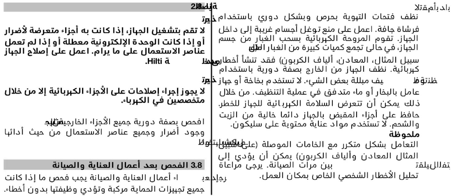
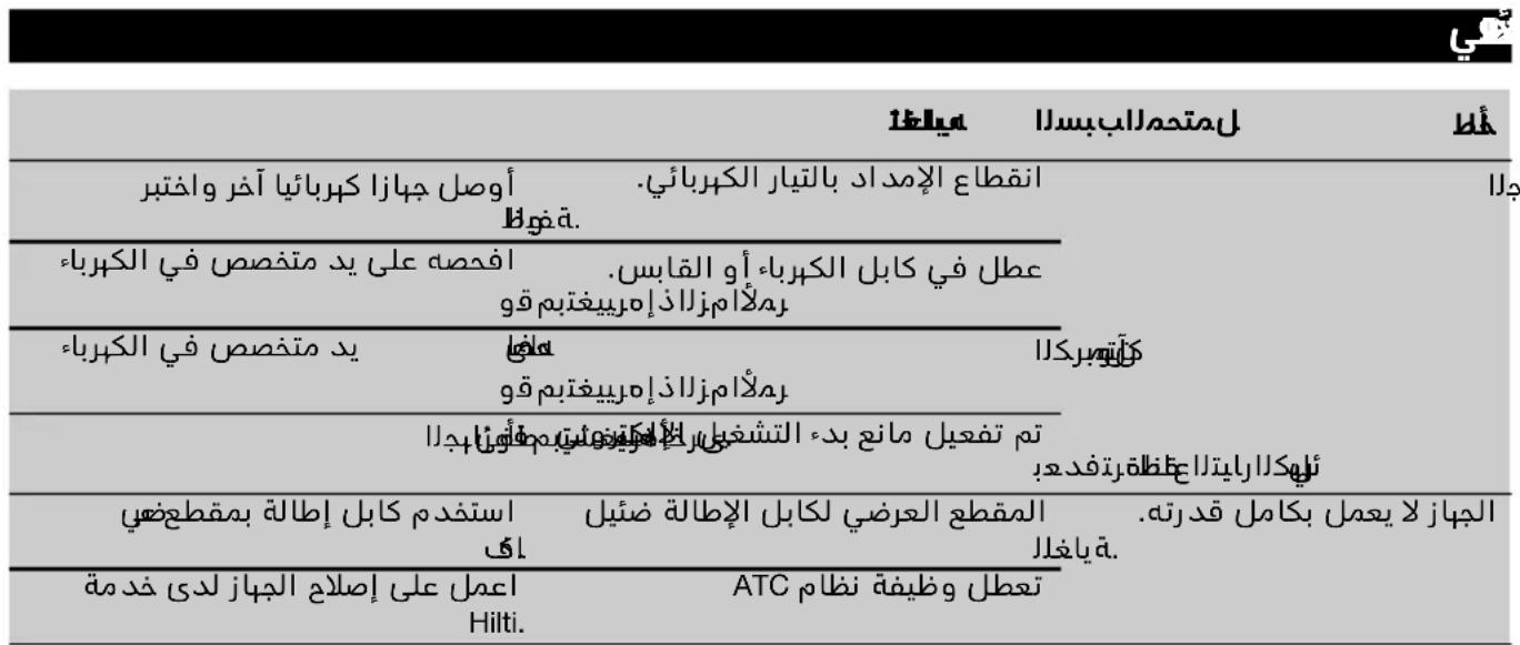
ar
1110

Jg.11 11 11 11 11 11 11 11 11 11 11 11 11 11 11 11 11 11 11 11 11 11 11 11 11 11 11 11 11 1
Jua.
!aJiaIlaIJIaJyIgSILg
g aol gall o 10 log aal al g u g jLg ayu ly kll o yog aay ggl aal gall lal
11
gI gI gI gI Hlti
aalll aalll gI gI gI gI gI gI gI gI gI gI gI gI gI gI gI gI gI gI gI gI gI gI gI gI gI gI gI gI gI gI gI gI gI gI gI gI gI gI gI gI gI gI gI gI gI gI gI gI gI gI gII. Jk
g jll lwwj ggl Ue y Bnll u 1 g 4uHilti gguj Jy qiaai I
JalsslloljllggeI Jlll Jaiu 100000000000000000000000000000000000000000000000000000000
Hilti jn Hii I g
IaH Jauuui 1J uuiuui uuiuui
Baiug tuiuuiuuiuuiuuiuuiuuiuuiuuiuuiuuiuuiuuiuuiuuiuuiuuiuuiuuiuuiuuiuuiuuiuuiuuiuuiuuiuuiuuiuuiuuiuuiuuiuuiuuiuuiuuiuuiuuiuuiuuiuuiuuiuuiuuiuuiuuiuuiuuiuuiuui uuuuuuuuuuuuuuuuuuuuuuuuuuuuuuuuuuuuuuuuuuuuuuuuuuuuuuuuuuuuuuuuuuuuuuuuuuuuuuuuuuuuuuuuuuuuuuuuuuuuuuuuuuuuuuuuuuuuuuuuuuuuuuuuuuuuuuuuuuuuuuuuuuuuuuuuuuuuuuuuuuuUUUUUUUUUUUUUUUUUUUUUUUUUUUUUUUUUUUUUUUUUUUUUUUUUUUUUUUUUUUUUUUUUUUUUUUUUUUUUUUUUUUUUUUUUUUUUUUUUUUUUUUUUUUUUUUUUUUUUUUUUUUUUUUUUUUUUUUUUUUUUUUUUUUUUUUUUUUUUUUUUUUUUUUUUUUUUUUUUUUUUUUUUUUUUUUUUUUUUUUU
Uulwgljlll 100000000000000000000000000000000000000000000
JU 1JU JU JU JU JU JU JU JU
g jg 8 lJb .suaa g a Jllb a J
Jaa 8 aala aagg. ggo oJoo JoJo
(du) 12
:JdaiJI dgaIbJI
Executive Vice President
Business Unit Power
Tools & Accessories
01/2012

Paolo Luccini
Head of BA Quality and Process
Management
Business Area Electric Tools &
Accessories
01/2012
Hilti Corporation
LI-9494 Schaan
Tel.: +423 /234 21 11
Fax:+423/2342965
www.hilti.com
1609 92A 0DW
Hilti = registered trademark of Hilti Corp., Schaan
W 3502 | 1013 | 00-Pos. 1 | 1
Printed in Germany © 2013
Right of technical and programme changes reserved S. E. & O.
71747 / A3

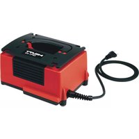


- ATC (Active Torque Control)
- Contents Page
- General information
- DANGER
- WARNING
- CAUTION
- NOTE
- Obligation signs
- Symbols
- Description
- Use of the product as directed
- Location of identification data on the power tool
- Type:
- en
- Grips
- Switches
- Items supplied as standard include:
- Starting current limitation
- Restart interlock
- Using extension cords
- Using extension cords outdoors
- Using a generator or transformer
- DC-EX 230/9" disc guard with guide carriage for cutting 2
- Guard with cover plate 3
- Consumables
- Technical data
- Safety instructions
- General Power Tool SafetyWarnings
- Workareasafety
- Electrical safety
- Personal safety
- Service
- Safety warnings for abrasive cutting-off operations
- Safety warnings specific for grinding and abrasive cutting-off operations
- Additional safety warnings specific for abrasive cutting-off operations
- through Additional safety instructions 5.6.1 Personal safety
- Power tool use and care
- Electrical safety
- Personal protective equipment
- Beforeuse
- Fitting the side handle
- Guard
- or res NOTE
- Adjusting the guard or guard with cover plate 5
- Fitting and removing the disc 67
- CAUPEN
- ing or
- eRNOTE
- 7Operation
- PROPFING
- tool (mu)
- Cutting
- ding tilt-
- Care and maintenance
- Care of the power tool
- 108.2beMaintenance
- Troubleshooting
- Disposal
- Manufacturer's warranty - tools
- EC declaration of conformity (original)
- Smerigliatrice angolare DCG 230-D / DAG 230-D
- Rengaring at maskinen
- FARE
- Kulmahiomakone DCG 230-D / DAG 230-D
- Characteristicas techniques
- Tpwixoc Tpoxoc DCG 230-D / DAG 230-D
- YINOAEIH
- a5.13Aopaaeia npoownov
- Xpron kai aVTiμεTOWIaŋ Tou nλEKTPiKoU εpyαλειou
- HAEKPTPIKn aopaaeio
- Vyn6.4 Xwpoc epyaiaic
- Anevepyonoinon
- ayn 7poyni eavekivnon
- YNOAEOH
- 8Φpovrida KαI Guvtnpnon
- PPOsOXH
- CHMBOJIbI
- PacnoJIOKeHne NdeHTnΦHKaUHOHHbIX DaHHbIX Ha HCTpyMeHTe
- 20nncahne
- NcnoIb3OBAHHe HHCTpyMeHTa no Ha3HaueHHIO
- PyKoRTHK
- NepeeknouaTeH/BBIKnouaTeH
- B cTaHApTHbI KOMnJIeKT NOCTaBKn BXOJrT:
- OrpaHnHTeIb nycKOBOrToKa
- AKTHBbI KOHTpOJI BpaaHooero MOMeHTa (ATC)
- YKA3AHHE
- BnoknapoT noBtphoro BkIIOueHn
- HcnoJb3OBAHHe ydInHHTeJIbHoro Ka6eIa
- 2.9ПримеениуднHTeIbHOro Ka6eB BHe NOMEeHH
- NcnoIb3ObaHne rehepaTopa nn TpaHcfoMaTopa
- 3aunTHbH KOxuy DC-EX 230/9" dIa OTpe3hIx pa6oT c HAnpaBnHOumm 2
- OCTOPOXHO
- YKA3AHNE
- 3aunTHbI KOHyxC HaKnaadKo
- Pacxohnbie MaTepeNaIbI
- 3JIeKtpnuecka 6e3onacHocTb
- Pa6oyee MecTo
- Hep56.5 CpeIcTba HnINBnDyalbHoN 3aunTbI
- NpOdrtoBka K pa6oTe
- ONACHO
- BHIMAHNE
- yctaHObKa 6OKOBOn pyKoRTKn
- 3aunTHbI KOxuyx
- YctaHOBka n CHTne 3aunTHoro KOxyxa/3aunTHoro KOxyxCnKa
- PerynnpOBka 3auHTHOKoJyxa/3aunTHoro KOJyxa C HAKnaIKOI 5
- YcTaHOBka H CHaTHe 3aUHTHOrO KOJyXa
- YORACHO
- Pa6oHn HnCtpymeHT c 6bICTpO3aXHMHOI raIKo Kwik-Lock
- YctaHOBka H CHrTHne pa6oery HnHCTpyMe 6bICTpo3aXHMHO raIKo Kwik-Lock 6
- 73Kcnpnyataaia
- BHHMAHNE
- 6BHIMMAHNE
- MOCTOPOXHO
- BAHMAHNE
- OCTOPOKHO
- Perylnpobka pykoTkn 8
- A6pa3nBHOe oTpe3aHne
- 06dnpouhoe uHΦoBaHne
- HAPKINB KIOUeHne/BBIKIOUeHne
- BkJIIOUeHHe
- nono 2.4 BbIKIOueHne
- BlnknpaTop noBtophoro BKIOUeHnA
- 39RA3AHNE
- yxoid n texHHueckoe 06cnyxHBaHne
- yxoid 3a HhctpyMeHToM
- POnck n yctpaHHeHne HEnCnpaBHOCTeN
- NORADIJUMS
- Atkartotas ieslegsanas noversana
- ALGUPÄRANE KASUTUSJUHEND
- Ketasloikur DCG 230-D / DAG 230-D
- 1julg jlaoswJolic jll Ugks
- aJJI aJg DC-EX 230/9" gabJI JauI pIaJI gbo 11.2
- wj
- aJgJ 12.2
- J 3
- aaiI aLgJI Uj5.6.5
- UgSg auiuJauIg 2.6.5 uuiu
- #
- aHnnpgbai Uglbwi pssuX
- (du) 12
- :JdaiJI dgaIbJI
Brand : HILTI
Model : DAG 230D
Category : Grinder