
WG118E - Grass trimmer WORX - Free user manual and instructions
Find the device manual for free WG118E WORX in PDF.
| Product type | Electric grass trimmer |
| Brand | Worx |
| Model | WG118E |
| Power supply | Corded (mains) |
| Rated voltage | 220-240 V ~ 50/60 Hz |
| Rated power | 550 W |
| No-load speed | 8900 min⁻¹ |
| Cutting diameter | 30 cm |
| Line diameter | 1.65 mm |
| Line length | 2 x 5 m |
| Weight | 2.8 kg |
| Sound pressure level | 85 dB(A) |
| Sound power level | 96 dB(A) |
| Hand-arm vibration | 5.7 m/s² (K=1.5 m/s²) |
| Protection | Protection class II (double insulation) |
| Functions | Grass trimming, brush cutting, edging |
| Included accessories | Protective guard, auxiliary handle, wheel kit, foldable stirrup |
| Adjustments | Telescopic shaft, adjustable auxiliary handle, adjustable cutting head |
| Line advancement system | Automatic and manual |
| Maintenance | Clean with dry cloth, store dry, no lubrication needed |
| Safety | Wear ear and eye protection, keep away from children, disconnect before maintenance |
| Spare parts | Use only genuine Worx parts |
Frequently Asked Questions - WG118E WORX
User questions about WG118E WORX
0 question about this device. Answer the ones you know or ask your own.
Ask a new question about this device
Download the instructions for your Grass trimmer in PDF format for free! Find your manual WG118E - WORX and take your electronic device back in hand. On this page are published all the documents necessary for the use of your device. WG118E by WORX.
USER MANUAL WG118E WORX
Not all the accessories illustrated or described are included in standard delivery.
TECHNICAL DATA
Type WG118E (1-designation of machinery, representative of Grass Trimmer)
| Rated Voltage 220-240V~50/60Hz |
| Power 550W |
| No Load Speed 8900/min |
| Cutting Diameter 30cm |
| Line Diameter 1.65mm |
| Line Length 2*5m |
| Machine Weight 2.8kg |
NOISE DATA
| A weighted sound pressure 85dB(A) | |
| KDA | 1.5dB(A) |
| A weighted sound power 96dB(A) | |
| Wear ear protection | |
VIBRATION INFORMATION
| Typical weighted vibration | 5.7m/s2, |
| Uncertainty K=1.5m/s2 |

WARNING: The vibration emission value during actual use of the power tool can differ
from the declared value depending on the ways in which the tool is used dependant on the
following examples and other variations on how the tool is used:
How the tool is used and the materials being cut or drilled.
The tool being in good condition and well maintained
Using the correct accessory for the tool and ensuring it is sharp and in good condition.
The tightness of the grip on the handles and if any anti vibration accessories are used.
And the tool is being used as intended by its design and these instructions.
This tool may cause hand-arm vibration syndrome if its use is not adequately managed

WARNING: To be accurate, an estimation of exposure level in the actual conditions of use
should also take account of all parts of the operating cycle such as the times when the tool
is switched off and when it is running idle but not actually doing the job. This may significantly reduce the exposure level over the total working period.
Helping to minimise your vibration exposure risk.
ALWAYS use sharp chisels, drills and blades
2-in-1 Grass Trimmer/Edger EN
Maintain this tool in accordance with these instructions and keep well lubricated (where appropriate)
If the tool is to be used regularly then invest in anti vibration accessories.
Avoid using tools in temperatures of 10^ or less
Plan your work schedule to spread any high vibration tool use across a NUMBER OF DAYS.
ACCESSIONS
Safety Guard 1
Auxiliary Handle 1
Edger Wheel 1
1
We recommend that you purchase your accessories from the same store that sold you the tool. Use good quality accessories marked with a well-known brand name. Choose the type according to the work you intend to undertake. Refer to the accessory packaging for further details. Store personnel can assist you and offer advice.
GENERAL POWER TOOL SAFETY WARNINGS

WARNING! When using the machine
the safety rules must be followed. For
your own safety and bystanders please read these instructions before operating the machine. Please keep the instructions safe for later use.
SAVE THESE INSTRUCTIONS
This appliance is not intended for use by persons (including children) with reduced physical, sensory or mental capabilities, or lack of experience and knowledge, unless they have been given supervision or instruction concerning use of the appliance by a person responsible for their safety.
Children should be supervised to ensure that they do not play with the appliance. If the supply cord is damaged, it must be replaced by the manufacturer, its service agent or similarly qualified persons in order to avoid a hazard.
SAFETY WARNINGS FOR LAWN TRIMMER
a) Wear protective glasses or goggles;
b) Never allow children or people unfamiliar with the instructions to use the machine;
c) Stop using the machine while people, especially children, or pets are nearby;
d) Only use the machine in daylight or good artificial light;
e) Before using the machine and after any impact, check for signs of wear or damage and repair as necessary;
f) Never operate the machine with damaged guards or without the guards in place;
g) Keep hands and feet away from the cutting means at all times and especially when switching on the motor;
h) Take care against injury from any device fitted for trimming the filament line length. After extending new cutter line always return the machine to its normal operating position before switching on;
i) Never fit metal cutting elements;
j) Never use replacement parts or accessories not provided or recommended by the manufacturer;
k) Disconnect the machine from the mains before checking, cleaning or working on the machine and when it is not in use;
I) Always ensure that ventilation openings are kept clear of debris;
MAINTENANCE
a) After use, disconnect the machine from the mains and check for damage;
b) When not in use store the machine out of the reach of children;
c) Mains powered trimmers should only be repaired by an authorised repairer;
d) Use only manufacturers recommended replacement parts and accessories.
- Read the instructions carefully,
- Be familiar with the controls and proper use of the equipment;
- Before use check the supply and extension cord for signs of damage or ageing,
- If the cord becomes damaged during use, disconnect the cord from the supply immediately. DO NOT TOUCH THE CORD BEFORE DISCONNECTING THE SUPPLY,
- Do not use the lawn trimmer (edge trimmer), if the cords are damaged or worn,

WARNING:
- Cutting elements continue to rotate after the motor is switched off,
- Keep extension cords away from cutting elements;
It is recommended that appliances should be supplied via a residual current device (RCD) with a tripping current of not more than 30mA .
SYMBOLS ASSEMBLY

Read operator's manual

Double insulation

Wear ear protection Wear eye protection
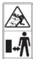
Keep bystanders away
Switch off! Remove plug from mains before adjusting, cleaning or if cable is entangled or damaged.

Do not expose to moisture.

This product has been marked with a symbol relating to removing electric and electronic waste. This means that this product shall not be discarded with household waste but that it shall be returned to a collection system which conforms to the European Directive 2002/96/CE. It will then be recycled or dismantled in order to reduce the impact on the environment. Electric and electronic equipment can be hazardous for the environment and for human health since they contain hazardous substances.

Edging

Trimming
1. ASSEMBLY OF THE SAFETY GUARD (See Fig. A)
Remove the screw from the Safety Guard (3) and fit the guard to the trimmer head; align the guard so it slides into the slots located on the trimmer head. Turn the tool over and secure the Safety Guard onto the trimmer head with the screw (a) provided.
2. ASSEMBLY OF THE EDGER WHEEL (See Fig. B)
With the tool right side up, slide the Edger Wheel (7) assembly onto the metal plate located on the side of the trimmer head. Make sure the grooves of the Edger Wheel assembly lock onto the metal plate; you will hear it click into place.
To remove the wheel assembly, press the release button (b) on the wheel and pull the wheel assembly upward.
OPERATING INSTRUCTIONS
INTENDED uSE
The machine is intended for the cutting of grass and weeds under bushes, as well as on slopes and edges that can not be reached with the lawn mower.

WARNING: THE CuTting HEAD CONTINUES TO ROTATE AFTER THE
TRIMMER HAS BEEN SWITCHED OFF. WAIT uTIL IT STOPS BEFORE LAYING THE TRIMMER DOWN.
Always wear eye protection. Never lean over the trimmer head. Rocks or debris can ricochet or be thrown into the eyes and face and cause blindness or other serious injury.
- Hold front handle with one hand and auxiliary handle with the other hand. Keep unit below waist level. Work only from your right to your left to ensure debris is thrown away from you. Without bending over, keep line near and parallel to the ground (perpendicular when edging) and not crowded into material being cut.
- Before operating, make sure both trimmer lines are extended. When trimming, make
2-in-1 Grass Trimmer/Edger EN
sure motor is running at full speed.
- Use only 1.65mm diameter cutting line. Other line sizes will not properly feed in the trimmer head and could cause serious injury. Never use other materials such as wires, string or rope, as this may break off during cutting and cause serious injury.
1. SPACER GuARD
Push the Flower Guard (4) in when edging and pull it out before trimming, as shown in Fig C. Before trimming or edging make sure the Flower Guard is locked firmly in position.
2. ADJUSTMENT OF THE TELESCOPIC SHAFT (See Fig. D)
Unscrew the Locking Collar (2) clockwise to unlock, as indicated. Adjust the length of the Telescopic Shaft (5)to the most comfortable length. Tighten the Locking Collar counterclockwise to lock, as indicated.
3. MAIN HANDLE ROTATION
First, hold down the lower housing with your foot and pull upward on the Telescopic Shaft (5). Then rotate the Telescopic Shaft clockwise 90 degrees (See Fig.E1) and release; the Shaft will be locked in position automatically (See Fig. E2).
4. ADJuSTING THE AuxILIARY HANDLE (See Fig. F)
Pull up the Auxiliary Handle Locking Lever (9). Hold the lever and rotate the Auxiliary Handle (6) to the most comfortable and balanced position (See Fig F).
Release the lever, your Auxiliary Handle has been locked.
5. ELECTRICAL SuPLY CABLE STRAIN RELIEF (See Fig. G)
For strain relief of the cable, form a loop at the end of the extension cable. Locate the cable through the handle and secure by placing the loop over the Cable Hook and pull the cable back.
6. ADJUSTMENT OF TRIMMER HEAD ANGLE
To adjust the trimmer head angle downwards, put one foot on the motor housing, then grip the Rear and Auxiliary
handles, and apply adequate force to adjust, as shown in Fig. H1.
To adjust the trimmer head angle upwards, put one foot on the Safety Guard (3), then grip the Rear and Auxiliary handles and apply adequate force to adjust, as shown in Fig. H2.
7. uSING THE ON/OFF TRIGGER
Press and hold the on/off trigger to start the trimmer. Release to stop
8. TRIMMING
Hold the bottom of the trimmer head just above the ground and at a slight angle. Allow only the tip of line to make contact with the grass. Let the trimmer line work at its own pace; do not force the trimmer line into the work area.
9. EDGING (See Fig. I)
First, rotate the Rear Handle (1) 90 degree clockwise (See "Main Handle Rotation", Fig. E1&E2).
Adjust the trimmer head angle to be the lowest horizontal setting (See "Adjustment of the Trimmer Head Angle", Fig H1). Then position the Edger Wheel (7) on the ground for edge mode (See Fig. 1). There are two white lines, located on each end of the Safety Guard (3), that show the cutting plane of the trimmer line. Align these marks with the edge of your lawn.
While edging, allow the tip of the line to make contact. Do not force the line. The wheel helps to prevent the unit from touching the ground. Take extra caution while edging as objects can be thrown from the trimmer line.
10. AUROMATIC LINE FEED SYSTEM
When initially switching on the trimmer, a small length of line is fed out.
A 'clattering' noise will be heard for a short time. This is normal and is caused by the line being cut by the line cutter. Once the line is cut to the correct length, the 'clattering' noise will stop and the trimmer motor will run at full speed.
To feed more line, stop the trimmer completely, then restart, allowing the motor to reach full speed. Repeat this until you hear the 'clattering' noise of the line cutting. (Do not repeat this procedure more than 6 times)
11. MANuALLY FEEDING THE LINE (See Fig. J)
Press and release the Line Feed Button (15) (See Fig. J) whilst gently pulling out on one of the lines until it has reached the line cutter. When the required amount of line is fed out, gently pull on the second line (there is no need to press the Line Feed Button again). If the line extends past the line cutter, too much line has been fed out.
If too much line is fed out, remove the spool cap and click the spool counter-clockwise until the line is at the desired length.
12. REMOVING THE CAP
Press and hold in the two Cap Release Latches (11) (See Fig K).
Pull the Cutting Head Cover (10) away from the Cutting Head (13). Keep the Cutting Head Cover and the inside of the Cutting Head clean from debris. To replace the Cutting Head Cover, press it firmly onto the spool holder. Ensure that it is correctly connected by trying to remove it without depressing the two Cap Release Latches.
13. CHANGING THE LINE SPOOL
First take off the Cutting Head Cover (10) and remove the old Spool (12). Place the new Spool onto the Cutting Head (13). Feed one line through the Eyelet (14), and then repeat for the second line. Reattach the Cutting Head Cover.
WARNING! Your Trimmer is designed to only use line with a maximum diameter of 0.065 (1.65mm". Only use nylon line.
IMPORTANT - Always wind the line onto the upper section of the spool first.
14. TO MANuALLy WIND LINE
Take approximately 5m of line and insert 15mm of line into one of the holes in the upper section of the Spool (12) (See Fig L1)
Wind the line in the direction of the arrows on the top of the Spool. Repeat process with separate piece of line on lower section of Spool (See Fig. L2 & L3).
Leave approximately 100mm of line unwound and place it into the cleat. Repeat on the lower section of the Spool.
Care should be taken to ensure that the line is neatly coiled on the Spool (See Fig L4).
Failure to do so will impair the efficiency of the automatic line feed.
Then fit the Spool as described above in "Changing the Line Spool".
MAINTENANCE
After use, disconnect the machine from the electrical outlet and check for damage. Your trimmer requires no additional lubrication or maintenance. There are no user serviceable parts in your trimmer. Electric powered trimmers should only be repaired by an authorized repairer. Use only manufacturers recommended replacement parts and accessories.
Never use water or chemical cleaners to clean your trimmer. Wipe clean with a dry cloth. Always store your trimmer in a dry place out of the reach of children. Keep the motor ventilation slots clean. If you see some sparks flashing in the ventilation slots, this is normal and will not damage your trimmer.
ENVIRONMENTAL PROTECTION
This product has been marked with a symbol relating to removing electric and electronic waste. This means that this product shall not be discarded
with household waste but that it shall be returned to a collection system which conforms to the European Directive 2002/96/ CE. It will then be recycled or dismantled in order to reduce the impact on the environment. Electric and electronic equipment can be hazardous for the environment and for human health since they contain hazardous substances.
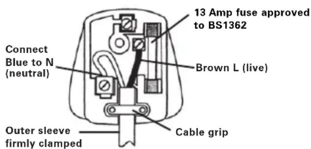
PLUG REPLACEMENT (ONLY FOR REWIRABLE PLUG OF UK & IRELAND)
If you need to replace the fitted plug then follow the instructions below.
IMPORTANT
The wires in the mains lead are colored in accordance with the following code:
BLUE =NEUTRAL
Brown = Live
As the colors of the wires in the mains lead of this appliance may not correspond with the colored markings identifying the terminals in your plug, proceed as follows. The wire which is colored blue must be connected to the terminal which is marked with N. The wire which is colored brown must be connected to the terminal which is marked with L.
WARNING! Never connect live or neutral wires to the earth terminal of the plug. Only fit an approved 13ABS1363/A plug and the correct rated fuse.
NOTE: If a moulded plug is fitted and has to be removed take great care in disposing of the plug and severed cable, it must be destroyed to prevent engaging into a socket.
DECLARATION OF CONFORMITY
Declare that the product, Description 2-in-1 Grass Trimmer/Edger Type WG118E (1-designation of machinery, representative of Grass Trimmer)
Function Cutting grass and weeds
Complies with the following Directives, Machinery Directive 2006/42/EC
Electromagnetic Compatibility Directive 2004/108/EC
RoHS Directive 2011/65/EU
Noise Emission in the Environment by Equipment for Use Outdoors Directive 2000/14/EC amended by 2005/88/EC
-
Conformity Assessment Procedure as per Annex VI
-
Measured Sound Power Level 95.5dB(A)
- Declared Guaranteed Sound Power Level 96dB(A)
The notified body involved
Name: Intertek Testing & Certification Ltd
Address: Davy Avenue, Knowlhill, Milton Keynes, MK5 8NL
Standards conform to, EN 60335-1 EN 60335-2-91 EN 62233 EN ISO 3744 EN 55014-1 EN 55014-2 EN 61000-3-2 EN 61000-3-3
The person authorized to compile the technical file,
Name Russell Nicholson
Address Positec Power Tools (Europe)
Ltd, PO Box 152, Leeds, LS10 9DS, UK

Name: Intertek Testing & Certification Ltd
Anschrift: Davy Avenue, Knowlhill, Milton
Keynes, MK5 8NL
Werte nach
EN 60335-1 EN 60335-2-91
EN 62233 EN ISO 3744
EN 55014-1 EN 55014-2
EN 61000-3-2 EN 61000-3-3
Ltd, PO Box 152, Leeds, LS10 9DS, UK
2013/02/20
Leo Yue
INFORMATIONS RELATIVES AU BRUIT
INFORMATIONS RELATIVES AUX VIBRATIONS
Nome Intertek Testing & Certification Ltd Indirizzo:Davy Avenue, Knowlhill,Milton Keynes, MK5 8NL
Conformera,
EN 60335-1 EN 60335-2-91
EN 62233 EN ISO 3744
EN 55014-1 EN 55014-2
EN 61000-3-2 EN 61000-3-3
Ltd, PO Box 152, Leeds, LS10 9DS, UK


2013/02/20
Leo Yue
Ltd, PO Box 152, Leeds, LS10 9DS, UK


2013/02/20
Leo Yue
3. ROTACAO DO MANiPuLO PRINCIPAL
Segurando a parte inferior puxe a haste para cima,进驻 rode 90 graus no sentido dos ponteiros do relógio (ver Fig E1),进驻 liberta-a, a haste irá bloquear automaticamente na posicao. (Ver Fig. E2)
4. AJuSTAMENTO DO MANiPuLO AuxILIAR (Ver Fig. F)
Cumpre as següntes Directivas:
Directiva respeita a Maquinas 2006/42/EC
Nome: Intertek Testing & Certification Ltd
Morada: Davy Avenue, Knowlhill, Milton Keynes, MK5 8NL
Ltd, PO Box 152, Leeds, LS10 9DS, UK

2013/02/20
Leo Yue
Gestor de Qualidade POSITEC
| 1. HANDVAT ACHTER |
| 2. VERGRENDELKRAAG |
| 3. BESCHERMKAP |
| 4. AFSTANDBESCHERMER |
| 5. TELESCOOPSTEEL |
| 6. ExTRA HANDVAT |
| 7. WIEL VOOR KANTEN SNIJDEN |
| 8. DRAADSNIJDER |
| 9. VERGRENDELKNOP ExTRA HANDGREEP |
| 10. AFDEKKAP SNIJGEDEELTE (zIE SEE FIG K ) |
| 11. PAL VOOR LOSMAKEN AFDEKKAP (zIE SEE FIG K) |
| 12. SPOEL (zIE FIG K) |
| 13. SNIJGEDEELTE (zIE FIG K) |
| 14. OOGJE (zIE FIG K) |
| 15. KNOP VOOR DRAADTOEVOER (zIE FIG J) |
2000/14/EC amended by 2005/88/EC
-
Konformitetstestprocedure Annex VI
-
Målt niveau for lydeffekt 95.5dB(A)
-
Deklareret garanteret niveau for lydeffekt
96dB(A)
Afprvningsorgan involveret
Navn: Intertek Testing & Certification Ltd
Adresse: Davy Avenue, Knowlhill, Milton
Keynes, MK5 8NL
Standarder i overensstemmelse med,
EN 60335-1 EN 60335-2-91
EN 50366 EN 62233
EN ISO 3744 EN 55014-1
EN 55014-2 EN 61000-3-2
EN 61000-3-3
Ltd, PO Box 152, Leeds, LS10 9DS, UK


2013/02/20
Leo Yue
2000/14/EC amended by 2005/88/EC
Nimi: Intertek Testing & Certification Ltd
Osoite: Davy Avenue, Knowlhill, Milton
Keynes, MK5 8NL
Ltd, PO Box 152, Leeds, LS10 9DS, UK


2013/02/20
LeoYue
BEHOLD DISSE INSTRuKSENE
2000/14/EC amended by 2005/88/EC
Adi: Intertek Testing & Certification Ltd
Adres: Davy Avenue, Knowlhill, Milton Keynes, MK5 8NL
Uyduugu standartlar
EN 60335-1 EN 60335-2-91
EN 62233 EN ISO 3744
EN 55014-1 EN 55014-2
EN 61000-3-2 EN 61000-3-3
PO Box 152, Leeds, LS10 9DS, UK


2013/02/20
Leo Yue
POSITEC Kalite Mūdurū
H xpnon tou owootou TnapeAkoevou yia to epyaaleio kai n diaoqalion otI KoBc KaKa Bpiketai Oe KaN kaTaoTaon.
To k Tou Tpooepouv oi lae c kal to av xpnoiotiouovtai avtikpaadogikakapελκόμεva.
Kai av to epyaaleio xpnoioutoieitai Tov tpoTTOU TPOBtETaI aTIO n OxEiaon Tou KAI TIG TAPouoe oDnyieC.
To ouykekiévo εpyaεio μnopei va πpokαεσει σύνδρopo tpéμoulou στα xερia kai touc βpaxioves σε πepiTTwON avεξελεyKTns xphons tou.

IPOEIOHOH: Ia va eiaote akeic, kata nTv ekTImn Tns otAouc EKTeoC otis TTpaayatike c ouvthekc xphonc thpETe iTioan v lauabavoume utoyn ola ta epn tou kukau
2-σε-1 XλookoTTIKó/θαμvokoTTIKó GR
Ovoua: Intertek Testing & Certification Ltd
u Davy Avenue, Knowlhill, Milton
Keynes, MK5 8NL
Ovoua Russell Nicholson
Ltd, PO Box 152, Leeds, LS10 9DS, UK


2013/02/20
Leo Yue
Ytueuovoc ts POSITE yia tioTnac
| 1. 3AADЯ РУКОТKA |
| 2. 3AJКIMнЯ MYФТА |
| 3. 3AùNTHOE OGRAPKДЕНЕ |
| 4. 3AùNTHbI ΜΙΝΤΟΚ |
| 5. TELECKОПИССКА ΜΙΤΑΝΑ |
| 6. ДОПОЛНTEЛьнÀРУКОТKA |
| 7. KPOMOчhoe KОЛECO |
| 8. PE3AK ЛECHК |
| 9. 3AJКIMнь ПычAxKOK BCПOMORATEЛьнOH руЧК |
| 10. KOЛПАК PEXKUŞÉN TOLOBК (См. Рс. К) |
| 11. 3AùSEЛKA KPEПLEHЯ KOLПАKA (См. Рс. K) |
| 12. БОБИHA (См. Рс. K) |
| 13. PEXKUŞÄR TOLOBKA (См. Рс. K) |
| 14. OTBEPCTNE (См. Рс. K) |
| 15. KHOПКА ПОДАЧ NELCKN (См. Рс. L) |
He BCE npHnHaIeXHoCTN, ONncAHhbI B pyKOBoDCTBe nJI IN ppeCTaBJIeHHbIe Ha pncyHKe, BKJIoueHbI B CTaNdApTHyIO NOcTabKy.
TEXHNUECKNE XAPAKTEPNUCTUKN
MoJeNei WG118E (1-06o3NaueHne HnCtpymeHa, Tpmmep)
Tenez you a bonn distance.
OTKJIIOUHTb!OTcoeINHInTe pa3beM NITaHnO T cETn npeD HAcTPOIKoN, UcIcTKoB, B Clyuayx 3aNyTbIBAHn INI NOBpeXdEHn Ka6eJ.

NCKHOUHTeJIbHO CJeCKO,MAKcIMaJIbHbI INaMeTp KOTOpO CoCTaBnIeT 1,65MM.
IcnoJb3yTe TOJIbKO HeHNOHOByO JeCKy.
BHIMAHNE-Chaayana Bcerda HamaTbIbaTe Jecky Ha BepxHIO Yo Actb KaTyuKn.
14. KAK CMOTATb JIECKY BPUHyIO
Bo3bMnTe npi6n3nteIbHO 5 MeTPOB neCKN. BCTaBte 15 MM neCKN B OJHO n3 OTBepCTnB BepxHeY aactn 6o6uHbI n HAMOTaHTe JecKy B HanpaBHeHH, 6o3HaueHHom CTpeJIkAmn CBepxv 6o6uHbI.
IOBTOPnTe OnpaCIO CpyrIM KycKOM NcKN Ha HxHne YactN KaTyuKn (CM.Pnc.L2&L3). Bcerda HamaTbBaIte Jecky ChaHa Ha BepXHIOU YaCTb 606nHbl.
OCTaBtpe npu6n3nteJbHo 100MM JneKn He HAMOTAHHO IN NOMeCTHTe B 3axKm. NOBTOPTe 3TN DeIcTBnI DnHnxHe YacTn 6o6nHbl.
Y6eIntecb, yTO Jncka aKKypaTHo HAMOTHa Ha 6o6nHy. HeBbINONHeHne 3TOrO Tpe6OBaHn CHN3NT 3ΦΦeKTHBHOCTb ABTomATnueCKo NODaHn Jnckn.
Iocne 3TOrO yCTaHOBnTe 6o6nHy, KaK OINcaHo B pa3dene "BbInonHnTe cJeDyouune DeiCTBnA, YTO6bl yCTaHOBnTB 6o6nHy neckn".
TEXHNUECKOE OBCJNYXINBAHNE
Nocne nCnoJb3ObaHn OTKIouHTe ra3OHOKoNkY
OT NCTOCHNA NITaHnI INPOBepbTe ee Ha NOBpeXeHnI.B INHcTpymHe TOTcyTCTBYOT DeTaII, NOJIeXaUne O6CnyKINBAHIO IONb3OBaTeIeM. 3JIeKTPnueCKNe rA3OHOKOcnIKn IODJIeXaT peMOHTy TOIbKO ABTOPN3OBAHbIM peMOHTbIM cEHrOM. IVcNoJIb3yIne ToIbKO 3aNaChbIe qACTn I nPncnOCo6JIeHnRA WORX. HNKOrDa He NCNoJIb3yIne BODy IIIN XIMNUeCKNe YnCTaUe CpeDCTBa DJIa YnCTKn 3JIeKTPoINHcTpymEHa. IpOTnpaIne erO cyXoJ TKaHbI. Bcerda xpaHIne 3JIeKTPoINHcTpymEHT B cyXOM MeCe. CoedePxIne B YnCTOTE BEHTNJLAAUHHbIe OTBepCTnI DVBraTeJIa. OOnuaiTe OT PbIIN BCE pa6Ovne opraHbI ynpabLeHnI.
3AUNTA OKYKAIOUEN CPEbl

Данhoeиздении Имeel МаркИровky, OTHOCЯуюс K yTuIN3aцIN 3JIeKTPuYeCKnX IJIeKTPoHHbIX OTxOIOB.
3TO O3Haayet, YTO daHHoe 13JeJIne
HeIb3yUTIN3HPOBaT BMeCTe C 6bITOBIMN OTXoAMn, erO cJeDyET BO3BpaAaTb B NYHKtbl IpnEma, KOToPbIE COOTBeTCTByOT EbponeckOJ DInpeKTIbe 2002/96/CE. BnocJIeDCTBmN OHO 6yTe IOBeprHyTo nepepa60Te nII pa3o6paHO B CEJAX CHIXKeHnB BpeHOrO BO3DeIcTBnRA Ha OKpykaIOUyIO cpey. 3NeKtpueeckoe n 3NeKTPoHHoe o6OpUdoBaHne MoKeT IpeDCTaBnTb ONaCHOCTb dIg OkpykaHOSeI CpeDbI IN 3dOpOBbY qeIOBeka, NOCKoJIbKy OHO CODepxNT BpeDhble BeuceCTBa.
ДЕКЛAPALA COOTBETCTBЯ
KoMaHn, POSITEC Germany GmbH Konrad-Adenauer-Ufer 37 50668Kln
3aBjaT, yTo n3deJIne
OncaHnE 2 B 1 ra3oHokocnIka/
KpOMKoo6pe3aTeIb
MoJeN WG118E (1-06o3NaueHne
HHCTpyMeHTa, TpMMep)
Ha3NaueHne Pe3Kn TpaBbl N copHraKN
COOTBETCTBYET NOLOXKeHnM DInpeKTHB,
DInpeKTHBa O MaUHHax N MExaHn3Max 2006/42/EC
DInpeKTHBa NO 3JIeKTPOMarHnTHoN
COBMecTmOCTn 2004/108/EC
DInpeKTHBa NO ORpaHnueHnIO nCNoJb3OBaHnRA
BpeNbIx BeIeCTB 2011/65/EU
YPOBHeH Wyma COOTBeTCTByeT HOpMaTHBAM IO
O6OpyIOBaHNIO IJRA HApUxHOro NcNoJIb3OBAHn
2000/14/EC amended by 2005/88/EC
-IPoueDpya OueHKN COBMeCTUMOCTN COJIaCHO
Annex VI

- TECHNICAL DATA
- NOISE DATA
- VIBRATION INFORMATION
- This tool may cause hand-arm vibration syndrome if its use is not adequately managed
- ACCESSIONS
- GENERAL POWER TOOL SAFETY WARNINGS
- SAVE THESE INSTRUCTIONS
- SAFETY WARNINGS FOR LAWN TRIMMER
- MAINTENANCE
- WARNING:
- SYMBOLS ASSEMBLY
- ASSEMBLY OF THE SAFETY GUARD (See Fig. A)
- ASSEMBLY OF THE EDGER WHEEL (See Fig. B)
- OPERATING INSTRUCTIONS
- INTENDED uSE
- WARNING: THE CuTting HEAD CONTINUES TO ROTATE AFTER THE
- TRIMMER HAS BEEN SWITCHED OFF. WAIT uTIL IT STOPS BEFORE LAYING THE TRIMMER DOWN.
- 2-in-1 Grass Trimmer/Edger EN
- SPACER GuARD
- ADJUSTMENT OF THE TELESCOPIC SHAFT (See Fig. D)
- MAIN HANDLE ROTATION
- ADJuSTING THE AuxILIARY HANDLE (See Fig. F)
- ELECTRICAL SuPLY CABLE STRAIN RELIEF (See Fig. G)
- ADJUSTMENT OF TRIMMER HEAD ANGLE
- uSING THE ON/OFF TRIGGER
- TRIMMING
- EDGING (See Fig. I)
- AUROMATIC LINE FEED SYSTEM
- MANuALLY FEEDING THE LINE (See Fig. J)
- REMOVING THE CAP
- CHANGING THE LINE SPOOL
- TO MANuALLy WIND LINE
- ENVIRONMENTAL PROTECTION
- PLUG REPLACEMENT (ONLY FOR REWIRABLE PLUG OF UK & IRELAND)
- IMPORTANT
- BLUE =NEUTRAL
- Brown = Live
- DECLARATION OF CONFORMITY
- INFORMATIONS RELATIVES AU BRUIT
- INFORMATIONS RELATIVES AUX VIBRATIONS
- ROTACAO DO MANiPuLO PRINCIPAL
- AJuSTAMENTO DO MANiPuLO AuxILIAR (Ver Fig. F)
- BEHOLD DISSE INSTRuKSENE
- TEXHNUECKNE XAPAKTEPNUCTUKN
- KAK CMOTATb JIECKY BPUHyIO
- TEXHNUECKOE OBCJNYXINBAHNE
- 3AUNTA OKYKAIOUEN CPEbl
- ДЕКЛAPALA COOTBETCTBЯ
Brand : WORX
Model : WG118E
Category : Grass trimmer