
WG155E - String Trimmer WORX - Free user manual and instructions
Find the device manual for free WG155E WORX in PDF.


| Product Type | Cordless String Trimmer |
| Brand | Worx |
| Model | WG155E |
| Battery Voltage | 20 V |
| Battery Type | Lithium-ion (compatible with Worx Power Share) |
| Included Battery Capacity | 2.0 Ah |
| Typical Runtime | 20-30 minutes |
| Cutting Width | 30 cm |
| Cutting Line Diameter | 1.6 mm |
| Rotation Speed | 8,000 rpm |
| Swivel Head | Yes (90° tilt) for edging |
| Adjustable Handle | Yes, tool-free |
| Weight (with battery) | 2.8 kg |
| Weight (without battery) | 2.3 kg |
| Sound Level | 85 dB(A) |
| Main Functions | Trimming, edging, light cutting |
| Maintenance | Clean after each use, replace worn line |
| Safety | Double insulation, overload protection, automatic shut-off in case of blockage |
| Available Spare Parts | Cutting lines, cutting head, battery, charger |
| Repairability | Easy line and battery replacement; sealed motor |
Frequently Asked Questions - WG155E WORX
User questions about WG155E WORX
0 question about this device. Answer the ones you know or ask your own.
Ask a new question about this device
Download the instructions for your String Trimmer in PDF format for free! Find your manual WG155E - WORX and take your electronic device back in hand. On this page are published all the documents necessary for the use of your device. WG155E by WORX.
USER MANUAL WG155E WORX
natural_image
Line drawing of a mechanical device with articulated arms and a handle, labeled '20V' (no text or symbols on the diagram itself)20VMAX ^* LITHIUM
| Cordless Lawn Trimmer/Lawn Edge Trimmer | EN | P06 |
| Schnurloser Rasentrimmer/Rasenkantentrimmer | D | P16 |
| Taille-bordures sans fil/taille-haies | F | P28 |
| Tagliaerba a batteria/taglia siepi | I | P40 |
| Cortasetos/bordeadora sin cables | ES | P52 |
| Aparador de relva sem fio/corte de rebordos de relvado | PT | P64 |
| Snoerloze grastrimmer/graskanttrimmer | NL | P76 |
| Akku-græstrimmer/græskanttrimmer | DK | P88 |
| Johdoton ruohotrimmeri/ruohon reunatrimmeri | FIN | P99 |
| Trådløs gressklipper/kantklipper | NOR | P110 |
| Sladdlös gräsmattetrimmer/kanttrimmer gräsmatta | SV | P121 |
| Kablosuz çim biçme makinesi/kablosuz çim kenar düzeltme makinesi | TR | P131 |
| Ασύρματη μηχανή κουρέματος/ψαλιδίσματος γκαζόν | GR | P143 |
| Ακκυμуляторный триммер газонов/триммер для краев газонов | RU | P155 |
| Original instructions EN |
| Originalbetriebsanleitung D |
| Notice originale F |
| Istruzioni originali I |
| Manual original ES |
| Manual original PT |
| Oorspronkelijke gebruiksaanwijzing NL |
| Original brugsanvisning DK |
| Alkuperäiset ohjeet FIN |
| Original driftsinstruks NOR |
| Bruksanvisning i original SV |
| Orijinal işletme talimatı TR |
| Прштотипо обнүйшв хрήσης GR |
| Оригинальное руководств-во по эксплуатации RU |


natural_image
Technical diagram of a mechanical assembly with labeled component 'a' (no text or symbols beyond label)A1A2B1
natural_image
Technical line drawing of a mechanical assembly with labeled component 'a' (no readable text or symbols)
natural_image
Mechanical tool diagram showing a lever and handle assembly with an arrow indicating motion (no text or symbols)
natural_image
Mechanical robotic arm diagram showing a joint with a labeled component 'b' and an arrow indicating motion (no text or symbols beyond label)
B2CD

natural_image
Mechanical component diagram showing a shaft with a central bracket and two mounting holes, with an upward arrow indicating motion direction (no text or symbols)EF1F2

natural_image
Mechanical assembly diagram showing a lever mechanism with a handle and lever, no text or symbols present
natural_image
Mechanical assembly diagram showing a lever mechanism with a handle and lever, no text or symbols present
natural_image
Mechanical assembly diagram showing a shaft and connecting rod with a mechanical component, no text or symbols present
natural_image
Mechanical assembly diagram showing a shaft and connecting rod with a mechanical component, no text or symbols present
natural_image
Diagram of a manual tool with a curved arrow indicating rotation (no text or symbols present)GH1H2

natural_image
Silhouette of a person using a handheld device with a curved arrow indicating motion (no text or symbols)
natural_image
Silhouette of a person using a handheld device with a curved arrow indicating motion (no text or symbols)
natural_image
Silhouette of a person using a vacuum cleaner (no text or symbols visible)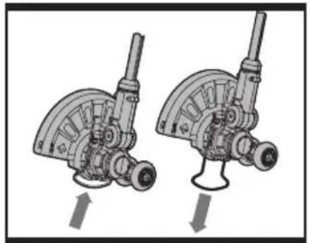
natural_image
Mechanical assembly diagram showing two views of a mechanical device with no visible text or symbols
natural_image
Silhouette of a person using a manual power tool on grass (no text or symbols visible)
natural_image
Technical diagram of a mechanical component with labeled part 16 (no text or symbols beyond label)IJK1

K2
- REAR HANDLE
- AUXILIARY HANDLE
- TELESCOPIC SHAFT
- LOCKING KNOB
- AUXILIARY HANDLE LOCKING LEVER
- SAFETY GUARD
- SPACER GUARD
- EDGER WHEEL
- LINE CUTTER
- BATTERY PACK
- CUTTING HEAD COVER (See Fig. K2)
- CAP RELEASE LATCH (See Fig. K2)
- SPOOL (See Fig. K2)
- CUTTING HEAD (See Fig. K2)
- EYELET (See Fig. K2)
- LINE FEED BUTTON (See Fig. K1)
Not all the accessories illustrated or described are included in standard delivery.
TECHNICAL DATA
Type WG155E (130-169-designation of machinery, representative of Cordless Grass Trimmer)
| Voltage 20V Max* Lithium | |
| No load speed 8500/min | |
| Cutting diameter 25cm | |
| Line diameter 1.65mm | |
| Charging time 3hr | |
| Machine weight | 2.4kg |
*Voltage measured without workload. Initial battery voltage reaches Maximum of 20 volts. Nominal voltage is 18 volts.
NOISE INFORMATION
A weighted sound pressure 77dB(A)
A weighted sound power 94dB(A)
K_pA & K_wA 3.0dB(A)
Wear ear protection when sound pressure is over 80dB(A)

Typical weighted vibration a_h=4.5m/s^2
Uncertainty K 1.5m/s ^4

WARNING! The vibration emission value during actual use of the power tool can differ from the declared value depending on the ways in which the tool is used dependant on the following examples and other variations on how the tool is used:
How the tool is used and the materials being cut or drilled.
The tool being in good condition and well maintained.
The use the correct accessory for the tool and ensuring it is sharp and in good condition.
The tightness of the grip on the handles and if any anti vibration accessories are used.
And the tool is being used as intended by its design and these instructions.
This tool may cause hand-arm vibration syndrome if its use is not adequately managed.

WARNING! To be accurate, an estimation of exposure level in the actual conditions of use should also take account of all parts of the operating cycle such as the times when the tool is switched off and when it is running idle but not actually doing the job. This may significantly reduce the exposure level over the total working period.
Helping to minimize your vibration exposure risk.
ALWAYS use sharp chisels, drills and blades.
Maintain this tool in accordance with these instructions and keep well lubricated (where appropriate).
If the tool is to be used regularly then invest in anti vibration accessories.
Avoid using tools in temperatures of 10^ C or less.
Plan your work schedule to spread any high vibration tool use across a number of days.
ACCESSORIES
Safety guard 1
Charger (WA3739) 1
Battery pack (WA3520) 1
Auxiliary handle 1
Edger wheel 1
We recommend that you purchase your accessories from the same store that sold you the tool. Use good quality accessories marked with a well-known brand name. Choose the type according to the work you intend to undertake. Refer to the accessory packaging for further details. Store personnel can assist you and offer advice.
GENERAL POWER TOOL SAFETY WARNINGS

WARNING: Read all safety warnings and all instructions. Failure to follow
the warnings and instructions may result in electric shock, fire and/or serious injury.
Save all warnings and instructions for future reference.
The term “power tool” in the warnings refers to your mains-operated (corded) power tool or battery-operated (cordless) power tool.
1) WORK AREA SAFETY
a) Keep work area clean and well lit.
Cluttered or dark areas invite accidents.
b) Do not operate power tools in explosive atmospheres, such as in the presence of flammable liquids, gases or dust. Power tools create sparks which may ignite the dust or fumes.
c) Keep children and bystanders away while operating a power tool. Distractions can cause you to lose control.
2) ELECTRICAL SAFETY
a) Power tool plugs must match the outlet. Never modify the plug in any way. Do not use any adapter plugs with earthed (grounded) power tools. Unmodified plugs and matching outlets will reduce risk of electric shock.
b) Avoid body contact with earthed or grounded surfaces, such as pipes, radiators, ranges and refrigerators. There is an increased risk of electric shock if your body is earthed or grounded.
c) Do not expose power tools to rain or wet conditions. Water entering a power tool will increase the risk of electric shock.
d) Do not abuse the cord. Never use the cord for carrying, pulling or unplugging the power tool. Keep cord away from heat, oil, sharp edges or moving parts. Damaged or entangled cords increase the risk of electric shock.
e) When operating a power tool outdoors, use an extension cord suitable for outdoor use. Use of a cord suitable for outdoor use reduces the risk of electric shock.
f) If operating a power tool in a damp location is unavoidable, use a residual
current device (RCD) protected supply. Use of an RCD reduces the risk of electric shock.
3) PERSONAL SAFETY
a) Stay alert, watch what you are doing and use common sense when operating a power tool. Do not use a power tool while you are tired or under the influence of drugs, alcohol or medication. A moment of inattention while operating power tools may result in serious personal injury.
b) Use personal protective equipment. Always wear eye protection. Protective equipment such as dust mask, non-skid safety shoes, hard hat, or hearing protection used for appropriate conditions will reduce personal injuries.
c) Prevent unintentional starting. Ensure the switch is in the off-position before connecting to power source and/or battery pack, picking up or carrying the tool. Carrying power tools with your finger on the switch or energising power tools that have the switch on invites accidents.
d) Remove any adjusting key or wrench before turning the power tool on. A wrench or a key left attached to a rotating part of the power tool may result in personal injury.
e) Do not overreach. Keep proper footing and balance at all times. This enables better control of the power tool in unexpected situations.
f) Dress properly. Do not wear loose clothing or jewellery. Keep your hair, clothing and gloves away from moving parts. Loose clothes, jewellery or long hair can be caught in moving parts.
g) If devices are provided for the connection of dust extraction and collection facilities, ensure these are connected and properly used. Use of dust collection can reduce dust-related hazards.
4) POWER TOOL USE AND CARE
a) Do not force the power tool. Use the correct power tool for your application. The correct power tool will do the job better and safer at the rate for which
it was designed.
b) Do not use the power tool if the switch does not turn it on and off.
Any power tool that cannot be controlled with the switch is dangerous and must be repaired.
c) Disconnect the plug from the power source and/or the battery pack from the power tool before making any adjustments, changing accessories, or storing power tools. Such preventive safety measures reduce the risk of starting the power tool accidentally.
d) Store idle power tools out of the reach of children and do not allow persons unfamiliar with the power tool or these instructions to operate the power tool. Power tools are dangerous in the hands of untrained users.
e) Maintain power tools. Check for misalignment or binding of moving parts, breakage of parts and any other condition that may affect the power tool's operation. If damaged, have the power tool repaired before use. Many accidents are caused by poorly maintained power tools.
f) Keep cutting tools sharp and clean.
Properly maintained cutting tools with sharp cutting edges are less likely to bind and are easier to control.
g) Use the power tool, accessories and tool bits etc. in accordance with these instructions, taking into account the working conditions and the work to be performed. Use of the power tool for operations different from those intended could result in a hazardous situation.
5) BATTERY TOOL USE AND CARE
a) Recharge only with the charger specified by the manufacturer. A charger that is suitable for one type of battery pack may create a risk of fire when used with another battery pack.
b) Use power tools only with specifically designated battery packs. Use of any other battery packs may create a risk of injury and fire.
c) When battery pack is not in use, keep it away from other metal objects, like paper clips, coins, keys, nails, screws or other small metal objects, that can make a connection from one terminal
to another. Shorting the battery terminals together may cause burns or a fire.
d) Under abusive conditions, liquid may be ejected from the battery; avoid contact. If contact accidentally occurs, flush with water. If liquid contacts eyes, additionally seek medical help. Liquid ejected from the battery may cause irritation or burns.
6) SERVICE
a) Have your power tool serviced by a qualified repair person using only identical replacement parts. This will ensure that the safety of the power tool is maintained.
SAFETY WARNINGS FOR LAWN TRIMMER

WARNING: when using the machine the safety rules must be followed.
For your own safety and bystanders please read these instructions before operating the machine. Please keep the instructions safe for later use.
Save all warnings and instructions for future reference.
This appliance is not intended for use by persons (including children) with reduced physical, sensory or mental capabilities, or lack of experience and knowledge, unless they have been given supervision or instruction concerning use of the appliance by a person responsible for their safety.
Children should be supervised to ensure that they do not play with the appliance.
1) Read instruction manual.
2) Keep bystanders away.
3) Wear eye protection.
4) Do not expose to moisture.
5) Never allow children or people unfamiliar with the instructions to use the machine;
6) Stop using the machine while people, especially children, or pets are nearby;
7) Only use the machine in daylight or good artificial light;
8) Before using the machine and after any impact, check for signs of wear or damage
and repair as necessary;
9) Never operate the machine with damaged guards or without the guards in place;
10) Keep hands and feet away from the cutting means at all times and especially;
11) Take care against injury from any device fitted for trimming the filament line length. After extending new cutter line always return the machine to its normal operating position before switching on;
12) Never fit metal cutting elements;
13) Never use replacement parts or accessories not provided or recommended by the manufacturer;
14) Always ensure that ventilation openings are kept clear of debris;
15) Under abusive conditions, liquid may be ejected from the battery; avoid contact. If contact accidentally occurs, flush with water. If liquid contacts eyes, additionally seek medical help. Liquid ejected from the battery may cause irritation or burns.
16) Be familiar with the controls and proper use of the equipment;
SAFETY WARNINGS FOR BATTERY PACK
a) Do not dismantle, open or shred cells or battery pack.
b) Do not short-circuit a battery pack. Do not store battery packs haphazardly in a box or drawer where they may short-circuit each other or be short-circuited by conductive materials.
c) Do not expose battery pack to heat or fire. Avoid storage in direct sunlight.
d) Do not subject battery pack to mechanical shock.
e) In the event of battery leaking, do not allow the liquid to come into contact with the skin or eyes. If contact has been made, wash the affected area with copious amounts of water and seek medical advice.
f) Seek medical advice immediately if a cell or battery pack has been swallowed.
g) Keep battery pack clean and dry.
h) Wipe the battery pack terminals with a clean dry cloth if they become dirty.
i) Battery pack needs to be charged before use. Always refer to this instruction and
use the correct charging procedure.
j) Do not maintain battery pack on charge when not in use.
k) After extended periods of storage, it may be necessary to charge and discharge the battery pack several times to obtain maximum performance.
I) Battery pack gives its best performance when it is operated at normal room temperature (20 °C ± 5 °C).
m) When disposing of battery packs, keep battery packs of different electrochemical systems separate from each other.
n) Recharge only with the charger specified by POSITEC. A charger that is suitable for one type of battery pack may create a risk of fire when used with another battery pack.
o) When battery pack is not in use, keep it away from other metal objects, like paper clips, coins, keys, nails, screws or other small metal objects, that can make a connection from one terminal to another. Shorting the battery terminals together may cause burns or a fire.
p) Under abusive conditions, liquid may be ejected from the battery pack; avoid contact. If contact accidentally occurs, flush with water. If liquid contacts eyes, additionally seek medical help. Liquid ejected from the battery may cause irritation or burns.
q) Clean the battery pack contacts and also those of the equipment prior to battery installation.
r) Remove exhausted battery pack promptly.
s) Do not use any charger other than that specifically provided for use with the equipment.
t) Do not use any battery pack which is not designed for use with the equipment.
u) Keep battery pack out of the reach of children.
v) After extended periods of storage, it may be necessary to charge and discharge the battery pack several times to obtain maximum performance.
w) Retain the original product literature for future reference.
x) Remove the battery from the equipment when not in use.
y) Dispose of properly.
SYMBOLS

Warning

To reduce the risk of injury, user must read instruction manual

Do not expose to rain or water

Do not burn

Always charge the battery pack between temperatures 40^ F ( 4.5^ C) - 105^ F ( 40.5^ C).

Do not dispose of batteries, Return exhausted batteries to your local collection or recycling point.

Wear eye protection

To avoid possibility of electric shock, do not use in damp or wet conditions

Keep all other people, including children, pets and bystanders outside the 15 meters hazard zone, stop the trimmer immediately if you are approached.

Edging

Trimming
This product has been marked with a symbol relating to removing electric and electronic waste. This means that this product shall not be discarded with household waste but that it shall be returned to a collection system which conforms to the European Directive 2002/96/CE. It will then be recycled or dismantled in order to reduce the impact on the environment. Electric and electronic equipment can be hazardous for the environment and for human health since they contain hazardous substances.
ASSEMBLY
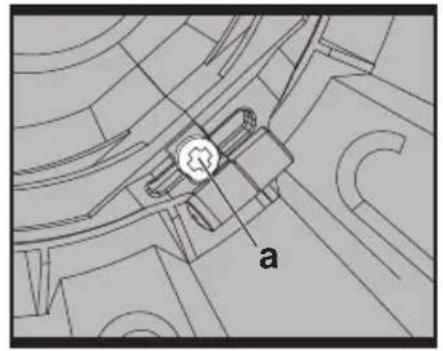
1. ASSEMBLY OF THE SAFETY GUARD (See Fig. A1, A2)
Fix the safety guard to the trimmer head making sure the sides are located into the grooves on the trimmer head.
Secure the safety guard onto the trimmer head with the screw (a) provided.
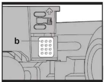
2. ASSEMBLE OF THE EDGER WHEEL (See Fig. B1, B2)
Insert the edger wheel onto grooves of cutting head. Make sure the groove of the wheel is locked in the metal plate.
Press the release button (b) on the wheel and pull out to take off the wheel.
OPERATION INSTRUCTIONS

WARNING! The charger and battery pack are specially designed to work together so do not attempt to use any other devices. Never insert or allow metallic objects into your charger or battery pack connections because of an electrical failure and hazard will occur.
INTENDED USE
The machine is intended for the cutting of grass and weeds under bushes, as well as on slopes and edges that can not be reached with the lawn mower.
1. BEFORE USING YOUR CORDLESS GRASS TRIMMER
Your battery pack is UNCHARGED and you must charge once before use.
The battery charger supplied is matched to the Li-lon battery installed in the machine. Do not use another battery charger.
The Li-Ion battery is protected against deep discharging. When the battery is empty, the machine is switched off by means of a protective circuit: The trimmer head no longer rotates.
In a warm environment or after heavy use, the battery pack may become too hot to permit charging. Allow time for the battery to cool
down before recharging.
3. TO REMOVE OR INSTALL BATTERY PACK (See Fig. C)
Depress the battery release button to release battery pack from your trimmer.
After recharging, insert the battery pack into trimmer's battery port. A simple push and slight pressure will be sufficient.
4. SAFETY ON/OFF SWITCH (See Fig. D)
Your switch is locked off to prevent accidental starting. Depress lock off button (c) then on/off switch (d) and release lock off button (c). Your switch is now on. To switch off, just release the on/off switch.

WARNING! The cutting head continues to rotate after the
trimmer has been switched off; wait until it has completely stopped then lay down the tool.
5. ADJUSTMENT OF THE TELESCOPIC SHAFT (See Fig. E)
Unscrew the lower locking knob (4) in the direction indicated to unlock.
Adjust the length of the telescopic shaft to the most comfortable length.
Tighten the lower locking knob.
6. MAIN HANDLE ROTATION (See Fig. F1, F2)
Holding the lower housing then pull upward the shaft, then rotate 90 degree clockwise (See Fig. F1), then release, the shaft will be locked in position automatically. (See Fig. F2)
7. ADJUSTMENT OF AUXILIARY HANDLE
Pull up the auxiliary handle locking lever (5).
Hold the lever and rotate the auxiliary handle to the most comfortable and balanced position (See Fig. G).
Release the lever, your auxiliary handle has been locked.
8. ADJUSTMENT OF THE TRIMMER HEAD ANGLE TO THE SHAFT
Adjust the trimmer head angle downwards, Put your one foot on the motor house, then grip the main handle, apply adequate force to adjust, as shown in Fig H1.
Adjust the trimmer head angle upwards, Put
your one foot on the safety guard, then grip the main handle, apply adequate force to adjust, as shown in Fig. H2.
9. SPACER GUARD
Push the spacer guard in and out into place before trimming, as shown in Fig. I. Make sure the spacer guard is locked firmly.
OPERATION
WARNING! Always wear the eye protection. Never lean over the trimmer head. Rocks or debris can ricochet or be thrown into eyes and face and cause blindness or other serious injury. When operating unit, check for the following:
Wear eye protection and heavy clothing. Hold front handle with one hand and auxiliary handle with the other hand. Keep unit below waist level. Work only from your right to your left to ensure debris is thrown away from you. Without bending over, keep line near and parallel to the ground (perpendicular when edging) and not crowded into material being cut. Make sure that line is fed out before operation. Make sure motor is up to full speed before trimming.
Use only 1.65mm cutting line, diameter line. Other sizes of line will not feed properly and will result in improper cutting head function or can cause serious injury. Do not use other material such as wire, string, rope, etc. Wire can break off during cutting and become a dangerous missile that can cause serious injury.
TRIMMING
Hold the bottom of the trimmer head about 8 cm above the ground and at an angle. Allow only the tip of line to make contact. Do not force trimmer line into work area.
EDGING (See Fig. J)
Holding the lower housing then pull upwards the shaft, then rotate 90 degree clockwise. (See Fig. F1)
Adjust trimmer head angle to be the lowest horizontal setting. Then position the wheel on the ground for edge mode. The guard has two white line guides to indicate the cutting line position. Align these marks with the edge of your lawn. While edging, allow the tip of the line to make contact. Do not force the line. The rotation wheel helps protect the unit and keeps the unit from contacting the ground. Take extra caution while edging as objects can be thrown from the trimmer line.
AUTOMATIC LINE FEED SYSTEM
When initially switching on the trimmer, a small length of line is fed out.
A 'clattering' noise will be heard when the lines hit the line cutter. DO NOT BE ALARMED this is quit normal. After about 5 seconds the line will be cut to the correct length and the noise will reduce as the motor receives full speed.
If the noise of the line being cut can't be heard, more line will be fed out.
To feed more line, it is first necessary to allow the trimmer to stop completely, then restart, allowing the motor to reach full speed.
Repeat above until you hear the lines hitting against the line cutter. (Do not repeat this procedure more than 6 times)
TO MANUALLY FEED THE LINE (See Fig. K1)
If required, line can be feed out manually.
To operate, press and release manual line feed button (16), while gently pulling out the line until the lines reach the line cutter.
If the line extends past the line cutter, too much line has been fed out.
If too much line is fed out, remove the spool cap and turn spool counter-clockwise until the line is at the desired length.
TO REMOVE THE CAP (See Fig. K2)
Press and hold in the two latches (12).
Pull cap away from the spool holder.
When refitting the spool cap.
Keep all areas of the cap and spool holder clean.
Replace the cap, pressing firmly down towards the spool holder to ensure cap is fully located.
Check that the cap is correctly fitted by trying to remove it without depressing the two latches.
TO REPLACE CUT LINE
For your convenience it is recommended you buy spool and line complete.
TO FIT SPOOL AND LINE COMPLETE:
Remove old spool.
Place new spool into cap with cut out areas of the spool in line with eyelet.
Release line from cleat and feed line through eyelet.
Refit the cap.
TO FIT NYLON LINE ONLY:
WARNING! Take approximately 3m of line. Insert 15mm of line into the spool holes and wind line in the direction of the arrows on the top of the spool. Your Trimmer is designed to use only line with a Maximum diameter of 1.65mm"
IMPORTANT: Leave approximately 4"
(100mm) of line unwound and place into cleat. Care should be taken to ensure that the line is neatly coiled on the spool. Failure to do so will impair the efficiency of the automatic line feed. Then fit spool as described in "To fit spool and line complete".
MAINTENANCE
After use, disconnect the battery from the mains and check for damage.
Your power tool requires no additional lubrication or maintenance. There are no user serviceable parts in your power tool. Never use water or chemical cleaners to clean your power tool. Wipe clean with a dry cloth. Always store your power tool in a dry place. Keep the motor ventilation slots clean. Keep all working controls free of dust.
ENVIRONMENTAL PROTECTION

This product has been marked with a symbol relating to removing electric and electronic waste. This means that product shall not be discarded with household waste but that it shall be returned to a collection system which conforms to the European Directive 2002/96/CE. It will then be recycled or dismantled in order to reduce the impact on the environment. Electric and electronic equipment can be hazardous for the environment and for human health since they contain hazardous substances.
DECLARATION OF CONFORMITY
We,
POSITEC Germany GmbH
Declare that the product,
Description WORX Cordless Lawn Trimmer/Lawn Edge Trimmer
Type WG155E (130-169-designation of machinery, representative of Cordless Grass Trimmer)
Function Cutting grass and weeds
Complies with the following Directives, Machinery Directive 2006/42/EC
Electromagnetic Compatibility Directive 2004/108/EC
RoHS Directive 2011/65/EU
Noise Emission in the Environment by Equipment for Use Outdoors Directive 2000/14/EC amended by 2005/88/EC.
- Conformity Assessment Procedure as per Annex VI
- Measured Sound Power Level 90.6dB(A)
- Declared Guaranteed Sound Power Level 94dB(A)
-The notified body involved
Name: Intertek Testing & Certification Ltd
Address: Davy Avenue, Knowlhill, Milton Keynes, MK5 8NL
Standards conform to:
EN 60745-1 EN 55014-1
EN 55014-2 EN 786
EN ISO 3744
The person authorized to compile the technical file,
Name: Russell Nicholson
Address: Positec Power Tools (Europe) Ltd, PO Box 152, Leeds, LS10 9DS, UK

2013/02/25
Leo Yue
POSITEC Quality Manager
Name: Intertek Testing & Certification Ltd Anschrift: Davy Avenue, Knowlhill, Milton Keynes, MK5 8NL
Normen:
EN 60745-1 EN 55014-1
EN 55014-2 EN 786
EN ISO 3744
Name: Russell Nicholson
Adresse: Positec Power Tools (Europe) Ltd, PO Box 152, Leeds, LS10 9DS, UK
$$ \text {ko.yue} $$
2013/02/25
Leo Yue
DÉCLARATION DE CONFORMITÉ
Nous,
POSITEC Germany GmbH
Directive RoHS 2011/65/EU
Nom: Intertek Testing & Certification Ltd
Adresse: Davy Avenue, Knowlhill, Milton Keynes, MK5 8NL
Standards conform to:
EN 60745-1 EN 55014-1
EN 55014-2 EN 786
EN ISO 3744
Ltd, PO Box 152, Leeds, LS10 9DS, UK
$$ \text {leo.yue} $$
2013/02/25
Leo Yue
Nome: Intertek Testing & Certification Ltd
Morada: Davy Avenue, Knowlhill, Milton
Keynes, MK5 8NL
Ltd, PO Box 152, Leeds, LS10 9DS, UK
$$ \text {leo.yue} $$
2013/02/25
Leo Yue
Gestor de Qualidade POSITEC
- HANDVAT ACHTER
- EXTRA HANDVAT
- TELESCOOPSTEEL
- VERGRENDELKNOP
- VERGRENDELKNOP EXTRA HANDGREEP
- BESCHERMKAP
- AFSTANDBESCHERMER
- WIEL VOOR KANTEN SNIJDEN
- DRAADSNIJDER
- ACCUPACK
- AFDEKKAP SNIJGEDEELTE (Zie Fig. K2)
- PAL VOOR LOSMAKEN AFDEKKAP (Zie Fig. K2)
- SPOEL (Zie Fig. K2)
- SNIJGEDEELTE (Zie Fig. K2)
- 00GJE (Zie Fig. K2)
- KNOP VOOR DRAADTOEVOER (Zie Fig. K1)
ALGEMENE VEILIGHEIDSWAARSCHUWINGEN VOOR VERMOGENSMACHINE

Naam: Intertek Testing & Certification Ltd Adres: Davy Avenue, Knowlhill, Milton Keynes, MK5 8NL
Standaards in overeenstemming met:
EN 60745-1 EN 55014-1
EN 55014-2 EN 786
EN ISO 3744
UDSKIFTNING AF SKÆRESNOR
2000/14/EC amended by 2005/88/EC.
- Konformitetstestprocedure Annex VI
- Målt niveau for lydeffekt 90.6dB(A)
- Deklareret garanteret niveau for lydeffekt 94dB(A)
- Afprøvningsorgan involveret
Navn: Intertek Testing & Certification Ltd
Adresse: Davy Avenue, Knowlhill, Milton Keynes, MK5 8NL
Standarder i overensstemmelse med:
EN 60745-1 EN 55014-1
EN 55014-2 EN 786
EN ISO 3744
Ltd, PO Box 152, Leeds, LS10 9DS, UK
2013/02/25
Leo Yue
Your switch is locked off to prevent accidental starting. Depress lock off button (c) then on/off switch (d) and release lock off button (c). Your switch is now on. To switch off just release the on/off switch

Unscrew the lower locking knob (4) in the direction indicated to unlock.
Adjust the length of the telescopic shaft to the most comfortable length.
Tighten the lower locking knob.
2000/14/EC amended by 2005/88/EC.
Nimi: Intertek Testing & Certification
Ltd
Osoite: Davy Avenue, Knowlhill, Milton
Keynes, MK5 8NL
Ltd, PO Box 152, Leeds, LS10 9DS, UK
$$ \text {ko.yue} $$
2013/02/25
Leo Yue
Å SETTE INN EN NY SKJÆRETRÅD.
Å SETTE INN NY TRÅD:

Navn: Intertek Testing & Certification Ltd
Adresse: Davy Avenue, Knowlhill, Milton Keynes, MK5 8NL
Standardene samsvarer med:
EN 60745-1 EN 55014-1
EN 55014-2 EN 786
EN ISO 3744
2000/14/EC amended by 2005/88/EC.
Adress: Davy Avenue, Knowlhill, Milton Keynes, MK5 8NL
Ltd, PO Box 152, Leeds, LS10 9DS, UK


2013/02/25
Leo Yue
Pull cap away from the spool holder
2000/14/EC amended by 2005/88/EC.
Adi: Intertek Testing & Certification Ltd
Adres: Davy Avenue, Knowlhill, Milton Keynes, MK5 8NL
PO Box 152, Leeds, LS10 9DS, UK
$$ \text {ko.yue} $$
2013/02/25
Leo Yue
2000/14/EC amended by 2005/88/EC.


- 20VMAX * LITHIUM
- TECHNICAL DATA
- NOISE INFORMATION
- This tool may cause hand-arm vibration syndrome if its use is not adequately managed.
- ACCESSORIES
- GENERAL POWER TOOL SAFETY WARNINGS
- Save all warnings and instructions for future reference.
- 1) WORK AREA SAFETY
- 2) ELECTRICAL SAFETY
- 3) PERSONAL SAFETY
- 4) POWER TOOL USE AND CARE
- SAFETY WARNINGS FOR LAWN TRIMMER
- SAFETY WARNINGS FOR BATTERY PACK
- SYMBOLS
- ASSEMBLY
- ASSEMBLY OF THE SAFETY GUARD (See Fig. A1, A2)
- ASSEMBLE OF THE EDGER WHEEL (See Fig. B1, B2)
- OPERATION INSTRUCTIONS
- INTENDED USE
- BEFORE USING YOUR CORDLESS GRASS TRIMMER
- TO REMOVE OR INSTALL BATTERY PACK (See Fig. C)
- SAFETY ON/OFF SWITCH (See Fig. D)
- ADJUSTMENT OF THE TELESCOPIC SHAFT (See Fig. E)
- MAIN HANDLE ROTATION (See Fig. F1, F2)
- ADJUSTMENT OF AUXILIARY HANDLE
- ADJUSTMENT OF THE TRIMMER HEAD ANGLE TO THE SHAFT
- SPACER GUARD
- OPERATION
- TRIMMING
- EDGING (See Fig. J)
- AUTOMATIC LINE FEED SYSTEM
- TO MANUALLY FEED THE LINE (See Fig. K1)
- TO REMOVE THE CAP (See Fig. K2)
- TO REPLACE CUT LINE
- TO FIT SPOOL AND LINE COMPLETE:
- TO FIT NYLON LINE ONLY:
- WARNING! Take approximately 3m of line. Insert 15mm of line into the spool holes and wind line in the direction of the arrows on the top of the spool. Your Trimmer is designed to use only line with a Maximum diameter of 1.65mm"
- MAINTENANCE
- After use, disconnect the battery from the mains and check for damage.
- ENVIRONMENTAL PROTECTION
- DECLARATION OF CONFORMITY
- Description WORX Cordless Lawn Trimmer/Lawn Edge Trimmer
- DÉCLARATION DE CONFORMITÉ
- ALGEMENE VEILIGHEIDSWAARSCHUWINGEN VOOR VERMOGENSMACHINE
- UDSKIFTNING AF SKÆRESNOR
- Å SETTE INN EN NY SKJÆRETRÅD.
- Å SETTE INN NY TRÅD:
Brand : WORX
Model : WG155E
Category : String Trimmer