
WG117 - String Trimmer WORX - Free user manual and instructions
Find the device manual for free WG117 WORX in PDF.


| Product Type | Electric Grass Trimmer |
| Brand | Worx |
| Model | WG117 |
| Power Source | Corded Electric |
| Rated Voltage | 220-240 V |
| Frequency | 50/60 Hz |
| Motor Power | 6.5 A |
| Cutting Width | 30 cm (12 in) |
| Cutting Type | Automatic Dual Line |
| Line Diameter | 2.0 mm |
| Weight | 2.4 kg |
| Power Cable Length | 30 m |
| Main Functions | Trimming, edging, adjustable head tilt |
| Maintenance and Cleaning | Clean after each use, check line regularly |
| Safety | Safety stop, eye protection recommended |
| Spare Parts and Repairability | Interchangeable cutting line, protective cover available |
| General Information | 2-year warranty, suitable for medium-sized gardens |
Frequently Asked Questions - WG117 WORX
User questions about WG117 WORX
0 question about this device. Answer the ones you know or ask your own.
Ask a new question about this device
Download the instructions for your String Trimmer in PDF format for free! Find your manual WG117 - WORX and take your electronic device back in hand. On this page are published all the documents necessary for the use of your device. WG117 by WORX.
USER MANUAL WG117 WORX
| 2-in-1 Grass Trimmer/Edger | EN | P06 |
| Coupe gazon/Taille-bordure 2 en 1 | F | P14 |
| 2 en 1 Cortadora de cesped/Ribeteadora | ES | P23 |

ABC1

C2DE1
E2E3E4
FGH1
H2IJ
KL1L2
L3L4
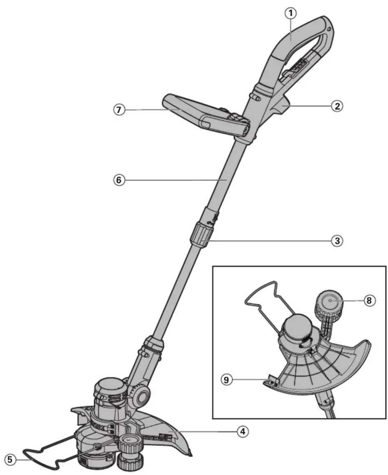
- REAR HANDLE
- PLUG INSERT
- LOCKING COLLAR
- SAFETY GUARD
- FLOWER GUARD
- TELESCOPIC SHAFT
- AUXILIARY HANDLE
- EDGER WHEEL
- LINE CUTTER
- CUTTING HEAD COVER (See Fig. K)
- CAP RELEASE LATCH (See Fig. K)
- SPOOL (See Fig. K)
- CUTTING HEAD (See Fig. K)
- EYELET (See Fig. K)
- LINE FEED BUTTON (See Fig. J)
Not all the accessories illustrated or described are included in standard delivery.
TECHNICAL DATA
| Rated voltage 120V~60Hz |
| Rated current 5A |
| No load speed 8000/min |
| Cutting diameter 14" |
| Line diameter 0.065" |
| Line length 2x16ft |
| Machine weight 6.2 lbs |
ACCESSORIES
Safety guard 1
Auxiliary handle 1
Edger wheel 1
Flower guard 1
Only use the appropriate accessories intended for this tool. Accessory information can be found on the product packaging, at a WORX dealer or on our website at www.worxtools.com.
SAFETY INSTRUCTIONS

WARNING! Some dust created by power sanding, sawing, grinding,
drilling and other construction activities contains chemicals known to the state of California to cause cancer, birth defects or other reproductive harm. Some examples of these chemicals are:
- Lead from lead-based paints;
- Crystalline silica from bricks and cement and other masonry products;
- Arsenic and chromium from chemically-treated lumber.
Your risk from these exposures varies, depending on how often you do this type of work. To reduce your exposure to these chemical:
• Work in a well ventilated area;
- Work with approved safety equipment, such as those dust masks that are specially designed to filter out microscopic particles.

WARNING! When using electric gardening appliances, basic safety
precautions must always be followed to reduce the risk of fire, electric shock, and serious injury, including the following:
READ ALL INSTRUCTIONS
1. FOR ALL DOUBLE-INSULATED APPLIANCES
a) Replacement parts.
When servicing, use only identical replacement parts.
b) Polarized appliance connections.
To reduce the risk of electric shock, this appliance has a polarized plug (one blade is wider than the other) and will require the use of a polarized extension cord. The appliance plug will fit into a polarized extension cord only one way. If the plug does not fit fully into the extension cord, reverse the plug. If the plug still does not fit, obtain a correct polarized extension cord. A polarized extension cord will require the use of a polarized wall outlet. This plug will fit into the polarized wall outlet only one way. If the plug does not fit fully into the wall outlet, reverse the plug. If the plug still does not fit, contact a qualified electrician to install the proper wall outlet. Do not change the equipment plug, extension cord receptacle, or extension cord plug in any way.
2. FOR ALL APPLIANCES
a) Avoid dangerous environment. Don't use appliances in damp or wet locations.
b) Don't use in rain.
c) Keep children away. All visitors should be kept at a distance from work area.
d) Dress properly. Do not wear loose clothing or jewelry. They can be caught in moving parts. Use of gloves and substantial footwear is recommended when working outdoors. Wear protective hair covering to contain long hair.
e) Use safety glasses. Always use eye protection plus a dust mask if operation is dusty.
f) Use right appliance. Do not use appliance for any job except that for which it is intended.
g) Ground Fault Circuit Interrupter (GFCI) protection should be provided on the circuit(s) or outlet(s) to be used for the gardening appliance.
Receptacles are available having built-in GFCI protection and may be used for this measure of safety.
h}

WARNING! To reduce the risk of electric shock, use only with an
extension cord intended for outdoor use, such as an extension cord of cord type SW-A, SOW-A, STW-A, STOW-A, SJW-A, SJOW-A, SJTW-A. or SJTOW-A.
i) Extension cord! Make sure your extension cord is in good condition. When using an extension cord, be sure to use one heavy enough to carry the current your product will draw. An undersized extension cord will cause a drop in line voltage resulting in loss of power and overheating. Table 1 shows the correct size to use depending on cord length and nameplate ampere rating. If in doubt, use the next heavier gauge. The smaller the gauge number, the heavier the cord. To reduce
the risk of disconnection of appliance cord from the extension cord during operating:
i) Make a knot as shown in Figure 1;
ii) Use one of the plug-receptacle retaining straps or connectors described in this manual.
Table 1 Minimum gauge for extension cords
| Volts Total | length of cord in feet | |||
| 120V 25 50 | 100 150 | |||
| 240V 50 100 | 200 300 | |||
| Ampere Rating More than Not more than | AWG | |||
| 0-6 18 16 | 6 12 | |||
| 6-10 | 18 | 16 | 14 | 12 |
| 10-12 | 16 | 16 | 14 | 12 |
| 12-16 | 14 12 | Not recommended | ||
NOTE-Only the applicable parts of the Table need to be included. For instance, a 120-volt product need not include the 240-volt heading.
Figure 1
METHOD OF SECURING EXTENSION
CORD
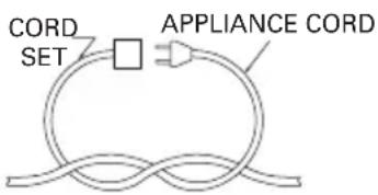
(A) TIE CORD AS SHOWN
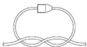
(B) CONNECT PLUG AND RECEPTACLE
j) Avoid unintentional starting. Don't carry plugged-in appliance with finger on switch. Be sure switch is off when plugging in.
k) Don't abuse cord. Never carry appliance by cord or yank it to disconnect from receptacle. Keep cord from heat, oil, and sharp edges.
I) Don't grasp the exposed cutting blades or cutting edges when picking up or holding the appliance.
m) Don't force appliance. It will do the job better and with less likelihood of a risk of injury at the rate for which it was designed.
n) Don't overreach. Keep proper footing and balance at all times.
o) Stay alert. Watch what you are doing. Use common sense. Do not operate appliance when you are tired.
p) Disconnect appliance. Disconnect the appliance from the power supply when not in use, before servicing, when changing accessories such as blades, and the like.
q) Store idle appliances indoors. When not in use, appliances should be stored indoors in dry, and high or locked-up place, out of reach of children.
r) Maintain appliance with care. Keep cutting edge sharp and clean for best performance and to reduce the risk of injury. Follow instructions for lubricating and changing accessories. Inspect appliance cord periodically, and if damaged, have it repaired by an authorized service facility. Inspect extension cords periodically and replace if damaged. Keep handles dry, clean, and free from oil and grease.
s) Check damaged parts. Before further use of the appliance, a guard or other part that is damaged, the tool should be carefully checked to determine that it will operate properly and perform its intended function. Check for alignment of moving parts, binding of moving parts, breakage of parts, mounting, and any other condition that may affect its operation. A guard or other part that is damaged should be properly repaired or replaced by an authorized service center unless indicated elsewhere in this manual.
3. EDGER-TRIMMERS
a) Keep guards in place and in working order.
b) Keep blades sharp.
c) Keep hands and feet away from cutting area.
4. CULTIVATORS, GRASS SHEARS a) Keep hands away from blades.
Save these instructions.
SYMBOLS
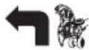
edging
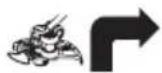
Trimming
ASSEMBLY
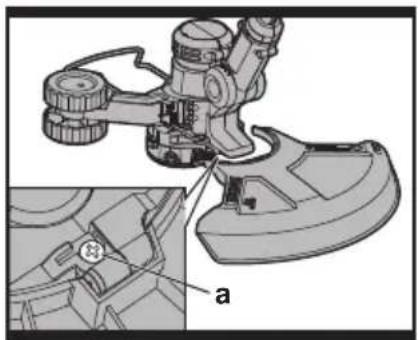
1. ASSEMBLY OF THE SAFETY GUARD (See Fig. A)
Remove the screw from the Safety Guard (4) and fit the guard to the trimmer head; align the guard so it slides into the slots located on the trimmer head. Turn the tool over and secure the Safety Guard onto the trimmer head with the screw (a) provided.
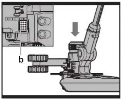
2. ASSEMBLY OF THE EDGER WHEEL (See Fig. B)
With the tool right side up, slide the Edger Wheel (8) assembly onto the metal plate located on the side of the trimmer head. Make sure the grooves of the Edger Wheel assembly lock onto the metal plate; you will hear it click into place.
To remove the wheel assembly, press the release button (b) on the wheel and pull the wheel assembly upward.
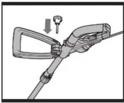
3. FITTING THE AUXILIARY HANDLE (See Fig. C1,C2)
NOTE: THE AUXILIARY HANDLE MUST BE ATTACHED to the trimmer shaft before use.

WARNING: To avoid injury, ALWAYS turn off and disconnect the
trimmer from the power outlet BEFORE installing parts or cleaning the trimmer or making any adjustments.
1) Disconnect the trimmer from the power supply.
2) Unscrew the auxiliary handle's tightening knob (counter-clockwise) and remove from handle.
3) Position auxiliary handle onto handle bracket assembly located on trimmer's top-shaft (See Fig. C1).
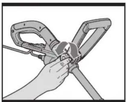
4) Position the knob and screw through the auxiliary handle and bracket, and tighten knob (turn clockwise). (See Fig. C2) Do not tighten completely until you have adjusted the auxiliary handle to your desired working position.
OPERATING INSTRUCTIONS

WARNING: The cutting head continues to rotate after the
trimmer has been switched off. Wait until it stops before laying the trimmer down.
- Always wear eye protection. Never lean over the trimmer head. Rocks or debris can ricochet or be thrown into the eyes and face and cause blindness or other serious injury.
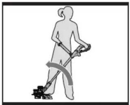
- Hold front handle with one hand and auxiliary handle with the other hand. Keep unit below waist level. Work only from your right to your left to ensure debris is thrown away from you. Without bending over, keep line near and parallel to the ground (perpendicular when edging) and not crowded into material being cut.
- Before operating, make sure both trimmer lines are extended. When trimming, make sure motor is running at full speed.
- Use only 0.065"(1.65mm) diameter cutting line. Other line sizes will not properly feed in the trimmer head and could cause serious injury. Never use other materials such as wires, string or rope, as this may break off during cutting and cause serious injury.
1. FLOWER GUARD (See Fig. D)
Push the Flower Guard (5) in when edging and pull it out before trimming, as shown in Fig D. Before trimming or edging make sure the Flower Guard is locked firmly in position.
2. ADJUSTMENT OF THE TELESCOPIC SHAFT (See Fig. E1,E2)
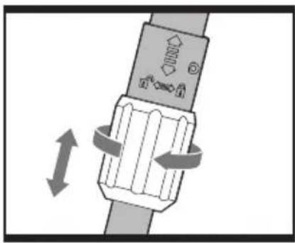
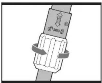
Unscrew the Locking Collar (3) clockwise to unlock, as indicated. Adjust the length of the Telescopic Shaft (6) to the most comfortable length (See Fig. E1). Tighten the Locking Collar counter-clockwise to lock, as indicated (See Fig. E2).
3. MAIN HANDLE ROTATION
(See Fig. E3,E4)
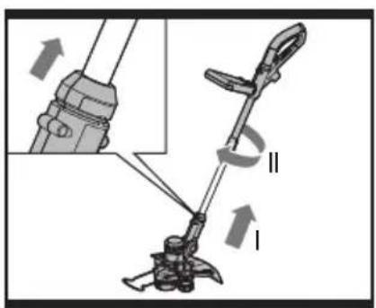
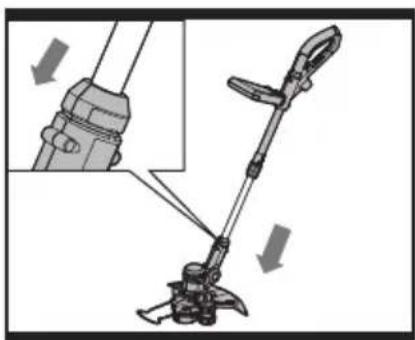
First, hold down the lower housing with your
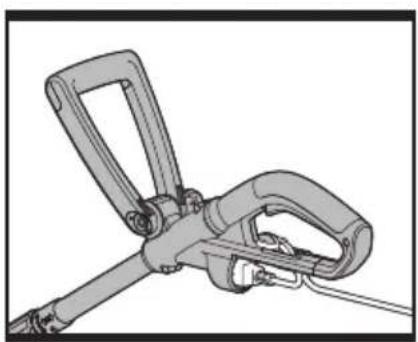
foot and pull upward on the Telescopic Shaft (6). Then rotate the Telescopic Shaft clockwise 90 degrees (See Fig. E3) and release; the Shaft will be locked in position automatically (See Fig. E4).
4. ADJUSTING THE AUXILIARY HANDLE (See Fig. F)
1) The auxiliary handle's bracket can be moved up or down on the shaft and the auxiliary handle itself can be moved forward or backward into 4 different locked positions (See Fig. F).
2) When the handle is in desired position, turn knob and tighten securely.
5. ATTACHING EXTENSION CORD (See Fig. G)
An extension cord retainer is built into the Rear Handle (1) that prevents the cord from coming unplugged. To use this feature, simply double the extension cord about 8 inches (203mm) from the end, forming a small loop. Insert this loop into the slot on the back of the handle. Hook the end of the loop over the tab. Gently tug on the cord to insure that it is firmly retained in the trimmer's handle. Plug the receptacle end of the extension cord into the Plug Insert (3) in the trimmer.
6. ADJUSTMENT OF TRIMMER HEAD ANGLE (See Fig. H1,H2)
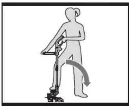
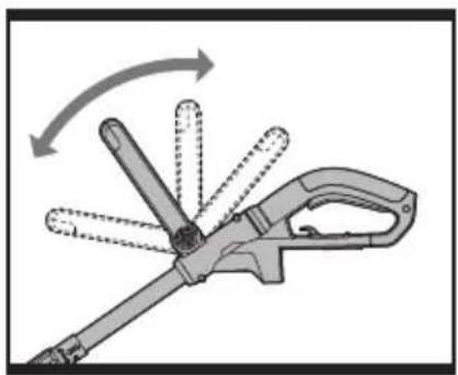
To adjust the trimmer head angle downwards, put one foot on the motor housing, then grip the Rear Auxiliary handles, and apply adequate force to adjust, as shown in Fig. H1. To adjust the trimmer head angle upwards, put one foot on the Safety Guard (4), then grip the Rear and Auxiliary handles and apply adequate force to adjust, as shown in Fig. H2.
7. USING THE ON/OFF TRIGGER
Press and hold the on/off trigger to start the trimmer. Release to stop.
8. TRIMMING
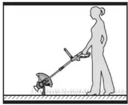
Hold the bottom of the trimmer head just above the ground and at a slight angle. Allow only the tip of line to make contact with the grass. Let the trimmer line work at its own pace; do not force the trimmer line into the work area.
9. EDGING
First, rotate the Rear Handle (1) 90 degree clockwise (See "Main Handle Rotation", Fig. E3 & E4).
Adjust the trimmer head angle to be the lowest horizontal setting (See “Adjust the trimmer head angle to the lowest horizontal setting”, Fig. H1). Then position the Edger Wheel (8) on the ground for edge mode (See Fig. I). There are two white lines, located on each end of the Safety Guard (4), that show the cutting plane of the trimmer line. Align these marks with the edge of your lawn.
While edging, allow the tip of the line to make contact. Do not force the line. The wheel helps to prevent the unit from touching the ground. Take extra caution while edging as objects can be thrown from the trimmer line.
10. AUTOMATIC LINE FEED SYSTEM
When initially switching on the trimmer, a small length of line is fed out.
A ‘clattering’ noise will be heard for a short time. This is normal and is caused by the line being cut by the line cutter. Once the line is cut to the correct length, the ‘clattering’ noise will stop and the trimmer motor will run at full speed.
To feed more line, stop the trimmer completely, then restart, allowing the motor to reach full speed. Repeat this until you hear the 'clattering' noise of the line cutting. (Do not repeat this procedure more than 6 times)
11. MANUALLY FEEDING THE LINE (See Fig. J)
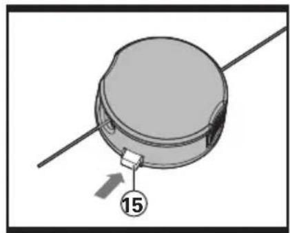
Press and release the Line Feed Button (15) (See Fig. J) whilst gently pulling out on one of the lines until it has reached the line cutter. When the required amount of line is fed out, gently pull on the second line (there is no need to press the Line Feed Button again). If the line extends past the line cutter, too much line has been fed out.
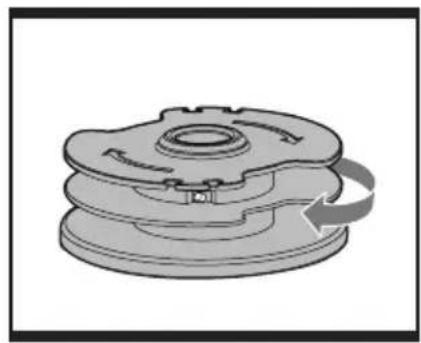
If too much line is fed out, remove the spool cap and click the spool counter-clockwise until the line is at the desired length.
12. REMOVING THE CAP
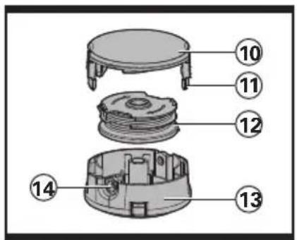
Press and hold in the two Cap Release Latches (11) (See Fig. K).
Pull the Cutting Head Cover (10) away from the Cutting Head (13). Keep the Cutting Head Cover and the inside of the Cutting Head clean from debris. To replace the Cutting Head Cover, press it firmly onto the spool holder. Ensure that it is correctly connected by trying to remove it without depressing the two Cap Release Latches.
13. CHANGING THE LINE SPOOL
First take off the Cutting Head Cover (10) and remove the old Spool (12). Place the new Spool onto the Cutting Head (13). Feed one line through the Eyelet (14), and then repeat for the second line. Reattach the Cutting Head Cover.

WARNING! Your Trimmer is
designed to only use line with a maximum diameter of 0.065" (1.65mm).
Only use nylon line.
IMPORTANT - Always wind the line onto the upper section of the spool first.
14. TO MANUALLY WIND LINE
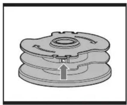
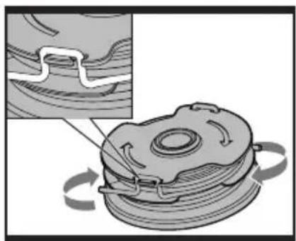
Take approximately 16ft (5m) of line and insert 5/8" (15mm) of line into one of the holes in the upper section of the Spool (12) (See Fig. L1). Wind the line in the direction of the arrows on the top of the Spool. Repeat process with separate piece of line on lower section of Spool (See Fig. L2&L3).
Leave approximately 4" (100mm) of line unwound and place it into the cleat. Repeat on the lower section of the Spool.
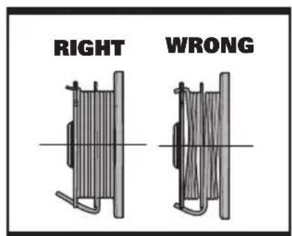
Care should be taken to ensure that the line is neatly coiled on the Spool (See Fig. L4).
Failure to do so will impair the efficiency of the automatic line feed.
Then fit the Spool as described above in
"Changing the Line Spool".
MAINTENANCE
After use, disconnect the machine from the electrical outlet and check for damage.
Your trimmer requires no additional lubrication or maintenance. There are no user serviceable parts in your trimmer. Electric powered trimmers should only be repaired by an authorized repairer. Use only WORX replacement parts and accessories.
Never use water or chemical cleaners to clean your trimmer. Wipe clean with a dry cloth.
Always store your trimmer in a dry place out of the reach of children. Keep the motor ventilation slots clean. If you see some sparks flashing in the ventilation slots, this is normal and will not damage your trimmer.
- POIGNÉE ARRIÈRE
- PRISE
- BOUTON INFÉRIEUR D'AJUSTEMENT
- DÉGAGEMENT DE POIGNÉE
- DÉFLECTEUR DE PROTECTION DES FLEURS
- MANCHE TÉLESCOPIQUE
- GARDE DE SÉCURITÉ
- ROUE DE COUPE-BORDURES
- COUPEUR DE CORDON DE COUPE
- COUVERCLE DE LA TÊTE DE COUPE (Voir Fig. K)
- MÉCANISME DE DÉVERROUILLAGE DU COUVERCLE (Voir Fig. K)
- BOBINE (Voir Fig. K)
- TÊTE DE COUPE (Voir Fig. K)
- OEILLET (Voir Fig. K)
- BOUTON D'ALIMENTATION DU CORDON DE COUPE (Voir Fig. J)
(B) CONECTE EL ENCHUFE Y EL RECEPTÁCULO
Copyright © 2012, Positec. All Rights Reserved.





- TECHNICAL DATA
- ACCESSORIES
- SAFETY INSTRUCTIONS
- WARNING! SOME DUST CREATED BY POWER SANDING, SAWING, GRINDING
- DRILLING AND OTHER CONSTRUCTION ACTIVITIES CONTAINS CHEMICALS KNOWN TO THE STATE OF CALIFORNIA TO CAUSE CANCER, BIRTH DEFECTS OR OTHER REPRODUCTIVE HARM. SOME EXAMPLES OF THESE CHEMICALS ARE
- WARNING! WHEN USING ELECTRIC GARDENING APPLIANCES, BASIC SAFETY
- PRECAUTIONS MUST ALWAYS BE FOLLOWED TO REDUCE THE RISK OF FIRE, ELECTRIC SHOCK, AND SERIOUS INJURY, INCLUDING THE FOLLOWING
- READ ALL INSTRUCTIONS
- FOR ALL DOUBLE-INSULATED APPLIANCES
- REPLACEMENT PARTS
- POLARIZED APPLIANCE CONNECTIONS
- FOR ALL APPLIANCES
- EDGER-TRIMMERS
- CULTIVATORS, GRASS SHEARS A) KEEP HANDS AWAY FROM BLADES
- SYMBOLS
- ASSEMBLY
- ASSEMBLY OF THE SAFETY GUARD (SEE FIG. A)
- ASSEMBLY OF THE EDGER WHEEL (SEE FIG. B)
- FITTING THE AUXILIARY HANDLE (SEE FIG. C1,C2)
- OPERATING INSTRUCTIONS
- FLOWER GUARD (SEE FIG. D)
- ADJUSTMENT OF THE TELESCOPIC SHAFT (SEE FIG. E1,E2)
- MAIN HANDLE ROTATION
- ADJUSTING THE AUXILIARY HANDLE (SEE FIG. F)
- ATTACHING EXTENSION CORD (SEE FIG. G)
- ADJUSTMENT OF TRIMMER HEAD ANGLE (SEE FIG. H1,H2)
- USING THE ON/OFF TRIGGER
- TRIMMING
- EDGING
- AUTOMATIC LINE FEED SYSTEM
- MANUALLY FEEDING THE LINE (SEE FIG. J)
- REMOVING THE CAP
- CHANGING THE LINE SPOOL
- WARNING! YOUR TRIMMER IS
- TO MANUALLY WIND LINE
- MAINTENANCE
Brand : WORX
Model : WG117
Category : String Trimmer