
DH 62 - Humidifier Master - Free user manual and instructions
Find the device manual for free DH 62 Master in PDF.
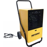
| Product type | Dehumidifier |
| Brand | Master |
| Model | DH 62 |
| Power supply | ~220-240 V, 50 Hz, 890 W, 4.4 A |
| Dehumidification capacity | 52 liters per 24 hours |
| Airflow | 480 m³/h |
| Relative humidity range | 30 to 98 % RH |
| Operating temperature range | 1 to 32 °C |
| Refrigerant | R1234yf, 340 g |
| Noise level | 53 dB(A) |
| Condensate tank | 12 liters |
| Weight | 47 kg |
| Continuous drainage connection | Yes, 16 mm diameter |
| Condensate pump | Optional |
| Air filter | Washable, monthly cleaning recommended |
| Defrost | Automatic hot gas |
| Safety | Automatic tank full shutoff, antifreeze protection, alarms |
| Spare parts | Originals recommended |
Frequently Asked Questions - DH 62 Master
User questions about DH 62 Master
0 question about this device. Answer the ones you know or ask your own.
Ask a new question about this device
Download the instructions for your Humidifier in PDF format for free! Find your manual DH 62 - Master and take your electronic device back in hand. On this page are published all the documents necessary for the use of your device. DH 62 by Master.
USER MANUAL DH 62 Master
natural_image
Icon of an open book with an exclamation mark, enclosed in a diamond shape with a yellow diagonal stripe (no text or symbols)USER AND MAINTENANCE MANUAL
| (1W3Y) | IMPORTANT: In order to have a correct function you must use an electrical generator in class G3 or more (frequency variation ±1%, tension variation ±2%). The maximum power of electrical generator must be three time the nominal power of device that you must connect. |
| MODEL | DH 44DV DH 62DV | |
 | 30 ÷ 98 % 30 ÷ 98 % | |
 | 1 ÷ 32 ^ 1 ÷ 32 ^ | |
 | 480 m^3/h-m^3/ч 480 m^3/h-m^3/ч | |
 | 41 l-l / 24 h-ч 52 l-l / 24 h-ч | |
 | R1234yf / 365 g-rGWP-Потенциал глобального потепления 4 | R1234yf / 340 g-rGWP-Потенциал глобального потепления 4 |
 | ~220-240 V-B50 Hz-Гц610 W-Bт / 3,1 A | ~220-240 V-B50 Hz-Гц890 W-Bт / 4,4 A |
| ~110-120 V-B50 Hz-Гц610 W-Bт / 6,2 A | ~110-120 V-B50 Hz-Гц890 W-Bт / 8,8 A | |
| dB(A) | 53 dB-дБ 53 dB-дБ | |
 | 12 l-l 12 l-l | |
 | 46 kg-кг 50 kg-кг | |
 | 2,6 mPaLRA 16 A (220-240 V-B)LRA 32 A (110-120 V-B) | 2,6 mPaLRA 21,6 A (220-240 V-B)LRA 43,2 A (110-120 V-B) |
| CO2Eq | 1,5 1,4 | |
| GWP | 4 | 4 |
 | IMPORTANT: In order to have a correct function you must use an electrical generator in class G3 or more (frequency variation ±1%, tension variation ±2%). The maximum power of electrical generator must be three time the nominal power of device that you must connect. |
IMPORTANT: In order to have a correct function you must use an electrical generator in class G3 or more (frequency variation ±1%, tension variation ±2%). The maximum power of electrical generator must be three time the nominal power of device that you must connect.
PICTURES - FIGURE - ABBILDUNGEN - FIGURAS - FIGURES - FIGUREN - FIGU- RAS - FIGURER - KUVAT - FIGURER - FIGURER - ILUSTRACJE - ИЛЛЮСТРАЦИИ - OBRÁZKY - ÁBRÁK - SLIKE - ŞEKİLLER - SLIKE - ILIUSTRACIJOS - ATTĚLI - JOONISED - IMAGINI - OBRÁZKY - CXEMI - МАЛЮНКИ - SLIKE - EIKONEΣ - 图示 - СУРЕТТЕМЕЛЕР
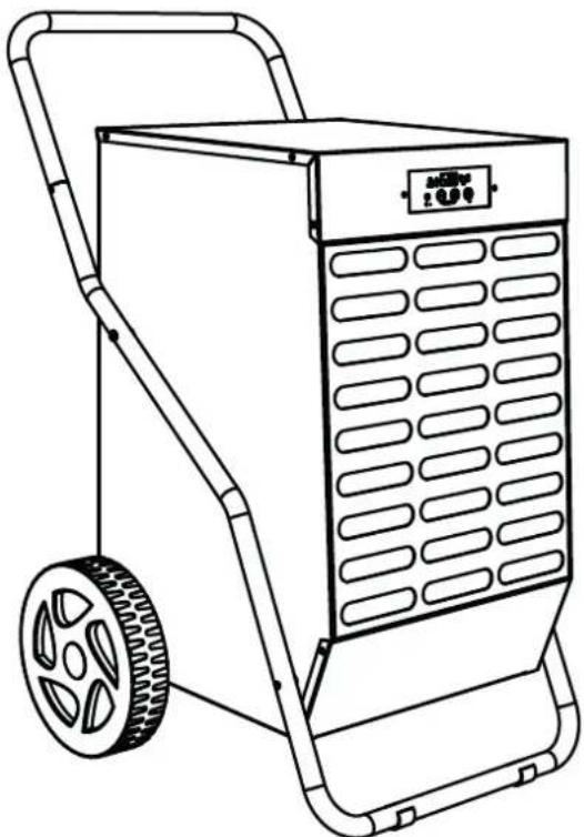
DH 26
natural_image
Line drawing of a portable industrial machine with wheels and control panel (no text or symbols)DH 44
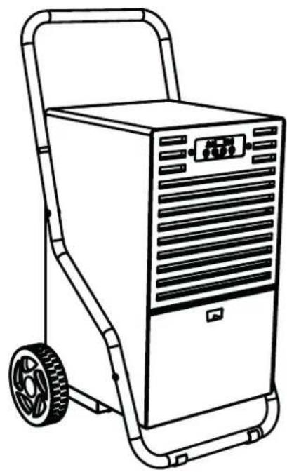
DH 62
DH 92
DH 100
natural_image
Line drawing of a portable industrial cart with wheels and control panel (no text or symbols)PICTURES - FIGURE - ABBILDUNGEN - FIGURAS - FIGURES - FIGUREN - FIGU- RAS - FIGURER - KUVAT - FIGURER - FIGURER - ILUSTRACJE - ИЛЛЮСТРАЦИИ - OBRÁZKY - ÁBRÁK - SLIKE - ŞEKİLLER - SLIKE - ILIUSTRACIJOS - ATTĚLI - JOONISED - IMAGINI - OBRÁZKY - CXEMI - МАЛЮНКИ - SLIKE - EIKONEΣ - 图示 - СУРЕТТЕМЕЛЕР
flowchart
graph TD
    A["Raw Material Input"] --> B["1"]
    B --> C["2"]
    C --> D["3"]
    D --> E["4"]
    E --> F["5"]
    F --> G["6"]
    style A fill:#f9f,stroke:#333
    style G fill:#bbf,stroke:#333

natural_image
Technical line drawing of a mechanical device with wheels and a grid-patterned panel (no text or symbols)PICTURES - FIGURE - ABBILDUNGEN - FIGURAS - FIGURES - FIGUREN - FIGU- RAS - FIGURER - KUVAT - FIGURER - FIGURER - ILUSTRACJE - ИЛЛЮСТРАЦИИ - OBRÁZKY - ÁBRÁK - SLIKE - ŞEKİLLER - SLIKE - ILIUSTRACIJOS - ATTĚLI - JOONISED - IMAGINI - OBRÁZKY - CXEMI - МАЛЮНКИ - SLIKE - EIKONEΣ - 图示 - СУРЕТТЕМЕЛЕР
PICTURES - FIGURE - ABBILDUNGEN - FIGURAS - FIGURES - FIGUREN - FIGU- RAS - FIGURER - KUVAT - FIGURER - FIGURER - ILUSTRACJE - ИЛЛЮСТРАЦИИ - OBRÁZKY - ÁBRÁK - SLIKE - ŞEKİLLER - SLIKE - ILIUSTRACIJOS - ATTĚLI - JOONISED - IMAGINI - OBRÁZKY - CXEMI - МАЛЮНКИ - SLIKE - EIKONEΣ - 图示 - СУРЕТТЕМЕЛЕР
natural_image
Mechanical assembly diagram showing two tires connected to a central shaft with a valve, no text or symbols present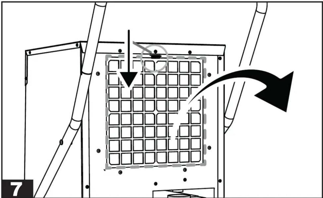
natural_image
Diagram of a mechanical or electrical component with grid pattern and directional arrows, no readable text or symbols present.| INDEX INDEX | |
| 1... INTRODUCTION | |
| 2... GENERAL DESCRIPTION OF THE UNIT | |
| 3... PRELIMINARY OPERATIONS | |
| 4... START-UP | |
| 5... MAINTENANCE | |
| 6... ALARM LIST |
▶▶▶1. INTRODUCTION
▶▶1.1. INTRODUCTION
The manual is intended for the end user only in regard to operations that can be performed with closed panels. The operations that require to open doors or panels with tools must only be performed by expert personnel. Each appliance must be connected to the power supply via a cable with a power plug supplied with the unit. For maintenance operations, the power plug must always be disconnected to allow the operator to intervene in safe conditions.
If assistance or spare parts are required, read the identification plate located outside of the unit to identify the appliance (model and serial number).
▶▶1.2. GENERAL SAFETY RULES
The purpose of the manual and of the entire documentation supplied is to allow both the installer and operator to correctly perform the installation, start-up and maintenance of the equipment, without causing damage to the personnel in charge and to the unit.
Each appliance is subject to a risk assessment carried out in compliance with current legislation, which defines the necessary actions and implements the protective measures required to achieve the risk reduction objectives.
All activities regarding the operation and maintenance of the unit must be performed:
▶ Only by properly trained people, who must implement safe working practices and use the personal protective equipment appropriate to the specific task performed, based on their specific qualification.
▶ Only by properly trained people who have read and fully understood the manuals, technical documents and safety documents.
▶ Use of the appliance must not be allowed to anyone who is not adequately trained and skilled.
This manual, the technical documents and any security documents attached must be read and stored for the entire lifespan of the appliance:
CAUTION: This appliance is designed for use in an indoor environment.
⚠️ CAUTION: The unit must be connected to an electrical system that complies with local electrical safety regulations.
⚠️ CAUTION: The unit must be placed by following the dimensions and spaces required, including the minimum spaces allowed by adjacent structures.
CAUTION: This equipment must always be connected to earth. We decline any liability for any danger or damage caused if this requirement is not complied with.
CAUTION: Sharp tools (screwdrivers, needles or the like) must not be inserted into the grids or inside any other panel opening, especially when the unit is open to remove the filter.
CAUTION: All maintenance and cleaning operations on the unit must be performed with the power supply disconnected. Never remove the front grille or open any part of the unit without first disconnecting the plug from the socket.
CAUTION: Do not use water to clean the unit. Use a wet cloth to clean the unit.
Never spray water on the unit and its electrical components.
The equipment must always be kept in a vertical position in order to prevent accidental spillage of condensation (water) from the specific container. It is strictly forbidden to move the equipment while connected to the power outlet, as the resulting vibrations and movements may cause the condensation to leak from the specific container, thus affecting the electrical parts.
The unit can only be moved after emptying the condensate tank, and in any case, it is ALWAYS REQUIRED to remove the plug from the socket before moving the appliance. Should water be accidentally spilled on the appliance, the unit must be immediately turned off and disconnected from the power supply, and may only be turned on after eight hours have elapsed.
CAUTION: The equipment contains R1234yf refrigerant: this gas is flammable. The amount of charge is indicated in the data table of this user manual.
Warning, the refrigerant is odourless.
Do not use any means to accelerate the defrosting process or for cleaning other than those recommended by the manufacturer.
The appliance must be placed in a room that does not have ignition sources continuously in operation (e.g. open flames, a gas appliance while running or an electric heater running).
Do not drill holes into or burn the appliance.
▶▶1.3. PERSONAL PROTECTIVE EQUIPMENT
Use the following personal protective equipment during unit use and maintenance operations:
⚠️ CLOTHING: Those who carry out maintenance or work on the unit in environments with slippery floors must wear safety shoes with non-slip soles.
⚠️ GLOVES: Appropriate gloves must be worn during cleaning and maintenance operations. When refilling the refrigerant gas, the use of appropriate gloves is mandatory in order to prevent the risk of freezing.
⚠️ MASK AND GOGGLES: Masks to protect the respiratory tract and safety goggles to protect the eyes must be worn during cleaning and maintenance operations.
▶▶1.4. GENERAL SAFETY RULES
The following safety signs, which must be respected, are affixed on the unit:

Read the user manual.
Read the technical manual.

Electric shock hazard.

Flammable material hazard.

CAUTION: It is strictly forbidden to re-ve the safety signs on the units.
▶▶▶2. GENERAL DESCRIPTION OF THE UNIT
(FIG. 1)
The dehumidifier is an appliance suitable for controlling the humidity of the room it is placed in. Dehumidification is carried out via a refrigeration cycle which is based on the physical
principle whereby the air, when it comes into contact with a cold surface, wets it, releasing humidity in the form of condensation drops.
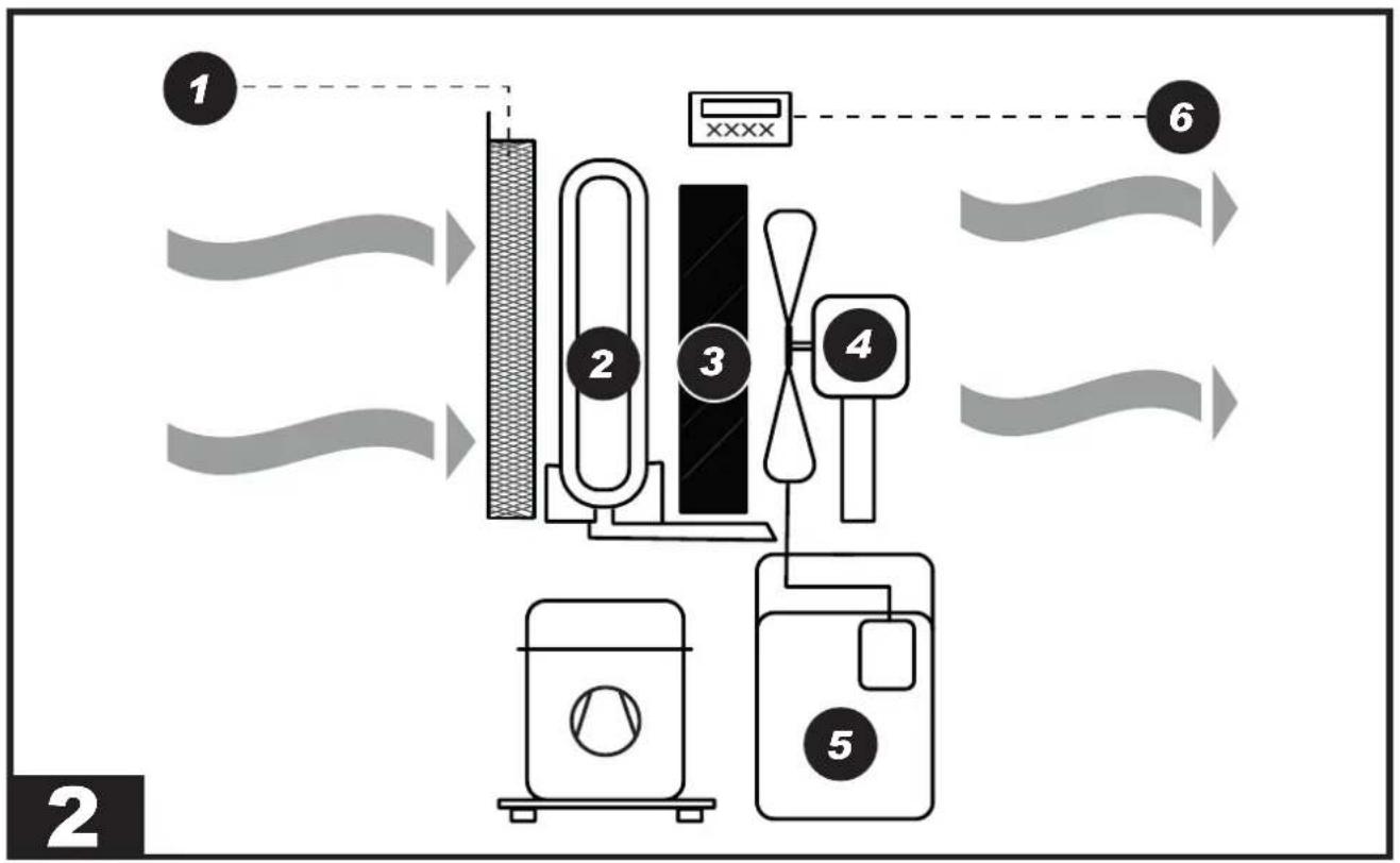
The equipment is made up as follows (FIG. 2): Air is extracted from the appliance: it passes through the washable filter (1), the aluminium coil (evaporator) (2), the hot exchanger (condenser) (3), the fan (4) and finally the dehumidified air flows out and is recirculated into the room through the grille. The condensed water is collected in the tank (5). A micro-switch stops the appliance when water in the tank reaches a certain level. An electronic board (6) manages the correct operation of the appliance.
This appliance is equipped with a hot gas defrost system, which ensures the correct operation of the dehumidifier within the temperature and humidity range specified in the technical data table.
▶▶2.1. REFRIGERANT CIRCUIT
The refrigerant gas used in these units is R1234yf. The refrigerant circuit is built in compliance with current standards.

Flammable material hazard.
This unit is hermetically sealed and contains fluorinated gas R1234yf GWP (R1234yf) = 4.
▶▶▶3. PRELIMINARY OPERATIONS
▶▶3.1. REMOVAL OF THE PACKAGING AND ASSEMBLY
Remove the packaging taking care not to damage the unit. Dispose of the packaging products (wood, plastic, cardboard), taking them to the specialised collection or recycling centres (follow the local regulations in force).
⚠️ CAUTION: Depending on the model, assemble the appliance, with any handles, wheels and all relevant hardware (FIG. 3) housed inside the packaging before commissioning.
▶▶3.2. INSPECTION
All units are factory assembled and wired (except for certain components). Upon receiving the unit, it must be immediately and thoroughly inspected, checking that it has not been damaged during transport or that no parts are missing.
⚠️ Before use, specifically check for any dents on the external metal panels, including those in the tank compartment. Also check that the cable, plug and relevant insulation are intact. Otherwise, it is FORBIDDEN to connect and start the unit, which must be sent to an authorised service centre.
▶▶3.3. OPERATING PRINCIPLES
⚠️ CAUTION: To ensure correct operation of the appliance, it is recommended to operate the unit within the limits shown on the technical data table.
▶▶3.4. POSITIONING
Set up the appliance to ensure an adequate air flow.
⚠️ CAUTION: Make sure that the appliance is placed in such a way so as to prevent contact with water.
▶▶3.5. SERVICE AREA
The hot air expelled by the fan must not be obstructed. Avoid hot air recirculation between suction and delivery to prevent compromising the performance of the unit or even interrupting normal operation.
⚠️ CAUTION: The equipment must not be placed in cramped environments, which do not allow adequate distribution of the air from the air outlet grille into the room.
⚠️ CAUTION: Do not place or hang objects on the front panel, it may cause damage to the unit.
▶▶3.6. GENERAL INFORMATION
⚠️ CAUTION: Disconnect the power plug from the socket before carrying out any maintenance operation on the electrical part.
CAUTION: Check that the supply voltage corresponds to the unit's operating data (voltage and frequency) shown on the data plate on the dehumidifier. The appliance is fitted with a power cable for correct operation.
⚠️ CAUTION: The earthing connection is mandatory.
▶▶▶4. START-UP
▶▶4.1. PRELIMINARY CHECKS
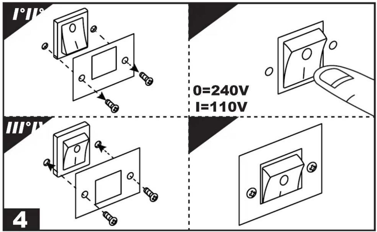
IMPORTANT: For dual voltage models (...DV), check the position of the transformer switch (220-240V / 110-120V). If the set voltage does not match that supplied by the mains, the voltage must be adapted (FIG. 4). Loosen the two lid screw fasteners, shift/press the switch onto the voltage value supplied and mount the lid again.
CAUTION: Check that the power cord is properly connected.
CAUTION: Check that all the cover panels are in the correct position and are locked via fixing screws before commissioning.
CAUTION: Always disconnect the power supply if the appliance is not used for a long period of time.
▶▶4.2. CONTROL PANEL
(FIG. 5)
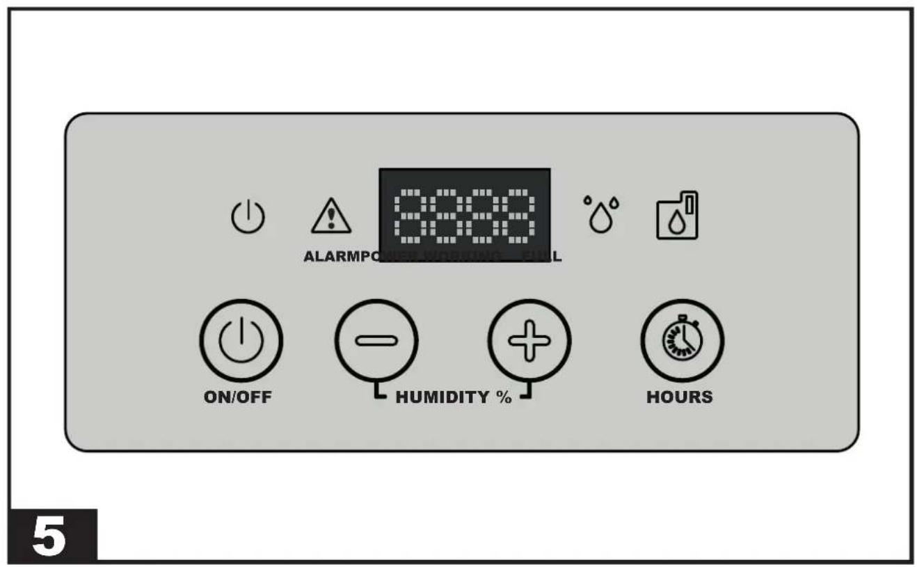
The units are equipped with a luminous signalling panel that indicates their operating status. A brief description of their meaning is provided below.
CONTROL PANEL:
LED:
▶ POWER LED: This LED is on if the unit is in the “ON” status, but in stand-by mode (i.e. the compressor is off).
▶ ALARM LED: This LED is on when the unit is in alarm. The display will show the error message.
▶WORKING LED: This LED is on when the compressor is running. The LED flashes when the dehumidifier is waiting to restart or is in defrost mode. The LED turns off when the desired amount of humidity has been reached in the “ON” status.
▶FULL LED: This LED is on when the condensate tank is full or if the pump is in alarm.
BUTTONS:
▶ ON/OFF: To turn on the dehumidifier, simply press the “ON/OFF” button. Based on the relative humidity set, the appliance starts working. When the room humidity reaches the required level, the appliance goes into stand-by mode and the unit stops, but remains in the “ON” status (POWER LED on). If the room humidity rises again, exceeding the previous set point, the dehumidifier re-starts again.
Press the “ON/OFF” button to turn off the appliance (with the appliance off, the display continues to indicate the relative humidity in the environment).
▶“-” / “+” (HUMIDITY SET): Press the “-” / “+” buttons to set the relative humidity desired. The display will start flashing, showing the new reference set point. After a few seconds the display stops flashing and the new humidity set point has been detected by the electronics.
It is possible to operate the appliance regardless of the degree of humidity present in the environment. By pressing the “-” button until the “CONT” message appears on the display, the appliance will operate continuously.
▶ HOURS: Press the “HOURS” button to view the working hours of the appliance.
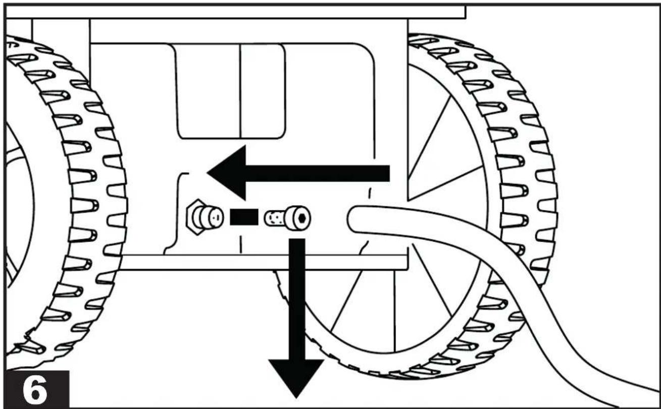
▶▶4.3. DISCHARGE PIPE CONNECTION (Set-up)
(FIG. 6)
A discharge pipe can be connected to the appliance. A hose connection with a diameter of 16 mm is fitted on the tank.
▶▶4.4. CONNECTION OF THE CON-DENSATE PUMP (Optional)
Depending on the model, the appliance can be set up for the connection of the condensate discharge pump.
For a correct connection, disconnect the unit from the power supply before carrying out any operation.
For a correct installation of the condensate pump, refer to the technical manual included in the optional kit.
▶▶▶5. MAINTENANCE
▶▶5.1. CHECKS TO BE PERFORMED BY THE USER
(FIG. 7)
The only maintenance to be carried out by the user is the cleaning of the air filter, which must be performed at least once a month.
The cleaning frequency can be increased due to the dustiness of the working environment of the appliance.
CAUTION: REMOVE THE FILTER FROM THE APPLIANCE TO PERFORM CLEANING. IT IS FORBIDDEN TO PERFORM CLEANING WITH THE FILTER INSTALLED.
▶▶5.2. SPARE PARTS
Should it be required to replace one or more parts during maintenance by specialised operators, this must be done by using original spare parts only.
If required, request the “spare parts list” from your vendor, specifying the model and serial number of the unit.
▶▶5.3. DISMANTLING THE UNIT
The unit has been designed and built to ensure continuous operation. The lifespan of some components such as the fan and the compressor depends on their maintenance.
CAUTION: The unit contains substances and components dangerous for the environment (electronic components, refrigerant gas and oils). At the end of its useful life, in the event of dismantling the unit, the operation must be carried out by specialised refrigerating personnel.
The unit must be sent to specific specialised centres for the collection and disposal of equipment containing dangerous substances. The refrigerant fluid and the lubricating oil contained in the circuit must be recovered, in accordance with the regulations in force in your country.
▶▶▶6. ALARM LIST
| ALARM POSSIBLE CAUSE | POSE POSSIBLE SOLUTION | |
| FULL + “FULL” Tank full or missing The alarm is reset automatically by emptying or inserting the tank | ||
| ALARM + “Lo t” Room temperature too low | Room temperature conditions not suitable for operation | |
| ALARM + “Prob” Humidity probe malfunction. In any case, the unit continues to function | Contact the authorised assistance centre | |
| ALARM + “Pro3” Room temperature probe malfunction.The dehumidifier goes into stand-by mode | Contact the authorised assistance centre | |
| ALARM + “dEFr” Defrost thermostat malfunction.The dehumidifier goes into stand-by mode | Contact the authorised assistance centre | |
▶▶▶3. OPÉRATIONS PRÉLIMINAIRES
▶▶3.1. DÉBALLAGE ET ASSEMBLAGE
▶▶4.3. BRANCHEMENT D'UN TUYAU D'ÉVACUATION (agencement)
(FIG. 6)
▶▶1.3. INDIVIDUELE BESCHERMINGS-MIDDELEN
▶▶▶3. WERKZAAMHEDEN VOORAF
▶▶3.1. VERWIJDERING VAN DE VERPAKKING EN MONTAGE
▶▶3.3. WERKINGSLIMIETEN
▶▶▶4. INWERKINGSTELLEN
▶▶4.1. CONTROLES VOORAF
▶▶4.3. AANSLUITING AFVOERBUIS (Inrichting)
(FIG. 6)
▶▶4.3. POISTOPUTKEN KYTKEMI- NEN (Valmius)
(KUVA 6)
▶▶1.3. OSOBNÍ OCHRANNÉ PRO-STŘEDKY
▶▶5.3. DEMONTÁŽ JEDNOTKY
▶▶5.1. KONTROLE, ZA KATERE JE ZADOLŽEN UPORABNIK
(SL. 7)
▶▶▶2. VISPÄRİGS IEKÄRTAS AP- RAKSTS
(ATT. 1)
▶▶2.1. SALDĚŠANAS SISTĚMA
▶▶▶5. TEHNISKÄ APKOPE
▶▶5.1. PÄRBAUDES, KURAS JÄVEIC LIETOTÄJAM
(ATT. 7)
▶5.3. SEADME LAMMUTAMINE
▶▶1.3. OSOBNÉ OCHRANNÉ PRO-STRIEDKY
▶▶5.3. DEMONTÁŽ JEDNOTKY
▶5.3. ΔΙΑΘΕΣΗ ΤΗΣ ΜΟΝΑΔΑΣ
▶▶▶6. ΛΙΣΤΑ ΣΥΝΑΓΕΡΜΩΝ
▶ en - DISPOSAL OF THE PRODUCT
-This product has been designed and manufactured with top-quality materials and components, which can be re-cycled and re-used. -When a crossed-wheely bin symbol is attached to the product, it means that the product is protected by the, 2012/19/UE European Directive.
-Please obtain information regarding the local differentiated collection system for electrical and electronic products.
-Respect local Standards in force and do not dispose of old products as normal domestic waste. Correct disposal of the product helps to prevent possible negative consequences for health, the environment and mankind.
▶ Iv - PRODUKTA IZNĪCINĀŠANA
natural_image
Abstract geometric composition with yellow and black blocks (no text or symbols)Dantherm S.p.A.
Via Gardesana 11
37010 Pastrengo (VR)
Italy
t.: +39 045 6770533
e.: info.it@danthermgroup.com

DOWNLOAD CATALOGUE

SEND US YOUR FEEDBACK

REGISTER FOR
3-YEAR WARRANTEE

- USER AND MAINTENANCE MANUAL
- ▶▶▶1. INTRODUCTION
- ▶▶1.1. INTRODUCTION
- ▶▶1.2. GENERAL SAFETY RULES
- ▶▶1.3. PERSONAL PROTECTIVE EQUIPMENT
- ▶▶1.4. GENERAL SAFETY RULES
- ▶▶▶2. GENERAL DESCRIPTION OF THE UNIT
- ▶▶2.1. REFRIGERANT CIRCUIT
- Flammable material hazard.
- ▶▶▶3. PRELIMINARY OPERATIONS
- ▶▶3.1. REMOVAL OF THE PACKAGING AND ASSEMBLY
- ▶▶3.2. INSPECTION
- ▶▶3.3. OPERATING PRINCIPLES
- ▶▶3.4. POSITIONING
- ▶▶3.5. SERVICE AREA
- ▶▶3.6. GENERAL INFORMATION
- ▶▶▶4. START-UP
- ▶▶4.1. PRELIMINARY CHECKS
- ▶▶4.2. CONTROL PANEL
- CONTROL PANEL:
- LED:
- BUTTONS:
- ▶▶4.3. DISCHARGE PIPE CONNECTION (Set-up)
- ▶▶4.4. CONNECTION OF THE CON-DENSATE PUMP (Optional)
- ▶▶▶5. MAINTENANCE
- ▶▶5.1. CHECKS TO BE PERFORMED BY THE USER
- ▶▶5.2. SPARE PARTS
- ▶▶5.3. DISMANTLING THE UNIT
- ▶▶▶3. OPÉRATIONS PRÉLIMINAIRES
- ▶▶3.1. DÉBALLAGE ET ASSEMBLAGE
- ▶▶4.3. BRANCHEMENT D'UN TUYAU D'ÉVACUATION (agencement)
- ▶▶1.3. INDIVIDUELE BESCHERMINGS-MIDDELEN
- ▶▶▶3. WERKZAAMHEDEN VOORAF
- ▶▶3.1. VERWIJDERING VAN DE VERPAKKING EN MONTAGE
- ▶▶3.3. WERKINGSLIMIETEN
- ▶▶▶4. INWERKINGSTELLEN
- ▶▶4.1. CONTROLES VOORAF
- ▶▶4.3. AANSLUITING AFVOERBUIS (Inrichting)
- ▶▶4.3. POISTOPUTKEN KYTKEMI- NEN (Valmius)
- ▶▶1.3. OSOBNÍ OCHRANNÉ PRO-STŘEDKY
- ▶▶5.3. DEMONTÁŽ JEDNOTKY
- ▶▶5.1. KONTROLE, ZA KATERE JE ZADOLŽEN UPORABNIK
- ▶▶▶2. VISPÄRİGS IEKÄRTAS AP- RAKSTS
- ▶▶2.1. SALDĚŠANAS SISTĚMA
- ▶▶▶5. TEHNISKÄ APKOPE
- ▶▶5.1. PÄRBAUDES, KURAS JÄVEIC LIETOTÄJAM
- ▶5.3. SEADME LAMMUTAMINE
- ▶▶1.3. OSOBNÉ OCHRANNÉ PRO-STRIEDKY
- ▶5.3. ΔΙΑΘΕΣΗ ΤΗΣ ΜΟΝΑΔΑΣ
- ▶ en - DISPOSAL OF THE PRODUCT
- ▶ Iv - PRODUKTA IZNĪCINĀŠANA
Brand : Master
Model : DH 62
Category : Humidifier