
SOL SH0805 P2 - Lighting BRENNENSTUHL - Free user manual and instructions
Find the device manual for free SOL SH0805 P2 BRENNENSTUHL in PDF.
| Product type | Outdoor solar light with motion detector |
| Brand | Brennenstuhl |
| Model | SOL SH0805 P2 |
| Solar panel dimensions | 220 x 190 mm |
| Number of LEDs | 8 x 0.5 W |
| Battery type | 3 x 1.2 V / 2200 mAh Ni-MH (rechargeable) |
| Adjustable lighting duration | Approximately 10 seconds to 1 minute |
| Detection angle | 180° horizontal |
| Detection range | Up to 10 meters |
| Response sensitivity | Adjustable from daylight to night |
| Protection rating | IP44 |
| Ambient temperature | -15°C to +45°C |
| Power supply | Photovoltaic solar panel |
| Mounting | Wall-mounted, screwed onto stable support |
| Main functions | Motion detection, duration and sensitivity adjustment, ON/OFF switch |
| Maintenance and cleaning | Clean the solar panel and detector with a damp cloth; do not use chemical products |
| Safety | Use only the provided solar panel; disconnect before replacing the battery; respect polarity |
| Spare parts and repairability | Replaceable battery (Ni-MH AA 1.2 V); solar panel not interchangeable |
| General information | Warranty: refer to manufacturer; disposal according to WEEE directive |
Frequently Asked Questions - SOL SH0805 P2 BRENNENSTUHL
User questions about SOL SH0805 P2 BRENNENSTUHL
0 question about this device. Answer the ones you know or ask your own.
Ask a new question about this device
Download the instructions for your Lighting in PDF format for free! Find your manual SOL SH0805 P2 - BRENNENSTUHL and take your electronic device back in hand. On this page are published all the documents necessary for the use of your device. SOL SH0805 P2 by BRENNENSTUHL.
USER MANUAL SOL SH0805 P2 BRENNENSTUHL
natural_image
Line drawing of a robotic arm holding a rectangular device with a grid and probe, no text or symbols presentDE INSTALLATIONS- UND BEDIENUNGSANLEITUNG .... 2
GB INSTRUCTIONS FOR INSTALLATION AND USE 6
MODE D'INSTALLATION ET D'EMPLOI 9
NL INSTALLATIE- EN BEDIENINGSHANDLEIDING .... 13
⑪ ISTRUZIONI PER L'INSTALLAZIONE E L'USO...... 16
SE INSTALLATIONS- UND BRUKSANVISNING.... 20
ES MANUAL DE INSTALACIÓN Y OPERACIÓN 23
PL INSTRUKCJA INSTALACJI I OBSŁUGI 26
CZ NÁVOD K INSTALACI A POUŽÍVÁNÍ PŘÍSTROJE ...... 30
HU TELEPÍTÉSI ÉS KEZELÉSI UTASÍTÁS 33
TR KURULUM VE KULLANMA KILAVUZU 36
ASENNUS- JA KÄYTTÖOHJE 39
GR OΔΗΓΙΕΣ ΕΓΚΑΤΑΣΤΑΣΗΣ ΚΑΙ ΧΡΗΣΗΣ 42
RU РУКОВОДСТВО ПО УСТАНОВКЕ И ОБСЛУЖИВАНИЮ ИЗДЕЛИЯ 46
PT INSTRUÇÕES DE INSTALAÇÃO E MANUAL DO UTILIZADOR .... 50
EE PAIGALDUS- JA KASUTUSJUHEND 54
SK NÁVOD NA INŠTALÁCIU A POUŽÍVANIE PRÍSTROJA.... 57
SI NAVODILA ZA INŠTALACIJO IN UPORABO....60
LV INSTALĀCIJAS UN LIETOŠANAS INSTRUKCIJA....63
LT IRENGIMO IR NAUDOJIMO INSTRUKCIJA 66
ERSTMALIGES AUFLADEN DER SOLARLEUCHTE
natural_image
Technical line drawing of a mechanical tool with a magnified inset showing a detail (no text or symbols)Bild 1 Bild 2

natural_image
Diagram of a handheld device with a hand holding a pointer, showing mechanical components and motion direction (no text or symbols)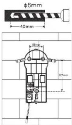
Bild 3 Bild 4

natural_image
Technical line drawing of a mechanical device with internal components and an external assembly (no text or symbols)Bild 5

Bild 6 Bild 7
natural_image
Diagram of a showerhead with water flow indicators (no text or symbols)
natural_image
Technical diagram showing a wall-mounted device with a fan and directional arrows indicating rotation or assembly (no text or symbols present)Bild 11 Bild 12
Solarmodul:

natural_image
Technical line drawing of a mechanical component with a rotating shaft and housing (no text or symbols)Bild 8
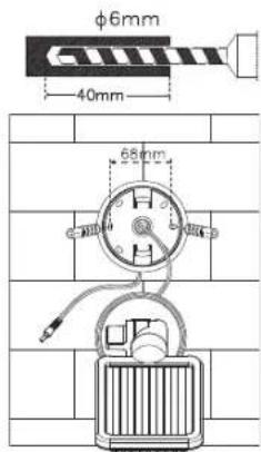
Bild 9 Bild 10
natural_image
Diagram of a wall-mounted handheld device with attached cable, mounted on a brick wall (no text or symbols)GB INSTRUCTIONS FOR INSTALLATION AND USE
SOL SH0805 P1 IP44, SOL LH0805 P1 IP44, SOL SH0805 P2 IP44, SOL LH0805 P2 IP44, SOL SH1205 P2 IP44, SOL LH1205 P2 IP44
We'd like to thank you for purchasing this product.
Please familiarise yourself with the product before using it for the first time. Read the following instructions and safety notes carefully. Use the device as described and for the specified purposes only.
Do not throw away these instructions. Include all documentation if giving the device to a third party.
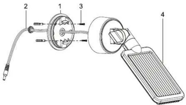
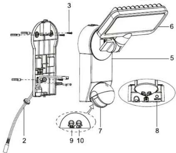
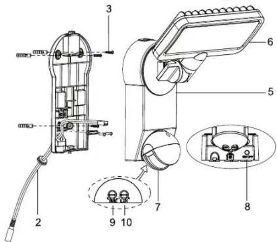
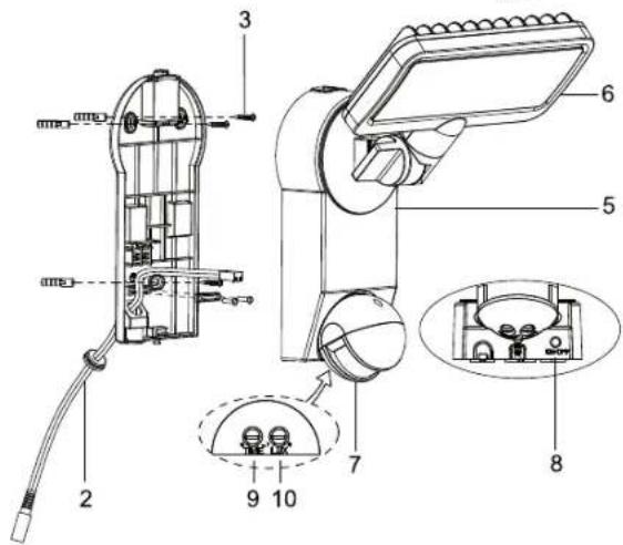
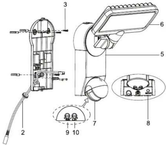
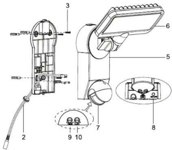
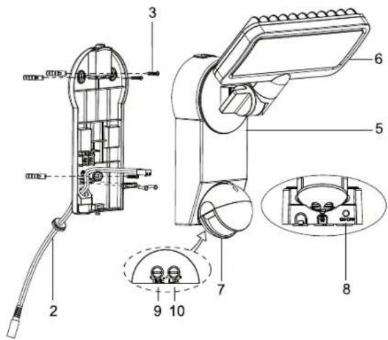
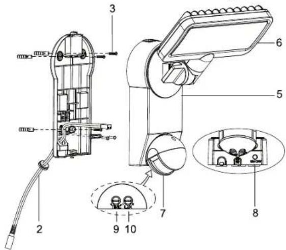
PARTS LIST
1 Solar panel mounting bracket
2 Solar panel connection cable
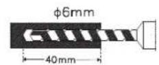
3 Solar module mounting screws and main unit mounting screws (5x)
4 Solar module
5 Main unit
6 LED unit
7 Motion detector
8 ON / OFF switch
9 Light ON time adjustment knob
10 Sensitivity adjustment knob
CHARGING THE SOLAR LIGHT FOR THE FIRST TIME
Before you can use your solar light it must be charged using the solar module.
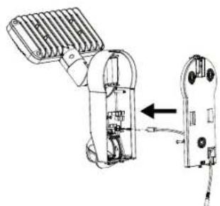
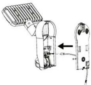
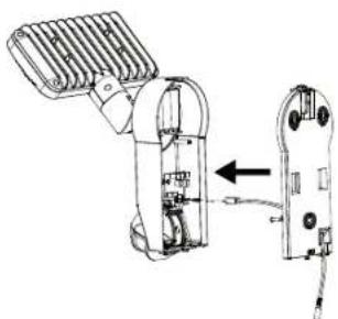
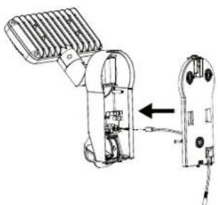
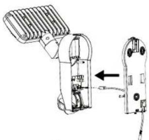
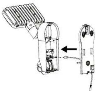
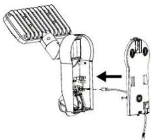
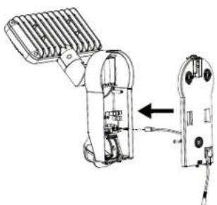
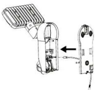
Connect the solar module cable with the main unit.
The ON / OFF switch on the main unit must be set to OFF.
Put the solar module in a location where it will get maximum exposure to direct sunlight. Refer to the notes on suitable installation locations in the following section.
Depending on the season, the weather and the location of the solar module charging may take up to 4 days before the light is ready for use.
SUITABLE LOCATIONS FOR INSTALLING THE SOLAR LIGHT AND THE SOLAR MODULE
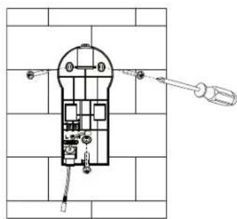
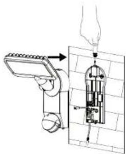
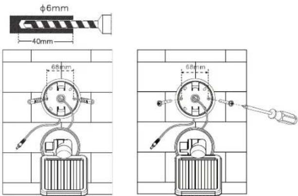
Main Unit:
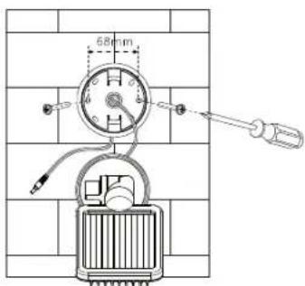
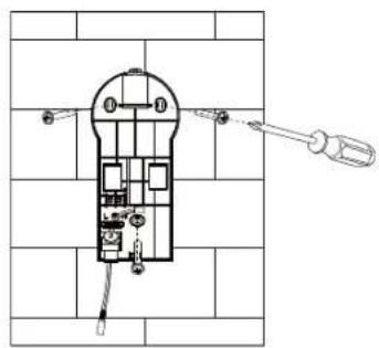
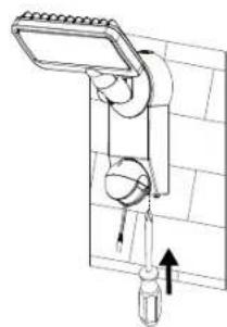
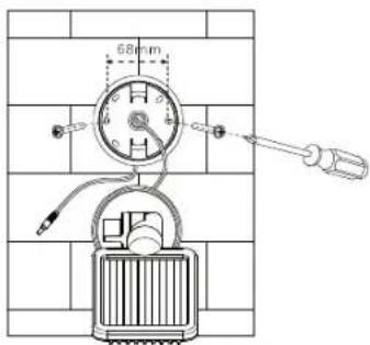
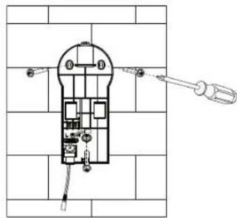
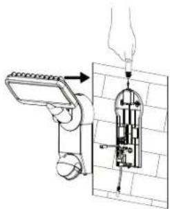
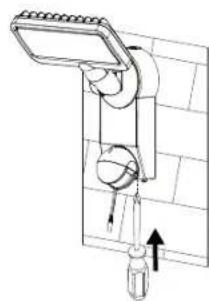
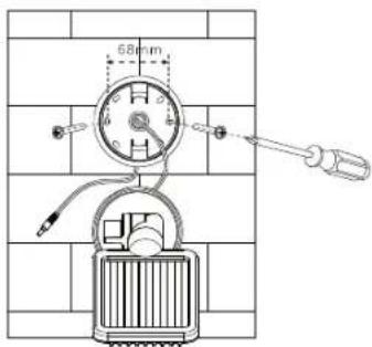
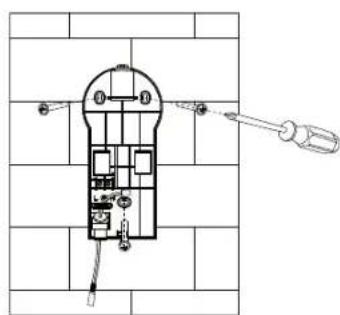
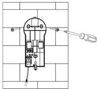
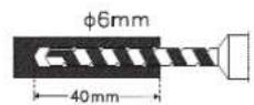
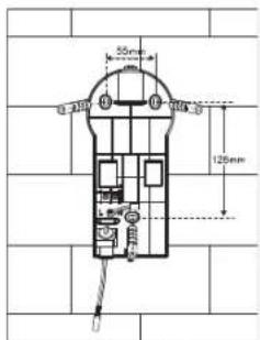
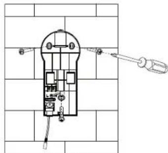
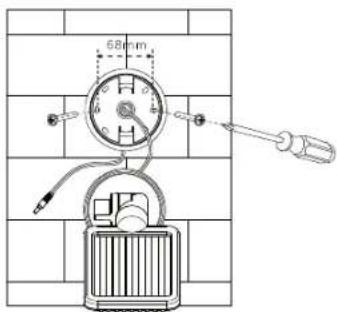
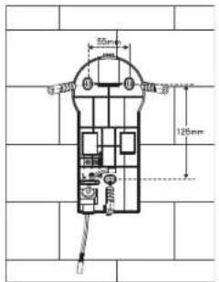
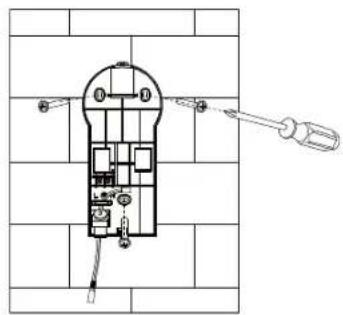
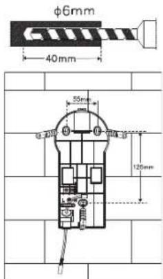
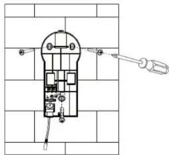
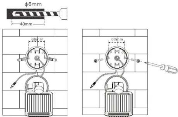
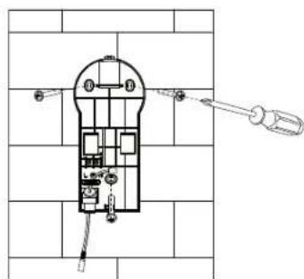
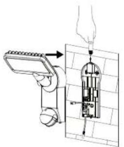
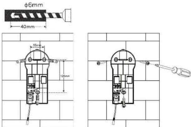
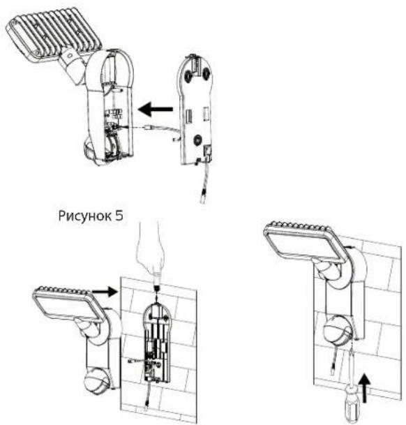
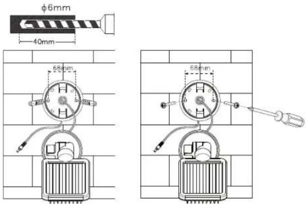
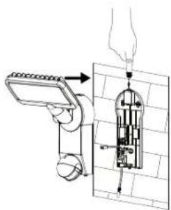
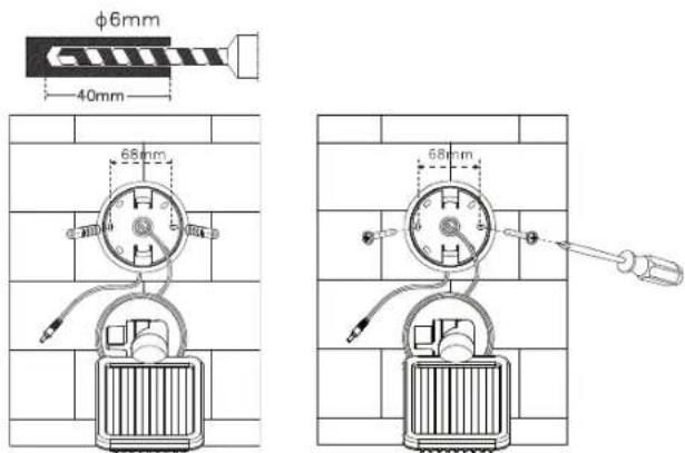
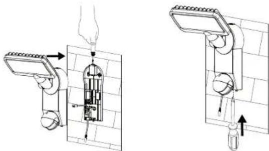
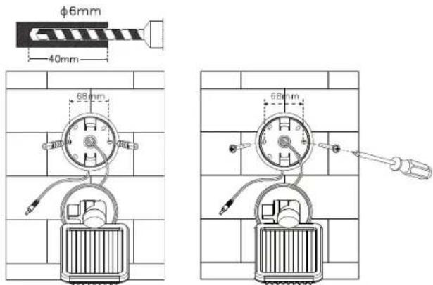
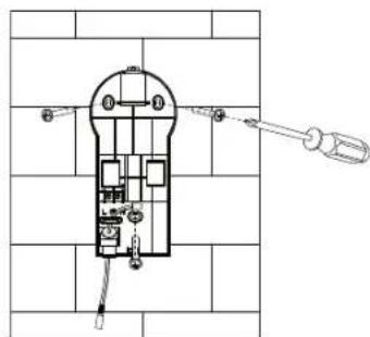
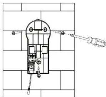
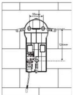
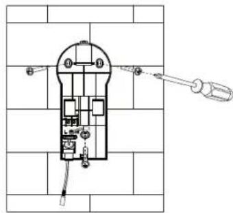
The main unit contains the light, the motion detector and the batteries. Please note when installing the main unit that the monitoring range of the motion detector is a maximum of 180^ within an 10-metre range, depending on installation height. Use the screws included in the package (item 3 on the parts list) for installing the light on a firm surface, such as a wall. Use screws and screw anchors that are suitable for the installation surface.
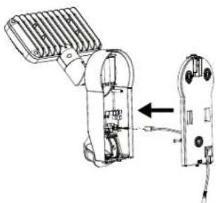
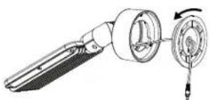
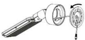
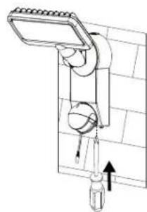
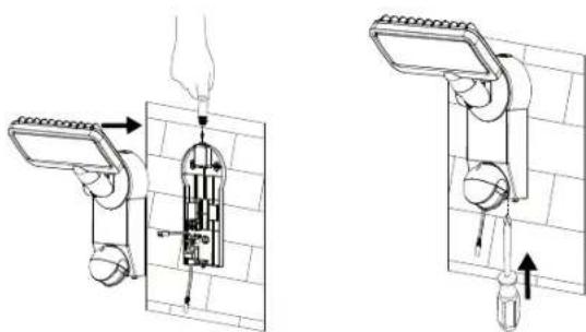
Installation:
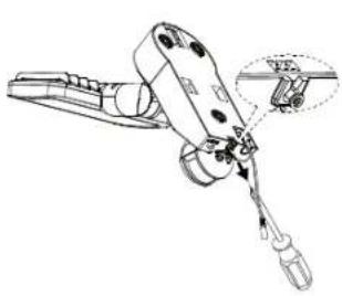
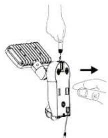
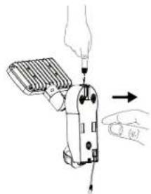
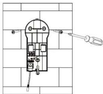
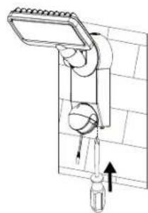
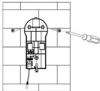
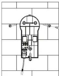
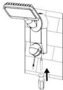
- Loosen the screw (Fig. 1) of the wall bracket
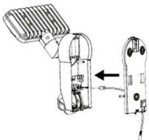
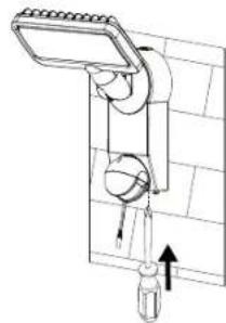
- Press the release button on the top side (Fig. 2) and open the cover by pulling the wall bracket
- Avoid damaging existing cables or wires when drilling mounting holes in the wall or when tightening the screws
natural_image
Technical line drawing of a mechanical clamp or tool with a magnified inset showing a detail (no text or symbols)Fig. 1 Fig. 2
natural_image
Illustration of a handheld device with hands operating it, showing a lever and cable (no text or symbols)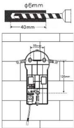
Fig. 3 Fig. 4
natural_image
Technical line drawing of a mechanical device with internal components and an arrow indicating assembly (no text or symbols)Fig. 5
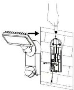
Fig. 6 Fig. 7
natural_image
Diagram of a mechanical device with directional arrows indicating movement or force (no text or symbols present)
natural_image
Technical diagram showing a wall-mounted air vent and its mechanical assembly with directional arrows (no text or symbols)Fig. 11 Fig. 12
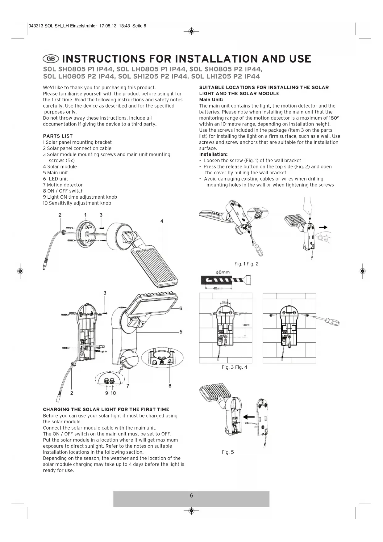
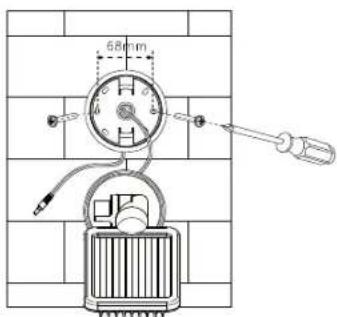
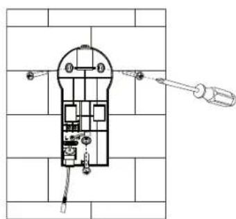
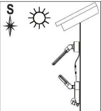
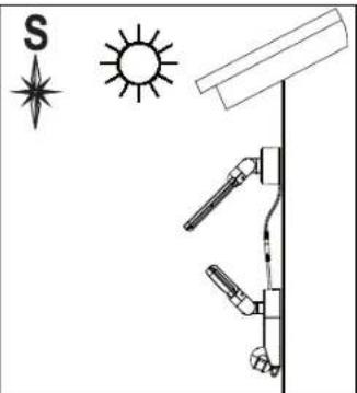
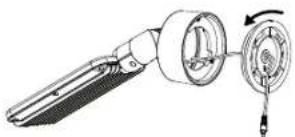
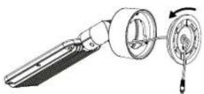
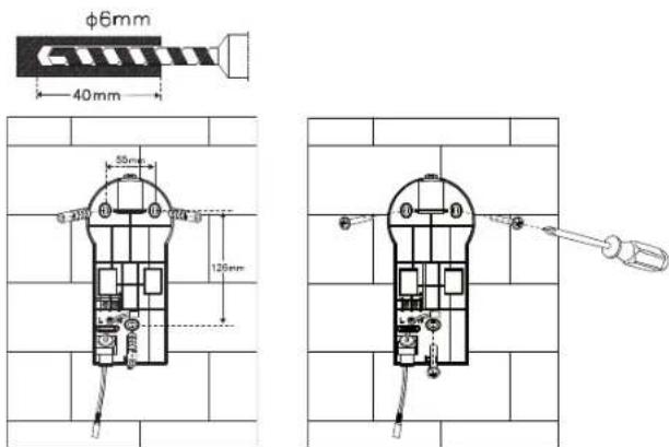
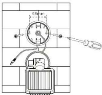
Solar Module:
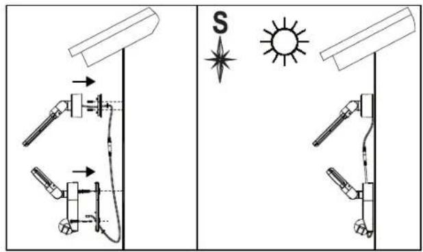
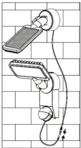
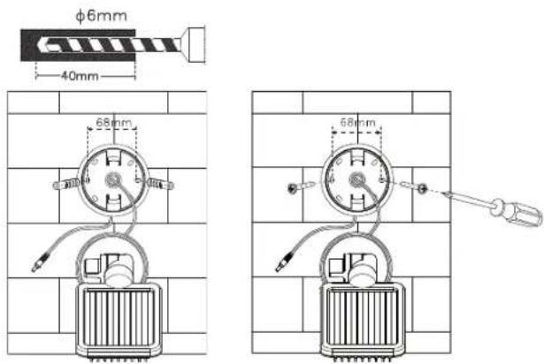
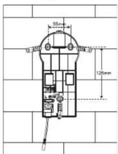
The solar module is the main power source of the solar light. It converts sunlight into electricity and charges the batteries. Please keep in mind when installing the solar module that the photovoltaic cell works best in DIRECT SUNLIGHT. The longer the photovoltaic cell is exposed to direct sunlight, the longer the light can be used. Ideally, the solar module should face south in order to capture direct solar radiation. Avoid shade of any kind. For Central Europe, we recommend an angle of approx. 30^ - 40^ . Use the screws included in the package (item 3 of the parts list) to install the solar module on a firm surface, such as a wall. Use screws and screw anchors that are suitable for the installation surface.

natural_image
Technical line drawing of a mechanical component with a rotating shaft and housing (no text or symbols)Fig. 8

Fig. 9 Fig. 10
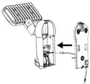
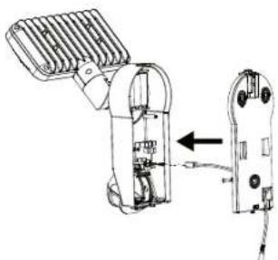
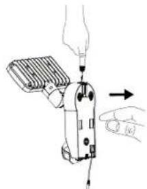
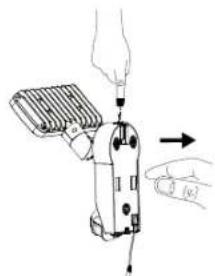
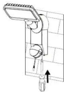
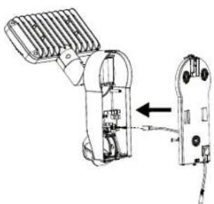
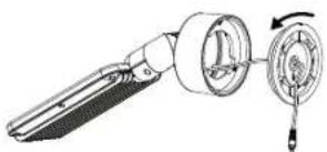
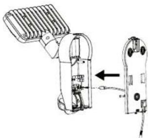
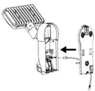
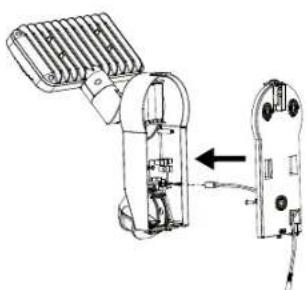
Position the cable between the photovoltaic cell and the main unit and connect the cable of the main unit with that of the photovoltaic cell by connecting the plug and the socket.
natural_image
Technical line drawing of a wall-mounted device with attached cable and sensor components (no text or symbols)ADJUSTMENT AND INITIAL OPERATION
After successful installation of the solar light the device can be adjusted in a few simple steps.
Important:
Make sure the solar light has been charged as described under "Charging the Solar Light for the First Time" before the light is switched on.
The main unit features a switch with two settings:
ON: Setting used with the motion detector.
OFF: Switches off the motion detector feature / LED light.
Setting used for charging.
Adjusting the Motion Detector
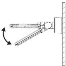
Switch the button to the ON position after initial charging has been completed. Point the motion detector in the direction you wish to monitor. Set the ⏻ adjustment knob on the back side of the motion detector to "Minimum" (-) and the LUX adjustment knob to "Light" (○). Test the detection range by slowly circling the area to be monitored. If the solar light does not light up as desired the angle of the motion detector must be adjusted.
The motion detector has two adjustment knobs:
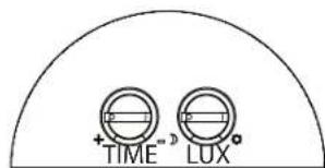
(TIME) = light ON time: The length of time the light remains on after a movement has been detected can be adjusted to anywhere between approx. 10 seconds and 1 minute. Turn the
TIME knob towards the (+) sign to increase the light ON time or towards the (-) sign to decrease the light ON time.
Please note: The selected cycle will start after the motion detector has been triggered. The cycle starts over with each subsequent detection.
©/©(LUX) = Sensitivity: The LUX adjustment knob can be used to adjust the amount of ambient light required for the device to switch on. This helps to prevent the light from switching on during daylight hours. In the (©) position the light switches on during the day and at night, whereas in the (©) position it only comes on at night. The desired ambient light at which the unit starts operating can be adjusted with the LUX adjustment knob.
REPLACING THE BATTERY
Please note: Before replacing the battery the switch on the lamp unit must be set to OFF and the solar module must be disconnected from the main unit. To replace the battery, open the cover of the main unit as described in Fig. 1 and 2 in the section "Main Unit". Remove the old batteries from the holder and insert new ones If possible, charge the rechargeable batteries first using a standard charger for 1.2 V AA NiMH batteries. If unable to charge the batteries with a charger please follow the instructions in the section "CHARGING THE SOLAR LIGHT FOR THE FIRST TIME". Reverse the instructions to re-assemble the device.
Please note: Pay attention to correct polarity when inserting the batteries. Incorrect polarity may damage the device and the batteries.
GENERAL SAFETY NOTES
- Only use the solar module included in the delivery. Using a different solar module may result in injuries or damage to the light and may void the warranty.
- When installing the cable make sure it is fastened securely and does not pose a hazard (e.g., tripping hazard). Stop using the solar light if the cable is damaged or defective.
CLEANING
Keep the motion detector free from dust and deposits by wiping it with a damp cloth from time to time. Do not use chemicals or abrasives to clean the device. Keep the solar module free from dirt and deposits. A dirty photovoltaic cell is unable to fully charge the batteries. This may reduce the life of the battery and result in an unreliable device.
STORAGE
To avoid damaging the batteries, follow these steps to store your light inside the house for longer than two or three days:
- Turn the switch to the OFF position.
- Store the light and the solar module in a location where they will be exposed to sunlight or ambient light every day. The rechargeable batteries require light in order to stay charged during storage.
- If storing the unit for an extended period it must be fully charged every four months. Avoid long storage times to maintain performance.
MALFUNCTIONS
(FAILURE / CAUSE→REMEDY)
The light doesn't turn on when there is movement within the monitoring range.
Possible Solutions:
Make sure that:
- The switch is in the ON position.
- The LUX adjustment knob is not turned too far towards (C)
- The motion detector is set at the correct angle for detecting movement.
- The photovoltaic cell is aligned to receive as much direct sunlight as possible during the day.
- The battery charge is not too low (charge over 3-4 sunny days with the switch set to OFF).
The light turns on during the day.
Possible Solutions:
- Make sure the LUX adjustment knob is not turned too far towards (2).
More information can be found in the Service/FAQ section on our homepage, www.brennenstuhl.com.
SPECIFICATIONS:
Batteries:
SOL SH0805 P1 IP44, SOL LH0805 P1 IP44,
SOL SH0805 P2 IP44, SOL LH0805 P2 IP44:
3 x 1.2 V / 2200 mAh Ni-MHrechargeable batteries
SOL SH1205 P2 IP44, SOL LH1205 P2 IP44:
3 x 1.2 V / 2500 mAh Ni-MHrechargeable batteries
Solar Module:
SOL SH0805 P1 IP44, SOL LH0805 P1 IP44:
190 x 115 mm
SOL SH0805 P2 IP44, SOL LH0805 P2 IP44,
SOL SH1205 P2 IP44, SOL LH1205 P2 IP44:
220 x 190 mm
Number of LEDs:
SOL SH0805 P1 IP44, SOL LH0805 P1 IP44,
SOL SH0805 P2 IP44, SOL LH0805 P2 IP44:
8 x 0,5 W
SOL SH1205 P2 IP44, SOL LH1205 P2 IP44:
12 x 0,5 W
adjustable: from approx. 10 seconds to 1 minute
Sensing angle: 180° horizontal
Range: max. 10 metres
Sensitivity: adjustable from daylight to night
Type of protection: IP44
Ambient temperature: -15 °C - +45 °C
DISPOSAL
Dispose of electrical devices in an environmentally responsible manner! Do not dispose of electrical devices with household rubbish.
In accordance with Directive 2012/19/EU on waste electrical and electronic equipment, used electrical equipment must be collected separately and reused or recycled in an environmentally responsible manner. Please contact your local authorities for available disposal options for your worn-out device.
Improper disposal of batteries and rechargeable batteries damages the environment!
Batteries and rechargeable batteries do not belong in the household rubbish. They may contain toxic heavy metals and must be treated as hazardous waste. Please take your used batteries to a community collection centre.
FR MODE D'INSTALLATION ET D'EMPLOI
SOL SH0805 P1 IP44, SOL LH0805 P1 IP44, SOL SH0805 P2 IP44, SOL LH0805 P2 IP44, SOL SH1205 P2 IP44, SOL LH1205 P2 IP44
PREMIER CHARGEMENT DE LA LAMPE SOLAIRE
natural_image
Technical line drawing of a mechanical tool with a magnified inset showing a component detail (no text or symbols)Image 1 Image 2
natural_image
Illustration of a handheld device with a hand adjusting its tip, showing no text or symbols.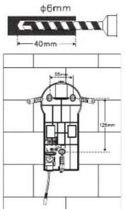
Image 3 Image 4
natural_image
Technical illustration of a mechanical device with internal components and a separate view showing a close-up of its internal structure (no text or symbols present)Image 5

Image 6 Image 7

natural_image
Diagram of a mechanical device with directional arrows indicating motion or force (no text or symbols)
natural_image
Technical diagram showing a wall-mounted air vent and its mechanical assembly with directional arrows (no text or symbols)Image 11 Image 12
Module solaire :
natural_image
Technical line drawing of a mechanical component with a rotating dial and shaft (no text or symbols)Image 8
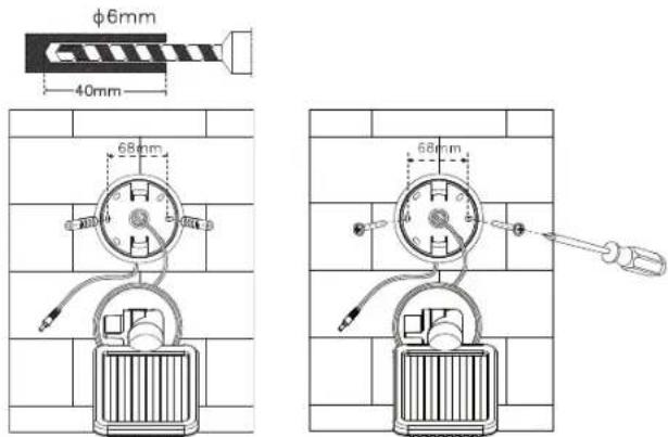
Image 9 Image 10
natural_image
Technical line drawing of a wall-mounted device with attached cable and sensor components (no text or symbols)(TROUBLE / CAUSE →REMÈDE)

EERSTE KEER OPLADEN VAN DE ZONNELAMP
natural_image
Technical line drawing of a mechanical device with a close-up inset showing a component labeled 'PE' (no text or symbols present)Afb.1 Afb.2

natural_image
Illustration of a hand using a handheld device to interact with a tool, showing no text or symbols.
Afb. 3 Afb. 4
natural_image
Technical line drawing of a mechanical device with internal components and an external housing (no text or symbols)Afb. 5
Afb. 6 Afb. 7

natural_image
Diagram of a mechanical device with directional arrows indicating motion or force (no text or symbols)Zonnemodule:

natural_image
Technical line drawing of a mechanical component with a rotating shaft and housing (no text or symbols)Afb. 8

Afb. 9 Afb. 10

natural_image
Technical diagram showing a wall-mounted heating element and its mechanical assembly with directional arrows (no text or symbols)Afb. 11 Afb. 12
natural_image
Technical line drawing of a wall-mounted electrical meter with attached cable, mounted on a grid-patterned wall (no text or symbols)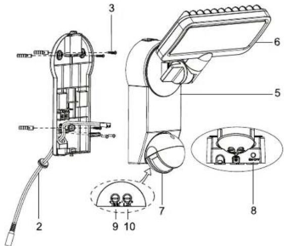
PRIMA CARICA DELLA LAMPADA SOLARE
natural_image
Technical line drawing of a mechanical clamp or tool with a magnified inset showing a detail (no text or symbols)Illustr. 1 Illustr. 2

natural_image
Illustration of a handheld device with a hand holding a screwdriver, showing motion direction (no text or symbols)
Illustr. 3 Illustr. 4
natural_image
Technical line drawing of a mechanical device with internal components and an external housing (no text or symbols)Illustr. 5
Illustr. 6 Illustr. 7
natural_image
Technical line drawing of a mechanical device with directional arrows indicating motion (no text or symbols)
natural_image
Technical diagram showing a wall-mounted air vent and its mechanical assembly with directional arrows (no text or symbols)Illustr. 11 Illustr. 12
Modulo solare:

natural_image
Technical line drawing of a mechanical component with a rotating shaft and housing (no text or symbols)Illustr. 8

Illustr. 9 Illustr. 10
natural_image
Diagram of a wall-mounted handheld device with attached cable, mounted on a brick wall (no text or symbols)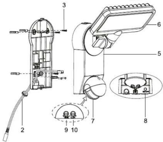
FÖRSTA UPPLADDNINGEN AV SOLCELLSLAMPAN
natural_image
Technical line drawing of a mechanical clamp or tool with a magnified inset showing a detail (no text or symbols)Bild 1 Bild 2

natural_image
Illustration of a handheld device with a hand holding a screwdriver, showing motion direction (no text or symbols)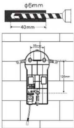
Bild 3 Bild 4
natural_image
Technical illustration of a mechanical device with internal components and a separate view showing a cable or connector (no text or symbols present)Bild 5
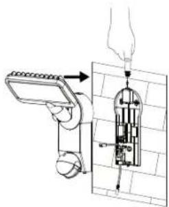
Bild 6 Bild 7

natural_image
Diagram of a mechanical device with directional arrows indicating motion or force (no text or symbols)Solcellsmodulen:
natural_image
Diagram showing a sun, compass, and vertical pole with mechanical components (no text or labels)
natural_image
Technical line drawing of a mechanical component with a rotating shaft and housing (no text or symbols)Bild 8
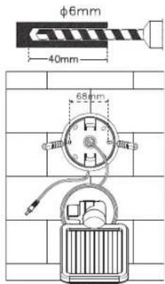
Bild 9 Bild 10

natural_image
Technical diagram showing a wall-mounted air vent and its mechanical assembly with directional arrows (no text or symbols)Bild 11 Bild 12
natural_image
Technical line drawing of a wall-mounted device with attached cables, no text or symbols presentINSTÄLLNING OCH IDRIFTSTAGANDE
PRIMERA CARGA DE LA LÁMPARA SOLAR
natural_image
Technical line drawing of a mechanical clamp or tool with a magnified inset showing a detail (no text or symbols)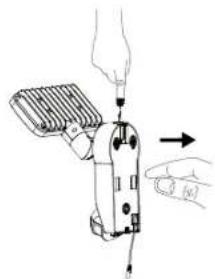
natural_image
Illustration of a handheld device being adjusted with a tool, showing hand positioning and control buttons (no text or symbols)Figura 1 Figura 2
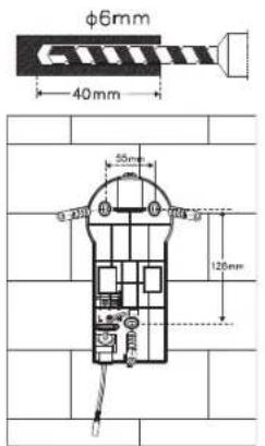
Figura 3 Figura 4
natural_image
Technical line drawing of a mechanical device with internal components and an external connector (no text or symbols)Figura 5

Figura 6 Figura 7

natural_image
Diagram of a mechanical device with directional arrows indicating motion or force (no text or symbols)
natural_image
Technical diagram showing a wall-mounted air vent and its mechanical assembly with directional arrows (no text or symbols)Figura 11 Figura 12
Módulo solar:
natural_image
Technical line drawing of a mechanical component with a rotating shaft and housing (no text or symbols)Figura 8
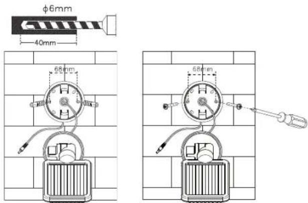
Figura 9 Figura 10
natural_image
Technical line drawing of a wall-mounted electrical meter with attached cable, no text or symbols present
PIERWSZE LADOWANIE LAMPY SOLARNEJ
natural_image
Technical line drawing of a mechanical clamp or tool with a magnified inset showing a small component (no text or symbols)Ilustr.1 Ilustr.2
natural_image
Illustration of a hand using a handheld device to interact with a tool, showing no text or symbols present.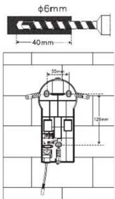
Ilustr. 3 Ilustr. 4

natural_image
Technical line drawing of a mechanical device with internal components and an external connector (no text or symbols)llustr. 5

Ilustr. 6 Ilustr. 7

natural_image
Diagram of a showerhead with water flow indicators (no text or symbols)
natural_image
Technical diagram showing a wall-mounted air vent and its mechanical assembly with directional arrows (no text or symbols)Ilustr. 11 Ilustr. 12
Moduł solarny:

natural_image
Technical line drawing of a mechanical component with a rotating shaft and housing (no text or symbols)Ilustr. 8

Ilustr. 9 Ilustr. 10
natural_image
Diagram of a wall-mounted handheld device with attached cable, mounted on a brick wall (no text or symbols)USTAWIENIE I URUCHOMIENIE

PRVNÍ NABITÍ SOLÁRNÍ LAMPY
natural_image
Technical line drawing of a mechanical clamp or tool with a magnified inset showing a small component (no text or symbols)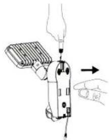
natural_image
Illustration of a hand using a handheld device to interact with a tool, showing no text or symbols present.Obrázek 1 Obrázek 2
Obrázek 3
Obrázek 4
natural_image
Technical line drawing of a mechanical device with internal components and an external connector (no text or symbols)Obrázek 5

Obrázek 6
natural_image
Diagram of a mechanical device with directional arrows indicating motion or force (no text or symbols)Obrázek 7
Solární modul:
natural_image
Diagram showing a sun, compass, and vertical pole with mechanical components (no text or labels)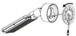
natural_image
Technical line drawing of a mechanical component with a rotating dial and housing (no text or symbols)Obrázek 8

Obrázek 9
Obrázek 10

natural_image
Diagram of a wall-mounted air vent with cooling fan and pipe connection (no text or symbols)Obrázek 11
natural_image
Diagram of a mechanical lever mechanism with rotational motion indicator (no text or symbols)Obrázek 12
natural_image
Diagram of two wall-mounted sensors mounted on a grid-patterned surface, no text or symbols presentNASTAVENÍ A UVEDENÍ DO PROVOZU

A NAPELEMES LÁMPA ELSŐ FELTÖLTÉSE
natural_image
Technical line drawing of a mechanical clamp or tool with a magnified inset showing a detail (no text or symbols)kép 1 kép 2
natural_image
Illustration of a handheld device with a hand holding a tool, showing motion direction (no text or symbols)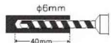
kép 3 kép 4
natural_image
Technical illustration of a mechanical device with internal components and a separate view showing a close-up of a component (no text or symbols present)kép 5

kép 6 kép 7
natural_image
Diagram of a mechanical device with directional arrows indicating motion or force (no text or symbols)Napelemes modul:

natural_image
Technical line drawing of a mechanical component with a rotating shaft and housing (no text or symbols)kép 8

kép 9 kép 10


natural_image
Technical diagram showing a wall-mounted heating element and its mechanical assembly with directional arrows (no text or symbols)kép 11 kép 12
natural_image
Technical line drawing of a wall-mounted electrical meter with attached cable, no text or symbols present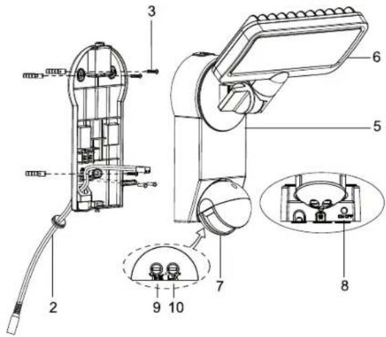
SOLAR LAMBANIN İLK KEZ ŞARJ EDİLMESİ
natural_image
Technical line drawing of a mechanical tool with a magnified inset showing a detail (no text or symbols)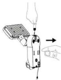
natural_image
Diagram of a handheld device with a hand holding a cable, showing mechanical components and an arrow indicating motion (no text or symbols present)Resim 1 Resim 2
Resim 3 Resim 4
natural_image
Technical line drawing of a robotic device with internal components and a separate view showing a close-up of its internal structure (no text or symbols present)Resim 5

Resim 6 Resim 7
natural_image
Diagram of a wall-mounted device with a sensor array and directional arrows indicating movement (no text or symbols)
natural_image
Technical diagram showing a wall-mounted air vent and its mechanical assembly with directional arrows (no text or symbols)Resim 11 Resim 12
Solar modülü:

natural_image
Technical line drawing of a mechanical component with a rotating shaft and housing (no text or symbols)Resim 8
Resim 9 Resim 10
natural_image
Technical line drawing of a wall-mounted electrical device with two components, mounted on a grid-patterned wall (no text or symbols)AYARLAMA VE DEVREYE SOKMA
AURINKOVALAISIMEN ENSIMMÄINEN LATAUS
natural_image
Technical line drawing of a pliers tool with a close-up inset showing the internal structure (no text or symbols)Kuva 1 Kuva 2

natural_image
Illustration of a hand using a handheld device to press or install a cable, with an arrow indicating action (no text or symbols present)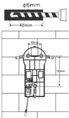
Kuva 3 Kuva 4
natural_image
Technical line drawing of a mechanical device with internal components and an external assembly (no text or symbols)Kuva 5
natural_image
Technical line drawing of a mechanical assembly with a hand holding a tool, showing internal components and alignment (no text or symbols)Kuva 6 Kuva 7
natural_image
Diagram of a mechanical device with rotating components and directional arrows, no text or symbols present
natural_image
Technical diagram showing a wall-mounted heating element and its mechanical assembly with directional arrows (no text or symbols)Kuva 11 Kuva 12
Aurinkomoduuli:
natural_image
Technical line drawing of a mechanical component with a rotating shaft and housing (no text or symbols)Kuva 8
Kuva 9 Kuva 10
natural_image
Diagram of a wall-mounted electrical meter with attached cable, showing wiring and components (no text or symbols)SÄÄTÖ JA KÄYTTÖÖNOTTO
natural_image
Technical line drawing of a mechanical clamp or tool with a magnified inset showing a detail (no text or symbols)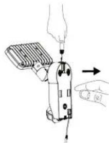
natural_image
Illustration of a hand using a screwdriver to adjust or install a mechanical component (no text or symbols visible)Εικόνα 1 Εικόνα 2
Εικόνα 3 Εικόνα 4
natural_image
Technical line drawing of a mechanical device with internal components and an arrow indicating assembly (no text or symbols)Εικόνα 5
natural_image
Technical line drawing showing two mechanical assembly steps with arrows indicating motion (no text or symbols)Εικόνα 6 Εικόνα 7
natural_image
Technical line drawing of a mechanical component with a rotating dial and handle (no text or symbols)Εικόνα 8
Εικόνα 9 Εικόνα 10

natural_image
Technical diagram showing a wall-mounted air vent and its mechanical assembly with directional arrows (no text or symbols)Εικόνα 11 Εικόνα 12
natural_image
Technical line drawing of a wall-mounted electrical meter with attached cables, mounted on a brick wall (no text or symbols)natural_image
Technical line drawing of a mechanical tool assembly (no text or symbols present)Рисунок 1 Рисунок 2
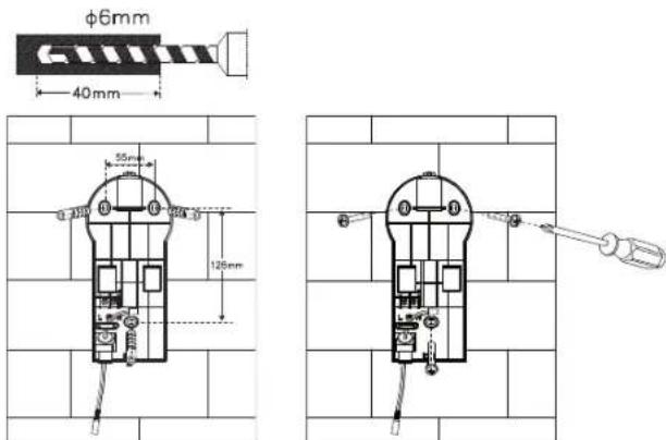
Рисунок 3 Рисунок 4
natural_image
Technical line drawing of a mechanical component with a rotating shaft and housing (no text or symbols)Рисунок 8
natural_image
Technical diagram showing a wall-mounted heating element connected to a vertical-mounted device, with directional arrows indicating motion (no text or symbols present)natural_image
Diagram of a wall-mounted device with two connected cables, mounted on a brick wall (no text or symbols)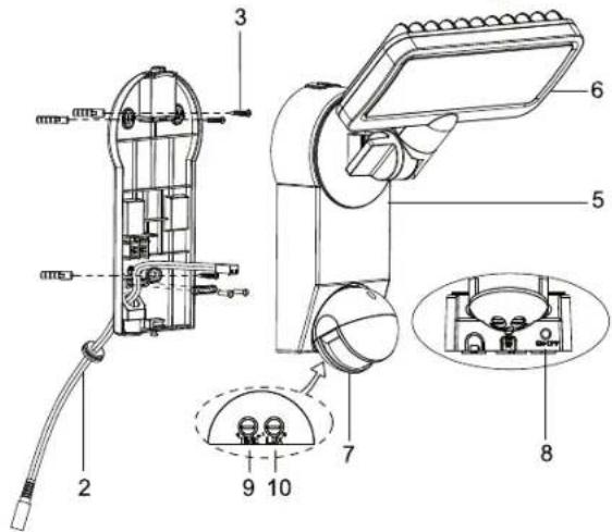
CARGA INICIAL DA LÂMPADA SOLAR
natural_image
Technical line drawing of a mechanical tool with a magnified inset showing a component (no text or symbols)
natural_image
Illustration of a hand using a handheld device to lift a screwdriver (no text or symbols present)Figura1 Figura 2
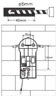
Figura 3 Figura 4
natural_image
Technical line drawing of a mechanical device with internal components and a separate view showing a close-up of its internal structure (no text or symbols present)Figura 5

Figura 6 Figura 7

natural_image
Diagram of a showerhead with water flow indicators (no text or symbols)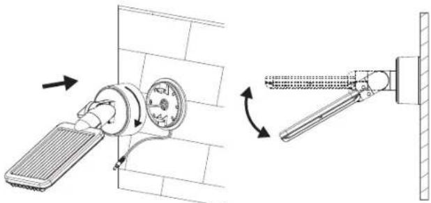
natural_image
Technical diagram showing a wall-mounted air vent and its mechanical assembly with directional arrows (no text or symbols)Figura 11 Figura 12
Módulo solar:

natural_image
Technical line drawing of a mechanical component with a rotating shaft and housing (no text or symbols)Figura 8
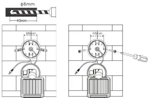
Figura 9 Figura 10
natural_image
Diagram of a wall-mounted handheld device with attached cable, mounted on a brick wall (no text or symbols)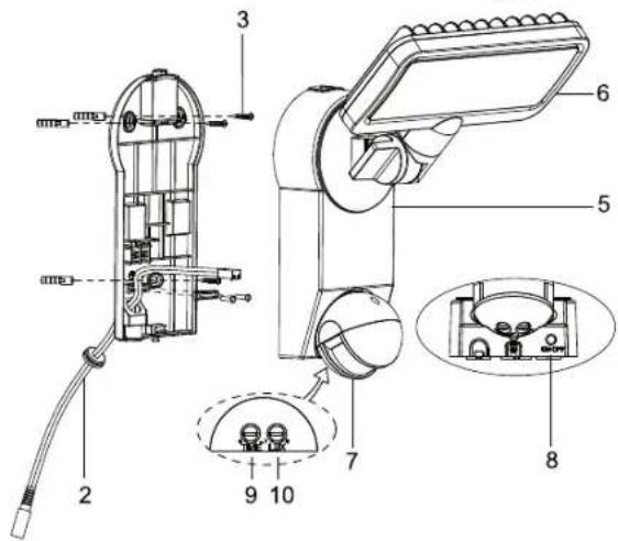
SOLAARVALGUSTI ESMAKORDNE LAADIMINE
natural_image
Technical line drawing of a mechanical tool assembly (no text or symbols present)Joonis 1 Joonis 2
Joonis 3 Joonis 4
natural_image
Technical line drawing of a mechanical device with internal components and an external assembly (no text or symbols)Joonis 5
Joonis 6 Joonis 7

natural_image
Diagram of a wall-mounted device with a sensor and directional arrows indicating movement (no text or symbols)
natural_image
Technical diagram showing a wall-mounted air vent and its mechanical assembly with directional arrows (no text or symbols)Joonis 11 Joonis 12
Solaarmoodul:

natural_image
Technical line drawing of a mechanical device with a rotating component (no text or symbols)Joonis 8
Joonis 9 Joonis 10
natural_image
Diagram of a wall-mounted electrical device with attached wires, no text or symbols present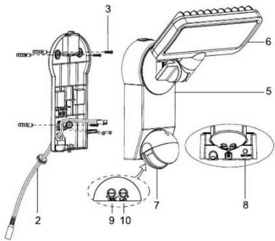
PRVÉ NABITIE SOLÁRNEJ LAMPY
natural_image
Technical line drawing of a mechanical clamp or tool with a magnified inset showing a small component (no text or symbols)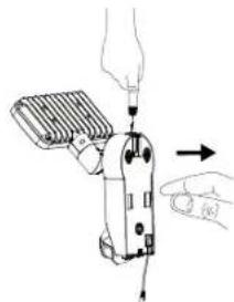
natural_image
Illustration of a handheld device with a hand inserting a plug into it, showing mechanical components and an arrow indicating motion (no text or symbols present)Obrázok1 Obrázok 2

Obrázok 3 Obrázok 4
natural_image
Technical line drawing of a mechanical device with internal components and wiring (no text or symbols)Obrázok 5
natural_image
Technical illustration of two mechanical assembly steps showing tool positioning and movement (no text or symbols)Obrázok 6 Obrázok 7
Solárny modul:

natural_image
Technical line drawing of a mechanical component with a rotating dial and housing (no text or symbols)Obrázok 8
natural_image
Technical diagram showing a wall-mounted air vent and its mechanical assembly with directional arrows (no text or symbols)natural_image
Diagram of two wall-mounted telephones with attached cables, mounted on a brick wall (no text or symbols)NASTAVENIE A SPUSTENIE DO PREVÁDZKY
PRVO POLNJENJE SOLARNE SVETILKE
natural_image
Technical line drawing of a pliers tool with a magnified inset showing a detail (no text or symbols)Slika 1 Slika 2

natural_image
Illustration of a hand using a handheld device to adjust or install a component, with no visible text or symbols.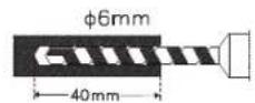
Slika 3 Slika 4
natural_image
Technical line drawing of a mechanical device with internal components and an external connector (no text or symbols)Slika 5

Slika 6 Slika 7
natural_image
Diagram of a wall-mounted device with a sensor and directional arrows indicating movement (no text or symbols)
natural_image
Technical diagram showing a wall-mounted heating element and its mechanical assembly with directional arrows (no text or symbols)Slika 11 Slika 12
Solarni modul:

natural_image
Technical line drawing of a mechanical component with a rotating shaft and housing (no text or symbols)Slika 8

Slika 9 Slika 10

natural_image
Diagram of two wall-mounted telephones with attached cables, mounted on a tiled wall (no text or symbols)NASTAVITEV IN PRVO DELOVANJE
(MOTNJA / VZROK → ODPRAVA)
SAULES GAISMEKŁA PIRMREIZĘJĄ UZLĄDE
natural_image
Technical line drawing of a mechanical clamp or tool with a magnified inset showing a small component (no text or symbols)1 attëls 2 attëls

natural_image
Illustration of a hand using a handheld device to adjust or install a component, with no visible text or symbols.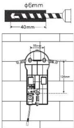
3 attêls 4 attêls
natural_image
Technical line drawing of a mechanical device with internal components and a separate view showing a close-up of a component (no text or symbols present)5 attëls

6 attêls 7 attêls

natural_image
Diagram of a mechanical device with directional arrows indicating motion or force (no text or symbols)
natural_image
Technical diagram showing a wall-mounted heating element and its mechanical assembly with directional arrows (no text or symbols)11 attêls 12 attêls
Saules bateriju modulis:

natural_image
Technical line drawing of a mechanical component with a rotating shaft and housing (no text or symbols)8 attêls

9 attêls 10 attêls
natural_image
Technical line drawing of a wall-mounted electrical meter with attached cable, no text or symbols presentIESTATĪŠANA UN LIETOŠANAS UZSĀKŠANA
PIRMASIS SAULĖS ENERGIJOS ŠVIESTUVO ĮKROVIMAS
natural_image
Technical line drawing of a mechanical tool with a magnified inset showing a detail (no text or symbols)1 pav. 2 pav.

natural_image
Illustration of a hand using a handheld device to interact with a finger, showing motion arrows (no text or symbols)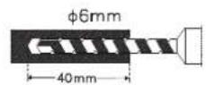
3 pav. 4 pav.

natural_image
Technical line drawing of a mechanical device with internal components and an external assembly (no text or symbols)5 pav.

6 pav. 7 pav.

natural_image
Diagram of a wall-mounted device with directional arrows indicating flow or movement (no text or symbols)
natural_image
Technical diagram showing a wall-mounted heating element and its mechanical assembly with directional arrows (no text or symbols)11 pav. 12 pav.
Saulès modulis:

natural_image
Technical line drawing of a mechanical component with a rotating dial and housing (no text or symbols)8 pav.

9 pav. 10 pav.
natural_image
Diagram of a wall-mounted electrical device with two connected cables, mounted on a brick wall (no text or symbols)NUSTATYMAS IR PALEIDIMAS


- ERSTMALIGES AUFLADEN DER SOLARLEUCHTE
- Solarmodul:
- GB INSTRUCTIONS FOR INSTALLATION AND USE
- PARTS LIST
- CHARGING THE SOLAR LIGHT FOR THE FIRST TIME
- SUITABLE LOCATIONS FOR INSTALLING THE SOLAR LIGHT AND THE SOLAR MODULE
- Main Unit:
- Installation:
- Solar Module:
- ADJUSTMENT AND INITIAL OPERATION
- Important:
- Adjusting the Motion Detector
- REPLACING THE BATTERY
- GENERAL SAFETY NOTES
- CLEANING
- STORAGE
- MALFUNCTIONS
- (FAILURE / CAUSE→REMEDY)
- Possible Solutions:
- SPECIFICATIONS:
- DISPOSAL
- Dispose of electrical devices in an environmentally responsible manner! Do not dispose of electrical devices with household rubbish.
- Improper disposal of batteries and rechargeable batteries damages the environment!
- FR MODE D'INSTALLATION ET D'EMPLOI
- PREMIER CHARGEMENT DE LA LAMPE SOLAIRE
- Module solaire :
- (TROUBLE / CAUSE →REMÈDE)
- EERSTE KEER OPLADEN VAN DE ZONNELAMP
- Zonnemodule:
- PRIMA CARICA DELLA LAMPADA SOLARE
- Modulo solare:
- FÖRSTA UPPLADDNINGEN AV SOLCELLSLAMPAN
- Solcellsmodulen:
- INSTÄLLNING OCH IDRIFTSTAGANDE
- PRIMERA CARGA DE LA LÁMPARA SOLAR
- Módulo solar:
- PIERWSZE LADOWANIE LAMPY SOLARNEJ
- Moduł solarny:
- USTAWIENIE I URUCHOMIENIE
- PRVNÍ NABITÍ SOLÁRNÍ LAMPY
- Solární modul:
- NASTAVENÍ A UVEDENÍ DO PROVOZU
- A NAPELEMES LÁMPA ELSŐ FELTÖLTÉSE
- Napelemes modul:
- SOLAR LAMBANIN İLK KEZ ŞARJ EDİLMESİ
- Solar modülü:
- AYARLAMA VE DEVREYE SOKMA
- AURINKOVALAISIMEN ENSIMMÄINEN LATAUS
- Aurinkomoduuli:
- SÄÄTÖ JA KÄYTTÖÖNOTTO
- CARGA INICIAL DA LÂMPADA SOLAR
- SOLAARVALGUSTI ESMAKORDNE LAADIMINE
- Solaarmoodul:
- PRVÉ NABITIE SOLÁRNEJ LAMPY
- Solárny modul:
- NASTAVENIE A SPUSTENIE DO PREVÁDZKY
- PRVO POLNJENJE SOLARNE SVETILKE
- Solarni modul:
- NASTAVITEV IN PRVO DELOVANJE
- (MOTNJA / VZROK → ODPRAVA)
- SAULES GAISMEKŁA PIRMREIZĘJĄ UZLĄDE
- Saules bateriju modulis:
- IESTATĪŠANA UN LIETOŠANAS UZSĀKŠANA
- PIRMASIS SAULĖS ENERGIJOS ŠVIESTUVO ĮKROVIMAS
- Saulès modulis:
- NUSTATYMAS IR PALEIDIMAS
Brand : BRENNENSTUHL
Model : SOL SH0805 P2
Category : Lighting