
0 607 561 118 - Saw BOSCH - Free user manual and instructions
Find the device manual for free 0 607 561 118 BOSCH in PDF.

| Product Type | Pneumatic Jigsaw |
| Brand | Bosch |
| Model | 0 607 561 118 |
| Weight | 1.8 kg (EPTA Procedure 01/2003) |
| Power Source | Compressed air (nominal pressure 6.3 bar / 91 psi) |
| Air consumption under load | 12.0 l/s (25.4 cfm) |
| Stroke rate | 2,200 min⁻¹ |
| Stroke | 26 mm |
| Max cutting depth (wood) | 85 mm (2-3/8 in) |
| Max cutting depth (plastic) | 30 mm (1-1/4 in) |
| Max cutting depth (aluminum) | 15 mm (3/4 in) |
| Max cutting depth (mild steel) | 10 mm (3/8 in) |
| Max cutting angle | 45° (adjustable in marked increments 0°, 15°, 30°, 45°) |
| Pendulum motion | 4 positions (0, I, II, III) |
| Blade change system | Tool-less SDS |
| Blade type | Single-cam shank (T-shank) |
| Switch | Lever switch (dead man's switch) |
| Safety equipment | Hand guard, chip guard |
| Air inlet connection | 1/4" NPT |
| Recommended hose inner diameter | 10 mm (3/8 in), max length 4 m |
| Sound level | 76 dB(A) (uncertainty K=3 dB, may exceed 85 dB(A)) |
| Vibration | 4.0 m/s² (uncertainty K=1.6 m/s²) |
| Maintenance and cleaning | Clean the air inlet filter regularly; grease the guide roller; after 150 hours of service, have the gear cleaned |
| Spare parts and repairability | Repair by Bosch authorized service center; use original parts; accessories available at www.bosch-pt.com |
Frequently Asked Questions - 0 607 561 118 BOSCH
User questions about 0 607 561 118 BOSCH
0 question about this device. Answer the ones you know or ask your own.
Ask a new question about this device
Download the instructions for your Saw in PDF format for free! Find your manual 0 607 561 118 - BOSCH and take your electronic device back in hand. On this page are published all the documents necessary for the use of your device. 0 607 561 118 by BOSCH.
USER MANUAL 0 607 561 118 BOSCH
Dr. Egbert Schneider Senior Vice President Engineering
Dr. Eckerhard Strötgen
Head of Product Certification

Read and understand all instructions. Failure to follow all instructions listed below may result in
electric shock, fire, and/or serious personal injury.
Save these instructions.
The terminology "Pneumatic Tool" or "Tool" used in the following text refers to the so-called air tool in these operating instructions.
Work area
Keep work area clean and well lit. Cluttered and dark areas invite accidents.
Do not operate tools in explosive atmospheres, such as in the presence of flammable liquids, gases, or dust. During operation of the tool, its accessory can create sparks that may ignite the dust or fumes.
Keep bystanders, children, and visitors away while operating a tool. Distractions can cause you to lose control.
Pneumatic safety
Use compressed air of Quality Class 5 in accordance with DIN ISO 8573-1 and a separate maintenance unit near the tool. The compressed air supplied should be free of foreign material and moisture to protect the tool from damage, contamination, and rust.
Check the connections and air supply lines. All maintenance units, couplers, and hoses should conform to the product specifications in terms of pressure and air volume. Too low a pressure impairs the functioning of the tool; too high a pressure can result in physical damage and personal injury.
Protect the hoses from kinks, restrictions, solvents, and sharp edges. Keep the hoses away from heat, oil, and rotating parts. Immediately replace a damaged hose. A defective air supply line may result in a wild compressed air hose and can cause personal injury. Raised dust or chips may cause serious eye injury.
Make sure that hose clamps are always tightened firmly. Loose or damaged hose clamps may result in uncontrolled air escape.
Personal safety
Stay alert, watch what you are doing, and use common sense when operating a tool. Do not use tool while tired or under the influence of drugs, alcohol, or medication. A moment of inattention while operating tools may result in serious personal injury.
Use safety equipment. Always wear eye protection. Safety equipment such as a dust mask, non-skid safety shoes, a hard hat, or hearing protection used for appropriate conditions will reduce personal injuries.
Avoid accidental starting. Be sure switch is off before connecting to the air supply. Carrying tools with your finger on the switch or connecting tools to the air supply with the switch on invites accidents.
Remove adjusting keys before turning the tool on. A key that is left attached to a rotating part of the tool may result in personal injury.
Do not overreach. Keep proper footing and balance at all times. Proper footing and balance enables better control of the tool in unexpected situations.
Dress properly. Do not wear loose clothing or jewelry. Keep your hair, clothing, and gloves away from moving parts. Loose clothes, jewelry, or long hair can be caught in moving parts.
If dust extraction and collection devices are installed, ensure these are connected and properly used. Use of these devices can reduce dust-related hazards.
Do not directly inhale the exhaust air. Avoid exposing the eyes to exhaust air. The exhaust air of the air tool may contain water, oil, metal particles, or contaminants that may cause personal injury.
Pneumatic tool use and care
Use clamps or other practical way to secure and support the workpiece to a stable platform. Holding the work by hand or against your body is unstable and may lead to loss of control.
Do not force tool. Use the correct tool for your application. The correct tool will do the job better and safer at the rate for which it is designed.
Do not use tool if switch does not turn it ON or OFF. Any tool that cannot be controlled with the switch is dangerous and must be repaired.
Disconnect the air hose from the air supply before making any adjustments, changing accessories, or storing the tool. Such preventive safety measures reduce the risk of starting the tool accidentally.
Store idle air tools out of the reach of children and do not allow persons unfamiliar with the air tool or these instructions to operate the air tool. Air tools are dangerous in the hands of untrained users.
Maintain air tools. Check for misalignment or binding of moving parts, breakage of parts, and any other condition that may affect the operation of the air tool. If damaged, have the air tool repaired before use. Many accidents are caused by poorly maintained air tools.
Keep the tool bits clean. Well cared for tool bits are easier to use and can be controlled better.
Use the air tool, accessories, and tool bits, etc., in accordance with these instructions and in the manner intended for the particular type of air tool, taking into account the working conditions and the work to be performed. Use of the air tool
for operations different from those intended could result in a hazardous situation.
Service
Have your air tool serviced by a qualified repair person using only identical replacement parts. This will ensure that the safety of the air tool is maintained.
2 SPECIFIC SAFETY RULES
AIR JIGSAW SAFETY

Avoid contact with a live wire. The tool is not insulated and contact with a live wire may result in electric shock.
Use suitable detectors to find hidden utility lines or call the local utility company for assistance. Contact with electric lines can lead to fire or electrical shock. Damaging a gas line can result in an explosion. Penetrating a water pipe will cause property damage or an electrical shock.
When removing a saw blade, avoid contact with skin and use proper protective gloves when grasping the blade or accessory. Saw blades and accessories may become hot during prolonged use.
Never use bent or damaged saw blades. Bent or dull saw blades may break or kick back.
When you install the saw blade, insure that the saw blade is seated in the groove of the roller guide. The grooved roller keeps the saw blade held securely in the tool.
Check that the saw blades are seated firmly in the tool before you connect the tool to the air supply. Saw blades that are not clamped properly in the appropriate holder may slip out and can cause damage to the workpiece or injury to you or others.
Position the tool on the workpiece only when the tool is switched on. Otherwise, there is the danger of a kickback when the teeth bind in the workpiece.
Keep your hands away from the cutting area. Do not reach underneath the workpiece. Contact with the saw blade may result in injury.
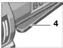
Take care during cutting to insure that the footplate 10 lies completely on the workpiece. A footplate that does not lie completely on the surface may result in breakage of the saw blade.
After cutting has been completed, switch off the air tool and withdraw the saw blade from the cut only when the saw blade has come to a complete stop. In this way, you avoid a kickback and can put down the air tool safely.
Do not brake the saw blade by applying side pressure against it after the tool is switched off. The saw blade may be damaged, may break, or may kick back.

Some dust created by power sanding, sawing, grinding, drilling, and other construction ac
tivities contains chemicals known to cause cancer, birth defects, or other reproductive harm.
Some examples of these chemicals are:
- Lead from lead-based paints,
- Crystalline silica from bricks and cement and other masonry products, and
- Arsenic and chromium from chemically treated lumber.
Your risk from these exposures varies, depending on how often you do this type of work. To reduce your exposure to these chemicals: work in a well-ventilated area, and work with approved safety equipment, such as those dust masks that are specially designed to filter out microscopic particles.
SYMBOLS
Important notice: Some of the following symbols could have meaning for the use of your tool. Please take note of the symbols and their meaning. The correct interpretation of the symbols will help you to use the tool in a better and safer manner.
Symbol Name Meaning
| W Hp | Watt Horsepower | Power |
| Nm ft-lbs | Newton-meter Foot-pounds | Unit of energy, torque |
| kg lbs | Kilograms Pounds | Mass, weight |
| mm in | Millimeter Inches | Length |
| min/s Minutes/seconds | Time | |
| bar/psi Bar/pounds per square inch Air pressure | ||
| l/s cfm | Liter per second Cubic feet/minute | Air consumption |
| °C/°F Degrees Celsius/Degrees Fahrenheit | Temperature | |
| dB Decibel Unit of relative loudness | ||
| Ø Diameter Size of drill bits, grinding wheels, etc. | ||
| min-1/n0Revolutions per minute/no load speed | Rotational speed at no load | |
| .../min Revolutions or reciprocations per minute | Revolutions, strokes, surface speed, orbits, etc. per minute | |
| 0 Off position | Zero speed, zero torque | |
| ΩΩ | Left rotation/right rotation | Direction of drive rotation |
| ○/■/UNF | Hex socket drive/square drive/ Unified National Fine | Type of tool holder |
| → | Arrow | Action in the direction of arrow |
| Warning symbol | Alerts user to warning messages. | |
| Symbol for directions | Gives instructions for correct handling – for example, read operating instructions or wear safety glasses. | |
3 FUNCTION
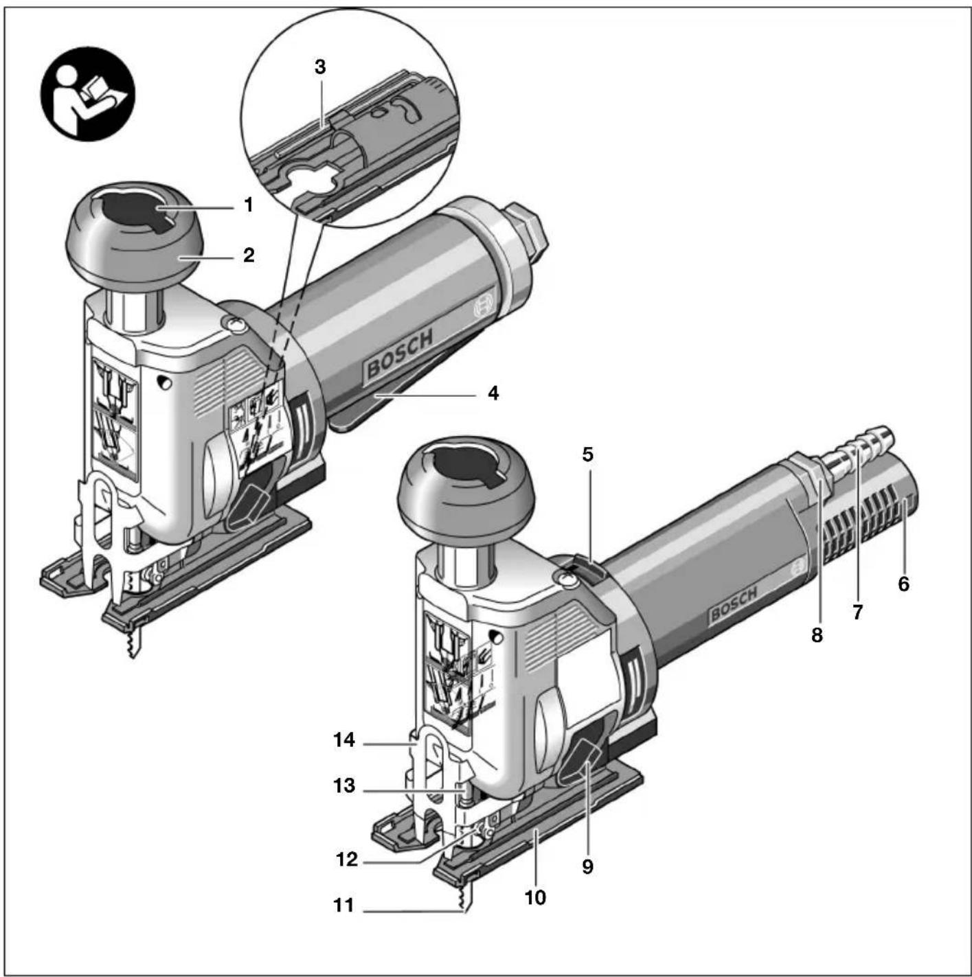
1 SDS blade change button
2 Barrel grip
3 Allen wrench in the footplate
4 On/Off switch (Lever switch)
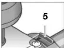
5 On/Off switch (Locking switch or Deadman switch)
6 Air outlet with muffler
7 Hose nipple
8 Air inlet connector
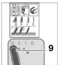
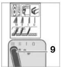
9 Orbit selector switch
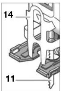
10 Footplate
11 Saw blade (Tool bit)
12 Roller guide
13 Blade Plunger
14 Safety cover
Not all the accessories illustrated or described are included in standard delivery.
Intended Use
The machine is intended for making cuts and cutouts in wood, plastic, metal, ceramic plates, and rubber while resting firmly on the workpiece. It is suitable for straight and curved cuts with bevel angles to 45^ . The saw blade recommendations are to be observed.
Noise/Vibration Information
Measured sound values determined in accordance with EN ISO 15744.
Measured vibration values determined in accordance with EN 28662 and EN ISO 8662.
Typically, the A-weighted sound pressure level of the product is 76 dB(A).
Measuring inaccuracy K = 3 dB.
The noise level when working can exceed 85 dB(A).
Wear ear protection!
The typically weighted acceleration is 4.0m / s^2 Measuring inaccuracy K = 1.6m / s^2
CE Declaration of Conformity
We declare under our sole responsibility that this product is in conformity with the following standards or standardization documents: EN 792, according to the provisions of the directive 98/37/EC.
Dr. Egbert Schneider Senior Vice President Engineering
Dr. Eckerhard Strotgen
Head of Product Certification

Product Specifications
Air JigSaw
| Part number 0 607 561 ... ... 114 ... 116 ... 118 ... 120 | ||||
| Power output W | 400 | 400 | 400 | 400 |
| Hp | 0.54 | 0.54 | 0.54 | 0.54 |
| Stroke rate min | 2400 | 2400 | 2200 | |
| Stroke length mm 26 26 26 26 | ||||
| Cutting depth capacity | ||||
| Wood mm | 85 | 85 | 85 | 85 |
| in | 2-3/8" | 2-3/8" | 2-3/8" | 2-3/8" |
| Plastic mm | 30 | 30 | 30 | 30 |
| in | 1-1/4" | 1-1/4" | 1-1/4" | 1-1/4" |
| Aluminum mm | 15 | 15 | 15 | 15 |
| in | 3/4" | 3/4" | 3/4" | 3/4" |
| Mild steel mm | 10 | 10 | 10 | 10 |
| in | 3/8" | 3/8" | 3/8" | 3/8" |
| Maximum Blade cutting angle (Orbiting action) 45° 45° 45° 45° | ||||
| Locking switch●- | - | |||
| Deadman switch | - | ●- | ||
| Paddle style switch | - | ● | ||
| Safety cover | ● | ● | ● | ● |
| Anti-splinter insert | ● | ● | ● | ● |
| Rated pressure bar/psi | 6.3/91 | 6.3/91 | 6.3/91 | 6.3/91 |
| Connecting thread | 1/4" NPT | 1/4" NPT | 1/4" NPT | 1/4" NPT |
| Hose inner diameter mm | 10 | 10 | 10 | 10 |
| in | 3/8" | 3/8" | 3/8" | 3/8" |
| Air consumption under load l/s | 12.0 | 12.0 | 12.0 | 12.0 |
| cfm | 25.4 | 25.4 | 25.4 | 25.4 |
| Weight in accordance with kg | 1.8 | 1.8 | 1.8 | 1.8 |
| EPTA-Procedure 01/2003 lbs | 3.3 | 3.3 | 3.3 | 3.3 |
4 MOUNTING
Saw Blade Recommendations
The jigsaw is delivered with different saw blades. Choose the saw blade that is appropriate for your work from the following table.
| ●specially suitable for Osuitable for | T 244 D | T 144 DP | T 123 X |
| Solid wood ●●- | |||
| Particle board ○ ● - | |||
| Plastic-coated / laminated wood fiberboard ○- - | |||
| Bonded wood / wood composite materials ○- - | |||
| PVC, general plastics ●- - | |||
| Metals - - ● | |||
| Sheet metal - - ● |
Note: Only T-shank type blades (Single Lug Shank) fit in this jigsaw.
Do not remove the safety cover!
The safety cover 14 attached to the housing prevents accidental contact with the saw blade 11 during operation.
Installing the Saw Blade
Disconnect the air hose from the air supply before making any adjustments, changing accessories, or storing the tool. Such preventive safety measures reduce the risk of starting the tool accidentally.

The Bosch SDS system provides a simple and convenient way to change saw blades without any tools.
When removing a saw blade, avoid contact with skin and use proper protective gloves when grasping the blade or accessory. Saw blades and accessories may become hot during prolonged use.
To install the saw blade, set the orbit selector switch 9 to setting III. This position provides the easiest insertion access for the saw blade.
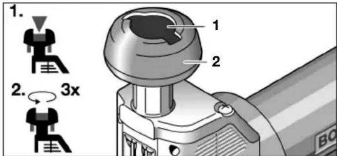
Push the orange-colored SDS blade change button 1 downward. This unlocks the barrel grip 2.
Turn the barrel grip 2 approximately three turns counterclockwise.
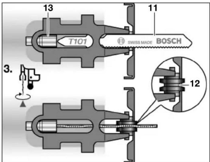
Insert the saw blade 11 into the opening of the plunger 13 perpendicular to the cutting direction. There are two small grooves in the blade plunger into which the "T-tabs" on the blade fit precisely. Turn the saw blade 11 90^ in the cutting direction and push it into the groove of the roller guide 12. The saw teeth should now point towards the front of the saw. Pull the saw blade 11 slightly downward.
Turn the barrel grip 2 clockwise until you hear the locking mechanism engage or "click" a few times. Pull the orange-colored SDS blade change button 1 back up. This locks the barrel grip in place.
Check that the saw blades are seated firmly in the tool before you connect the tool to the air supply. Saw blades that are not clamped properly in the appropriate holder may slip out and can cause damage to the workpiece or injury to you or others.
Exhaust Line
You can use an exhaust line to carry exhaust air away from your workplace and, at the same time, achieve optimal muffling. You also improve the operating conditions, because your workplace will no longer be contaminated by oil-containing air and there are no longer any raised dust or chips.
Type 0 607 561 114 / ... 116
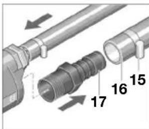
Unscrew the muffler at the air outlet 6 and replace it with the hose nipple 17.
Loosen the hose clamp 15 of the exhaust hose 16 and attach the exhaust hose over the hose nipple 17 by firmly tightening the hose clamp.
Type 0 607 561 118 / ... 120
Variant 1: Slip the exhaust hose (combined) 18, which carries the exhaust air away from your workplace, over the air inlet hose 19. Then connect the tool to the air supply (see section Connection to the Air Supply) and pull the exhaust hose (com
binned) 18 over the mounted air inlet hose to the end of the tool.
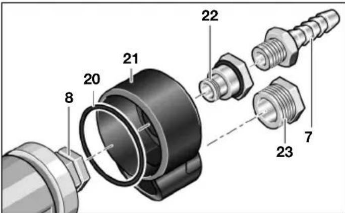
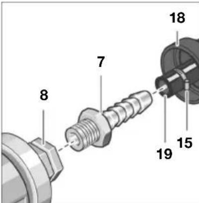
Variant 2: Route the exhaust air away from the area by attaching an exhaust assembly (decentralised) 21. Make sure that the hose nipple 7 is not screwed into the connector at the air inlet 8 and that the O-ring 20 lies in the recess between the housing and the exhaust assembly, so that the exhaust air can only escape to the exhaust hose. Tightly screw first the connector 22 of the exhaust assembly into the connector 8 at the air inlet and then the hose nipple 7 into the connector 22. Replace the muffler 23 on the exhaust assembly with the hose nipple 17 of the exhaust assembly.
Loosen the hose clamp 15 of the exhaust hose 16 and attach the exhaust hose over the hose nipple 17 by firmly tightening the hose clamp.
Connection to the Air Supply
The air tool is designed for an operating pressure of 6.3 bar (91 psi). For maximum performance, the inner diameter of the hose is 10mm with connection threads of 1/4'' NPT. To maintain full performance, use only hoses with a maximum length of 4m .
The supplied air must be free of foreign material and moisture to protect the air tool from damage, contamination, and rust.
The use of a compressed air maintenance unit is necessary.
This ensures optimum functioning of compressed air tools. Observe the operating instructions of the maintenance unit.
All fittings, connecting lines, and hoses must be dimensioned for the required air pressure and volume.
Avoid restrictions in the air supply resulting from, e.g., pinching, kinking, or stretching!
In case of doubt, measure the pressure with a pressure gauge at the air inlet with the tool switched on.
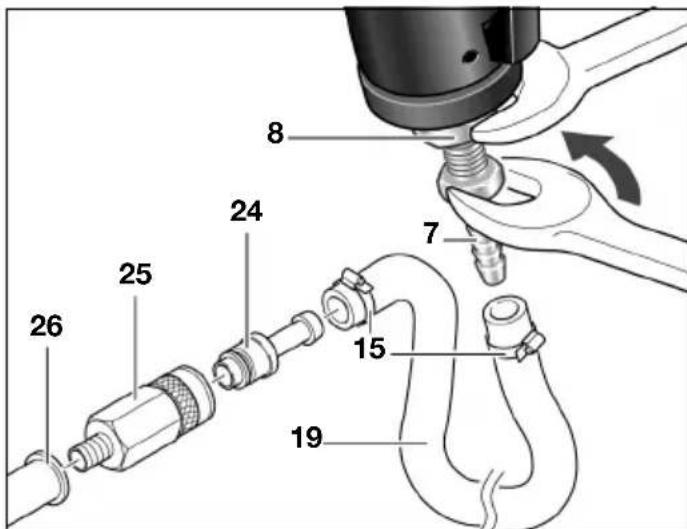
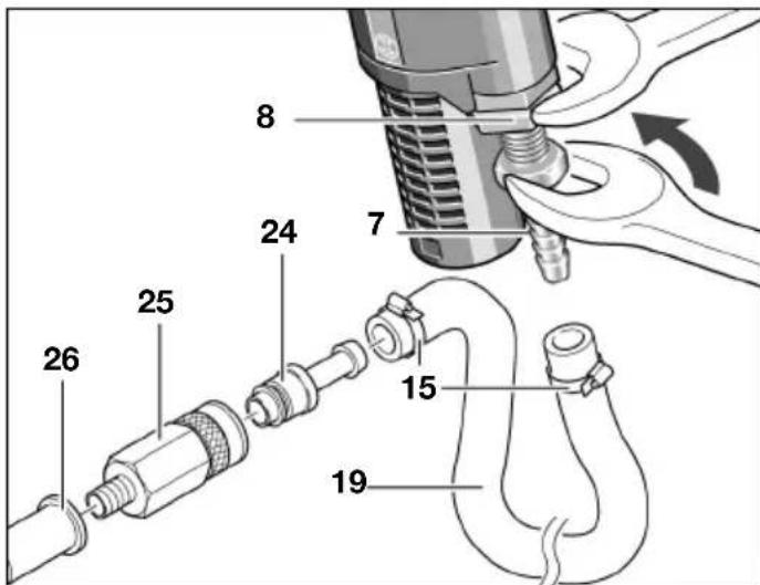
Connection of the Air Supply to the Air Tool Type 0 607 561 118 / ... 120
Screw the hose nipple 7 into the connector at the air inlet 8. To prevent damage to the internal valve components of the tool, you should use an open end wrench (22mm) to apply a counterforce at the protruding connector of the air inlet 8 when screwing/unscrewing the hose nipple 7.
Loosen the hose clamps 15 of the air inlet hose 19 with a maximum length of 4m and attach the air inlet hose over the hose nipple 7 by firmly tightening the hose clamp.
Always connect the air inlet hose 19 first to the tool, then to the maintenance unit.
Slip the air inlet hose 19 over the coupling nipple 24 and attach the air inlet hose by firmly tightening the hose clamp 15.
Screw a quick hose connector 25 into the air outlet of the maintenance unit 26. Quick hose connectors make possible a quick connection and, when uncoupled, they shut off the air supply automatically.
Take care that you do not start the tool accidentally when you insert the coupling nipple 24 into the coupler 25.
Type 0 607 561 114 / ... 116
Screw the hose nipple 7 into the connector at the air inlet 8. To prevent damage to the internal valve components of the tool, you should use an open end wrench (22mm) to apply a counterforce at the protruding connector of the air inlet 8 when screwing/un-screwing the hose nipple 7.
When you use the exhaust assembly, screw the hose nipple 7 into the connector 22 of the exhaust assembly (decentralised) 21.
Loosen the hose clamps 15 of the air inlet hose 19 with a maximum length of 4m and attach the air inlet hose over the hose nipple 7 by firmly tightening the hose clamp.
Always connect the air inlet hose 19 first to the tool, then to the maintenance unit.
Slip the air inlet hose 19 over the coupling nipple 24 and attach the air inlet hose by firmly tightening the hose clamp 15.
Screw a quick hose connector 25 into the air outlet of the maintenance unit 26. Quick hose connectors make possible a quick connection and, when uncoupled, they shut off the air supply automatically.
Take care that you do not start the tool accidentally when you insert the coupling nipple 24 into the coupler 25.
5 OPERATING INSTRUCTIONS
Blade Orbiting Action

You can optimize the cutting speed, cutting power, and the appearance of the cut to match the material being cut by using the blade orbit selector switch, which has four adjustable settings. When the tool is in operation, you can also use the orbit selector switch 9 to change the blade orbit in steps:
Setting 0: no orbit
Setting I: small orbit
Setting II: medium orbit
Setting III: large orbit
Recommendation:
-
The finer and cleaner the cut desired, the lower the orbit setting (zero). The faster and rougher the cut desired, the higher the orbit setting (three).
-
When cutting thin workpieces (like sheet metal) or when a blade knife is used, you should switch off the orbit action.
-
Hard workpieces (e.g., nonferrous metals like brass or copper) may be cut with a small blade orbit.
-
Hard wood and plastic may be cut with a medium blade orbit.
- Soft materials (e.g., soft woods) or ripping (cutting with the grain) may be cut with a large blade orbit.
Putting into Operation
The air tool operates optimally with a pressure of 6.3 bar (91 psi) measured at the air inlet with the tool running.
Switching On/Off

In the event of an interruption of the air supply or reduced operating pressure, switch off the tool. Check the operating pressure and start again when the pressure returns to normal.
Type 0 607 561 114 Locking switch
Switching on:
Slide the on/off switch 5 forward
Switching off:
Slide the on/off switch 5 backward to release the locking mechanism and to switch off the tool.
Type 0 607 561 116 Deadman switch
Switching on: Press the on/off switch 5 and keep it pressed down during the operation.
Switching off: Release the on/off switch 5.
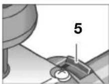
Type 0 607 561 118 / ... 120 Paddle style switch
Switching on:
Press the lever switch 4 and keep it pressed down during the operation.
Switching off:
Release the lever switch 4.
Removing the Saw Blade
Disconnect the air hose from the air supply before making any adjustments, changing accessories, or storing the tool. Such preventive safety measures reduce the risk of starting the tool accidentally.
When removing a saw blade, avoid contact with skin and use proper protective gloves when grasping the blade or accessory. Saw blades and accessories may become hot during prolonged use.
To remove the saw blade, set the orbit selector switch 9 to setting III. This position provides the easiest removal access for the saw blade.
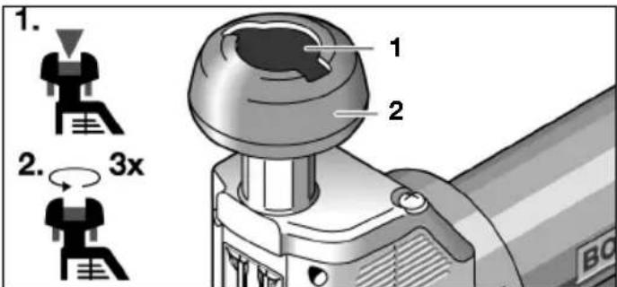
Push the orange-colored SDS blade change button 1 downward. This unlocks the barrel grip 2.
Turn the barrel grip 2 approximately three turns counterclockwise.
Push the saw blade 11 gently in the directly of the barrel grip, turn it 90^ , and pull it out of the plunger 13.
Working Instructions
Disconnect the air hose from the air supply before making any adjustments, changing accessories, or storing the tool. Such preventive safety measures reduce the risk of starting the tool accidentally.
Excess loads that cause the tool to stall or reduce speed will not damage the motor.

In the event of an interruption of the air supply or reduced operating pressure, switch off the tool. Check the operating pressure and start again when the pressure returns to normal.
Use a saw blade that is appropriate for the thickness of the workpiece. In its highest point of up-and-down stroke, the saw blade should project at least 10% beyond the thickness of the workpiece. This insures that the saw blade will not bind in the workpiece and will help you achieve precise, clean cuts.
Note that too high a feed rate reduces the output capacity substantially and shortens the life of the saw blades. Sharp tool bits provide good cutting power and protect the tool.
Always use a stable support or a bench when small or thin workpieces are being cut. Thin workpieces may bend or vibrate during cutting and may no longer be controllable.
Adjusting the Bevel
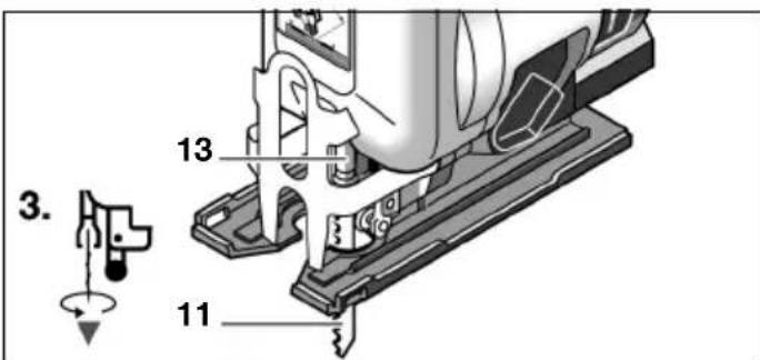
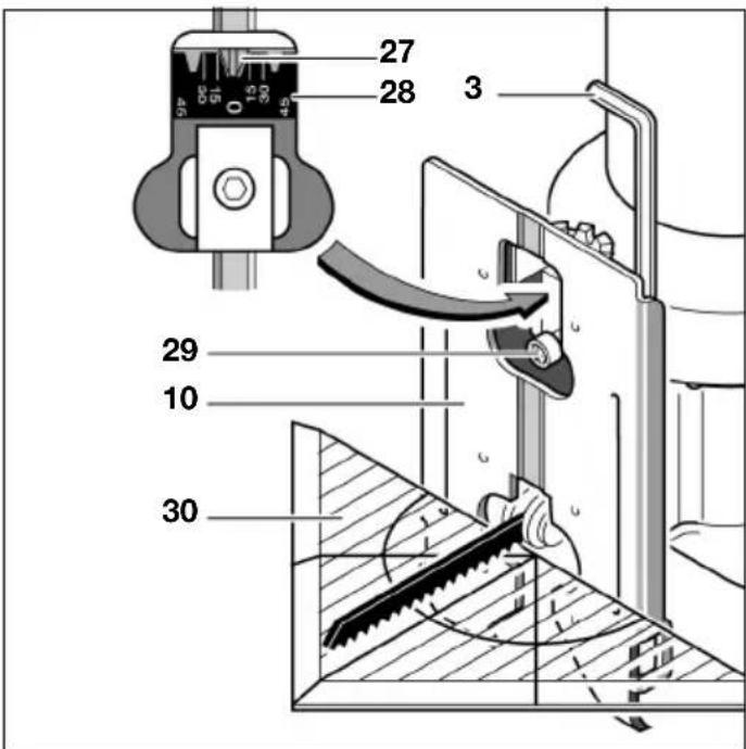
The footplate 10 can be adjusted to change the bevel up to 45^ .
Loosen the locking screw 29 by unscrewing it several turns counterclockwise using the Allen wrench 3, which is located in the footplate 10. Slide the footplate 10 in the direction of the saw blade and pivot it to the right or to the left, depending on the desired bevel.
After the bevel has been rough adjusted, snug down the locking screw 29 until it is still just barely possible to shift the footplate 10. Adjust the bevel precisely.
Bevels of 0^ , 15^ , 30^ , and 45^ are indicated with markings on the bevel scale 28 Intermediate adjustments are also possible. For exact bevels, you should employ a protractor 30. Tighten the locking screw 29 by using the Allen wrench 3.
You can adjust the 0^ position (saw blade perpendicular) by sliding the footplate 10 toward the rear of the tool until it is caught in a detent notch 27. Slide the footplate 10 in the direction of the motor against the detent notch 27 and tighten the locking screw 29.
Flush Cutting
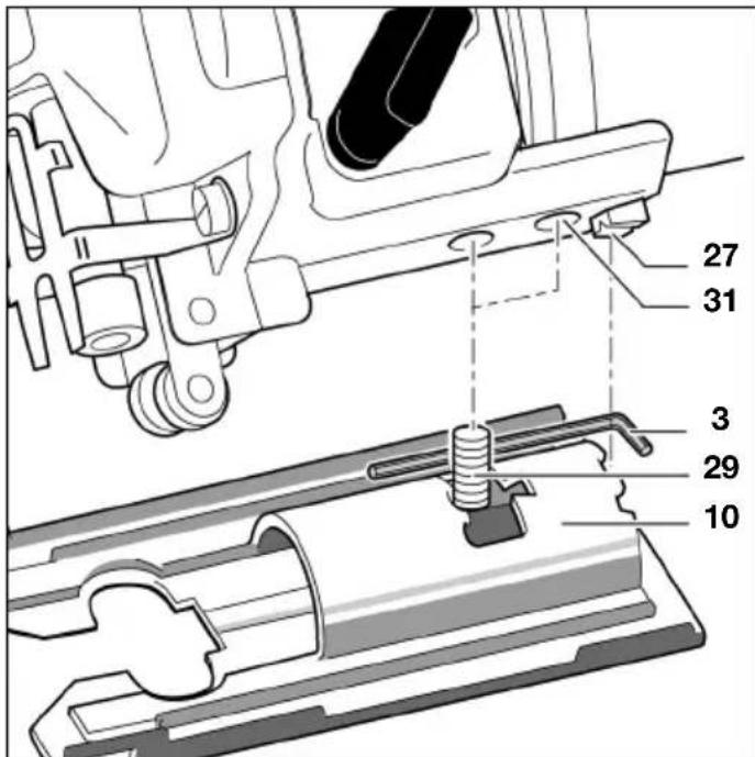
For flush cutting, you can reposition the footplate 10 toward the back of the tool:
Completely unscrew the locking screw 29 in the counterclockwise direction by using the Allen wrench 3, which is located in the footplate 10. Lift up the footplate 10 and reposition it toward the back of the tool so that you can screw the locking screw 29 into the rear thread 31. Tighten the locking screw 29 at first only slightly, slide the footplate 10 in the direction of the saw blade, and then tighten the locking screw firmly.
Flush cutting can be performed only with a perpendicular saw blade (0^ position). It is not possible in this case to use the parallel guide with circle jig 34.
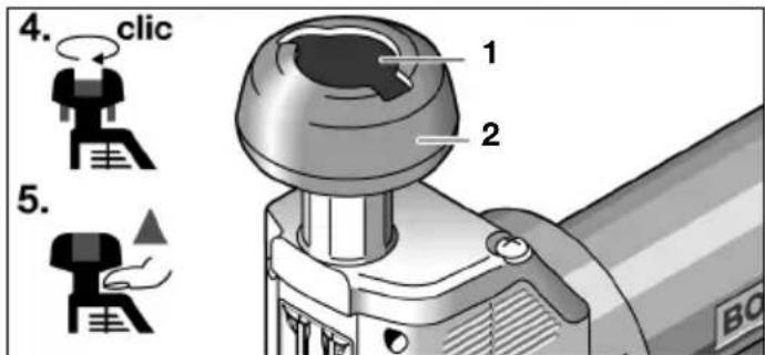
Note: For easier cutting in very tight places, you can remove the barrel grip 2:
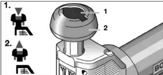
Push the orange-colored SDS blade change button 1 downward over the locking point and simultaneously pull the barrel grip 2 upward away from the tool.
To reinstall the hand grip:
Push the SDS blade change button 1 upward into the initial position. Set the hand grip 2 back in place and press it downward with (if needed) a slight twist until you hear it lock in place.
Parallel Cuts
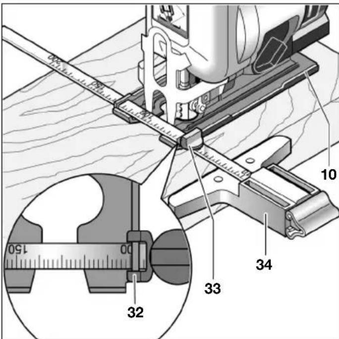
You can make parallel cuts up to a material thickness of 30mm (1.2 inches) by using the parallel guide with circle jig 34.
Loosen the locking screw 33 and slide the scale through the cutting guide slot 32 in the footplate 10. Slide the scale through the cutting guide slot as far as needed for the separation of the parallel cut. Use the scale value on the inner edge of the footplate as your guide. Parallel cuts of up to 20cm separation are possible. Tighten the locking screw 33 at the desired scale value.
Circle Jig
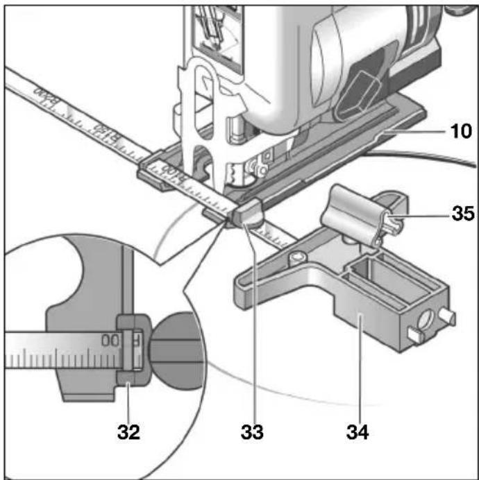
You can make circular cuts up to a material thickness of 30mm (1.2 inches) by using the parallel guide with circle jig 34.
Remove the locking screw 33 and flip the parallel guide. Reinstall the locking screw on the other side. Slide the scale through the cutting guide slot 32 of the footplate 10. Pull off the centering tip 35 and place it into the opening at the level of the saw blade. Bore a hole in the center of the cutout in order to fix the centering tip 35 in place and adjust the radius on the inner edge of the footplate 10 by using the locking screw 33.
Note: For tight curves, it is best to use narrow saw blades.
Anti-Splinter Insert
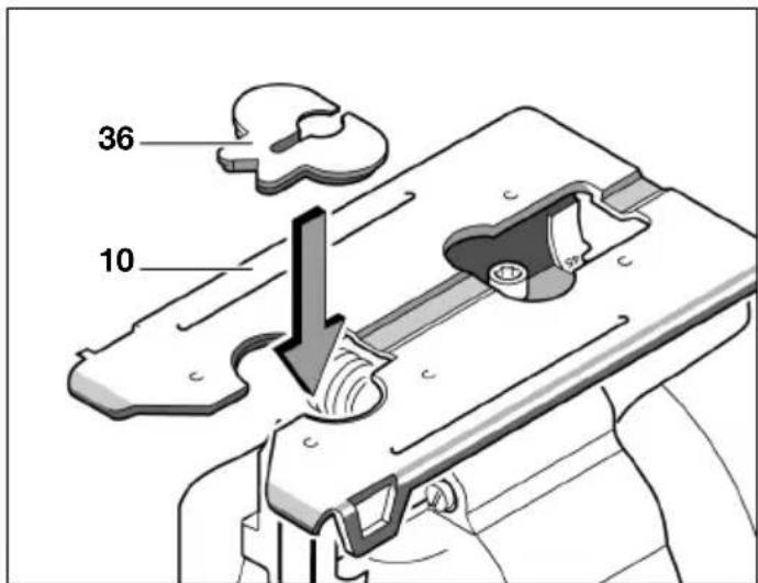
The anti-splinter insert 36 reduces splintering of the work piece surface during cutting.
Press the anti-splinter insert 36 into the footplate 10 from below. You may use the anti-splinter insert 36 for the following types of saw blades: T 101 B, T 101 D, T 244 D, T 301 CD, T 301 DL.
Cooling and Lubricating work pieces
When cutting metal, consider applying a coolant or lubricant along the line of cut to reduce any heat that is generated by the cutting process.
6 MAINTENANCE AND SERVICE
Maintenance
Disconnect the air hose from the air supply before making any adjustments, changing accessories, or storing the tool. Such preventive safety measures reduce the risk of starting the tool accidentally.
Should the tool fail in spite of careful manufacturing and testing procedures, have the repairs performed by an authorized customer service location for Bosch power tools.
For inquiries and spare parts ordering, please include the 10-digit order number on the nameplate of the tool.
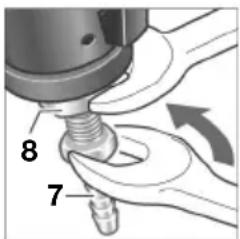
Clean the screen of the air inlet regularly. For this purpose, unscrew the hose nipple 7 and remove dust and dirt particles from the screen. Then firmly remount the hose nipple.
valve components of the tool, you should use an open end wrench (22 mm) to apply a counterforce at the protruding connector of the air inlet 8 when screwing/unscrewing the hose nipple 7.

Water and dirt particles in the compressed air cause rust formation and lead to clogging of vanes, valves, etc. To prevent this, a few drops of motor oil should be placed in the air inlet 8. Reconnect the tool to the air supply and
let the tool run for 5-10 s while catching the oil that runs out with a rag. If the air tool is not used for a longer time, this procedure should always be performed.
All Bosch air tools that do not belong to the CLEAN series (a special kind of air motor that functions with oil-free compressed air), require a small amount of lubricating oil be mixed into the flow of compressed air. The compressed air oiler required for this is located at the compressed air maintenance unit connected to the tool (you may obtain further details on this from a compressor manufacturer).
Occasionally lubricate the roller guide 12 with a drop of oil and inspect it for any wear. If the roller guide 12 is worn, it should be replaced by an authorized Bosch service center for air tools and electric power tools.
You should use SAE 10 or SAE 20 motor oil for direct lubrication of the tool or for admixture at the maintenance unit (compressor).
After the first 150 hours of operation, the gearbox should be cleaned and lubricated by an authorized service center. This process should be then performed after every 300 hours of operation. After each cleaning, it should be lubricated with special gearbox grease.
Special gearbox grease 225 ml . . . . 3 605 430 009
The motor vanes should be routinely inspected by trained personnel and, if necessary, replaced.
Have maintenance and repair work performed only by qualified specialists. In this manner, it can be ensured that the safety of the tool is maintained.
Any Bosch customer service center can perform this work quickly and reliably.
Dispose of lubricants and cleaning agents in an environment-friendly manner. Comply with the legal regulations.
Accessories
Various saw blades are available for all jigsaws.
Information about the complete quality accessory program can be found on the Internet at
www.bosch-pt.com and
www.boschproductiontools.com or at your dealer.
Service
Robert Bosch GmbH is responsible for the delivery of the tool in accordance with the sales contract within the framework of the legal/country-specific regulations. For claims with respect to the tool, please contact the following location:
Fax 49 (711) 7582436
www.boschproductiontools.com
Disposal
Tool, accessories, and packaging should be sorted for environment-friendlyly recycling.
The plastic components are labeled for categorized recycling.
If your tool can no longer be used, deliver it to a recycling center or return it to a dealer - for example, an authorized Bosch service center.
Specifications subject to change without notice
1 CONSIGNES GENÉRALES DE SECURITÉ POUR OUTILLAGES PNEUMATIQUES
A VERTISSEMENT
VousdezlireetcomPRENDetoulesinstructions.Le non-respect,
Dr. Egbert Schneider Senior Vice President Engineering
Dr. Eckerhard Ströttgen
Head of Product Certification

Dr. Egbert Schneider Senior Vice President Engineering
Dr. Eckerhard Ströttgen
Head of Product Certification

Con el tope paralelo con cortador de circulos 34 seSEOSEOSEOSEOSEOSEOSEOSEOSEOSEOSEOSEOSEOSEOSEOSEOSEOSEOSEOSEOSEOSEOSEOSEOSEOSEOSEOSEOSEOSEOSEOSEOSEOSEOSEOSEOSEOSEOSEOSEOSEOSEOSEOSEOSEOSEOSEOSEOSEOSEOSEOSEOSEOSEOSEOSEOSEOSEOSEOSEOSEOSEOSEOSEOSEOSEOSEOSEOSEOSEOSEOSEOSEOSEOSEOSEOSEOSEOSEOSEOSEOSEOSEOSEOSEOSEOSEOSEOSEOSEOSEOSEOSEOSEOSEOSEOSEOSEOSEOSEO SEOEO SEOEO SEOEO SEOEO SEOEO SEOEO SEOEO SEOEO SEOEO SEOEO SEOEO SEOEO SEOEO SEOEO SEOEO SEOEO SEOEO SEOEO SEOEO SEOEO SEOEO SEOEO SEOEO SEOEO SEOEO SEOEO SEOEO SEOEO SEOEO SEOEO SEOEO SEOEO SEOEO SEOEO SEOEO SEOEO SEOEO SEOEO SEOEO SEOEO SEOEO SEOEO SEOEO SEOEO SEOEO SEOEO SEOEO SEOEO SEOEO SEOEO SEOEQ
Dr. Egbert Schneider Senior Vice President Engineering
Dr. Eckerhard Strotgen
Head of Product Certification

Dr. Egbert Schneider Senior Vice President Engineering
Dr. Eckerhard Strotgen
Head of Product Certification

Dr. Egbert Schneider Senior Vice President Engineering
Dr. Eckerhard Strotgen
Head of Product Certification

Senior Vice President
Engineering
Dr. Eckerhard Strötgen
Head of Product
Certification

Senior Vice President
Engineering
Dr. Eckerhard Strötgen
Head of Product
Certification
Steg I: liter pending
Steg II: medelstor pending
Steg III: stor pending
Rekommendation:
Dr. Egbert Schneider Senior Vice President Engineering
Dr. Eckerhard Strotgen
Head of Product Certification

6 SERVICE OG VEDLIKEHOLD
Vedlikehold
Senior Vice President
Engineering
Dr. Eckerhard Strötgen
Head of Product
Certification

Dr. Egbert Schneider Senior Vice President Engineering
Dr. Eckerhard Strotgen
Head of Product Certification

Dr. Egbert Schneider Senior Vice President Engineering
Dr. Eckerhard Ströttgen
Head of Product Certification
