
GTA 2500 W Professional - Saw BOSCH - Free user manual and instructions
Find the device manual for free GTA 2500 W Professional BOSCH in PDF.

 FR
FR
 BG
BG
 CS
CS
 DA
DA
 DE
DE
 EL
EL
 EN
EN
 ES
ES
 ET
ET
 FI
FI
 HU
HU
 IT
IT
 KK
KK
 KO
KO
 LT
LT
 LV
LV
 MK
MK
 NL
NL
 NO
NO
 PL
PL
 PT
PT
 RO
RO
 RU
RU
 SK
SK
 SL
SL
 SV
SV
 TR
TR
 UK
UK
| Product type | Radial miter saw |
| Brand | Bosch |
| Model | GTA 2500 W Professional |
| Rated power | 2500 W |
| Blade diameter | 254 mm |
| No-load speed | 4500 rpm |
| Cutting capacity at 90° (H x W) | 127 x 340 mm |
| Cutting capacity at 45° (H x W) | 127 x 240 mm |
| Weight | 28 kg |
| Dimensions (L x W x H) | 680 x 500 x 630 mm |
| Power supply | 230 V / 50 Hz |
| Main functions | Miter cuts, bevel cuts, depth stop, guide laser |
| Maintenance and cleaning | Clean ventilation slots, check power cable, replace carbon brushes |
| Safety | Safety switch, protective guard, blade brake, circuit breaker |
| Spare parts | Blade, carbon brushes, guard, stop |
| Repairability | Repairability index: 8.2/10 |
| Included accessories | Blade, dust bag, blade wrench |
| Noise level | 98 dB(A) |
Frequently Asked Questions - GTA 2500 W Professional BOSCH
User questions about GTA 2500 W Professional BOSCH
0 question about this device. Answer the ones you know or ask your own.
Ask a new question about this device
Download the instructions for your Saw in PDF format for free! Find your manual GTA 2500 W Professional - BOSCH and take your electronic device back in hand. On this page are published all the documents necessary for the use of your device. GTA 2500 W Professional by BOSCH.
USER MANUAL GTA 2500 W Professional BOSCH
GTA 2500 W Professional
Robert Bosch Power Tools GmbH
70538 Stuttgart
GERMANY
www.bosch-pt.com
1 609 92A 6JB (2021.05) PS / 132

1 609 92A 6JB
natural_image
3D rendering of a mechanical support structure with no visible text or symbols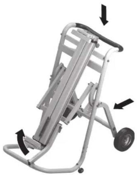
natural_image
Mechanical lift platform with visible frame and wheel, showing directional arrows indicating motion (no text or symbols)

natural_image
Mechanical assembly diagram showing a ladder-like structure with a central wheel and labeled dimension 'X' (no text or symbols beyond label)
natural_image
Mechanical assembly diagram showing a bracket with labeled component (24) and directional arrow (no readable text or symbols)10
H

[Non-Text]
J

| 11
natural_image
Mechanical assembly diagram showing a bracket with mounting holes and a labeled component (11), no readable text or symbols present.



Deutsch
Sicherheitshinweise
www.bosch-pt.com/serviceaddresses
Entsorgung
General Safety Instructions

Read all the warnings and instructions included with the saw stand or the power tool you intend to mount on it. Failure to observe the safety information and follow instructions may result in electric shock, fire and/or serious injury.
Safety Instructions for Saw Stands
▶ Disconnect the plug from the power source and/or remove the battery from the power tool before making
16 | English
any adjustments to the power tool or changing accessories. Accidents can occur when power tools are started unintentionally.
▶ Assemble the saw stand properly before mounting the power tool. Correct assembly is important to prevent the risk of collapsing.
▶ Firmly secure the power tool to the saw stand before using it. You may lose control of the power tool if it slips on the saw stand.
▶ Place the saw stand on a firm, flat, horizontal surface. If there is a chance that the saw stand will slip or wobble, the safe and steady machining of the workpiece cannot be guaranteed.
▶ Do not overload the saw stand or climb or stand on it. Overloading or standing on the saw stand can raise its centre of gravity, causing it to tip over.
▶ Ensure that all screws and connecting pieces are tightly fastened during transport and when carrying out work. Loose connections can cause instability and inaccurate sawing.
▶ Only install and remove the power tool when it is in the transport position (for information on the transport position, also refer to the operating instructions for the relevant power tool). Otherwise the power tool may have an such unfavourable centre of gravity that you will not be able to hold onto it securely.
▶ Operate the power tool secured to the mounting plate on the saw stand only. Without the saw stand, the mounting plate with the power tool will not be stable and can tip over.
▶ Ensure that long and heavy workpieces do not unbalance the saw stand. The free end of long and heavy workpieces must have something placed underneath it or be supported.
▶ When pushing together or pulling apart the saw stand, do not put your fingers near the points of articulation. There is a risk of fingers being crushed.
Symbols
The following symbols may provide you with important information about the use of your saw stand. Please take note of these symbols and their meaning. Knowing what these symbols mean will help you to use your saw stand more effectively and more safely.
Symbols and their meaning
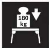
The maximum load bearing capacity (power tool + workpiece) of the saw stand is kg.
Product description and specifications
Intended Use
The saw stand is intended for holding the following Bosch benchtop saws (stand 2021.02):
- GCM 8 S (3 601 L16 0..)
-GCM 8 SJ (3 601 L16 2..)
- GCM 800 S (3 601 L16 1..)
- GCM 10 (0 601 B20 0..)
- GCM 10 J (3 601 M20 2..)
-GCM 10 M (3 601 M20 2..)
- GCM 10 S (0 601 B20 5..)
- GCM 10 SD (0 601 B22 5..)
- GCM 10 X (3 601 M15 0..)
- GCM 10 MX (3 601 M29 0..)
-GCM 12 (0 601 B21 0..)
-GCM 12 GDL (3 601 M23 6..)
- GCM 12 SD (0 601 B23 5..)
- GCM 216 (3 601 M33 0..
-GCM 18V-216(3601M410..)
- GCM 18V-305 GDC (3 601 M43 0..)
-GTM 12 (3 601 M15 0..)
The saw stand and power tool are intended for cutting boards and profiles.
Product Features
The numbering of the components shown refers to the illustrations on the graphics pages at the beginning of the manual.
(1) Holder set
(2) Saw stand
(3) Wheel locking mechanism
(4) Table extension locking knob
(5) Table extension
(6) Handle
(7) Height-adjustable foot
(8) Saw stand support
(9) Support locking mechanism
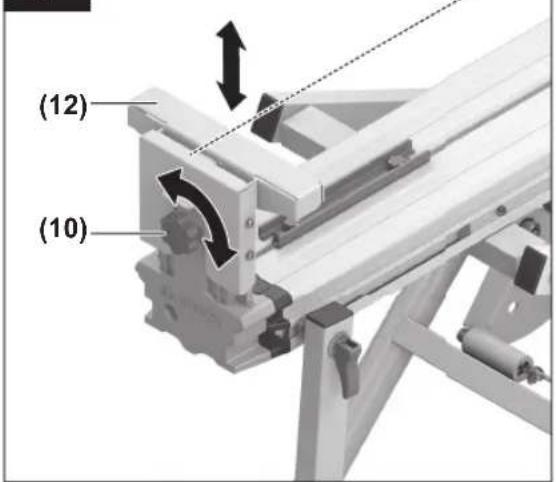
(10) Workpiece support locking knob
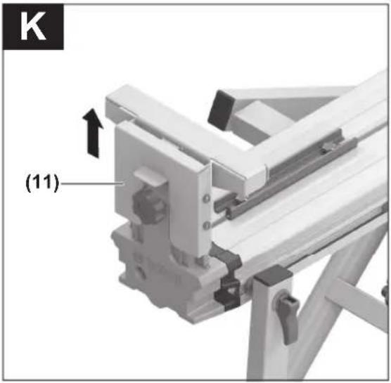
(11) Length stop
(12) Workpiece support
(13) Upper frame with locking mechanism
(14) Foot support
(15) "L" wheel
(16) "R" wheel
(17) Lower frame
(18) Support frame
(19) Fastening set
(20) Lock bolt
(21) Stop plate
(22) Hex nut
(23) Release button
(24) Holder set locking lever
(25) Stop
(26) Movable nut
(27) Nut for adjustment of the support locking mechanism
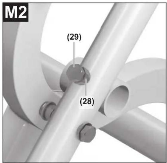
(28) Nut for adjustment of the lock bolt
(29) Screw for adjustment of the lock bolt
Technical Data
| Saw stand GTA 2500 W | |
| Article number | 3 601 M12 1.. |
| Length of saw stand without table extension | mm 1044 |
| Length of saw stand with table extension | mm 2510 |
| Saw stand height mm 947 | |
| Max. load bearing capacity (power tool + workpiece) | |
| - Holder sets kg 180 | |
| Max. load bearing capacity (power tool + workpiece) with table extension | |
| - Holder sets kg 130 | |
| - Per table extension kg 25 | |
| Weight according to EPTA-Procedure 01:2014 | kg 32.2 |
Assembly
Items included

See the list of items included at the start of the operating manual.
Check to ensure that all the parts listed below have been supplied before assembling the saw stand:
| No. Designation Quant- | ity | |
| (1) | Holder set 2 | |
| (2) | Saw stand with support (8) | 1 |
| (13) | Upper frame with locking mechanism (3) | 1 |
| (17) | Lower frame 1 | |
| (14) | Foot support 1 | |
| (15) | "L" wheel | 1 |
| (16) | "R" wheel | 1 |
| (18) | Support frame | 1 |
No. Designation Quant-
ity
| (1) | Holder set 2 | |
| (2) | Saw stand with support (8) | 1 |
| (13) | Upper frame with locking mechanism (3) | 1 |
| (17) | Lower frame 1 | |
| (14) | Foot support 1 | |
| (15) | "L" wheel | 1 |
| (16) | "R" wheel | 1 |
| (18) | Support frame | 1 |
No. Designation Quant- ity
| (19) Fastening set consisting of: | |
| - Hexagon screws | |
| M10 x 100 | 4 |
| M10 x 55 | 1 |
| M10 x 50 (self-locking) | 2 |
| M8 x 45 | 4 |
| M6 x 45 | 4 |
| - Cross-head screws | |
| M8 x 50 | 4 |
| - Washers | |
| M10 x 29 | 2 |
| M10 | 10 |
| M8 | 4 |
| M6 | 4 |
| - Lock nuts | |
| M10 | 5 |
| M8 | 4 |
| M6 | 4 |
Extra tools required (not included in the delivery):
- Cross-headed screwdriver
- Open-ended spanner (10 mm, 8 mm, 6 mm)
- Wrench, adjustable
Assembling the Mobile Base Unit
- Carefully remove all parts included in the delivery from their packaging.
- Remove all packing material.
- For assembly, follow figures A-E2.
For figure B:
For easier orientation, the wheels are marked ("R" for right-hand wheel, "L" for left-hand wheel).
Note: Do not over-tighten the nuts. The screwed-together parts must be able to move freely.
For figure D:
Ensure that the support frame (18) is installed in the correct direction, as indicated by the "R" and "L" markings that match the wheels.
Note: Do not over-tighten the nuts. The screwed-together parts must be able to move freely.
For figure E1:
In this assembly step, the saw stand (2) is screwed to the support frame (18) and the support for the upper frame (13).
- Turn both supports so that the holes in the sides of the supports point towards the handle.
- While screwing the saw stand together, ensure that the support (8) is always in the holder on the lower frame (17).
Note: Only tighten the nuts slightly at first. Once all eight screws are positioned correctly, fully tighten all the nuts.
18 | English
For figure E2:
Note: Do not over-tighten the nuts. The screwed-together parts must be able to move freely.
Preparing the Saw Stand
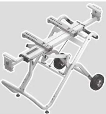
Setting up the saw stand (see figure F)
Before securing the holder set and the power tool, you must pull the base unit apart.
- To release the lock bolts (20), gently pull the saw stand upwards by the handle (6).
- Open the locking mechanism. This retracts the lock bolts which lock the wheels.
- Place one foot on the foot support (14) and push the handle (6) downwards with both hands until the lock bolts can engage again on the other side of the stop plates (21).
- Close both the locking mechanism (3) and the locking mechanism (9).
The height-adjustable feet (7) will help you to straighten the saw stand.
- Undo the hex nuts (22) and screw in/out the feet until the saw stand is level.
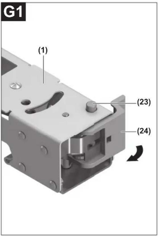
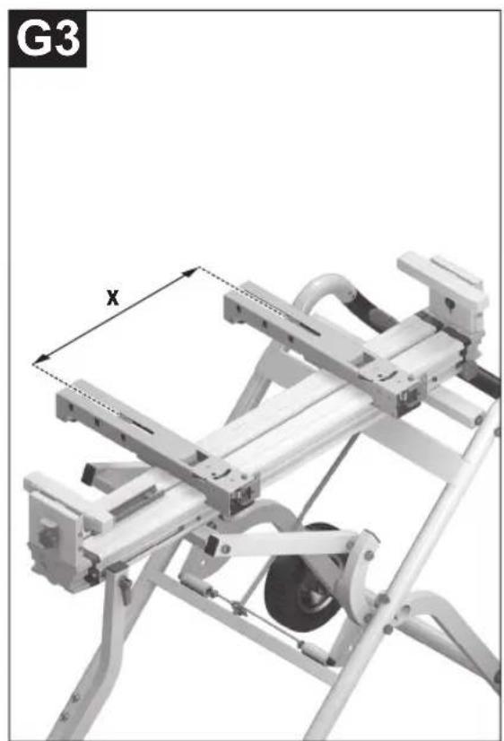
Preparing holder sets (see figures G1-G4)
- To unlock the holder set (1), press the button (23) and open the lever (24).
- Place the holder set on the saw stand (2) and push it up to the red stop (25).
- Lock the lever (24) again. This ensures that the holder set is firmly positioned on the saw stand.
- Measure the distance x between the assembly holes on your power tool.
- Unlock the second holder set and position it at a suitable distance x from the holder set that has already been positioned.
- Lock the lever (24) again.
Fastening the Power Tool on the Holder Sets (see figure H)
- Bring the power tool into the transport position. Information about the transport position can be found in the operating instructions for the corresponding power tool.
- Position the movable nuts (26) in the holder sets so that they match the assembly holes on the power tool.
- Screw together the holder set and power tool using the compatible washers and screws.
Operation
Working Advice
Before commencing work, ensure that both locking mechanisms (9) and (3) are always closed.
Always hold the workpiece firmly in place, especially long, heavy pieces. Once the workpiece has been cut, the centre of gravity may be displaced, causing the saw stand to tip over.
Do not overload the saw stand. Always observe the maximum load bearing capacity of the saw stand.
Preparing the workpiece support
The free end of long workpieces must have something placed underneath it or be supported.
Adjusting the height of the workpiece support (see figure I)
- Place your workpiece on the saw table for the power tool.
- Loosen the locking knob (10) and adjust the height of the workpiece support (12) so that your workpiece lies flat.
– Re-tighten this locking knob.
Extending the saw stand (see figure J)
The saw stand can be extended on both sides.
- Place your long workpiece on the saw table for the power tool.
- If necessary, loosen the corresponding locking knob (4) and pull the table extension (5) outwards until it reaches the required length.
- Re-tighten this locking knob.
Sawing workpieces of the same length (see figure K)
The length stop (11) can be used for easily sawing workpieces of the same length.
- Pull the length stop all the way upwards and position the workpiece support at the required distance from the power tool saw blade.
Checking and adjusting the basic settings
To ensure safe use, the basic settings of the saw stand must be checked and adjusted as necessary after intensive use. Experience and suitable special tools are required for this.
- To do so, remove the power tool with the holder sets.
Adjusting the support locking mechanism (see figure L)
The locking mechanism (9) for the support (8) can loosen over time.
- Close the locking mechanism (9).
- Push a slotted screwdriver between the saw stand and nut (27).
- Turn the locking mechanism clockwise until the lever for the locking mechanism can be firmly closed again.
- Remove the slotted screwdriver and check the adjustment again.
Adjusting the lock bolts for the wheel locking mechanism (see figures M1–M2)
Checking
- Bring the saw stand into the work position (fully pulled apart).
Both lock bolts (20) must be completely extended and there must be no gap between the lock bolts and stop plate (21).
Adjusting
- Loosen the nuts (28) (16 mm) on each side of the base unit by a quarter-turn.
- Tighten the adjusting screw (29) on the side where a gap appears between the lock bolts and stop plate. If this does not close the gap, the adjusting screw on the other side must be loosened.
- Repeat this process until both lock bolts are completely extended again and there is no gap between the lock bolts and stop plate.
- Re-tighten the nuts (28).
Transport (see figure N)
You must fold the base unit together for transport.
- Slide the table extensions (5) in fully and slide the workpiece supports (12) and length stops (11) downwards fully.
- Open the locking mechanism (9).
- To release the lock bolts (20), gently push the saw stand downwards by the handle (6).
- Open the locking mechanism (3). This retracts the lock bolts which lock the wheels.
- Place one foot on the foot support (14) and pull the handle (6) upwards with both hands until the lock bolts can engage again on the other side of the stop plates (21).
- Close the locking mechanism (3).
Maintenance and Service
After-Sales Service and Application Service
Our after-sales service responds to your questions concerning maintenance and repair of your product as well as spare parts. You can find explosion drawings and information on spare parts at: www.bosch-pt.com
The Bosch product use advice team will be happy to help you with any questions about our products and their accessories.
In all correspondence and spare parts orders, please always include the 10-digit article number given on the nameplate of the product.
Great Britain
Robert Bosch Ltd. (B.S.C.)
P.O. Box 98
Broadwater Park
North Orbital Road
Denham Uxbridge
UB 9 5HJ
At www.bosch-pt.co.uk you can order spare parts or arrange the collection of a product in need of servicing or repair.
Tel. Service: (0344) 7360109
E-Mail: boschservicecentre@bosch.com
You can find further service addresses at:
www.bosch-pt.com/serviceaddresses
Disposal
Saw stands, accessories and packaging should be recycled in an environmentally responsible manner.
Français
Robert Bosch (France) S.A.S.
www.bosch-pt.com/serviceaddresses
www.bosch-pt.com/serviceaddresses
Eliminación
www.bosch-pt.com/serviceaddresses
Eliminação
www.bosch-pt.com/serviceaddresses
Smaltimento
www.bosch-pt.com/serviceaddresses
Afvalverwijdering
Bosch Service Center
Telegrafvej 3
2750 Ballerup
På www.bosch-pt.dk kan der online bestilles reservedele eller oprettes en reparations ordre.
Tlf. Service Center: 44898855
Fax: 44898755
E-Mail: vaerktoej@dk.bosch.com
www.bosch-pt.com/serviceaddresses
Bortskaffelse
Bosch Service Center
Telegrafvej 3
2750 Ballerup
Danmark
Tel.: (08) 7501820 (inom Sverige)
Fax: (011) 187691
www.bosch-pt.com/serviceaddresses
Avfallshantering
www.bosch-pt.com/serviceaddresses
Deponering
www.bosch-pt.com/serviceaddresses
Hävitys
www.bosch-pt.com/serviceaddresses
Απόσυρση
www.bosch-pt.com/serviceaddresses
Tasfiye
Robert Bosch Sp. z o.o.
www.bosch-pt.com/serviceaddresses
Utylizacja odpadów
Bosch Service Center PT
K Vápence 1621/16
692 01 Mikulov
www.bosch-pt.com/serviceaddresses
Likvidace
www.bosch-pt.com/serviceaddresses
Likvidácia
www.bosch-pt.com/serviceaddresses
Eltávolítás
www.bosch-pt.com/serviceaddresses
Утилизация
www.bosch-pt.com/serviceaddresses
Кәдеге жарату
Service scule electrice
Strada Horia Măcelariu Nr. 30–34, sector 1
013937 Bucureşti
www.bosch-pt.com/serviceaddresses
Eliminare
Service scule electrice
Strada Horia Măcelariu Nr. 30-34, sector 1
013937 Bucureşti, România
www.bosch-pt.com/bg/bg/
www.bosch-pt.com/serviceaddresses
Бракуване
www.bosch-pt.com/serviceaddresses
Отстранување
www.bosch-pt.com/serviceaddresses
Uklanjanje dubreta
www.bosch-pt.com/serviceaddresses
Odlaganje
Delovne mize, pribor in embalažo oddajte v okolju prijazno recikliranje.
Hrvatski
Sigurnosne napomene
www.bosch-pt.com/serviceaddresses
Zbrinjavanje
www.bosch-pt.com/serviceaddresses
www.bosch-pt.com/serviceaddresses
www.bosch-pt.com/serviceaddresses
Šalinimas
www.bosch-pt.com/serviceaddresses
처리
Robert Bosch Morocco SARL
www.bosch-pt.com/serviceaddresses

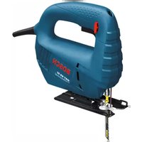

- GTA 2500 W Professional
- Deutsch
- Sicherheitshinweise
- Entsorgung
- General Safety Instructions
- Safety Instructions for Saw Stands
- | English
- Symbols
- Symbols and their meaning
- Product description and specifications
- Intended Use
- Product Features
- Assembly
- Items included
- Extra tools required (not included in the delivery):
- Assembling the Mobile Base Unit
- For figure B:
- For figure D:
- For figure E1:
- | English
- For figure E2:
- Preparing the Saw Stand
- Setting up the saw stand (see figure F)
- Preparing holder sets (see figures G1-G4)
- Fastening the Power Tool on the Holder Sets (see figure H)
- Operation
- Working Advice
- Preparing the workpiece support
- Adjusting the height of the workpiece support (see figure I)
- Extending the saw stand (see figure J)
- Sawing workpieces of the same length (see figure K)
- Checking and adjusting the basic settings
- Adjusting the support locking mechanism (see figure L)
- Adjusting the lock bolts for the wheel locking mechanism (see figures M1–M2)
- Checking
- Adjusting
- Transport (see figure N)
- Maintenance and Service
- After-Sales Service and Application Service
- Great Britain
- You can find further service addresses at:
- Disposal
- Français
- Eliminación
- Eliminação
- Smaltimento
- Afvalverwijdering
- Bortskaffelse
- Avfallshantering
- Deponering
- Hävitys
- Απόσυρση
- Tasfiye
- Utylizacja odpadów
- Likvidace
- Likvidácia
- Eltávolítás
- Утилизация
- Кәдеге жарату
- Eliminare
- Бракуване
- Отстранување
- Uklanjanje dubreta
- Odlaganje
- Hrvatski
- Sigurnosne napomene
- Zbrinjavanje
- Šalinimas
- 처리
Brand : BOSCH
Model : GTA 2500 W Professional
Category : Saw