
PCM 8 SD - Saw BOSCH - Free user manual and instructions
Find the device manual for free PCM 8 SD BOSCH in PDF.


| Product type | Sliding compound miter saw |
| Brand | Bosch |
| Model | PCM 8 SD |
| Dimensions (L × W × H) | 660 × 500 × 460 mm |
| Weight | 15.5 kg |
| Power supply | 230 V ~ 50 Hz |
| Power input | 1600 W |
| Blade diameter | 210 mm |
| No-load speed | 5000 rpm |
| Cutting depth at 90° | 70 mm |
| Cutting depth at 45° | 50 mm |
| Miter range left/right | 0-45° / 0-45° |
| Bevel range left | 0-45° |
| Main functions | Miter, bevel, compound, and sliding cuts; depth stop; laser guide; precision guide |
| Maintenance and cleaning | Clean slides regularly, replace worn brushes, blow out sawdust |
| Safety | Electric blade brake, safety switch, protective guard |
| Spare parts and repairability | Blades, dust bag, carbon brushes, power cable available |
| General information | 2-year warranty, made in China |
Frequently Asked Questions - PCM 8 SD BOSCH
User questions about PCM 8 SD BOSCH
0 question about this device. Answer the ones you know or ask your own.
Ask a new question about this device
Download the instructions for your Saw in PDF format for free! Find your manual PCM 8 SD - BOSCH and take your electronic device back in hand. On this page are published all the documents necessary for the use of your device. PCM 8 SD by BOSCH.
USER MANUAL PCM 8 SD BOSCH
Robert Bosch Power Tools GmbH
70538 Stuttgart
GERMANY
www.bosch-pt.com
1609 92A 3VU (2017.07) PS / 306
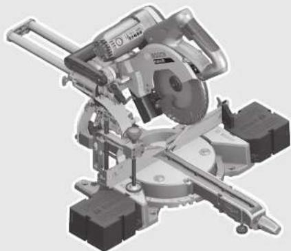
PCM
8 SD|800 SD

BOSCH




10

12

Deutsch | 13
Deutsch
Safety Instructions
General Power Tool Safety Warnings
WARNING: Read all safety warnings, instructions, illustrations and specifications provided
with this power tool. Failure to follow all instructions listed below may result in electric shock, fire and/or serious injury.
Save all warnings and instructions for future reference.
The term "power tool" in the warnings refers to your mains-operated (corded) power tool or battery-operated (cordless) power tool.
Work area safety
- Keep work area clean and well lit. Cluttered or dark areas invite accidents. Do not operate power tools in explosive atmospheres, such as in the presence of flammable liquids, gases or dust. Power tools create sparks which may ignite the dust or fumes. Keep children and bystanders away while operating a power tool. Distractions can cause you to lose control.
Electrical safety
Power tool plugs must match the outlet. Never modify the plug in any way. Do not use any adapter plugs with earthed (grounded) power tools. Unmodified plugs and matching outlets will reduce risk of electric shock. Avoid body contact with earthed or grounded surfaces, such as pipes, radiators, ranges and refrigerators. There is an increased risk of electric shock if your body is earthed or grounded. Do not expose power tools to rain or wet conditions. Water entering a power tool will increase the risk of electric shock. Do not abuse the cord. Never use the cord for carrying, pulling or unplugging the power tool. Keep cord away from heat, oil, sharp edges and moving parts. Damaged or entangled cords increase the risk of electric shock. When operating a power tool outdoors, use an extension cord suitable for outdoor use. Use of a cord suitable for outdoor use reduces the risk of electric shock. If operating a power tool in a damp location is unavoidable, use a residual current device (RCD) protected supply. Use of an RCD reduces the risk of electric shock.
Personal safety
Stay alert, watch what you are doing and use common sense when operating a power tool. Do not use a power tool while you are tired or under the influence of drugs, alcohol or medication. A moment of inattention while operating power tools may result in serious personal injury. Use personal protective equipment. Always wear eye protection. Protective equipment such as dust mask, non-skid safety shoes, hard hat, or hearing protection
used for appropriate conditions will reduce personal injuries.
Prevent unintentional starting. Ensure the switch is in the off-position before connecting to a power source and/or battery pack, picking up or carrying the tool. Carrying power tools with your finger on the switch or energizing power tools that have the switch on invites accidents. Remove any adjusting key or wrench before turning the power tool on. A wrench or a key left attached to a rotating part of the power tool may result in personal injury. Do not overreach. Keep proper footing and balance at all times. This enables better control of the power tool in unexpected situations. Dress properly. Do not wear loose clothing or jewelry. Keep your hair and clothing away from moving parts. Loose clothes, jewelry, or long hair can be caught in moving parts. If devices are provided for the connection of dust extraction and collection facilities, ensure these are connected and properly used. Use of dust collection can reduce dust-related hazards. Do not let familiarity gained from frequent use of tools allow you to become complacent and ignore tool safety principles. A careless action can cause severe injury within a fraction of a second. Do not force the power tool. Use the correct power tool for your application. The correct power tool will do the job better and safer at the rate for which it was designed. Do not use the power tool if the switch does not turn it on and off. Any power tool that cannot be controlled with the switch is dangerous and must be repaired. Disconnect the plug from the power source and/or remove the battery pack, if detachable, from the power tool before making any adjustments, changing accessories, or storing power tools. Such preventive safety measures reduce the risk of starting the power tool accidentally. Store idle power tools out of the reach of children and do not allow persons unfamiliar with the power tool or these instructions to operate the power tool. Power tools are dangerous in the hands of untrained users. Maintain power tools and accessories. Check for misalignment or binding of moving parts, breakage of parts and any other condition that may affect the power tool's operation. If damaged, have the power tool repaired before use. Many accidents are caused by poorly maintained power tools. Keep cutting tools sharp and clean. Properly maintained cutting tools with sharp cutting edges are less likely to bind and are easier to control. Use the power tool, accessories and tool bits etc. in accordance with these instructions, taking into account the working conditions and the work to be performed.
Power tool use and care
24 | English
Use of the power tool for operations different from those intended could result in a hazardous situation.
Keep handles and grasping surfaces dry, clean and free from oil and grease. Slippery handles and grasping surfaces do not allow for safe handling and control of the tool in unexpected situations.
Service
Have your power tool serviced by a qualified repair person using only identical replacement parts. This will ensure that the safety of the power tool is maintained.
Safety Warnings for Mitre Saws
- Mitre saws are intended to cut wood or wood-like products; they cannot be used with abrasive cut-off wheels for cutting ferrous material such as bars, rods, studs, etc. Abrasive dust causes moving parts such as the lower guard to jam. Sparks from abrasive cutting will burn the lower guard, the kerf insert, and other plastic parts. Use clamps to support the workpiece whenever possible. If supporting the workpiece by hand, you must always keep your hand at least 100 mm from either side of the saw blade. Do not use this saw to cut pieces that are too small to be securely clamped or held by hand. If your hand is placed too close to the saw blade, there is an increased risk of injury from blade contact. The workpiece must be stationary and clamped or held against both the fence and the table. Do not feed the workpiece into the blade or cut "freehand" in any way. Unrestrained or moving workpieces could be thrown at high speeds, causing injury. Push the saw through the workpiece. Do not pull the saw through the workpiece. To make a cut, raise the saw head and pull it out over the workpiece without cutting, start the motor, press the saw head down, and push the saw through the workpiece. Cutting on the pull stroke is likely to cause the saw blade to climb on top of the workpiece and violently throw the blade assembly towards the operator. Never cross your hand over the intended line of cutting either in front or behind the saw blade. Supporting the workpiece "cross handed" i.e., holding the workpiece to the right of the saw blade with your left hand or vice versa is very dangerous. Do not reach behind the fence with either hand closer than 100 mm from either side of the saw blade, to remove wood scraps, or for any other reason while the blade is spinning. The proximity of the spinning saw blade to your hand may not be obvious and you may be seriously injured. Inspect your workpiece before cutting. If the workpiece is bowed or warped, clamp it with the outside bowed face toward the fence. Always make certain that there is no gap between the workpiece, fence, and table along the line of the cut. Bent or warped workpieces can twist or shift and may cause binding on the spinning saw blade while cutting. There should be no nails or foreign objects in the workpiece.
Do not use the saw until the table is clear of all tools, wood scraps, etc., except for the workpiece. Small debris or loose pieces of wood or other objects that contact the revolving blade can be thrown with high speed. ▶ Cut only one workpiece at a time. Stacked multiple workpieces cannot be adequately clamped or braced and may bind on the blade or shift during cutting. ▶ Ensure the mitre saw is mounted or placed on a level, firm work surface before use. A level and firm work surface reduces the risk of the mitre saw becoming unstable. ▶ Plan your work. Every time you change the bevel or mitre angle setting, make sure the adjustable fence is set correctly to support the workpiece and will not interfere with the blade or the guarding system. Without turning the tool "ON" and with no workpiece on the table, move the saw blade through a complete simulated cut to assure there will be no interference or danger of cutting the fence. ▶ Provide adequate support such as table extensions, saw horses, etc. for a workpiece that is wider or longer than the table top. Workpieces longer or wider than the mitre saw table can tip if not securely supported. If the cut-off piece or workpiece tips, it can lift the lower guard or be thrown by the spinning blade. Do not use another person as a substitute for a table extension or as additional support. Unstable support for the workpiece can cause the blade to bind or the workpiece to shift during the cutting operation pulling you and the helper into the spinning blade. The cut-off piece must not be jammed or pressed by any means against the spinning saw blade. If confined, i.e. using length stops, the cut-off piece could get wedged against the blade and thrown violently. ▶ Always use a clamp or a fixture designed to properly support round material such as rods or tubing. Rods have a tendency to roll while being cut, causing the blade to "bite" and pull the work with your hand into the blade. ▶ Let the blade reach full speed before contacting the workpiece. This will reduce the risk of the workpiece being thrown. If the workpiece or blade becomes jammed, turn the mitre saw off. Wait for all moving parts to stop and disconnect the plug from the power source and/or remove the battery pack. Then work to free the jammed material. Continued sawing with a jammed workpiece could cause loss of control or damage to the mitre saw. ▶ After finishing the cut, release the switch, hold the saw head down and wait for the blade to stop before removing the cut-off piece. Reaching with your hand near the coasting blade is dangerous. The power tool is provided with a laser warning label (marked with number 3 in the representation of the power tool on the graphics page).

If the text of the warning label is not in your national language, stick the provided warning label in your national language over it before operating for the first time.
Do not direct the laser beam at persons or animals and do not stare into the direct or reflected laser beam yourself, not even from a distance. You could blind somebody, cause accidents or damage your eyes.
▶ If laser radiation strikes your eye, you must deliberately close your eyes and immediately turn your head away from the beam. ▶ Do not make any modifications to the laser equipment. ▶ Never make warning signs on the machine unrecognisable. ▶ Do not use dull, cracked, bent or damaged saw blades. Unsharpened or improperly set saw blades produce narrow kerf causing excessive friction, blade binding and kick-back. ▶ Do not use high speed steel (HSS) saw blades. Such saw blades can easily break. ▶ Always use blades with correct size and shape (diamond versus round) of arbour holes. Blades that do not match the mounting hardware of the saw will run eccentrically, causing loss of control. ▶ Do not touch the saw blade after working before it has cooled. The saw blade becomes very hot while working.
Products sold in GB only: Your product is fitted with a BS 1363/A approved electric plug with internal fuse (ASTA approved to BS 1362).
If the plug is not suitable for your socket outlets, it should be cut off and an appropriate plug fitted in its place by an authorised customer service agent. The replacement plug should have the same fuse rating as the original plug.
The severed plug must be disposed of to avoid a possible shock hazard and should never be inserted into a mains socket elsewhere.
Symbols
The following symbols can be important for the operation of your power tool. Please memorise the symbols and their meanings. The correct interpretation of the symbols helps you operate the power tool better and more safely.
Symbols and their meaning

▶ Keep hands away from the cutting area while the machine is running. Danger of injury when coming in contact with the saw blade.

▶ Wear a dust respirator.
Symbols and their meaning
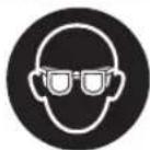
▶ Wear safety goggles.

▶ Wear ear protectors. Exposure to noise can cause hearing loss.
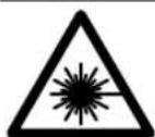
▶ Laser Radiation Do not stare into beam Class 2 laser product

▶ Danger area! Keep hands, fingers or arms away from this area.
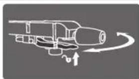
To set horizontal mitre angles, turn the saw table with the lever pulled until the angle indicator shows the required mitre angle.

The adjustable fence must be pulled outward when sawing bevel angles.

Observe the dimensions of the saw blade. The hole diameter must match the tool spindle without play. If reducers are necessary, ensure that their dimensions are suitable for the base blade thickness, the saw blade hole diameter, and the tool spindle diameter. Wherever possible, use the reducers provided with the saw blade.

The cutting line can be indicated by the laser beam on either the left or right of the saw blade.
Product Description and Specifications

Read all safety warnings and all instructions. Failure to follow the warnings and instructions may result in electric shock, fire, and/or serious injury.
Intended Use
The power tool is intended as a stationary machine for making straight lengthways and crossways cuts in wood. In this, horizontal mitre angles from -48° to +48° as well as vertical bevel angles from 45° (leftward) to 45° (rightward) are possible. The capacity of the power tool is designed for sawing hardwood and softwood, as well as particle and fibre board.
The power tool is not suitable for cutting aluminium or other non-ferrous metals or alloys.
Product Features
The numbering of the components shown refers to the representation of the power tool on the graphic pages.
1 Slide device 2 Transport handle 3 Laser warning label 4 Lock-off button for On/Off switch 5 On/Off switch 6 Handle 7 Blade guard 8 Retracting blade guard 9 Adjustable fence
10 Material stop
11 Fixed fence
12 Saw-table extension (stationary)
13 Locking knob for various mitre angles
25 Locking screw for slide device
26 On/Off switch for laser (cutting line indication)
27 Chip ejector
28 Transport safety-lock
29 Tilt-protector bar
30 Bevel lock lever
31 Holes for quick-action clamp
32 Spindle lock
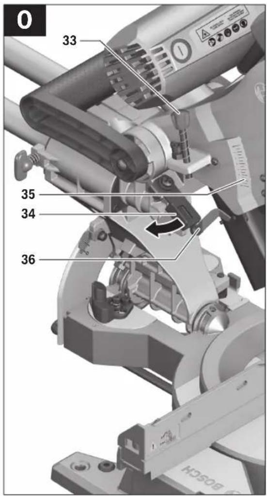
33 Adjusting screw of depth stop 34 Depth stop 35 Cutting-depth scale 36 Cutting-depth indicator 37 Sliding switch for laser (cutting line indication on left/right of saw blade) 38 Laser beam outlet 39 Right bevel angle indicator 40 Scale for bevel angle 41 Stop screw for left-hand bevel angle range 42 Stop for standard bevel angles 45°, 22.5° and 33.9° (left) 43 Left bevel angle indicator 44 Stop screw for right-hand bevel angle range 45 Stop for standard bevel angle 45° (right) 46 Stop screw for 0° bevel angle 47 Stop for 0° standard bevel angle 48 Clamping lever of the adjustable fence 49 Hex key 50 Clamping lever of the material stop 51 Fastening screw for stationary saw-table extension 12 52 Opening for stationary saw-table extension 12 53 Dust bag 54 Hex socket screw for mounting of saw blade 55 Clamping flange 56 Saw blade 57 Interior clamping flange 58 Quick release of quick-action clamp 59 Locking knob of the quick-action clamp 60 Wing bolt of the quick-action clamp 61 Supporting bar of the quick-action clamp 62 Mounting holes for horizontal fixing 63 Saw-table extension (flexible) 64 Opening for flexible saw-table extension 63 (on the power tool) 65 Opening for flexible saw-table extension 63 (on the stationary saw-table extension 12) 66 Fastening screw for insert plate Accessories shown or described are not part of the standard delivery scope of the product. A complete overview of accessories can be found in our accessories program.
Noise Information
Sound emission values determined according to EN 62841-3-9.
Typically the A-weighted noise levels of the product are: Sound pressure level 93 dB(A); Sound power level 106 dB(A). Uncertainty K = 3 dB.
Wear hearing protection!
English | 27
Technical Data
| Sliding Mitre Saw PCM 8 SD | PCM 800 SD | |
| Article number | 3603M110 | |
| Rated power input | W 1200 | |
| No-load speed | min 1 | 4800 |
| Laser type | nm | 650 |
| mW | < 1 | |
| Laser class | 2 | |
| Divergence of laser line | mrad(full angle) 1.0 | |
| Weight according to EPTA-Procedure 01:2014 | kg 15.5 | |
| Protection class | ☐/II | |
Permissible workpiece dimensions (maximum/minimum) see page 30. The values given are valid for a nominal voltage [U] of 230 V. For different voltages and models for specific countries, these values can vary.
Dimension of suitable saw blades
| Saw blade diameter | mm 216 | |
| Blade body thickness | mm 1.4-1.8 | |
| Max. cutting width | mm | 2 |
| Mounting hole diameter | mm | 30 |
Assembly
- Avoid unintentional starting of the machine. During assembly and for all work on the machine, the power plug must not be connected to the mains supply.
Delivery Scope

Please also observe the representation of the delivery scope at the beginning of the operating instructions.
Before starting the operation of the machine for the first time, check if all parts listed below have been supplied:
- Sliding mitre saw with mounted saw blade
- Dust bag 53
- Stationary saw-table extension 12 (2 x), Fastening screws 51 (2 x)
- flexible saw-table extension 63 (2 x)
- Quick-action clamp 22
- H e x k e y 49
Note: Check the power tool for possible damage.
Before further use of the machine, check that all protective devices are fully functional. Any lightly damaged parts must be carefully checked to ensure flawless operation of the tool. All parts must be properly mounted and all conditions fulfilled that ensure faultless operation.
Damaged protective devices and parts must be immediately replaced by an authorised service centre.
Mounting Individual Components
- Carefully remove all parts included in the delivery from their packaging.
- Remove all packaging material from the machine and the accessories provided.
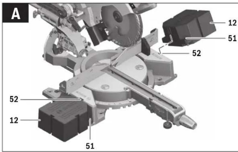
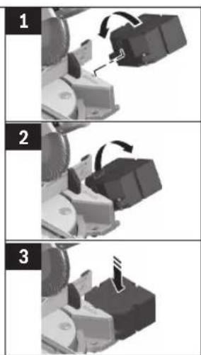
Mounting stationary saw-table extensions (see figure A)
The stationary saw-table extensions 12 with the fastening screws 51 must be screwed to the left and right of the saw table 21 with the power tool.
- Tilt the saw-table extension 12 backward slightly and place it in the groove of the opening 52 on the power tool, turn the saw-table extension forward horizontally in the groove and then press the saw-table extension fully downward.
- Tighten the fastening screws 51 with the hex key 49 provided.
Stationary or Flexible Mounting
To ensure safe handling, the machine must be mounted on a level and stable surface (e.g., workbench) prior to using.
Mounting to a Working Surface (see figure B)
- Fasten the power tool with suitable screw fasteners to the working surface. The mounting holes 20 serve for this purpose.
Flexible Mounting (not recommended!) (see figure C)
In exceptional cases, when it is not possible to mount the machine onto a level and stable work surface, it can be set up using the tilt protector.
▶ Without the use of the tilt protector, the machine does not stand safely and can tip over, especially when sawing at maximum mitre/bevel angles. - Screw the tilt protector 15 in or out until the machine is positioned level on the working surface.
Dust/Chip Extraction
Dust from materials such as lead-containing coatings, some wood types, minerals and metal can be harmful to one's health. Touching or breathing-in the dust can cause allergic reactions and/or lead to respiratory infections of the user or bystanders.
Certain dust, such as oak or beech dust, is considered carcinogenic, especially in connection with wood-treatment additives (chromate, wood preservative). Materials containing asbestos may only be worked by specialists.
- Always use dust extraction.
- Provide for good ventilation of the working place.
- It is recommended to wear a P2 filter-class respirator.
Observe the relevant regulations in your country for the materials to be worked.
The dust/chip extraction can be blocked by dust, chips or workpiece fragments.
- Switch the machine off and pull the mains plug from the socket outlet.
- Wait until the saw blade has come to a complete stop.
- Determine the cause of the blockage and correct it.
Integrated Dust Extraction (see figure D)
- Mount the dust bag 53 onto the chip ejector 27.
28 | English
During sawing, the dust bag must never come into contact with the movable machine parts.
Always empty the dust bag in good time.
External Dust Extraction
For dust extraction, a vacuum hose (size ∅ 35 mm) can also be connected to the chip ejector 27.
The vacuum cleaner must be suitable for the material being worked.
When vacuuming dry dust that is especially detrimental to health or carcinogenic, use a special vacuum cleaner.
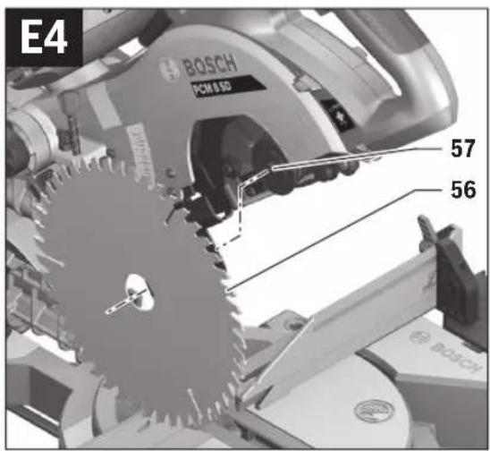
Changing the Tool (see figures E1–E4)
▶ Before any work on the machine itself, pull the mains plug. ▶ When mounting the saw blade, wear protective gloves.
Danger of injury when touching the saw blade.
Use only saw blades whose maximum permitted speed is higher than the no-load speed of the power tool.
Use only saw blades that correspond with the characteristic data given in these operation instructions and that are tested and marked in accordance with EN 847-1.
Use only saw blades recommended by the tool manufacturer, and suitable for sawing the materials to be cut. This prevents overheating of the saw teeth during sawing.
Removing the Saw Blade
- Bring the power tool into the working position.
- Turn the hex socket screw 54 with the provided hex key 49 while simultaneously pressing the spindle lock 32 until it engages.
- Hold the spindle lock 32 pressed and turn the hex socket screw 54 in the clockwise direction (left-hand thread!).
- Remove the clamping flange 55.
- Swing the retracting blade guard 8 backward and remove the saw blade 56.
- Slowly guide the retracting blade guard downward again.
Mounting the Saw Blade
If required, clean all parts to be mounted prior to assembly. - Swing the retracting blade guard 8 backward. - Place the new saw blade onto the interior clamping flange 57. When mounting the saw blade, pay attention that the cutting direction of the teeth (arrow direction on the saw blade) corresponds with the direction of the arrow on the blade guard! - Slowly guide the retracting blade guard downward again. - Place on the clamping flange 55 and the screw 54. Press the spindle lock 32 until it engages and tighten the screw turning in the anticlockwise direction. When attaching the clamping flange, ensure that the wide side faces the saw blade (see figure E2). The saw blade cannot be tightened if it is installed the other way round.
Operation
▶ Before any work on the machine itself, pull the mains plug.
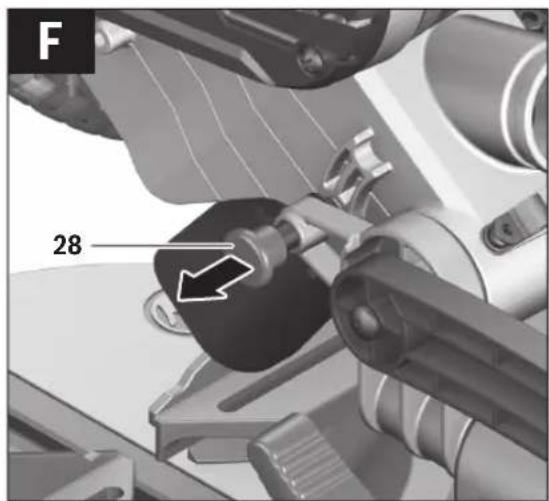
Transport Safety (see figure F)
The transport safety-lock 28 enables easier handling of the machine when transporting to various working locations.
Releasing the Machine (Working Position)
- Push the tool arm by the handle 6 down a little in order to relieve the transport safety-lock 28.
- Pull the transport safety-lock 28 completely outward.
- Guide the tool arm slowly upward.
Securing the Machine (Transport Position)
- Loosen the locking screw 25 if it is locking the slide device 1. Pull the tool arm fully forward and tighten the locking screw again to lock the slide device.
- Screw adjusting screw 33 completely upward.
- To lock the saw table 21, tighten the locking knob 13.
- Swing the tool arm downward by the handle 6 until you can press the transport safety-lock 28 completely inward.
The tool arm is now securely locked for transport.
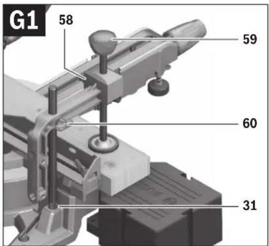
Clamping the Workpiece (see figures G1-G3)
Vertical Clamping
- Insert the quick-action clamp 22 provided into one of the holes 31 intended for this purpose.
- Press the workpiece firmly against the fences 9 and 11.
- Press the quick-release button 58 and adapt the quick-action clamp to the workpiece.
Afterward, turn the locking knob 59 in clockwise direction to clamp the workpiece.
Horizontal Clamping
- Unscrew the wing bolt 60 and pull the quick-action clamp off the supporting bar 61.
- Insert the now "reduced" quick-action clamp 22 into one of the mounting holes 62 provided (see figure G2 for fixing beams, see figure G3 for fixing skirting boards). Use the wing bolt 60 to clamp the quick-action clamp back onto the supporting bar 61.
- Press the workpiece firmly against the saw table 21.
- Press the quick-release button 58 and adapt the quick-action clamp to the workpiece.
- Afterwards, turn the locking knob 59 in clockwise direction to clamp the workpiece.
Loosening the Workpiece
- To release the quick-action clamp, firstly turn the loosening knob 59 in anticlockwise direction.
- Now press on the quick-release button 58 and pull the threaded rod away from the workpiece.
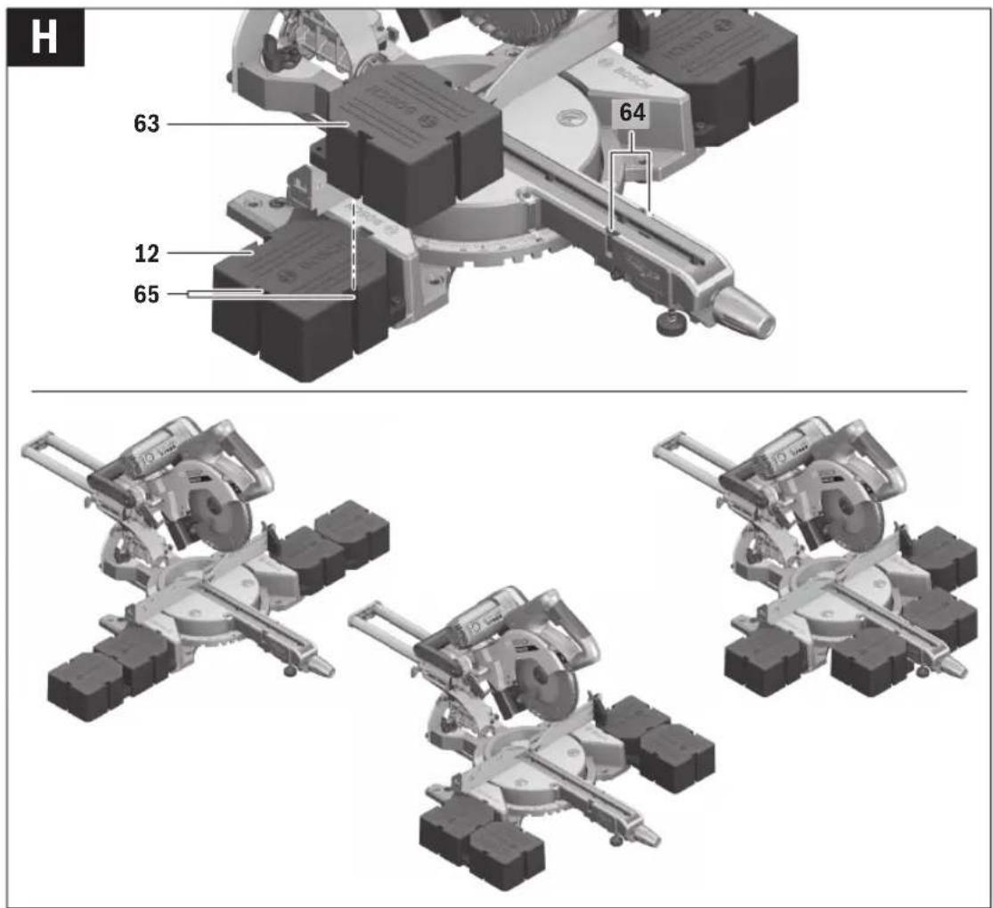
Extending the Saw Table (see figure H)
Long workpieces must be underlaid or supported at their free end.
The flexible insertion system of the saw-table extensions 63 provides you with a wide variety of extension alternatives.
- Insert as required the two flexible saw-table extensions 63 into the openings 64 on the power tool or into the openings 65 of the mounted saw-table extensions.
Compound mitre cuts
Note: When making cuts with combined horizontal mitre and vertical bevel angles, always set the vertical bevel angle first and then the horizontal mitre angle.
Adjusting Mitre Angles (see figure I)
The mitre angle can be set in the range from 48° (left side) to 48° (right side).
- Loosen the locking knob 13 in case it is tightened.
- Pull the lever 14 and turn the saw table 21 until the desired mitre angle is indicated on the angle indicator 17.
- Tighten the locking knob 13 again.
For quick and precise setting of often used mitre angles, the saw table 21 engages at the detents of the following standard angles:
Left Right
0°
45° 30° 22.5° 15° 15° 22.5° 30° 45°
Adjusting Bevel Angles
The vertical bevel angle can be adjusted in a range from 45° (leftward) to 45° (rightward).
For quick and precise setting of frequently used bevel angles, stops have been provided for the angles 0° and 45°, and additionally on the left-hand side for the angles 33.9° and 22.5°.
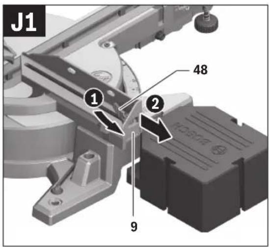
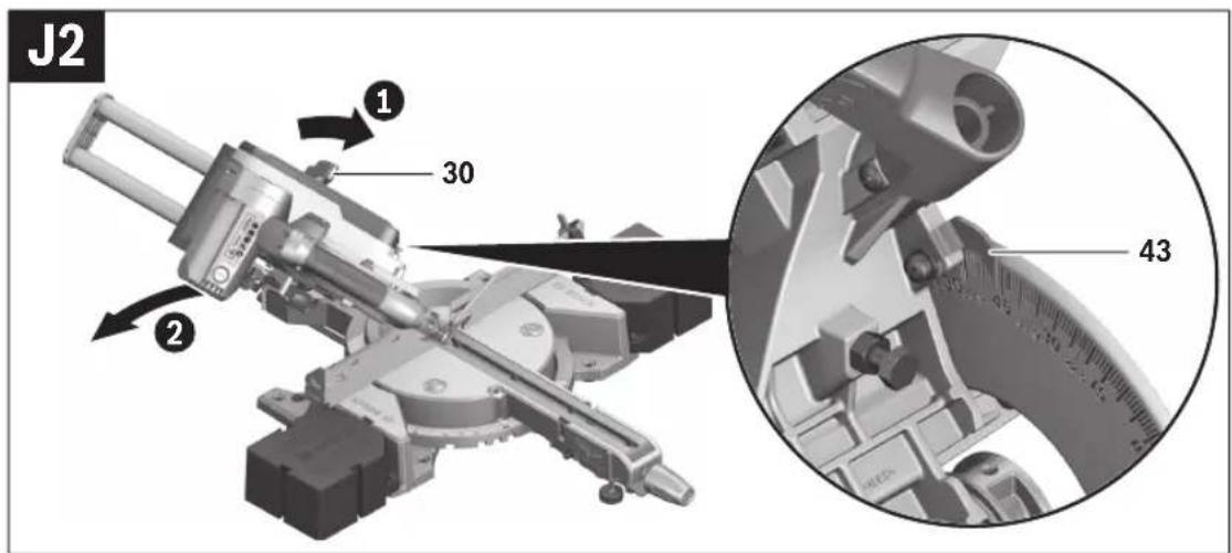
Adjusting the Left-hand Bevel Angle Range (see figures J1-J2)
- Loosen the clamping lever 48 and pull the left-hand adjustable fence 9 completely outward. Retighten the clamping lever 48.
- Loosen the lock lever 30.
- Tilt the tool arm leftward via handle 6 until the angle indicator 43 indicates the desired bevel angle.
- Retighten the lock lever 30 again.
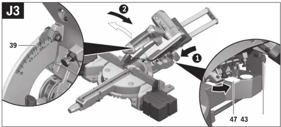
Adjusting the Complete Bevel Angle Range (see figure J3)
- Swing the stop 47 completely outward. This enables you to use the complete bevel angle range (left and right).
- Loosen the clamping lever 48 and pull the right-hand adjustable fence 9 completely outward. Retighten the clamping lever 48. If you want to use the complete bevel angle range, you also have to pull the left-hand adjustable fence 9 completely outward.
- Loosen the lock lever 30.
- Tilt the tool arm via handle 6 to the left or right until angle indicator 43 or 39 indicate the desired bevel angle.
- Retighten the lock lever 30 again.
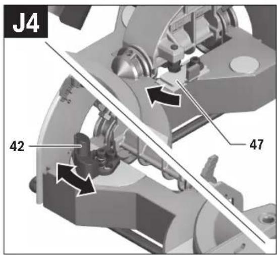
Adjusting Standard Bevel Angles (see figure J4)
- Loosen the lock lever 30.
- Standard 0° Bevel Angle: Swing the tool arm by the handle 6 slightly to the left and swing the stop 47 completely inward. Standard bevel angles 45°, 33.9° and 22.5°: Turn the stop 42 until the required standard bevel angle engages at the arrow mark.
- Retighten the lock lever 30 again.
Starting Operation
▶ Observe correct mains voltage! The voltage of the power source must agree with the voltage specified on the nameplate of the machine. Power tools marked with 230 V can also be operated with 220 V.
Products sold in AUS and NZ only: Use a residual current device (RCD) with a rated residual current of 30 mA or less.
Switching On (see figure K)
To save energy, only switch the power tool on when using it.
- To switch on the power tool, first press the lock-off button 4 right or left. Then press the On/Off switch 5 and keep it pressed.
Note: For safety reasons, the On/Off switch 5 cannot be locked; it must remain pressed during the entire operation.
Switching Off
- To switch off the machine, release the On/Off switch 5.
Working Advice
General Sawing Instructions
▶ Always firmly tighten locking knob 13 and lock lever 30 before sawing. Otherwise the saw blade could become jammed in the workpiece.
Make sure that the retracting blade guard operates properly and that it can move freely. The retracting blade guard must open when the tool arm is guided downward. The retracting blade guard must close again completely over the saw blade when the tool arm is guided upward.
Only saw materials which are permitted within the scope of the intended use.
Protect the saw blade against impact and shock. Do not subject the saw blade to lateral pressure.
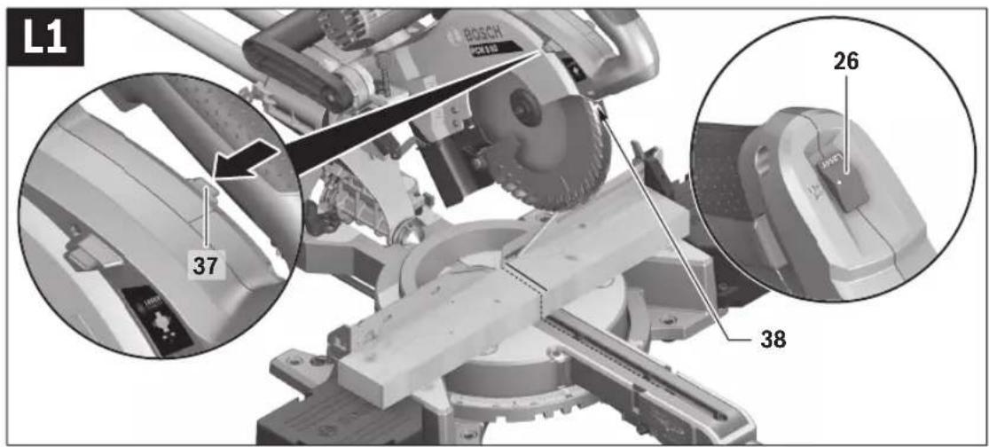
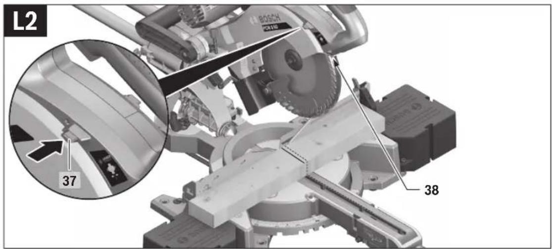
Marking the Cutting Line (see figures L1-L2)
A laser beam indicates the cutting line of the saw blade. This allows for exact positioning of the workpiece for sawing, without having to open the retracting blade guard.
- For this, switch the laser beam on with the switch 26.
- Slide the laser beam using the sliding switch 37 to the left or right depending on the preferred viewing direction. As a result, the cutting line will be indicated on either the left or right of the saw blade.
- If the cutting line is indicated by the laser beam on the left of the saw blade, align your mark on the workpiece with the right-hand edge of the laser line. If the cutting line is indicated by the laser beam on the right of the saw blade, align your mark on the workpiece with the left-hand edge of the laser line.
30 | English
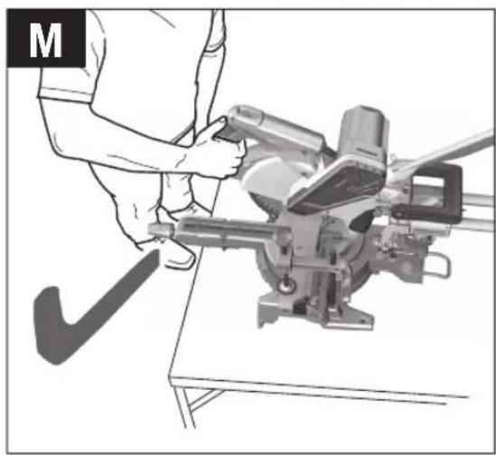
Position of the Operator (see figure M)
Do not stand in line with the saw blade in front of the machine. Always stand aside of the saw blade. This protects your body against possible kickback.
Permissible Workpiece Dimensions
Maximum workpiece sizes:
| Mitre/Bevel Angle Height x WidthHorizontal Vertical | |
| 0° 0° | 70 x 305 mm |
| 45° 0° | 70 x 215 mm |
| 0° 45° | 40 x 305 mm |
| 45° 45° | 40 x 215 mm |
Minimum workpiece sizes (= all workpieces that can be clamped left or right from the saw blade with the provided quick-action clamp 22):
100 x 40 mm (length x width)
Cutting depth, max. (0°/0°): 70 mm
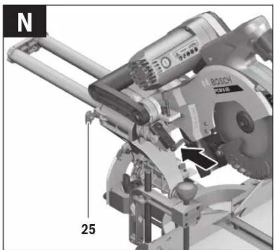
Sawing without Slide Movement (Cutting Off) (see figure N)
- For cuts without slide movement (small workpieces), loosen the locking screw 25 if it is tightened. Push the tool arm all the way towards the fences 9 and 11 and retighten the locking screw 25.
- Set the required mitre angle as necessary. For all cuts, it must first be ensured that the saw blade at no time can come in contact with the fence, screw clamps or other machine parts. Remove any mounted auxiliary stops or adjust them accordingly.
- Firmly clamp the workpiece as appropriate for its dimensions.
- Switch on the machine.
- Slowly guide the tool arm downward with the handle 6.
- Saw through the workpiece applying uniform feed.
- Switch off the machine and wait until the saw blade has come to a complete stop.
- Guide the tool arm slowly upward.
Sawing with Slide Movement
- For cuts using the slide device 1 (wide workpieces), loosen the locking screw 25 in case it is tightened.
- Set the required mitre angle as necessary. For all cuts, it must first be ensured that the saw blade at no time can come in contact with the fence, screw clamps or other machine parts. Remove any mounted auxiliary stops or adjust them accordingly.
- Firmly clamp the workpiece as appropriate for its dimensions.
- Pull the tool arm away from the fences 9 and 11 until the saw blade is in front of the workpiece.
- Switch on the machine.
- Slowly guide the tool arm downward with the handle 6.
- Now push the tool arm toward the fences 9 and 11 and saw through the workpiece with uniform feed.
- Switch off the machine and wait until the saw blade has come to a complete stop.
- Guide the tool arm slowly upward.
Adjusting the Depth Stop (Sawing Grooves) (see figure O)
The depth stop must be adjusted when a trench gap is to be sawed.
- Swivel the depth stop 34 outward.
- Swing the tool arm downward by the handle 6 until the cutting-depth indicator 36 displays the required cutting depth on the cutting-depth scale 35.
- Turn adjusting screw 33 until the screw end touches depth stop 34. – Guide the tool arm slowly upward.
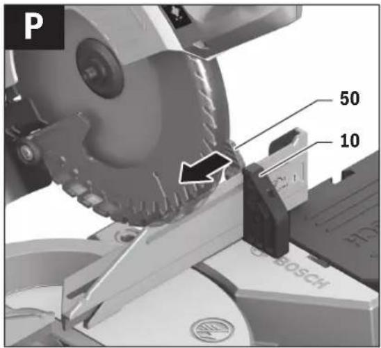
Sawing Workpieces of the Same Length (see figure P)
The material stop 10 can be used for easily sawing workpieces to the same length.
- Loosen the clamping lever 50 and set the material stop 10 to the required workpiece length.
- Retighten the clamping lever 50.
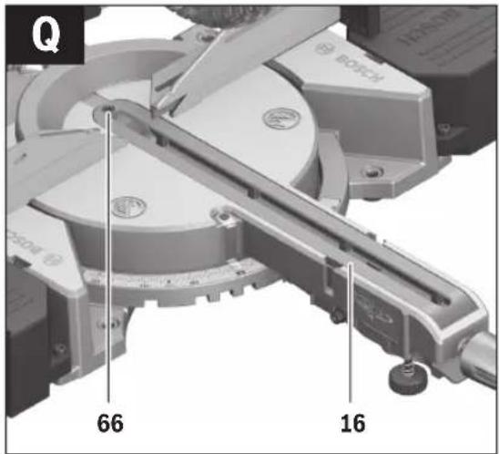
Replacing the Insert Plate (see figure Q)
The black insert plate 16 can become worn after prolonged use of the power tool.
Replace a defective insert plate.
- Bring the power tool into the working position.
- Unscrew the fastening screw 66 using the hex key 49 and remove the old insert plate.
- Insert the new insert plate and screw the fastening screw 66 in tight again.
Sawing Profile Strips
Profile strips/mouldings can be sawn in two different ways:
- Placed against the fence
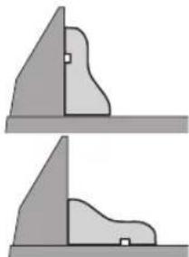
- Lying flat on the saw table
In addition, the cut can be performed with or without slide movement depending on the width of the profile strip/moulding.
Always make trial cuts with the mitre angle setting first on scrap wood.
Transport (see figure R)
Before transporting the power tool, the following steps must be carried out:
- Bring the machine into the transport position.
- Insert the flexible saw-table extensions 63 into the openings 64 of the power tool.
- Remove all accessories that cannot be mounted firmly to the power tool.
If possible, place unused saw blades in an enclosed container for transport.
- Always carry the power tool by its transport handle 2. When transporting the power tool, use only the transport devices and never use the protective devices.





Maintenance and Service
Maintenance and Cleaning
Before any work on the machine itself, pull the mains plug.
If the replacement of the supply cord is necessary, this has to be done by Bosch or an authorized Bosch service agent in order to avoid a safety hazard.
Cleaning
For safe and proper working, always keep the power tool and its ventilation slots clean.
The retracting blade guard must always be able to move freely and retract automatically. Therefore, always keep the area around the retracting blade guard clean.
Remove dust and chips after each working procedure by blowing out with compressed air or with a brush.
Clean the roller 24 regularly.
Accessories
| Article number | |
| Saw blades for wood | |
| Saw blade 216 x 30 mm, 24 teeth | 2 608 640 431 |
| Saw blade 216 x 30 mm, 48 teeth | 2 608 640 432 |
Saw blades for hardwood and composite materials
| Saw blade 216 x 30 mm, 60 teeth 2 608 640 433 |
After-sales Service and Application Service
Our after-sales service responds to your questions concerning maintenance and repair of your product as well as spare parts. Exploded views and information on spare parts can also be found under:
www.bosch-pt.com
Bosch's application service team will gladly answer questions concerning our products and their accessories.
In all correspondence and spare parts orders, please always include the 10-digit article number given on the nameplate of the product.
Great Britain
Robert Bosch Ltd. (B.S.C.)
P.O. Box 98
Broadwater Park
North Orbital Road
Denham
Uxbridge
UB9 5HJ
At www.bosch-pt.co.uk you can order spare parts or arrange the collection of a product in need of servicing or repair.
Tel. Service: (0344) 7360109
E-Mail: boschservicecentre@bosch.com
Ireland
Origo Ltd.
Unit 23 Magna Drive
Magna Business Park
City West
Dublin 24
Tel. Service: (01) 4666700
Fax: (01) 4666888
Australia, New Zealand and Pacific Islands
Robert Bosch Australia Pty. Ltd.
Power Tools
Locked Bag 66
Clayton South VIC 3169
Customer Contact Center
Inside Australia:
Phone: (01300) 307044
Fax: (01300) 307045
Inside New Zealand:
Phone: (0800) 543353
Fax: (0800) 428570
Outside AU and NZ:
Phone: +61 3 95415555
www.bosch-pt.com.au
www.bosch-pt.co.nz
Republic of South Africa
Customer service
Hotline: (011) 6519600
Gauteng - BSC Service Centre
35 Roper Street, New Centre
Johannesburg
Tel.: (011) 4939375
Fax: (011) 4930126
E-Mail: bsctools@icon.co.za
KZN - BSC Service Centre
Unit E, Almar Centre
143 Crompton Street
Pinetown
Tel.: (031) 7012120
Fax: (031) 7012446
E-Mail: bsc.dur@za.bosch.com
Western Cape - BSC Service Centre
Democracy Way, Prosperity Park
Milnerton
Tel.: (021) 5512577
Fax: (021) 5513223
E-Mail: bsc@zsd.co.za
Bosch Headquarters
Midrand, Gauteng
Tel.: (011) 6519600
Fax: (011) 6519880
E-Mail: rbsa-hq.pts@za.bosch.com
Disposal
The machine, accessories and packaging should be sorted for environmental-friendly recycling.

Do not dispose of power tools into household waste!
Only for EC countries:
According to the European Directive 2012/19/EU for Waste Electrical and Electronic Equipment and its implementation into national right, power tools that are no longer usable must be collected separately and disposed of in an environmentally correct manner.
Subject to change without notice.
Transport (see figure R)
Robert Bosch (France) S.A.S.
Laser Radiation Do not stare into beam Class 2 laser product
Stationary or flexible mounting
Bosch Service Center
Telegrafvej 3
2750 Ballerup
Spare parts can be ordered online or a repair order can be created at www.bosch-pt.dk.
Service Center phone: 44898855
Fax: 44898755
E-mail: vaerktoej@dk.bosch.com
Disposal
Bosch Service Center
Telegrafvej 3
2750 Ballerup
Denmark
Tel.: (08) 7501820 (within Sweden)
Fax: (011) 187691
Waste management
If the text on the warning sign is not in your language, you must stick a label in your language over this sign before using the product.

20 Drilling holes for mounting
21 Saw table
22 Quick-action clamp
23 Chip deflector
24 Guide roller
25 Locking screw for pull element
- lying flat on the saw table
34 cleaning the laser
• If the text of the warning plate is not in the language of your country, then, before the first use, stick the warning plate in the language of your country that is included in the package.
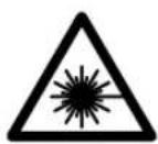
IEC 60825-1:2014
<1mW, 650 nm Laser Radiation
Do not stare into beam
Class 2 laser product
Robert Bosch Sp. z o.o.
BSC
Ul. Szyszkowa 35/37
02-285 Warszawa
Laser Radiation Do not stare into beam Class 2 laser product
Bosch Service Center PT
K Vápence 1621/16
692 01 Mikulov
IEC 60825-1:2014 <1mW, 650 nm Laser Radiation
Do not stare into beam
Class 2 laser product
IEC 60825-1:2014
<1mW, 650 nm Laser Radiation
Do not stare into beam
Class 2 laser product
Laser Radiation Do not stare into beam Class 2 laser product
IEC 60825-1:2014 <1mW, 650 nm Laser Radiation
Do not stare into beam
Class 2 laser product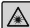
Service scule electrice
Strada Horia Măcelariu Nr. 30-34, sector 1
013937 Bucureşti
- легнали на масата
Service scule electrice
Strada Horia Măcelariu Nr. 30–34, sector 1
013937 Bucureşti, România
www.bosch-pt.com/bg/bg/
226 | Македонски
Бракуване
Laser Radiation Do not stare into beam Class 2 laser product
Laser Radiation Do not stare into beam Class 2 laser product
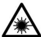
If the warning label text is not in your language, then stick the supplied label in your country's language over it before first use.
To set the horizontal miter angle, you must pull out the lever and turn the saw table until the angle indicator shows the desired miter angle.

When cutting vertical bevel angles with the saw, you must pull the movable fence outward.
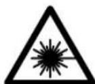
If the warning label text is not in your language, stick the supplied label in your national language over it before first use.
To set the horizontal miter angle, with the lever pulled out, turn the saw table so that the angle indicator points to the desired miter angle.

In addition, depending on the width of the profile strip, you can make cuts with or without the pull motion.
IEC 60825-1:2014 <1mW, 650 nm Laser Radiation
Do not stare into beam
Class 2 laser product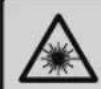
+968 99886794: Mobile
International Construction Solutions W L L
P.O. Box: 51 Doha
Qatar
+974 40065458: Phone
Laser Radiation Do not stare into beam Class 2 laser product
EasyVac 3
06033D10..

UniversalVac 15
06033D11..

AdvancedVac 20
06033D12..
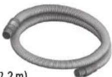

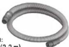
∅ 35 mm: 2 609 256 F29 (2.2 m)

∅ 35 mm: 2 609 256 F30 (2.2 m)
∅ 19 mm: 2 609 256 F38 (2 m)


2 609 256 F28

CE
I
| de | EU-KonformitätserklärungPaneelsäge Sachnummer | Wir erklären in alleiniger Verantwortung, dass die genannten Produkte allen einschlägigen Bestimmungen der nachfolgend aufgeführten Richtlinien und Verordnungen entsprechen und mit folgenden Normen übereinstimmen.Technische Unterlagen bei: * |
| en | EU Declaration of ConformitySliding Mitre Saw Article number | We declare under our sole responsibility that the stated products comply with all applicable provisions of the directives and regulations listed below and are in conformity with the following standards.Technical file at: * |
| fr | Déclaration de conformité UEScie à onglets N° d’articleradiale | Nous déclarons sous notre propre responsabilité que les produits décrits sont en conformité avec les directives, règlements normatifs et normes énumérés ci-dessous.Dossier technique auprès de : * |
| es | Declaración de conformidad UEIngletadora N° de articulotelescópica | Declaramos bajo nuestra exclusiva responsabilidad, que los productos nombrados cumplen con todas las disposiciones correspondientes de las Directivas y los Reglamentos mencionados a continuación y están en conformidad con las siguientes normas.Documentos técnicos de: * |
| pt | Declaração de Conformidade UESerra para painéis N.° do produto | Declaramos sob nossa exclusiva responsabilidade que os produtos mencionados cumprem todas as disposições e os regulamentos indicados e estão em conformidade com as seguintes normas.Documentação técnica pertencente à: * |
| it | Dichiarazione di conformità UETroncatrice radiale Codice prodotto | Dichiariamo sotto la nostra piena responsabilità che i prodotti indicati sono conformi a tutte le disposizioni pertinenti delle Direttive e dei Regolamenti elencati di seguito, nonché alle seguenti Normative.Documentazione Tecnica presso: * |
| nl | EU-conformiteitsverklaringRadiaalzaag Productnummer | Wij verklaren op eigen verantwoordelijkheid dat de genoemde producten voldoen aan alle desbetreffende bepalingen van de hierna genoemde richtlijnen en verordeningen en overeenstemmen met de volgende normen.Technisch dossier bij: * |
| da | EU-overensstemmelseserklæringKap- og geringssav Typenummer | Vi erklærer som eneansvarlige, at det beskrevne produkt er i overensstemmelse med alle gældende bestemmelser i følgende direktiver og forordninger og opfylder følgende standarder.Tekniske bilag ved: * |
| sv | EU-konformitetsförklaringPanelsåg Produktnummer | Vi förklarar under eget ansvar att de nämnda produkterna uppfyller kraven i alla gällande bestämmelser i de nedan angivna direktiven och förordningarnas och att de stämmer överens med följande normer.Teknisk dokumentation: * |
| no | EU-samsvarserklæringKapp- og gjæringssag Produktnummer | Vi erklærer under eneansvar at de nevnte produktene er i overensstemmelse med alle relevante bestemmelser i direktivene og forordningene nedenfor og med følgende standarder.Teknisk dokumentasjon hos: * |
| fi | EU-vaatimustenmukaisuusvakuutusKatkaisu- ja jilirisaha Tuotenumero | Vakuutamme täten, että mainitut tuotteet vastaavat kaikkia seuraavien direktivien ja asetusten asiaankuuluvia vaatimuksia ja ovat seuraavien standardien vaatimusten mukaisia.Tekniset asiakirjat saatavana: * |
| el | Δήλωση πιστότητας EEΦυλτσοπρίονο ΑριθμόςRadial ευρετηρίου | Δηλώνουμε με αποκλειστική μας ευθύνη, ότι τα αναφερόμενα προϊόντα αντιστοιχούν σε όλες τις σχετικές διατάξεις των πιο κάτω αναφερόμενων οδηγιών και κανονισμών και ταυτίζονται με τα ακόλουθα πρότυπα.Tεχνικά έγγραφα στη: * |
| tr | AB Uygunluk beyaniPanel testere Ürün kodu | Tek sorumlu olarak, tanımlanan ürünün aşağıdaki yönetmelik ve direktiflerin geçerli bütün hükümetlerine ve aşağıdaki standartlara uygun olduğunu beyan ederiz.Teknik belgelerin bulunduğu yer: * |
| de | EU-KonformitätserklärungPaneelsäge Sachnummer | Wir erklären in alleiniger Verantwortung, dass die genannten Produkte allen einschlägigen Bestimmungen der nachfolgend aufgeführten Richtlinien und Verordnungen entsprechen und mit folgenden Normen übereinstimmen.Technische Unterlagen bei:* | |
| en | EU Declaration of ConformitySliding Mitre Saw Article number | We declare under our sole responsibility that the stated products comply with all applicable provisions of the directives and regulations listed below and are in conformity with the following standards.Technical file at:* | |
| fr | Déclaration de conformité UEScie à onglets radiale | N° d'article | Nous déclarons sous notre propre responsabilité que les produits décrits sont en conformité avec les directives, règlements normatifs et normes énumérés ci-dessous.Dossier technique auprès de:* |
| es | Declaración de conformidad UEIngletadora telescópica | N° de artículo | Declaramos bajo nuestra exclusiva responsabilidad, que los productos nombrados cumplen con todas las disposiciones correspondientes de las Directivas y los Reglamentos mencionados a continuación y están en conformidad con las siguientes normas.Documentos técnicos de:* |
| pt | Declaração de Conformidade UESerra para painéis N.° do produto | Declaramos sob nossa exclusiva responsabilidade que os produtos mencionados cumprem todas as disposições e os regulamentos indicados e estão em conformidade com as seguintes normas.Documentação técnica pertencente à:* | |
| it | Dichiarazione di conformità UETroncatrice radiale | Codice prodotto | Dichiariamo sotto la nostra piena responsabilità che i prodotti indicati sono conformi a tutte le disposizioni pertinenti delle Direttive e dei Regolamenti elencati di seguito, nonché alle seguenti Normative.Documentazione Tecnica presso:* |
| nl | EU-conformiteitsverklaringRadiaalzaag | Productnummer | Wij verklaren op eigen verantwoordelijkheid dat de genoemde producten voldoen aan alle desbetreffende bepalingen van de hierna genoemde richtlijnen en verordeningen en overeenstemmen met de volgende normen.Technisch dossier bij:* |
| da | EU-overensstemmelseserklæringKap- og geringssav | Typenummer | Vi erklærer som eneansvarlige, at det beskrevne produkt er i overensstemmelse med alle gældende bestemmelser i følgende direktiver og forordninger og opfylder følgende standarder.Tekniske bilag ved:* |
| sv | EU-konformitetsförklaringPanelsåg | Produktnummer | Vi förklarar under eget ansvar att de nämnda produkterna uppfyller kraven i alla gällande bestämmelser i de nedan angivna direktiven och förordningarnas och att de stämmer överens med följande normer.Teknisk dokumentation:* |
| no | EU-samsvarserklæringKapp- og gjæringssag | Produktnummer | Vi erklærer under eneansvar at de nevnte produktene er i overensstemmelse med alle relevante bestemmelser i direktivene og forordningene nedenfor og med følgende standarder.Teknisk dokumentasjon hos:* |
| fi | EU-vaatimustenmukaisuusvakuutusKatkaisu- ja jiiri-saha | Tuotenumero | Vakuutamme täten, että mainitut tuotteet vastaavat kaikkia seuraavien direktivien ja asetusten asiaankuuluvia vaatimuksia ja ovat seuraavien standardien vaatimusten mukaisia.Tekniset asiakirjat saatavana:* |
| el | Δήλωση πιστότητας EEΦαλτσοπρίονο Radial | Αριθμόςευρετηρίου | Δηλώνουμε με αποκλειστική μας ευθύνη, ότι τα αναφερόμενα προϊόντα αντιστοιχούν σε όλες τις σχετικές διατάξεις των πιο κάτω αναφερόμενων οδηγιών και κανονισμών και ταυτίζονται με τα ακόλουθα πρότυπα.Tεχνικά έγγραφα στη:* |
| tr | AB Uygunluk beyaniPanel testere | Ürün kodu | Tek sorumlu olarak, tanımlanan ürünün aşağıdaki yönetmelik ve direktiflerin geçerli bütün hükümlerine ve aşağıdaki standartlara uygun olduğunu beyan ederiz.Teknik belgelerin bulunduğu yer:* |

| II | CE | ||
| pl | Deklaracja zgodności UE Piła do cięcia paneli Numer katalogowy | Oświadczamy z pełną odpowiedzialnością, że niniejsze produkty odpowiadają wszystkim wymaganiom poniżej wyszczególnionych dyrektyw i rozporządzeń, oraz że są zgodne z następującymi normami. Dokumentacja techniczna:* | |
| cs | EU prohlášení o shodě Pokosová pila se zákluzem | Objednací číslo | Prohlašujeme na výhradní zodpovědnost, že uvedený výrobek splňuje všechna příslušná ustanovení níže uvedených směrnic a nařízení a je v souladu s následujícími normami: Technické podklady u:* |
| sk | EÚ vyhlásenie o zhode Píla na obklady Vecné číslo | Vyhlasujeme na výhradní zodpovednosť, že uvedený výrobok splňa všetky príslušné ustanovenia nižšie uvedených smerníc a nariadení a je v súlade s n as l e d u j ú c i m i n o r m a m i : Technické podklady má spoločnosť:* | |
| hu | EU konformitási nyilatkozat Lapfűrész | Cikkszám | Egyedüli felelőséggel kijelentjük, hogy a megnevezett termékek megfelelnek az alábbiakban felsorolásra kerülő irányelvek és rendeletek valamennyi idevágó előírásainak és megfelelnek a következő szabványoknak. Műszaki dokumentumok megőrzési pontja:* |
| ru | Заявление о соответствии EC Панельная пила | Товарный No | Мы заявляем под нашу единоличную ответственность, что названные продукты соответствуют всем действующим предписаниям нижеуказанных директив и распоряжений, а также нижеуказанных норм. Техническая документация хранится y:* |
| uk | Заява про відповідність ЄС Панельна пила | Товарний номер | Мизаявляємо під нашу одноособову відповідальність, що названі вироби відповідають усім чинним положеням нищеозначених директив і розпоряджень, а також нижчеозначеним нормам. Технічна документація зберігається y:* |
| kk | EO сәйкестік мағлумдамасы Панельдік ара | Өнім нөмірі | Өз жауапкершілікпен біз аталған өнімдер төменде жзылған директикалар мен жарлықтардың тиісті қағидаларына сәйкестігін және төмендегі нормаларға сай екенін білдіреміз. Техникалық құжаттар:* |
| ro | Declarație de conformitate UE Ferăstrău circular staționar | Număr de identificare | Declarăm pe proprie răspundere că produsele mentionate corespund tuturor dispozițiilor relevante ale directivelor și reglementărilor enumerate în cele ce urmează și sunt în conformitate cu următoarele standarde. Documentație tehnică la:* |
| bg | EC декларация за съответствие Циркуляр за ламперия | Каталожен номер | С пълна отговорностние декларираме, че посочените продукти отговарят на всички валидни изисквания на директивите и разпоредбите по-долу и съответства на следните стандарти. Техническа документация при:* |
| mk | EU-Изјава за сообразност Пила за оплата | Број на дел/артикл | Со целосна одговорност изјавуваме, дека опишаните производи се во согласност со сите релевантни одредби на следните регулативи и прописи и се во согласност со следните норми. Техничка документација кај:* |
| sr | EU-izjava o usaglašenosti Testera za panel | Broj predmeta | Na sopstvenu odgovornost izjavljujemo, da navedeni proizvodi odgovaraju svim dotičnim odredbama naknadno navedenih smernica u uredaba i da su u skladu sa sledećim standardima. Tehnička dokumentacija kod:* |
| sl | Izjava o skladnosti EU Žaga za rezanje panelnih plošć | Številka artikla | Izjavljamo pod izključno odgovornostjo, da je omenjen izdelek v skladu z vsemi relevantnimi določili direktiv in uredb ter ustreza naslednjim standardom. Tehnična dokumentacija pri:* |
| hr | EU izjava o sukladnosti Pila za panel ploče | Kataloški br. | Pod punom odgovornošću izjavljujemo da navedeni proizvodi odgovaraju svim relevantnim odredbama direktiva i propisima navedenima u nastavku i da su sukladni sa sljedećim normama. Tehnička dokumentacija se može dobiti kod:* |
| et | EL-vastavusdeklaratsioon Järkamissaag | Tootenumber | Kinnitame ainuvastutajatena, et nimetatud tooted vastavad järgnevalt loetletud direktiivide ja määruste köikidele asjaomastele nöuetele ja on kooskõlas järgmiste normidega. Tehnilised dokumendid saadaval:* |
CE
III


- PCM
- BOSCH
- DEUTSCH
- SAFETY INSTRUCTIONS
- GENERAL POWER TOOL SAFETY WARNINGS
- SAVE ALL WARNINGS AND INSTRUCTIONS FOR FUTURE REFERENCE
- WORK AREA SAFETY
- ELECTRICAL SAFETY
- PERSONAL SAFETY
- POWER TOOL USE AND CARE
- ENGLISH
- SERVICE
- SAFETY WARNINGS FOR MITRE SAWS
- SYMBOLS
- SYMBOLS AND THEIR MEANING
- PRODUCT DESCRIPTION AND SPECIFICATIONS
- INTENDED USE
- PRODUCT FEATURES
- NOISE INFORMATION
- ASSEMBLY
- DELIVERY SCOPE
- MOUNTING INDIVIDUAL COMPONENTS
- MOUNTING STATIONARY SAW-TABLE EXTENSIONS (SEE FIGURE A)
- STATIONARY OR FLEXIBLE MOUNTING
- MOUNTING TO A WORKING SURFACE (SEE FIGURE B)
- FLEXIBLE MOUNTING (NOT RECOMMENDED!) (SEE FIGURE C)
- DUST/CHIP EXTRACTION
- INTEGRATED DUST EXTRACTION (SEE FIGURE D)
- EXTERNAL DUST EXTRACTION
- CHANGING THE TOOL (SEE FIGURES E1–E4)
- REMOVING THE SAW BLADE
- MOUNTING THE SAW BLADE
- OPERATION
- TRANSPORT SAFETY (SEE FIGURE F)
- RELEASING THE MACHINE (WORKING POSITION)
- SECURING THE MACHINE (TRANSPORT POSITION)
- CLAMPING THE WORKPIECE (SEE FIGURES G1-G3)
- VERTICAL CLAMPING
- HORIZONTAL CLAMPING
- LOOSENING THE WORKPIECE
- EXTENDING THE SAW TABLE (SEE FIGURE H)
- COMPOUND MITRE CUTS
- ADJUSTING MITRE ANGLES (SEE FIGURE I)
- LEFT RIGHT
- ADJUSTING BEVEL ANGLES
- ADJUSTING THE LEFT-HAND BEVEL ANGLE RANGE (SEE FIGURES J1-J2)
- ADJUSTING THE COMPLETE BEVEL ANGLE RANGE (SEE FIGURE J3)
- ADJUSTING STANDARD BEVEL ANGLES (SEE FIGURE J4)
- STARTING OPERATION
- SWITCHING ON (SEE FIGURE K)
- SWITCHING OFF
- WORKING ADVICE
- GENERAL SAWING INSTRUCTIONS
- MARKING THE CUTTING LINE (SEE FIGURES L1-L2)
- POSITION OF THE OPERATOR (SEE FIGURE M)
- PERMISSIBLE WORKPIECE DIMENSIONS
- SAWING WITHOUT SLIDE MOVEMENT (CUTTING OFF) (SEE FIGURE N)
- SAWING WITH SLIDE MOVEMENT
- ADJUSTING THE DEPTH STOP (SAWING GROOVES) (SEE FIGURE O)
- SAWING WORKPIECES OF THE SAME LENGTH (SEE FIGURE P)
- REPLACING THE INSERT PLATE (SEE FIGURE Q)
- SAWING PROFILE STRIPS
- TRANSPORT (SEE FIGURE R)
- MAINTENANCE AND SERVICE
- MAINTENANCE AND CLEANING
- CLEANING
- AFTER-SALES SERVICE AND APPLICATION SERVICE
- WWW.BOSCH-PT.COM
- GREAT BRITAIN
- IRELAND
- AUSTRALIA, NEW ZEALAND AND PACIFIC ISLANDS
- REPUBLIC OF SOUTH AFRICA
- CUSTOMER SERVICE
- GAUTENG - BSC SERVICE CENTRE
- KZN - BSC SERVICE CENTRE
- WESTERN CAPE - BSC SERVICE CENTRE
- BOSCH HEADQUARTERS
- DISPOSAL
- ONLY FOR EC COUNTRIES
- WASTE MANAGEMENT
- CLEANING THE LASER
- МАКЕДОНСКИ
- БРАКУВАНЕ
- CE
- III
Brand : BOSCH
Model : PCM 8 SD
Category : Saw