
MAGICSAFE MSG 150 - Portable Refrigerator DOMETIC - Free user manual and instructions
Find the device manual for free MAGICSAFE MSG 150 DOMETIC in PDF.
| Product type | Gas detector |
| Brand | DOMETIC |
| Model | MAGICSAFE MSG 150 |
| Dimensions (W x H x D) | 80 x 156 x 51 mm |
| Power supply | 10-32 V DC |
| Power consumption | 1.3 W |
| Operating temperature | 0 °C to +40 °C |
| Alarm sound level | Approx. 85 dB at 3 m |
| Protection type | IP 20 |
| Detected gases | Ether, chloroform, butane, ethane, trichloroethylene |
| LED indicators | Green LED (ready), orange LED (fault), red LED (alarm) |
| Functions | Narcotic gas detection, audible and visual alarm, monthly test, mute function |
| Connection | 12/24 V socket or fixed connection with additional switch |
| Accessory compatibility | External siren (9101600008), RV-AMP-SW switch, MS660/DVS90 alarm systems |
| Maintenance | Clean with a damp cloth; do not use detergents |
| Warranty | Manufacturer standard, contact after-sales service |
| Safety instructions | Use only in vehicles with engine off; install near sleeping area |
| Package contents | Gas detector, mounting plate, fixing material |
| Disposal | Recycle according to local regulations |
Frequently Asked Questions - MAGICSAFE MSG 150 DOMETIC
User questions about MAGICSAFE MSG 150 DOMETIC
0 question about this device. Answer the ones you know or ask your own.
Ask a new question about this device
Download the instructions for your Portable Refrigerator in PDF format for free! Find your manual MAGICSAFE MSG 150 - DOMETIC and take your electronic device back in hand. On this page are published all the documents necessary for the use of your device. MAGICSAFE MSG 150 by DOMETIC.
USER MANUAL MAGICSAFE MSG 150 DOMETIC
COMPLEMENTARYPRODUCTS
ALARM SYSTEMS
MSG150
EN
Gas detector
Installation and Operating Manual 10
DE
Gasmelder
Please read this instruction manual carefully before installation and first use, and store it in a safe place. If you pass on the product to another person, hand over this instruction manual along with it.
Table of contents
1 Explanation of symbols. 11
2 Safety and installation instructions 11
3 Scope of delivery 12
4 Accessories/expansions 13
5 Intended use. 13
6 Technical description 13
7 Mounting the MagicSafe MSG150 14
8 Connecting the gas detector 14
9 Operating the MagicSafe MSG150. 17
10 Alarm. 18
11 Troubleshooting 19
12 Maintaining and cleaning the gas detector 19
13 Warranty 20
14 Disposal. 20
15 Technical data. 20
1 Explanation of symbols

WARNING!
Safety instruction: Failure to observe this instruction can cause fatal or serious injury.

CAUTION!
Safety instruction: Failure to observe this instruction can lead to injury.

NOTICE!
Failure to observe this instruction can cause material damage and impair the function of the product.

NOTE
Supplementary information for operating the product.
2 Safety and installation instructions
The manufacturer accepts no liability for damage in the following cases:
- Damage to the product resulting from mechanical influences and excess voltage
- Alterations to the product without express permission from the manufacturer
- Use for purposes other than those described in the operating manual
2.1 General safety

WARNING!
- Only use the device as intended.
- Disconnect the device from the mains:
Before cleaning and maintenance
After use
Before changing a fuse
- The device may not be used if the device itself or the connection cable are visibly damaged.
- If the power cable for this device is damaged, it must be replaced by the manufacturer, customer service or a similarly qualified person in order to prevent safety hazards.
- This device may only be repaired by qualified personnel. Inadequate repairs may cause serious hazards.
-
This device can be used by children aged 8 years or over, as well as by persons with diminished physical, sensory or mental capacities or a lack of experience and knowledge, providing they are supervised, or have been taught how to use the device safely and are aware of the resulting risks.
-
Electrical appliances are not toys.
Always keep and use the device out of the reach of children.
Children must be supervised to ensure that they do not play with the device.

NOTICE!
- Before start-up, check that the voltage specification on the type plate is the same as that of the power supply.
- Never pull the plug out of the socket by the connection cable.
- Store the device in a dry and cool place.
2.2 Operating the device safely
- Only operate the appliance in vehicles when the engine is switched off.
- Do not operate the device outdoors.
- Once a month and after longer periods of disuse, test the function of the device by pressing the (fig. 3 4, page 5) pushbutton.
3 Scope of delivery
| No. in fig. 2, page 3 | Quan-tity | Description | Ref. no. |
| 1 | 1 | Gas detector | 9600000368 |
| 2 | 1 | Installation panel | |
| - | 1 | Fastening material |
4 Accessories/expansions
| Description | Ref. no. |
| External siren | 9101600008 |
| Additional switch | RV-AMP-SW |
5 Intended use
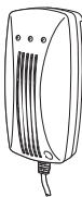
MagicSafe MSG150 (ref. no. 9600000368) is a gas detector which detects noxious gases before they can take effect. MSG150 has been designed for use in vehicles to detect noxious gases which have an ether, chloroform, butane, ethane or trichloroethane basis.

NOTE
With a voltage range of 10 to 32V = , the gas detector is suitable for use in both cars and trucks.
6 Technical description
The MSG 150 gas detector can be used as a warning device in many areas to detect gases with a narcotic effect before they can take effect.
The gas detector contains a sensor and an acoustic signal generator and is connected to a 12/24V = 1 voltage supply, e.g. the cigarette lighter in a vehicle.
In addition to this, the gas detector contains an internal relay. An external siren of signal lamp can be connected to this.
The connection terminal for the relay connection can be found on the back of the gas detector (fig. 3, page 4).
| No. in fig. 3, page 4 | Description |
| 1 | Relay contact 1 |
| 2 | Relay contact 2 |
You can operate the gas detector in three ways:
- As single device
In combination with the external siren (ref. no. 9101600008) - In combination with the MagicSafe alarm system MS660 or DVS90
7 Mounting the MagicSafe MSG150
7.1 Tools required
For mounting you will require the following tools:
- Measuring ruler (fig. 1, page 3)
- Centre punch (fig. 1 2, page 3)
- Hammer (fig. 13, page 3)
- Drill bit set (fig. 1 4, page 3)
Electric drill (fig. 1 5, page 3) - Screwdriver (fig. 1 6, page 3)
7.2 Mounting the gas detector
Note the following when selecting a place to fit the gas detector:
Note the length of the cable.
- The gas detector should be mounted in the vicinity of the sleeping area at the height of the mattress.
Select a suitable installation location.

NOTICE!
Before making any drill holes, ensure that no electrical cables or other parts can be damaged by drilling.
Hold the mounting panel on the chosen location and mark the two drill holes (fig. 5, page 5).
Screw the mounting panel tight with the two self-tapping screws (fig. 6, page 5).
Insert the gas detector on the mounting panel (fig. 7, page 5).
Insert the plug of the gas detector in the socket of your 12/24 V=volte supply.
The green LED on the gas detector (fig. 8 1, page 5) flashes for approx. 10min . The sensor is then brought to the operating temperature.
When the green LED glows constantly, the gas detector is ready for operation.
8 Connecting the gas detector
8.1 As a single device
If you use the gas detector as a single device, you can either
- Switch it on with the 12/24V = plug
- Switch it on with the RV-AMP-SW additional switch (accessory), if there is no 12/24V = socket in the sleeping area.
Connecting the gas detector using the 12 / 24V = - plug
Insert the 12 / 24V = = plug into a socket with a constant 12 / 24V = = supply. This socket should be connected with the vehicle battery.
An acoustic signal sounds and the green LED (fig. 8 1, page 5) flashes for approx. 10 minutes. During this time the gas detector conducts a system test and the sensor is brought to operating temperature.
Connecting the gas detector so that it is hardwired
If you wish to give the gas detector a permanently wired connection and switch it on with the RV-AMP-SW additional switch, please use the circuit diagram fig. 9, page 6.
Disconnect the 12 / 24V = = plug from the cable.
Remove around 10~cm of the outer insulation on the end of the cable.
Connect the black, yellow and orange cable to the bodywork earth (terminal 31).
Connect the red cable to the output of the RV-AMP-SW additional switch.
Connect the input of the switch with a 1 A fuse to the positive battery pole.
8.2 In combination with the external siren (ref. no. 9101600008)
If you wish to connect the gas detector with the external siren, please use the circuit diagram fig. 10, page 6.
Mounting the external siren
The external siren can be mounted in the engine compartment.
When mounting it, ensure that the installation location is
- Not in an area exposed to splashing water
- Not near the exhaust system
- Cannot be accessed from underneath the vehicle, to ensure that it cannot be sabotaged.
Mount the external siren with the acoustic horn facing downwards.
Connecting the alarm siren

NOTE
If your vehicle does not have a 12V = - continuous positive cable in the mounting area, you can also connect the input to the vehicle battery using a 1 A fuse.
Connect the black cable of the siren to the bodywork earth (terminal 31).
Connect the red cable of the siren to the relay contact 2 (fig. 3 2, page 4).
Connect the relay contact 1 (fig. 3 1, page 4) to the 12V = ~ continuous positive. The cable must be fused with at least a 1 A fuse.
8.3 In combination with an MS660 or DVS90 alarm system
If you wish to use the gas detector in combination with
- the MS660 alarm system, please use the circuit diagram fig. 11, page 7
- the DVS90 alarm system, please use the circuit diagram fig. 12, page 8

NOTICE!
If you are combining the MagicSafe MSG150 with the DVS90 alarm system, you need to configure the alarm system as follows:
- Set output 2.6 to "Status-Armed" and input 2.5 to "Trigger".
Gas detector with MS660
Disconnect the 12V = = plug from the cable.
Remove around 10~cm of the outer insulation on the end of the cable.
Connect the black cable to the bodywork earth (terminal 31).
Connect the yellow and orange cable (fig. 11, page 7) with the white cable of the alarm system (pin 15, 15-pin plug).
Connect the red cable with 12V = = continuous positive. The cable must be fused with at least a 1 A fuse.
If the gas detector is to be switched as the main alarm on the MS660 external alarm system, connect
- relay contact 1 (fig. 11, page 7) to the bodywork earth (terminal 31) and
- relay contact 2 (fig. 11, page 7) to the grey/white cable (pin 4, 9-pin plug) of the alarm system.
Gas detector with DVS90
Disconnect the 12 / 24V = = plug from the cable.
Remove around 10~cm of the outer insulation on the end of the cable.
Connect the black, yellow and orange cable to the bodywork earth (terminal 31).
Connect the red cable with the green/red cable (P2, pin 6 (fig. 12, page 8). The cable must be fused with at least a 1 A fuse.
If the gas detector is to be switched as the main alarm on the DVS90 external alarm system, connect
- relay contact 1 (fig. 12, page 8) to the bodywork earth (terminal 31) and
- relay contact 2 (fig. 12, page 8) to the black/grey cable (P2, pin 5) of the alarm system.
9 Operating the MagicSafe MSG 150
To avoid false alarms caused by cooking, using deodorants, heavy smoking and alcohol consumption, the vehicle should be ventilated thoroughly before retiring to bed and then the gas detector should be switched on.
| No. in fig. 6, page 5 | description |
| 1 | Green LED The green LED flashes for approx. 10 minutes after the gas detector has been connected to a voltage supply or switched on with the RV-AMP-SW auxiliary switch. While the LED is flashing, the sensor is brought to the operating temperature. When the green LED glows constantly, the gas detector is ready for operation. |
| 2 | Orange LED: The orange LED glows if a fault occurs. |
| 3 | Red LED (alarm) The red LED flashes if an alarm has been triggered. In addition to this, a siren sounds an alarm signal. (See also chapter “Alarm” on page 18.) |
| 4 | Pushbutton This pushbutton is a test button and also mutes the system. Test pushbutton > Press this pushbutton once a month or after extended periods of disuse to check the system is functioning. ✓ The orange and red LEDs flash and a siren sounds. Mute switch > Press this pushbutton if you wish to switch off the sound during an alarm. ✓ The red LED continues flashing and a brief signal sounds every 45 seconds. Then the system is armed again. |
Switching on the MSG150 as a single device or in combination with the external siren (ref. no. 9101600008)
Insert the 12 / 24V = - plug in a socket or switch on the gas detector with the RV-AMP-SW auxiliary switch.
An acoustic signal sounds and the green LED (fig. 8 1, page 5) flashes for approx. 10 minutes. During this time the gas detector conducts a system test and the sensor is brought to operating temperature.
If an alarm occurs, an acoustic signal sounds over the internal siren and the red LED (fig. 8 3, page 5) glows. If the external siren is connected, an additional acoustic signal sounds over the external siren.
To interrupt the internal alarm, press the pushbutton (fig. 8 4, page 5).
Switching on the MSG150 in combination with the MS660 or DVS90
Switch the MS660 or DVS90 alarm system on as usual: On the remote control of the respective device, press
- the lower button (MS660)
- the NO button of the vehicle or additional hand transmitter (DVS90).
An acoustic signal sounds and the green LED (fig. 8 1, page 5) flashes for approx. 10 minutes. During this time the gas detector conducts a system test and the sensor is brought to operating temperature.
If an alarm occurs, an acoustic signal sounds over the internal siren and the red LED (fig. 8 3, page 5) glows. The internal relay sends an earth signal to the alarm input of the external alarm system. The external alarm system immediately triggers an external alarm using the vehicle indicators and the vehicle horn or siren.
To interrupt the internal alarm, press the pushbutton (fig. 8 4, page 5).
To deactivate the external alarm, press the following on the remote control of the respective device:
The top button (MS660)
- The NC button of the vehicle or additional hand transmitter (DVS90).
10 Alarm
If an alarm is signalled, proceed as follows:
Determine the cause of the alarm immediately.
Instruct children and anybody still asleep to leave the vehicle or boat.
Open all doors and windows as quickly as possible.
Avoid striking matches or any naked flames and turn off any sources of combustion immediately.
Turn off all gas-powered devices.
Avoid causing sparks (do not use any electrical switches).
Rectify the cause or leave the vehicle or the boat.
False alarm
For your safety, the gas detector is set to be very sensitive. For this reason the sensor also reacts to other gaseous media. Using aerosols (e.g. propellants in spray cans) or thick tobacco smoke, heavy alcohol fumes or steam arising from cooking can trigger an alarm even though no gas or anaesthetic gas is present.
11 Troubleshooting
If the device is not ready for operation (the green LED does not glow), proceed as follows:
Make sure the power supply is 12 or 24V =
If the voltage is less than this, or the voltage supply has been interrupted, the gas detector does not function.
Check the fuse in the plug, if the gas detector is connected using a 12V = = plug.
Checking the fuse in the 12/24 V--- plug
In the tip of the plug, there is a fuse to protect the gas detector.
If the thin metal connection in the middle between the two metal caps is broken, the fuse is defective and must be replaced.

NOTICE!
Make sure that you only use the same fuse type in the plug. Damage to the device resulting from using inappropriate fuse types is excluded from guarantee claims under the terms of the warranty.
To replace the fuse, proceed as follows:
Pull the adapter sleeve (fig. 4, page 4) off of the plug.
Unscrew the screw (fig. 4 5, page 4) out of the upper half of the housing (fig. 4 1, page 4).
Carefully lift the upper half of the housing off the lower half (fig. 4 6, page 4).
Take out the contact pin (fig. 4 3, page 4).
Replace the defective fuse (fig. 4 2, page 4) with a new fuse that has the same rating.
Re-assemble the plug in the reverse order.
12 Maintaining and cleaning the gas detector

NOTICE!
Do not use sharp or hard objects or cleaning agents for cleaning as these may damage the product.
Occasionally clean the product with a damp cloth.
13 Warranty
The statutory warranty period applies. If the product is defective, please contact the manufacturer's branch in your country (see the back of the instruction manual for the addresses) or your retailer.
For repair and guarantee processing, please include the following documents when you send in the device:
- A copy of the receipt with purchasing date
- A reason for the claim or description of the fault
14 Disposal
Place the packaging material in the appropriate recycling waste bins wherever possible.

If you wish to finally dispose of the product, ask your local recycling centre or specialist dealer for details about how to do this in accordance with the applicable disposal regulations.
15 Technical data
| MagicSafe MSG150 | |
| Ref. no.: | 9600000368 |
| Dimensions (W x H x D): | 80 x 156 x 51 mm |
| Input voltage range: | 10 V= to 32 V= |
| Power consumption: | 1.3 W |
| Operating temperature: | 0 °C to +40 °C |
| Signal volume: | Approx. 85 dB at a distance of 3 m |
| Protection class: | IP 20 |
Approvals


6 Description technique
I3roTOBHTeH He HecET HnKaKo OTBeTcBEHOCTHaYuepe6 B CneDyUOxN cnyuaX:
- Поврждениюкту ИЗ-3a меничесхв ВОздевскийпеганяжени
- 13mehenbB npdykTe, BInOpHeHbIe 6e3 OndHO3HaunHO pa3peuHn H3rotOBHTen
- UcnoIb3OBAHnE B cIeIax, OTNIuHbIX OYka3aHHbIX DaHHO INHCTpyKUIN
2.1 OchoBhpie yKa3aHnno TeXnKe 6e3OnaNochOCTn

IPEyIpyEKeHHeI
- Icnojbyte np6op tobko no ha3naueHIO.
- OToCoeDnHnTe yCTpoNCTBO OT cETn
-пени Каддочисткои ухдом
- nocne kaxdoIocnOBAHn
- nepei 3ameHoi npedoxpaHITeH
3aepaaetcBAoNTb yctpoiCTBO Bpa60Ty,ecnO OHO nIN CoeHNHTbHbIKa6ebIb NMeHOT BUNIMbIE NOBpeXDeHNA.
B cyuye noBpexdeHnIHTaOIOE KAbENaDAnHORo yCTPOrCTBa OHO - BO 366eHAHe OAnOHcTei - DIOXNo 6bTy 3AmEHeNo hTROBtEnEM, cepBCHbIM ueHTPOM IIN IMEOUIM AHANOITHYKO KBAIINDFKANIOE NEPCOAHONJ.
- Pemont dAnHOrO yctpoCTBa pa3pe7aetcBA BInOnHb ToIbKO cneuaHnCTAm. HenpaBnBHO BInOnHeHHb pemont Moxtet npBODHTK Cepbe3HbM ONaCHOCTM.
3TOyCTPOICTBOMOXETNCIOJIb3OBAbTcBdTeBIMnC8-MNNETNCTAPJe,aTAKeNIUAMn CTOPAHNEHbIMnΦIN3YueCKMn,CEHCOPbHMnYNMCTBENHbIMnCNOOC6HOCTRMn INPi NpHEoCTaKe Heo6XoJIMIMO ObTIa N3AHNtOToNTOKIO NO pIpcmOTPOM ININ NOCTe PPOOXoJENHCTpykTaNa POe3OAnOHMYCNIOb3OBAHNIO yTOPOICTBa,ECIN OHIOHNMAOT ONACHOIn,KOTOpBIE pIN3OTMOIOT BO3NHKHyTb.
- 3neKtpoPn6OpbI He ABJIOTcIeTCKMm nrgyPkAmn!
IIO3OMy xpaHnte INCnONb3yUte pnp6Op B HeNOCTynHom dINr DeTeM MeTe.
3aTebMn Heo6xOIMMOIOCToHNO CneiHTb, YTO6bl He OOnyckaTb IVN VrpbC yCTPOIcTBOM.

BHIMAHHE!
- Ipeed BBODOM B3KcPnYatauHc CpabHnTe 3NaueHnHa npRaeHnya, yka3aHHbIe Ha 3aBOJCKoT a6nUyKe, cXapakTepcNtKAMn IMeUJIeOeroc NCTOCHNk PNTaHn.
He bItacknBaIte uTekep n3 po3eTKn 3a nTAtoUm K6ebNb.
XpaHnTe npn6Op B cyxom, npoxnaHOM MeCTe.
2.2 TexHnka 6e3oNaChocTh npHa pa6ote npH6opa
-ПользуITEсь пибором в abTomоБиNE TOЛьКО пи ВblкIOчЕнHom DBИгATENE.
He3KcnpnyatnpyIte npu6Op IOd OTkpblm He6om.
PaB MecaH n oce dIInTeNbHbIX nepepbBOB B pa6ote npOBepaTpa6Otu np6Opy haxaTMek KhoKn (pnc. 3 4, ctp. 5).
3 KOMIIJEKT IOCTABKIN
| № ha pnc. 2, ctp. 3 | KoI- BO | HannMeNoBaHne | Apt. № |
| 1 | 1 | Сигнанлзатор ragа | 9600000368 |
| 2 | 1 | Мотжнaya пала | |
| - | 1 | Крелений мaterpillar |
4 Akceccyapbl/pacupeHHa
| Наменоваиме | Apr. № |
| Вnevшая сирера | 9101600008 |
| Донорител新股ы вьклочател | RV-AMP-SW |
5 IcnoIb3ObaHne no Ha3HaueHnIO
MagicSafe MSG150 (apt. N9 9600000368) npectabniet co6o cnHanntopr r3a, koTobny paccno3haetnapKOTNECKHnBpIeNkE, yem OHn HauHT npO8nBTb CBOE deNCTBneMSG150
PACCCHAn HA pPmENHeNe B A bTOMO6JX PAPC03HABAHNAHapKOTnuecknx RaOB Ha 6a3e
3fnpra, xNpOPOFOpMa, 6yTaHa, 3TaHa n TpIXNOpTInHeNa.

YKA3AHHE
Bnaroapra Dnana3OHy HnpanjeHnIOT 10 Do 32 B= CnHnAin3atop Ra3a MoKeT nCOnnb3OBaTbCa KaB rpy3OBx, TaK N B PnKobix ABtOMo6nIax.
6 TexHHueckoe OINcaHne
CunHuaH3atopraaMSG150MoXet6bYbTnpIMHeNBeKauCTeByNHUBePcAnbHOrO CnHuaHbHoro npi6OpaIpaCno3HaBnHaHapKOTuecknx Ra3OB ppeJe, cem OHn HauHyT npoBHTcBoe DeIcTBne.
CnHnHa3atop r3a nMeet dAtuK, a TAKe AkyctuYeCKn CnHnHa3atOp, n PnpcoEiHReTc K nCTOHy HnPaJxHeNIA 12/24 B==, HnPImep, K npKypBATEIO ABTOMo6InI.
Kpome Toro, CnHann3atop rataa HmeeT BHytpene, K KOTOpMoy MoXHO, HApnPmep, npncoeHHbBHeuHIO CupeHy NIN CNHbHyI NaMny.
Писоелнгельни зддп рисоелненя К реонхадутca на заднй ссторе cnHnna3atopa ra3a (pnc. 3, ctr. 4).
MOHTAX BHEWHei CnpeHbI
BHeuHIO CnpeHy MoXHO yCTaHOBNTb B IOJaNtOHm IpOcTpaHCTBe.
Bb6epnte MeTo MOHTaxa TAK, UTO6bOHO
He HaxOINIOB B3OHe IOnaDaHn8 6pb3r
He HaxoDInIOcB 60N3N BbIyCkHOrO KOJIneKToP a
He 6bIIO DOCTynHO C HIXHEn CTOpOHy, YTO6bl IpeDoTbPaTnTB BpeDInTeNbCTBO N3BHe
YCTAHOBINTE BHEWHHIO CIPeHy pAcTpy6OM BHN3.
PnpcoednHeHne CnHaBNo CnpEnbI

YKA3AHHE
EcnB aBOTOMO6Hne B 30He MOHTaJc He IMeETC pNPOBaDc NocTObHHbM PIIIOCOM 12B==,TO mKHO npCooeINHbBXoJepe3 npeOxoPAnHtB ha I A KABTOMO6HbHOB 6ataee.
CoeHHHe cepHbKa6eBcIpeHbHaKOpNyc(3axm31).
CoeHNHTe KpaCHbI Ka6eNb CnpeHbI c peneHbIM KOHTAKTOM 2 (pnc.3 2,ctp.4).
CoeMHnHTpeeneHbKOHTaT1(pnc.31,ctp.4)cnoCToAHbIM nIOCOM 12B-。PPOBODdoJxeh6bIb3aunuHepneOxpaHntemHaCnTytoka1A.
8.3 B KOM6nHaaun c cnTeMoN cnHaHa3aun MS660 nDVS90
Ecnn Bby xotnte npicoeinnb CnHaHn3aTOp ra3a BVKoM6HaunC
CINCTeMOI CnHnAIn3aUNM MS660,TO INcNpOb3yIte CXEmy CoeINHeHn pnc.11,ctp.7
CINCTeMoI CnHAni3aunD VDS90,TO INcNoJIb3yIte CXemy CoeINHeHIn pnc.12,ctp.8

BHIMAHHE!
Ecnbl KOM6HnHypee MagicSafe MSG150 c cnTeMoN cnHnHn3aun DVs90,To Heo6xOAnMO BtIOINHTB KOHNpyaunpoTporpAMMHOTo o6cTeueHnCnCTeMb CTHnHnA3nCnCNeYUQUMO b6a30:
- YctaHOBtE BbIXoI 2.6 Ha «CtAtycakTbInpObaH», a BbIXoI 2.5 -Ha «Pa3MbkaTeIb»
CnHann3atopra3a c MS660
OTcoeHNHTeTeKepe12B-OTKa6en.
CHIMITE OKOIO 10cm HapyXHOI N3OJIcN C KOHua Ka6eJIA.
CoedinHte cepHyn npoBOn Ha Kopnyc (3axm 31).
CoeMHInTe xentbI n opAnXeBbI npoOIO (pnc. 11, ctp.7) c 6eblm npoBOdom CnCTEmbl cnHaHn3aUN (KoHTAKT 15, 15-KoHTAHTbI uTEKeP).
CoeINHTe KpachnI npoOBc nocToHHbM pHOCOM 12B---. PPOBODdoJxeh6bTb3aunuHne npedoxpaHntemHa cnlytoka1A.
ECIN CINHAN3atop rata 3doJXeH 6bTB BKNOCh KAK OCHOBHOI CnHAn TpeBOrn HA BHEUIO CNTEmy CINHAN3aun MS660,TO coeDHNTE
- peneiHbIKoHTaKT 1 (pnc. 11, ctp. 7) Ha Maccy (3axm 3l), a
- peηньй контakt 2 (pnc. 11, CTp. 7) c cepo-6eynbIM npoBODOM (KOHtAkt 4, 9-KOHtAKThbI ΜTekep) CNTEMbl CnHahn3aLIM.
CnHann3atopra3c DVS90
OTcoeINHnTE 12/24 B=OT ka6ena.
CHIMMTEOKOIO10cmHapyXHOIN3ONLAUNC KOHuaKa6eIa.
CoeHNHte UepHbI, XeNTbI IN opaHxBeBb I npOBoI Ha Kopnyc (3axm 31).
CoeMHnTe KpaChnI npoBOc 3eNeHO-KpaCHm npoBOOM (P2, KOHTaKT 6) (pnc. 12, ctp. 8). PPOBOd DOnJKeH 6bTb 3aunuH npeOxpaHntenem Ha cnTy ToKa 1A.
ECIN CINHAN3atop r3a 3doJXeH 6bTB BKNIOeH KAK OCHOBHOI CINHAn TpeBOrN HA BHEIHIOO CNTEmy CINHAN3auMn DV590,TO CoeHNHTe
- peneiHbIKoHTaKT 1 (pnc. 12, ctp. 8) Ha Maccy (3axm 31), a
- peneHbI KOHTaKT 2 (pnc. 12, ctp. 8) CyepeHO-cepBIM npoBOOM (P2, KOHTaKT 5) cnCTeMbI CNHnI3auuN.
9 YnpaBneHme MagicSafe MSG150
BoI36ExAHnE KOpHbNcP6aBtBuBAHN BCNECTBME pINrTOBNEHnI NIIuN, INCnOB3oBAHnE daOeOPaHTOB, KOpHbNcYIpOTbHbN cnnPTbHbN cHaNTKOB, npeT en, KaN ley CnPbT, cnDEyTOPOHOIOBETpHbAOMOIBn, aNoCle TTOBOKNUChy CInHAnIm3ATOp r3a.
NoHa pnc.3, ctp.5
HaMeHOBaHne
3eHbB CBToADNOA
3eHbI CBeTIOID Mmraet OKO10MnHyt, Nocne TOrO, KAK CnHaHn3aTOp r3a 6BnPcOoEHHN K ITOcYHKn HApJxKHeHN INN BkTIOnHcDOnONHInTeB hMb BkIIOnAtenEM RV-AMP-SW. B To BpeM, Kc CBeTIOID Mmraet, DaTHNK DOBOHTCTdo paOboHem TEmpeATpyb.
Korda 3eNeHb CBEToIOnO hauHnae T CBETNbC H enpepbBbIM CBETOM, 3TO O3hauaet, YTO CINHAN3atop r3a roTOB K pa6oTe.
2 OpaHxKebbI CBETOHOa
OpaXeBb CBeToIDIOd 3aIopaeTc npN BO3HKnHOBeHN HeNCpPaBHOCtN.
3 KpaChbI CBetoNOa (CnHaHn3aun)
KpaChbI cBeToaIOoMmraeT npcpa6aTaBbAHn cnHann3aun.
DOnonHnTeIbHO 3ByuT CnHan Cnpenbl.
(Cm. TaKke Tn. 《AbaruHna CnHaHn3aUHn》 Ha cTp.146.)
Nha pnc.8, ctp.5
HaHMeHOBaHne
4
Khonka
3To KHOIIKA CnyKIN KHOIIKOI PIOBepKIN BbIKIOUaTeJIeM 3ByKa.
Khoika npobepkn
Haxmamte 3y KhoNky pa3 B meCz nINI pOcne dInTeBnIx nepepbOB B pa6ote, yTO6bI npOBepNTb cyHKIOHOPOBaHne.
√ MngraITo opaHkeBbI IN KpaChbI CBTeOAnIObI, IN 3ByuHT CnHApCnPeHbI.
BbiknioateIb 3Byka
HaxmITE 3Ty KHONKY, ECIN BBy XOTINE OTKNIQUHTb 38YK BO BPEM CNTHaHIN3a-
KpaChbIcBToIOIO npOIOJXaet MfAtpb, H cyT8 45 cekyH38yHT KOpOTKm CnIHan. Nocne 3TOrO cnCTema ChOBa AKTNBUPyETc.
BknioeHne MSG 150 B kaueCTBe OTaJIbHOro yctPoIcTBA HnB KOM6HaUNC BHeUHeN cnpeHoi (apt. N9 9101600008)
BCTaBte 12/24 B=8 po3eKy ININ BKIOHHTe CnHaIN3atop r3a DOnONHITeHBbIM BbIKHOATEm RV-AMP-SW.
3buynt akcyteckn ciHan, n 3eHbB CBeToDIOd (pnc. 8 1, ctp. 5) MInraet OKOIO DecaT MInHyT.
B TeueHHe 3TO R BpeHn CnHaHn3aTOp Ra3a BbInOnHReT CnCTeMHb TeCT, N DaTuNK DoBOOHTcdo pa6ooy TeMnepaTypb.
10 AbarHnHa CnHaHn3aun
PnBKNIOUeHm ABAPINHO CINHAN3aUN CO6NIOaIte CNEyOuIN NOPAOK DeICTBNI:
He3aMeIeYcTaHOBtpe npuHcypa6aTbBaHnCnHaN3aHn.
Iotppe6yIte OT dTei N cIaIx nIOeI pOKHyTb ABTOMO6nIb INN KATEp.
He3aMeIINTeIbHO OTKpoIte BCE OKHa IDbepn.
136eraIte OTKpbITOrO OTHN HNe3aMeINTeNBHO OTKNIOHTe RopeKEN PNTbI.
OTknOuHTe Bce ra3OBbI np6Opbl.
136eraaiote o6pa3oBAHnI NCKp (He haxmamTe 3neKTPnuueckne BbIKIOuateTNI).
YcTpaHnTe npuHnHy nIN nOKnHBTe aBTOMO6nB nIN KaTeP.
JIoXHoe cpa6aTbIBAHne
Bueenx ObecneueHn 6e3oNaChOCTn CnHnIaTOp rata Meemt OueHb YCbCTBnteHbHyIO HAcToPky.
PiOTOMy aatNc PcaabTaBAET n HApTMe rA0o0bpa3hle cpebl. NcNoB3oBaHme a3o3oJe (HaNPmep, R3a-BtCeNTHeB a HpO3oBnHO yIaNKOBe), CnBbHb Ta6aHbH bIM, CnBbHe Icnapae HnCnPTbHX HAnITKOB INn Nap pnpnrTOBBeHNn PIIuMOny Bb3bAtb Cpa6aTbBaHne CnHnIa3uN, XOTa R3nn HApKOTUeCKn Ra3 OTCYCTBYKOT.
11 IokaH3aun HeNcnpabHocTei
Ecn np6op He rotoB K pa6ote (He ropit 3eneHb CBeToDIOd), To co6nOaIte cneJyouu n nopAOK DeCTBNI:
Y6dntecB TOM,чTo hapxjHHe Me nTnAHH CoCTABHET 12 mN 24 B-ECnn HapxjHHe Me hBe uN nEeKtpOnHTaHne 6bNo npepBaHo,to CnHann3atop r3a He pa6Otaet.
PpOBepeIpeoXpaHnTeB BHTeKepe,ecnCnHaHn3aTOp ra3a npncOeDInHeH 12/24B=
IpoBepKa npedoxpahnten B wTeKepe 12/24 B---
Ia 3aunTb CnHAnIm3aTopa r3a B uTeKepe HaxoOnTcnnAkBn npedoxpaHntB.
EcnTOnKaMeTAnnueckaIpeMBykaBcHTepeMxdyO6oUMMeTAnnueckmHaKoHeuHn KaMa p3OpBaHa,3To 03NaHaet,TO npExoXpaHntb HeNcnpaBeH nDOnKeH 6bIt 3aMeHeH.

BHIMAHHE!
B Tekep OJIoJIeH BbIb yctaHOBJEN pIepoXpaHITnE bTolbKo aHaIOTNCHOrO TnA.
IOpeXeHEni, B3BaHNbHe npImeHEnH hem NoDxOJaUxN pIepoXpaHITnei, NcKnIO- ueHb 13 rapaHTn i n Bo3MeUHeY uSeP6a.
Pn3aMeHen npedeoxpanHtienco6nIouaTe cneyUounnopAOK DeiCTBn:
CHIMMTE KOMNEHCAUHOHHU BTVIky (pnc. 4 4, ctp. 4) co wTekepa.
BbInHTte BnHT (pnc. 4 5, ctp. 4) n3 BepxHe nnOBnHb KOpnyCa (pnc. 4 1, ctp. 4).
OctopoxHo CHIMMTe BepxHIOI NOBHy KOpny Ca HnXHei (pnc. 4 6, ctp. 4).
BbTtHHTe KOHTaKTHbI uTbIp(bpc.43,ctp.4).
3aMeHHTe HncnpaBHy npedeoxpAHNTenb (pnc. 4 2, ctp. 4) Ha HOBbI CTemN xe napaMetpAMN.
Co6epeTe 8oepB o6paTHo nocneObaTeNbHOCTN.
12 yxoidoucnTka cnHann3aTopara3a

BHIMAHHE!
He nCIOB3OABtIgOuCTKIOCTpBE ININ TBePbIe PpeDMeTBIIN UNTIe CpeCTBa, T.K. 3TO MOXET PnIBECTNI K NOBPEJDEHNAIM PNOyKTa.
PernoDnueckn OunuAte npOdyKT bnaJHoT TpRKnKoN.
13 Tapaantma
dometic.com/sales-offices