
LF 650 - Drill AEG - Free user manual and instructions
Find the device manual for free LF 650 AEG in PDF.
| Product type | Biscuit joiner (drill) |
| Brand | AEG |
| Model | LF 650 |
| Power input | 650 W |
| No-load speed | 10,000 min⁻¹ |
| Max. groove depth | 19 mm |
| Groove width | 4 mm |
| Swivel range of the adjustable stop | 0–90° |
| Cutter diameter | 100 mm |
| Inner bore diameter | 22 mm |
| Spindle thread | M10 |
| Weight | 2.8 kg |
| Power supply | Single-phase, mains voltage according to rating plate |
| Protection | Double insulation (DIN 57 740 / VDE 0740, CEE 20) |
| Interference suppression | According to EN 55014 |
| Noise level (intensity) | 87 dB(A) |
| Noise level (pressure) | 100 dB(A) |
| Forearm vibration | < 2.5 m/s² |
| Main functions | Grooving for biscuits, miter joints, centered grooving |
| Adjustments | Milling depth, angle (0-90°), turret stop (3 thicknesses) |
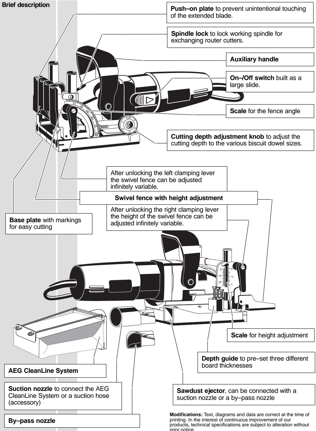
| Chip ejection | Suction hose or angled tube, compatible with Clean Line |
| Bit change | Spindle lock, pin wrench |
| Safety | Fence plate, safety glasses and gloves recommended, automatic stop |
| Maintenance | Clean ventilation slots, use AEG parts |
Frequently Asked Questions - LF 650 AEG
User questions about LF 650 AEG
0 question about this device. Answer the ones you know or ask your own.
Ask a new question about this device
Download the instructions for your Drill in PDF format for free! Find your manual LF 650 - AEG and take your electronic device back in hand. On this page are published all the documents necessary for the use of your device. LF 650 by AEG.
USER MANUAL LF 650 AEG
GB Instructions for use
Please read and save these instructions.
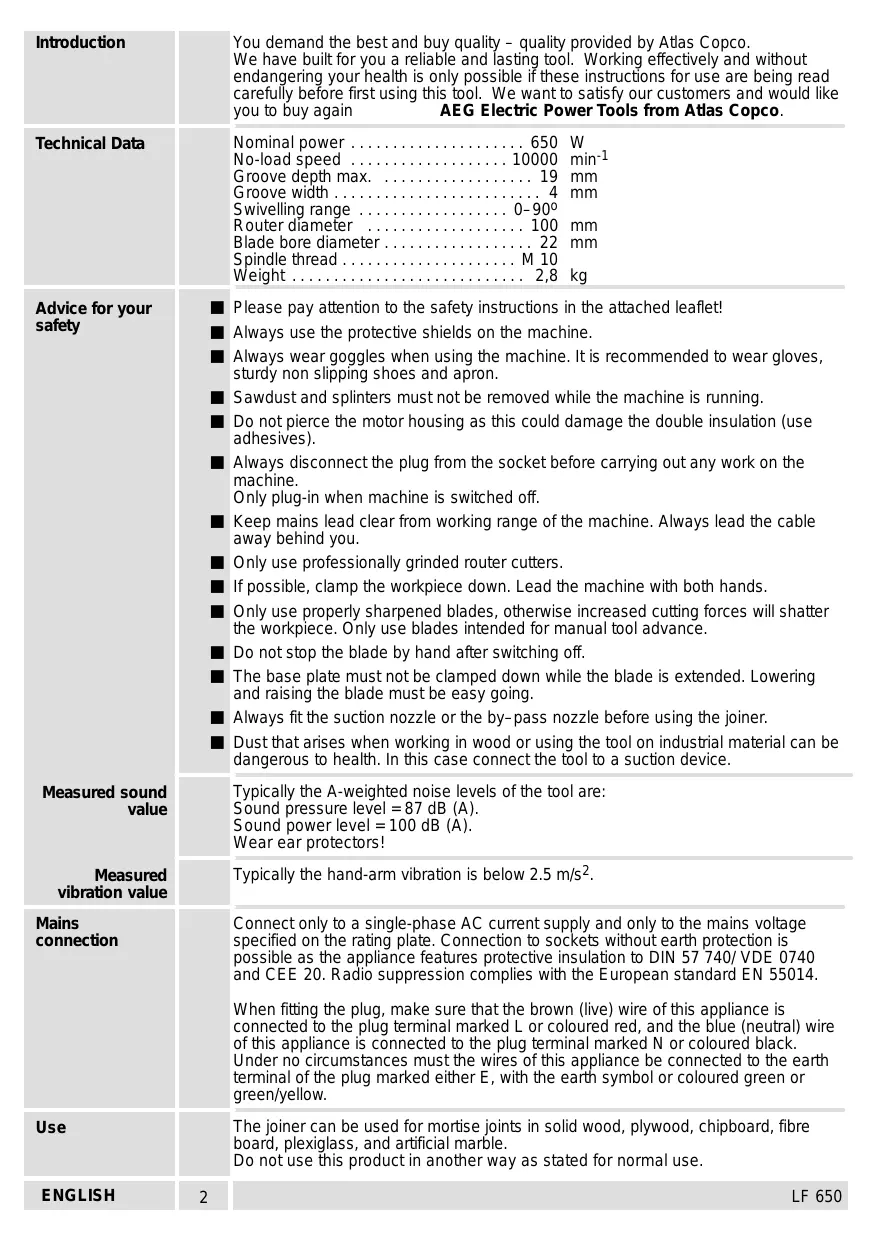
| Introduction | You demand the best and buy quality - quality provided by Atlas Copco. We have built for you a reliable and lasting tool. Working effectively and without endangering your health is only possible if these instructions for use are being read carefully before first using this tool. We want to satisfy our customers and would like you to buy again AEG Electric Power Tools from Atlas Copco. |
| Technical Data | Nominal power 650 W No-load speed 10000 min-1 Groove depth max 19 mm Groove width 4 mm Swivelling range 0-90° Router diameter 100 mm Blade bore diameter 22 mm Spindle thread M 10 Weight 2,8 kg |
| Advice for your safety | Please pay attention to the safety instructions in the attached leaflet! Always use the protective shields on the machine. Always wear goggles when using the machine. It is recommended to wear gloves, sturdy non slipping shoes and apron. Sawdust and splinters must not be removed while the machine is running. Do not pierce the motor housing as this could damage the double insulation (use adhesives). Always disconnect the plug from the socket before carrying out any work on the machine. Only plug-in when machine is switched off. Keep mains lead clear from working range of the machine. Always lead the cable away behind you. Only use professionally grinded router cutters. If possible, clamp the workpiece down. Lead the machine with both hands. Only use properly sharpened blades, otherwise increased cutting forces will shatter the workpiece. Only use blades intended for manual tool advance. Do not stop the blade by hand after switching off. The base plate must not be clamped down while the blade is extended. Lowering and raising the blade must be easy going. Always fit the suction nozzle or the by-pass nozzle before using the joiner. Dust that arises when working in wood or using the tool on industrial material can be dangerous to health. In this case connect the tool to a suction device. |
| Measured sound value | Typically the A-weighted noise levels of the tool are: Sound pressure level = 87 dB (A). Sound power level = 100 dB (A). Wear ear protectors! |
| Measured vibration value | Typically the hand-arm vibration is below 2.5 m/s2. |
| Mains connection | Connect only to a single-phase AC current supply and only to the mains voltage specified on the rating plate. Connection to sockets without earth protection is possible as the appliance features protective insulation to DIN 57 740/ VDE 0740 and CEE 20. Radio suppression complies with the European standard EN 55014. When fitting the plug, make sure that the brown (live) wire of this appliance is connected to the plug terminal marked L or coloured red, and the blue (neutral) wire of this appliance is connected to the plug terminal marked N or coloured black. Under no circumstances must the wires of this appliance be connected to the earth terminal of the plug marked either E, with the earth symbol or coloured green or green/yellow. |
| Use | The joiner can be used for mortise joints in solid wood, plywood, chipboard, fibre board, plexiglass, and artificial marble. Do not use this product in another way as stated for normal use. |
| ENGLISH | 2 LF 650 |
| Choosing the sizes of the biscuit dowels | The size of the biscuit dowels to be used depends on the thickness of the material. Always use biscuit dowels of the biggest possible size to ensure a solid joint. If the working material is thicker than 25 mm, use 2 biscuit dowels on top of each other. | ||
| Thickness of Material | Size of Biscuit Dowel | Measures | |
| 8-12 mm | 0 | 47x15x4 | |
| 12-15 mm | 10 | 53x19x4 | |
| >15 mm | 20 | 56x23x4 | |
| Setting of routing depth | Set the cutting depth with the adjustment knob according to the chosen biscuit dowel to be used. | ||
| Size Biscuit Dowel | Cutting Depth | ||
| No.0 | 0 | 8.0 mm | |
| No.10 | 10 | 10.0 mm | |
| No.20 | 20 | 12.3 mm | |
| Simplex | S | 13.0 mm | |
| Duplex | D | 14.7 mm | |
| maximum | Max | 19.0 mm | |
| Setting the cutting angle | Unlock the left clamping lever, set the swivel fence with aid of the scale to the required angle (e.g. for mitre joints), and re-fasten the clamping lever. The angles most frequently used (22.5°, 45°, 67.5°) can be quickly adjusted with aid of notched stages. | ||
| Should the locked clamping lever be in the way when working with the tool, fasten it in a different position by pulling it out without unlocking it. | |||
| Setting the machine to the thickness of the board | To be able to cut the groove for the biscuit dowel centrically, the joiner must be pre-set to the board thickness. Unlock the right clamping lever, set the swivel fence with aid of the scale to the required board thickness, and re-fasten the clamping lever. The values on the scale are only applicable when the push-on plate is fitted. Should the locked clamping lever be in the way when working with the tool, fasten it in a different position by pulling it out without unlocking it. Three board thicknesses can be pre-set at the depth guide. It is factory pre-set to 16, 19, and 25 mm. | ||
| ENGLISH | 4 | ||
| Marking the groove distances | Place the two boards to be joined on top of each other (flush), fix them with screw-clamps and mark the center of the grooves. The distance between the grooves should be 10-15 cm. Smaller workpieces do not have to be marked. | 10-15 cm 4-6 cm | |
| Depending on the width of the boards the machine can be positioned in different ways. Wide boards: Position the machine to the workpiece such that the base plate middle marking is facing the board marking. Narrow boards: Position the machine with the outer edge of the base plate to the edge of the workpiece. Very narrow boards: Position the machine with the outer marking of the base plate to the edge of the workpiece. This setting can also be used for the case that the biscuit joint is located close to the edge. | |||
| Cutting grooves | 1. Position the machine as described above. 2. Switch the machine on. 3. Push the machine forward and plunge the blade slowly into the material as far as it will go. Hold the machine with both hands. Slightly release the pressure, the motor part is pulled back to the original position by resilience. 4. Switch the machine off. | ||
| ENGLISH | 5 | LF 650 | |
| Joining of workpieces | 1. Apply glue to the grooves. | ||
| 2. Insert a biscuit dowel. | |||
| 3. Put together the workpieces and fix them with clamps, tightening straps, or similar. | |||
| The biscuit dowels well up due to the wetness of the glue, and the joint is additionally strengthened. | |||
| Cutting grooves in thin boards | When cutting thin boards (thickness of material less than 16 mm) a thin piece of wood must be placed under the swivel fence, otherwise the groove is cut too close to the surface of the board. | ||
| Sawdust ejector | The following devices can be connected to the sawdust ejector: suction hose (via suction nozzle 3) AEG CleanLine System (via suction nozzle 3) suction nozzle by-pass nozzle We recommend the AEG NTE 1100 electronic wet-and-dry vacuum cleaner, which has a socket to which this machine can be connected directly. As soon as the saw is switched on, the wet-and-dry vacuum cleaner switches itself on automatically. | ||
| Exchanging the blades | 1. Loosen the four screws and remove the cover plate. | ||
| 2. Depress the spindle lock and remove the flange with aid of a pin-type face spanner. Remove the blade. | |||
| 3. To insert a blade proceed in reverse order. | |||
| When inserting the blade, take care that the arrows on the blade and on the base plate conform. | |||
| ENGLISH | 6 | ||
| On-/off switch | Switching on: Slide back the On/Off switch. To lock, depress the front part of the sliding switch. | 1 2 | |
| Switching off: To unlock, depress the back part of the sliding switch. The switch will automatically move back to "0". | 3 | ||
| Adjusting the cutting depth | After exchanging the blades the cutting depth should be checked and adjusted, if necessary. | ||
| 1. Set the cutting depth adjusting knob to the Max position. | |||
| 2. Push the motor part forward as far as it will go and turn the blade until one tooth has reached the front position. | |||
| 3. Measure the distance from the edge of the base plate to the cutting tooth; it must be 19 mm in the Max position. | |||
| 4. In order to correct the cutting depth, loosen the counter nut and turn the set screw as required. (1 rotation = 0.7 mm) Re-tighten the counter nut. | |||
| Adjusting the angle setting | 1. Set the swivel fence to 0°. | ||
| 2. Loosen the screw ② and move the marking ① until it faces the 0-setting of the swivel fence. Re-tighten the screw. | |||
| Maintenance | The ventilation slots of the machine must be kept clear at all times. Use only AEG accessories and spare parts. Should components need to be replaced which have not been described, please contact one of our AEG service agents (see our list of guarantee/service addresses). If needed, an exploded view of the tool can be ordered. Please state the ten-digit No. as well as the machine type printed on the label and order the drawing at your local service agents or directly at: Atlas Copco Electric Tools GmbH, Postfach 320, D-71361 Winnenden. | ||
| Accessories | The range of accessories with part numbers is shown in our catalogue. | ||
| ENGLISH | 7 | LF 650 | |
EC-DECLARATION OF CONFORMITY
We declare under our sole responsibility that this product is in conformity with the following standards or standardized documents. EN 50144, EN 55104, EN 55014, EN 61000-1, HD 400 in accordance with the regulations 89/392/EEC, 73/23/EEC, 89/336/EEC
DEUTSCH
CE-KONFORMITETSERKL/ERING
D-71361 Winnenden Germany
http://www.atlascopco.de


Brand : AEG
Model : LF 650
Category : Drill