MFM-HT205 - Monitor SONY - Free user manual and instructions
Find the device manual for free MFM-HT205 SONY in PDF.
User questions about MFM-HT205 SONY
0 question about this device. Answer the ones you know or ask your own.
Ask a new question about this device
Download the instructions for your Monitor in PDF format for free! Find your manual MFM-HT205 - SONY and take your electronic device back in hand. On this page are published all the documents necessary for the use of your device. MFM-HT205 by SONY.
USER MANUAL MFM-HT205 SONY
LCD Multi Function Display
MFM-HT205
Owner's Record
The model and serial numbers are located at the rear of the unit. Record these numbers in the spaces provided below. Refer to them whenever you call upon your dealer regarding this product. Model No. ____ Serial No. ____
WARNING
To reduce the risk of fire or electric shock, do not expose this apparatus to rain or moisture.
Dangerously high voltages are present inside the unit. Do not open the cabinet. Refer servicing to qualified personnel only.
FCC Notice
This equipment has been tested and found to comply with the limits for a Class B digital device, pursuant to Part 15 of the FCC Rules. These limits are designed to provide reasonable protection against harmful interference in a residential installation. This equipment generates, uses, and can radiate radio frequency energy and, if not installed and used in accordance with the instructions, may cause harmful interference to radio communications. However, there is no guarantee that interference will not occur in a particular installation. If this equipment does cause harmful interference to radio or television reception, which can be determined by turning the equipment off and on, the user is encouraged to try to correct the interference by one or more of the following measures:
– Reorient or relocate the receiving antenna.
– Increase the separation between the equipment and receiver.
- Connect the equipment into an outlet on a circuit different from that to which the receiver is connected.
- Consult the dealer or an experienced radio/TV technician for help. You are cautioned that any changes or modifications not expressly approved in this manual could void your authority to operate this equipment.
IMPORTANTE
If you have any questions about this product, you may call; Sony Customer Information Services Center 1-800-222-7669 or http://www.sony.com/
Declaration of Conformity
Trade Name: SONY Model: MFM-HT205 Responsible Party: Sony Electronics Inc. Address: 16450 W. Bernardo Dr, San Diego, CA 92127 U.S.A. Telephone Number: 858-942-2230
This device complies with part 15 of the FCC rules. Operation is subject to the following two conditions: (1) This device may not cause harmful interference, and (2) this device must accept any interference received, including interference that may cause undesired operation.
NOTICE
This notice is applicable for USA/Canada only. If shipped to USA/Canada, install only a UL LISTED/CSA LABELLED power supply cord meeting the following specifications:
SPECIFICATIONS
Plug Type Nema-Plug 5-15p Cord Type SVT or SJT, minimum 3 × 18 AWG Length Maximum 15 feet Rating Minimum 7 A, 125 V
NOTICE
natural_image
Technical line drawing of a plug with three leads and a terminal connector (no text or symbols)Important Safety Instructions
1) Read these instructions.
2) Keep these instructions.
3) Heed all warnings.
4) Follow all instructions.
5) Do not use this apparatus near water.
6) Clean only with dry cloth.
7) Do not block any ventilation openings. Install in accordance with the manufacturer's instructions.
8) Do not install near any heat sources such as radiators, heat registers, stoves, or other apparatus (including amplifiers) that produce heat.
9) Do not defeat the safety purpose of the polarized or grounding-type plug. A polarized plug has two blades with one wider than the other. A grounding type plug has two blades and a third grounding prong. The wide blade or the third prong are provided for your safety. If the provided plug does not fit into your outlet, consult an electrician for replacement of the obsolete outlet.
10) Protect the power cord from being walked on or pinched particularly at plugs, convenience receptacles, and the point where they exit from the apparatus.
11) Only use attachments/accessories specified by the manufacturer.
12) Use only with the cart, stand, tripod, bracket, or table specified by the manufacturer, or sold with the apparatus. When a cart is used, use caution when moving the cart/apparatus combination to avoid injury from tip-over.

13) Unplug this apparatus during lightning storms or when unused for long periods of time.
14) Refer all servicing to qualified service personnel. Servicing is required when the apparatus has been damaged in any way, such as power-supply cord or plug is damaged, liquid has been spilled or objects have fallen into the apparatus, the apparatus has been exposed to rain or moisture, does not operate normally, or has been dropped.
Table of Contents
Precautions 5
Identifying parts and controls 6
Setup 9
Setup 1: Use the stand ..... 9
Setup 2: Connect the cables ..... 9
Setup 3: Connect the mains lead ..... 13
Setup 4: Replace the connector cover ..... 13
Setup 5: Turn on the display and other equipment ..... 13
Setup 6: Adjust the tilt ..... 14
Setup 7: Insert batteries into the remote control ..... 14
Watching the TV 15
Setting the TV channels 15
Changing the TV channel 15
Arranging the order of the TV channels ..... 15
Customising the TV channels 16
Using other features 17
Customising Your Display ....18
Navigating the menu 18
Picture menu 19
Selecting the Picture Mode for PC 1/PC 2 ..... 19
Selecting the Picture Mode for TV/COMPONENT/VIDEO 1/ VIDEO 2 ....20
Adjusting "Backlight" 20
Adjusting "Contrast" 20
Adjusting "Brightness" 20
Adjusting "Color" (for TV/COMPONENT/VIDEO 1/VIDEO 2 only) 21
Adjusting “Hue” (for VIDEO 1/VIDEO 2 only) .....21
Adjusting “Sharpness” (for TV/COMPONENT/VIDEO 1/VIDEO 2 only)....21
Adjusting "Color Temp." (for PC 1/PC 2 only) ..... 21
Adjusting “Gamma” (for PC 1/PC 2 only) ..... 22
Resetting Picture Mode to the default 22
Setting "NR" (for TV/COMPONENT/VIDEO 1/ VIDEO 2 only)....22
Setting “Dynamic Contrast” (for TV/COMPONENT/VIDEO 1/VIDEO 2 only) 22
Audio menu 23
Setting "Surround" 23
Adjusting “Treble,” “Bass,” and “Balance” 24
Setting "Auto Volume" (for TV/COMPONENT/VIDEO 1/VIDEO 2 only) 24
Setting "Dual Sound" (for TV/COMPONENT/VIDEO 1/VIDEO 2 only) 24
Resetting all audio settings to the default .....24
• Macintosh is a trademark licensed to Apple Computer, Inc., registered in the U.S.A. and other countries.
- Windows ^® is registered trademark of Microsoft Corporation in the United States and other countries.
• VGA is registered trademarks of IBM Corporation of the U.S.A.
- VESA and DDC ^TM are trademarks of the Video Electronics Standards Association.
- Adobe and Acrobat are trademarks of Adobe Systems Incorporated.
- WOW, SRS and (●) symbol are trademarks of SRS Labs, Inc.
- WOW technology is incorporated under license from SRS Labs, Inc.
- All other product names mentioned herein may be the trademarks or registered trademarks of their respective companies.
- Furthermore, “TM” and “®” are not mentioned in each case in this manual.
Screen menu 25
Setting "Zoom" 25
Automatic picture quality adjustment function (for PC 2 only) 25
Making further automatic adjustments to the picture quality for the current input signal (Auto Adjust) (for PC 2 only) ..... 25
Adjusting the picture's sharpness manually (Phase/Pitch) (for PC 2 only) 26
Adjusting the picture's position manually (H Center /V Center) (for PC 2 only) 26
Adjusting the picture's position manually (V Center) (for TV/COMPONENT/VIDEO 1/VIDEO 2 only) ..... 27
Changing the display resolution (Resolution) (for PC 2 only) 27
Option menu 27
Setting “PIP” (Picture In Picture) or “PAP” (Picture And Picture) (for PC 1/PC 2 only) 27
Setting "TeleText" (for TV/VIDEO 1/VIDEO 2 only) ..... 29
Setting "Input Sensing" (for PC 1/PC 2 only) 29
Setting "Language" 29
Setting "Menu Position" 30
Setting "Menu Lock" 30
Setting "Demo Mode" 30
Resetting to the default setting 30
Technical Features ....31
Controlling the volume 31
Power saving function 31
Setting the Picture Mode 32
Automatic brightness adjustment function (light sensor) ..... 32
Automatic picture quality adjustment function (for PC 2 only) ... 32
Turning off the display automatically (for TV/COMPONENT/VIDEO 1/VIDEO 2 only) 33
Using the TeleText service (for TV/VIDEO 1/VIDEO 2 only) .... 33
Troubleshooting ....34
On-screen messages 34
Trouble symptoms and remedies 35
Specifications 38
Precautions
Warning on power connections
- Use the supplied mains lead. If you use a different mains lead, be sure that it is compatible with your local power supply.
For the customers in the U.S.A.
If you do not use the appropriate cord, this display will not conform to mandatory FCC standards.
For the customers in the UK
If you use the display in the UK, be sure to use the appropriate UK mains lead.
Example of plug types
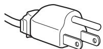
for 100 to 120 V AC

for 200 to 240 V AC
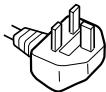
for 240 V AC only
The equipment should be installed near an easily accessible mains.
Installation
Do not install or leave the display:
- In places subject to extreme temperatures, for example near a radiator, heating vent, or in direct sunlight. Subjecting the display to extreme temperatures, such as in an automobile parked in direct sunlight or near a heating vent, could cause deformations of the casing or malfunctions.
- In places subject to mechanical vibration or shock.
- The ventilation should not be impeded by covering the ventilation openings with items, such as newspapers, tablecloths, curtains, etc.
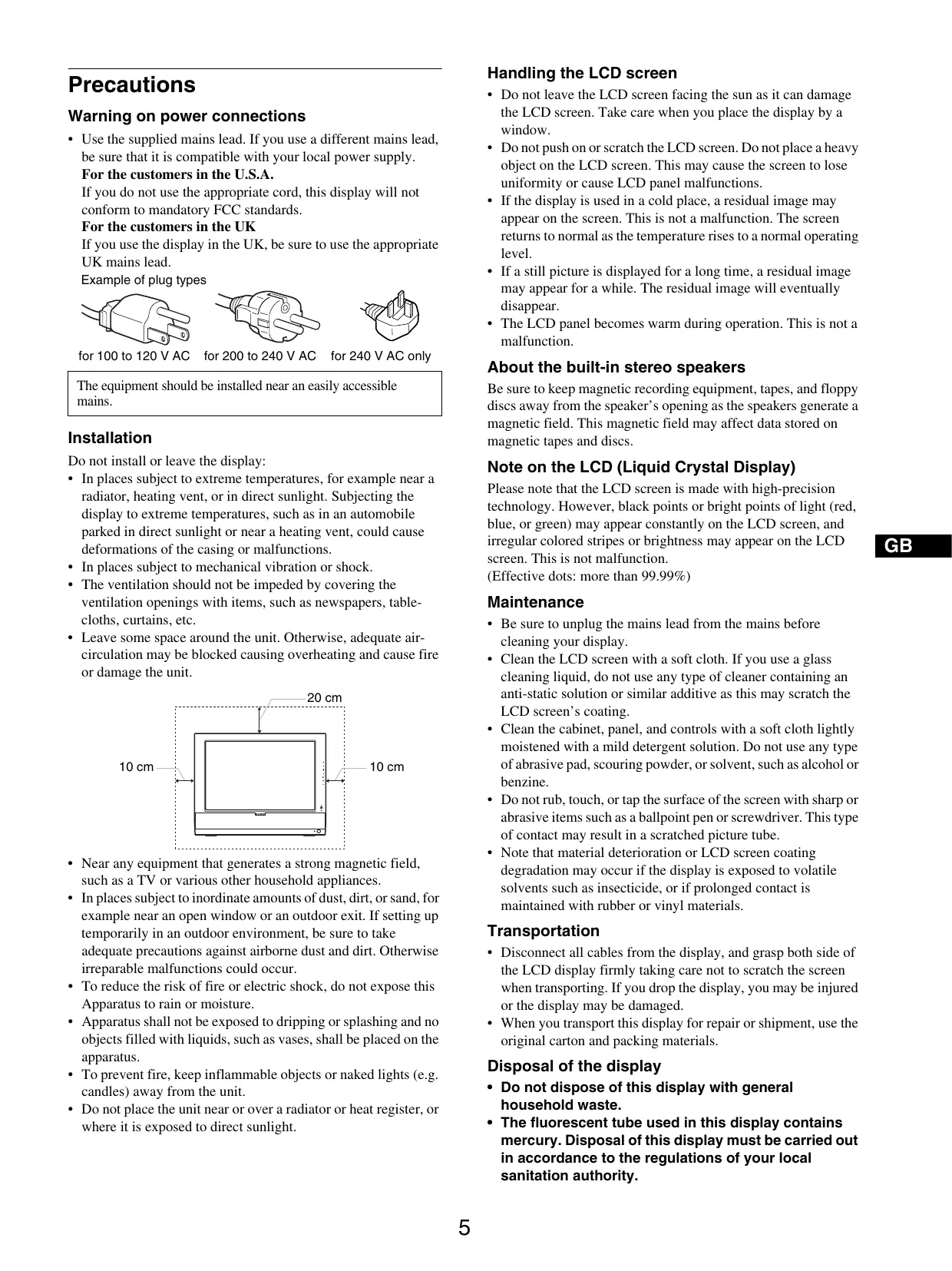
- Leave some space around the unit. Otherwise, adequate air-circulation may be blocked causing overheating and cause fire or damage the unit.
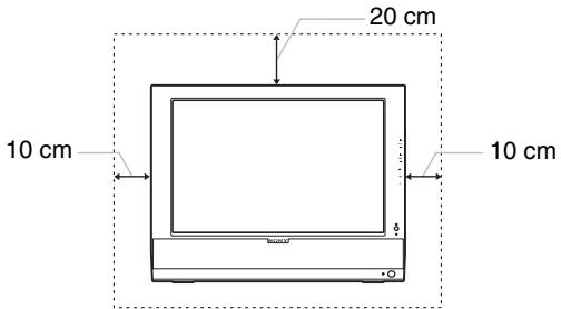
text_image
20 cm 10 cm 10 cm- Near any equipment that generates a strong magnetic field, such as a TV or various other household appliances.
- In places subject to inordinate amounts of dust, dirt, or sand, for example near an open window or an outdoor exit. If setting up temporarily in an outdoor environment, be sure to take adequate precautions against airborne dust and dirt. Otherwise irreparable malfunctions could occur.
- To reduce the risk of fire or electric shock, do not expose this Apparatus to rain or moisture.
- Apparatus shall not be exposed to dripping or splashing and no objects filled with liquids, such as vases, shall be placed on the apparatus.
- To prevent fire, keep inflammable objects or naked lights (e.g. candles) away from the unit.
- Do not place the unit near or over a radiator or heat register, or where it is exposed to direct sunlight.
Handling the LCD screen
- Do not leave the LCD screen facing the sun as it can damage the LCD screen. Take care when you place the display by a window.
- Do not push on or scratch the LCD screen. Do not place a heavy object on the LCD screen. This may cause the screen to lose uniformity or cause LCD panel malfunctions.
- If the display is used in a cold place, a residual image may appear on the screen. This is not a malfunction. The screen returns to normal as the temperature rises to a normal operating level.
- If a still picture is displayed for a long time, a residual image may appear for a while. The residual image will eventually disappear.
- The LCD panel becomes warm during operation. This is not a malfunction.
About the built-in stereo speakers
Be sure to keep magnetic recording equipment, tapes, and floppy discs away from the speaker's opening as the speakers generate a magnetic field. This magnetic field may affect data stored on magnetic tapes and discs.
Note on the LCD (Liquid Crystal Display)
Please note that the LCD screen is made with high-precision technology. However, black points or bright points of light (red, blue, or green) may appear constantly on the LCD screen, and irregular colored stripes or brightness may appear on the LCD screen. This is not malfunction.
(Effective dots: more than 99.99%)
Maintenance
- Be sure to unplug the mains lead from the mains before cleaning your display.
- Clean the LCD screen with a soft cloth. If you use a glass cleaning liquid, do not use any type of cleaner containing an anti-static solution or similar additive as this may scratch the LCD screen's coating.
- Clean the cabinet, panel, and controls with a soft cloth lightly moistened with a mild detergent solution. Do not use any type of abrasive pad, scouring powder, or solvent, such as alcohol or benzine.
- Do not rub, touch, or tap the surface of the screen with sharp or abrasive items such as a ballpoint pen or screwdriver. This type of contact may result in a scratched picture tube.
- Note that material deterioration or LCD screen coating degradation may occur if the display is exposed to volatile solvents such as insecticide, or if prolonged contact is maintained with rubber or vinyl materials.
Transportation
- Disconnect all cables from the display, and grasp both side of the LCD display firmly taking care not to scratch the screen when transporting. If you drop the display, you may be injured or the display may be damaged.
- When you transport this display for repair or shipment, use the original carton and packing materials.
Disposal of the display
- Do not dispose of this display with general household waste.
- The fluorescent tube used in this display contains mercury. Disposal of this display must be carried out in accordance to the regulations of your local sanitation authority.
Disposal of used batteries
To preserve our environment, dispose the used batteries according to your local laws or regulations.
Installation on a wall or a mounting arm
If you intend to install the display on a wall or a mounting arm, be sure to consult qualified personnel.
Identifying parts and controls
See the pages in parentheses for further details.
Front of the LCD display
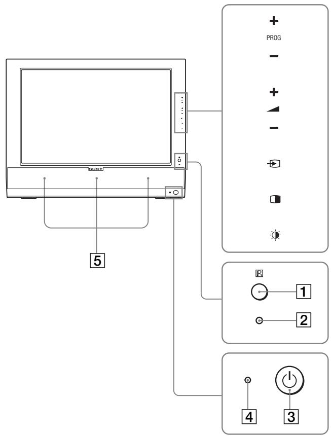
text_image
BONY 5 + PROG - + - + - 1 2 4 3Side view of the LCD display
text_image
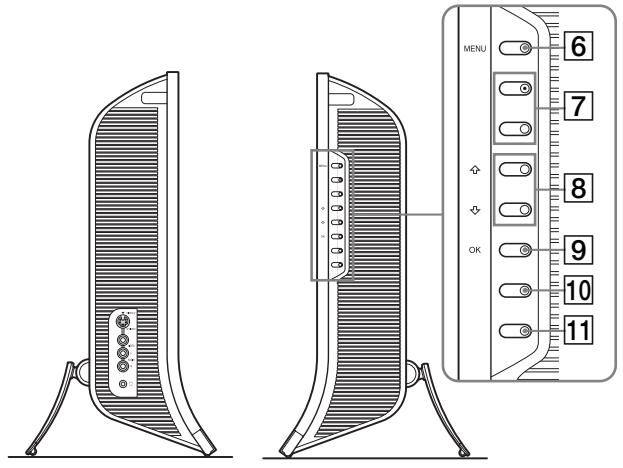
MENU 6 7 8 9 10 11Rear of the LCD display
text_image
13 121 Remote control sensor
This sensor receives a signal from the remote control. Be sure not to cover the sensor with papers, etc.
2 Light sensor (page 32)
This sensor measures the brightness of the surrounding area. Be sure not to cover the sensor with papers, etc.
3 ⏻ (power) switch (page 13)
Press to turn the display on or off.
4 ⏻ (power) indicator (pages 13, 31)
The power indicator lights up in green when the display is turned on, and lights up in orange when the display is in the power saving mode. Also, the power indicator lights up in red when the display is in the standby mode or the Sleep timer is activated.
5 Stereo speakers (page 31)
These speakers output the audio signals as sound.
6 MENU button (page 18)
Press to turn the menu screen on and off.
7 PROG+/- buttons (page 15)
Press to change the TV channel.
8 ↑/↓ and ▲+/- (volume control) buttons (pages 18, 31)
Use to select the menu items and to make adjustments, and also display the “Volume” adjustment bar to control the volume.
9 → (input select)/OK button (page 13, 18)
This button functions in two ways.
As the ⬤ button, this button switches the input signal between PC 1, PC 2, TV, COMPONENT, VIDEO 1, and VIDEO 2 when two computers and two pieces of video equipment are connected.
As the OK button, this button activates the selected menu item or adjustments made using the ↑/↓ buttons 8.
10 (PIP/PAP) button (page 27)
Press to switch the “PIP” (Picture In Picture) or “PAP” (Picture And Picture) setting. Each time you press this button, the PIP or PAP setting changes as follows.
$$ \mathrm{PIPOn} \rightarrow \mathrm{PAPOn} \rightarrow \mathrm{Off} \rightarrow \mathrm{PIPOn} \dots $$
11 ⚙ (Picture Mode) button (page 32)
Press to switch the Picture Mode.
12 Connector cover (page 9)
Remove this cover when you connect cables or cords.
13 Screw positions of VESA compatible mounting arm or stand (page 9)
Attach the VESA compatible mounting arm or stand.
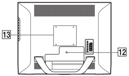
Rear of the LCD display
text_image
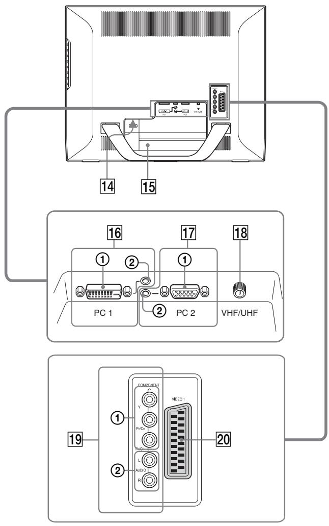
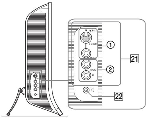
14 15 16 17 18 PC 1 PC 2 VHF/UHF COMPONENT Y Pv/C Video I L A/DI R 20 19Side view of the LCD display
text_image
VIDEO 2 S VIDEO AUDIO L AUDIO R ① ② 21 ②214 AC IN connector (page 13)
This connector connects the mains lead (supplied).
15 Security Lock Hole
The security lock hole should be used with the Kensington Micro Saver Security System.
Micro Saver Security System is a trademark of Kensington.
16 PC 1 connectors
① DVI-D input connector (digital RGB) for PC 1 (page 10)
This connector inputs digital RGB video signals that comply with DVI Rev.1.0.
② Audio input jack for PC 1 (page 10)
This jack inputs audio signals when connected to the audio output jack of a computer or other equipment connected to PC 1.
17 PC 2 connectors
① HD15 input connector (analog RGB) for PC 2 (page 10)
This connector inputs analog RGB video signals (0.700 Vp-p, positive) and sync signals.
② Audio input jack for PC 2 (page 10)
This jack inputs audio signals when connected to the audio output jack of a computer or other equipment connected to PC 2.
18 VHF/UHF jack (page 12)
This jack inputs a signal from an aerial.
19 COMPONENT jacks
① Y/P B /P R Component Video input jacks for COMPONENT (page 11)
These jacks input Y/P_B/P_R Component Video signals (Y/ C_B/C_R , Y/B-Y/R-Y, or Y/P_B/P_R ).
② Audio input jacks for COMPONENT (page 11)
These jacks input audio signals when connected to the audio output jacks of a DVD player or other equipment connected to COMPONENT.
20 VIDEO 1 (Scart) jack (page 11)
This jack inputs analog RGB video signals or composite video signals.
This jack has an output function for TV signals.
21 VIDEO 2 jacks
① Composite/S video input jacks for VIDEO 2 (page 12)
These jacks input composite video or S video signals. When you connect video equipment to both composite video input and S video input jacks, the signal from the S video jack is displayed.
② Audio input jacks for VIDEO 2 (page 12)
These jacks input audio signals when connected to the audio output jacks of a VCR or other equipment connected to VIDEO 2.
22 Headphones jack (page 31)
This jack outputs audio signals to the headphones.
Remote control
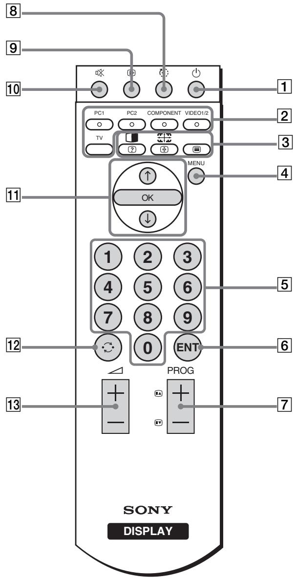
text_image
8 9 10 PC1 PC2 COMPONENT VIDEO1/2 TV ? MENU 4 11 OK ↓ 1 2 3 4 5 6 7 8 9 12 0 ENT PROG 13 7 SONY DISPLAY1 ⏻ (power) switch (page 13)
Press to turn the display on or off.
2 Input select buttons
PC 1 (page 10): Press to select a signal input through the PC 1 connectors (DVI-D) on the rear. In the TeleText mode, press to select red option.
PC 2 (page 10): Press to select a signal input through the PC 2 connectors (HD15) on the rear. In the TeleText mode, press to select green option.
COMPONENT (page 11):
Press to select a signal input through the COMPONENT jacks (Y/P B /P R Component) on the rear.
In the TeleText mode, press to select yellow option.
VIDEO 1/2 (page 11):
Press to select a signal input through the VIDEO 1 (Scart) jack (analog RGB/ composite video) on the rear and the VIDEO 2 jacks (composite/S video) on the side of the display. In the TeleText mode, press to select blue option.
TV (page 15): Press to select the TV input.
3 Feature buttons
(PIP/PAP)/ ? (reveal/conceal) (page 27):
Press repeatedly to step through the “PIP” or “PAP” settings.
In the TeleText mode, press to reveal concealed information. Press it again to conceal the information.
(Zoom)/ (page hold) (page 25):
Press repeatedly to step through the “Zoom” settings.
In the TeleText mode, press to freeze a sub page which follows on automatically. Press it again to cancel the freeze.
☐ (TeleText) (page 33):
Press to turn on or off the TeleText mode.
4 MENU button (page 18)
Press to turn the menu screen on and off.
5 0-9 buttons (page 15)
Use these buttons to input numbers.
6 ENT (enter) button (page 15)
Press to confirm the numbers you input using the 0-9 buttons.
7 PROG +/- (≡ (page advance)/ ≡ (page reverse)) buttons (page 15)
Press to change the TV channel.
In the TeleText mode, press to access the next or preceding page.
8 (sleep) button (page 33)
Press repeatedly to set the display to turn off automatically after a specified period of time. If you use this function and set the Sleep timer, the ⏻ (power) indicator lights up in red.
9 i+ (display) button (page 17)
Press once to display the current channel number or the current input. They will remain until you press this button again.
10 ✉ (muting) button (page 17)
Press to turn the sound off. Press again or press the + button to restore the sound.
11 ↑/↓ and OK buttons (page 18)
Use the ↑/↓ buttons to select menu items and make adjustments.
Press the OK button to activate the selected menu item and adjustments made using the ↑/↓ buttons.
12 ↻ (jump) button (page 17)
Press to switch the TV channel between the current one and the last one that was selected using the 0-9 buttons.
13 △ +/- buttons (page 31)
Press to adjust the sound volume.
Setup
Before using your display, check that the following items are included in your carton:
- LCD display
- Remote control
• Size AAA batteries (2) - Mains lead
• HD15-HD15 video signal cable (analog RGB)
• DVI-D video signal cable (digital RGB)
• Audio cord (stereo miniplug) - 75-ohm coaxial cable
- CD-ROM (utility software for Windows/Macintosh, Operating Instructions, etc.)
- Warranty card
- Quick Setup Guide
Setup 1: Use the stand
■ Using the supplied stand
Open the stand.
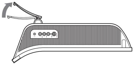
natural_image
Technical line drawing of a mechanical component with a lever and mounting bracket (no text or symbols)Note
The stand is folded at the factory. Be sure not to place the display vertically with the stand as it is. Otherwise, the display may topple over.
■ Using the VESA compatible stand
When using a non-supplied VESA compatible mounting arm or stand, use the VESA compatible screws to attach.
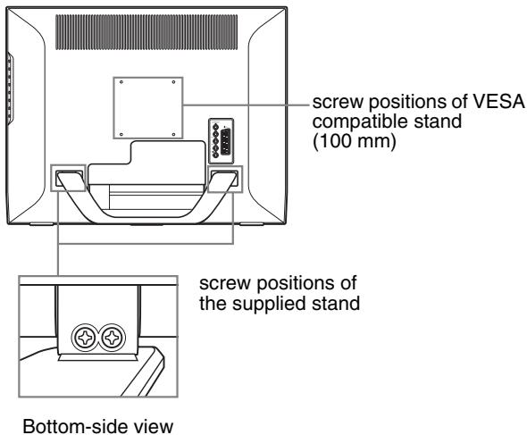
text_image
screw positions of VESA compatible stand (100 mm) screw positions of the supplied stand Bottom-side viewYou can use the display with or without the supplied stand.
Setup 2: Connect the cables
- Turn off the display, computer, and other equipment before connecting them.
• If you intend to connect: - A computer equipped with an HD15 output connector (analog RGB) → See “Connecting a computer using the PC 2 connectors” (page 10).
- Video equipment that has component video output jacks or a Scart connector
→ See “Connecting video equipment using the COMPONENT jacks” (page 11). - Video equipment that has analog RGB/composite video output jacks or a Scart connector
→ See “Connecting video equipment using the VIDEO 1 (Scart) jack” (page 11). - Video equipment that has composite/S video output jacks or a Scart connector
→ See “Connecting video equipment using the VIDEO 2 jacks” (page 12). - An aerial
→ See “Connecting an aerial” (page 12).
Notes
- Do not touch the pins of the video signal cable connector as this might bend the pins.
- Be sure that the cables connected to the display does not get pinched under the stand.
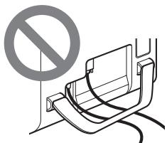
text_image
Diagram showing a no-smoking sign above a vehicle seat with cable, indicating restricted parking or usage.Remove the connector cover.
Push the hooks and draw the connector cover towards you.
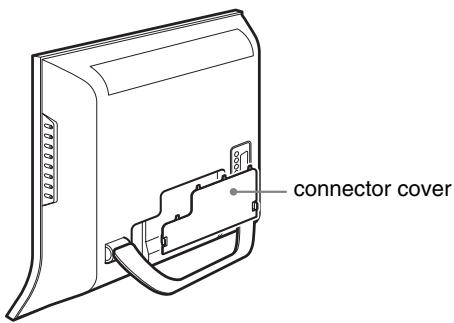
text_image
connector cover■ Connecting a computer using the PC 1 connectors
If you intend to connect a computer equipped with a DVI connector (digital RGB), follow the instructions below. Using the supplied DVI-D video signal cable (digital RGB) and the supplied audio cord, connect the computer to the display's PC 1 connectors.
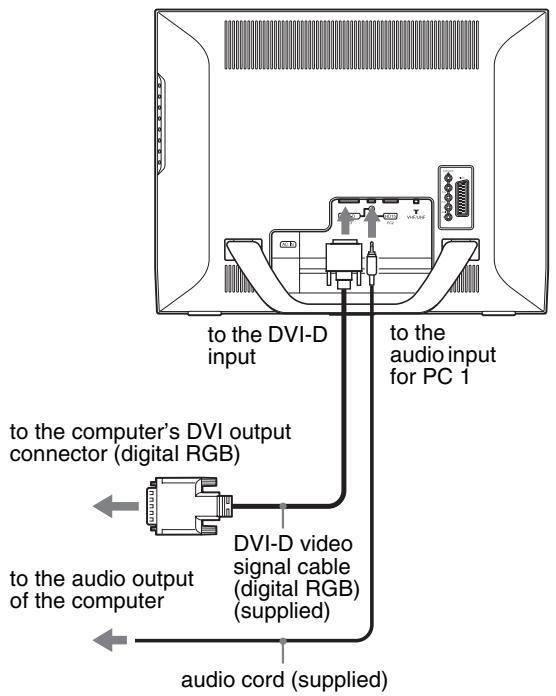
text_image
to the DVI-D input to the audio input for PC 1 to the computer's DVI output connector (digital RGB) DVI-D video signal cable (digital RGB) (supplied) to the audio output of the computer audio cord (supplied)■ Connecting a computer using the PC 2 connectors
If you intend to connect a computer equipped with an HD15 connector (analog RGB), follow the instructions below. Using the supplied HD15-HD15 video signal cable (analog RGB) and the supplied audio cord, connect the computer to the display's PC 2 connectors.
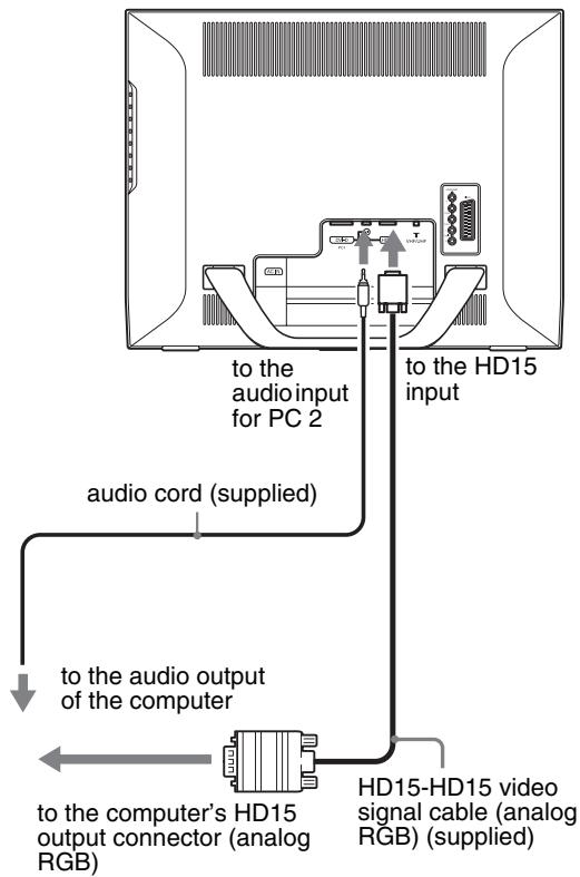
text_image
to the audio input for PC 2 to the HD15 input audio cord (supplied) to the audio output of the computer to the computer's HD15 output connector (analog RGB) HD15-HD15 video signal cable (analog RGB) (supplied)■ Connecting video equipment using the COMPONENT jacks
If you intend to connect video equipment that has component video output jacks, such as a DVD player, follow the instructions below.
Using a video signal cable (not supplied) and an audio cord (not supplied), connect the video equipment to the display's COMPONENT jacks.
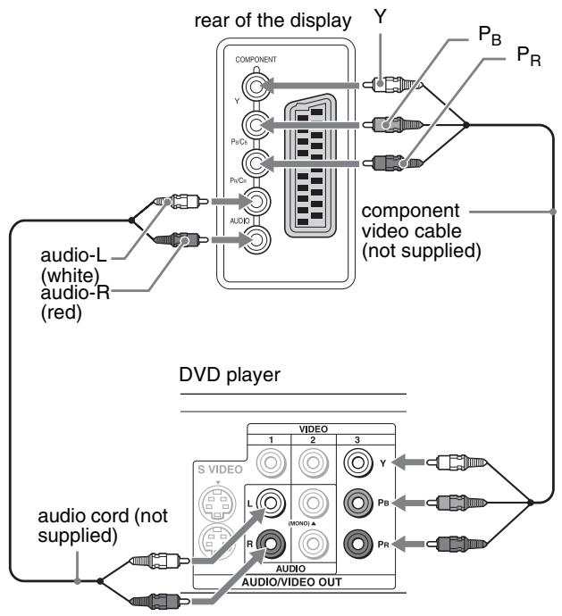
flowchart
graph TD
    A["rear of the display"] --> B["COMPONENT"]
    B --> C["Y"]
    B --> D["P_B"]
    B --> E["P_R"]
    B --> F["AUDIO"]
    G["audio-L (white) audio-R (red)"] --> H["Component video cable (not supplied)"]
    I["audio cord (not supplied)"] --> J["DVD player"]
    K["VIDEO"] --> L["1"]
    K --> M["2"]
    K --> N["3"]
    O["S VIDEO"] --> P["L"]
    O --> Q["R"]
    R["PR"] --> S["MODO"]
    T["PB"] --> U["1"]
    V["PR"] --> W["2"]
    X["PR"] --> Y["3"]
If you intend to connect video equipment that has a Scart connector, such as a DVD player, follow the instructions below. Using a Scart adapter cable (not supplied) and an audio cord (not supplied), connect the video equipment to the display's COMPONENT jacks.
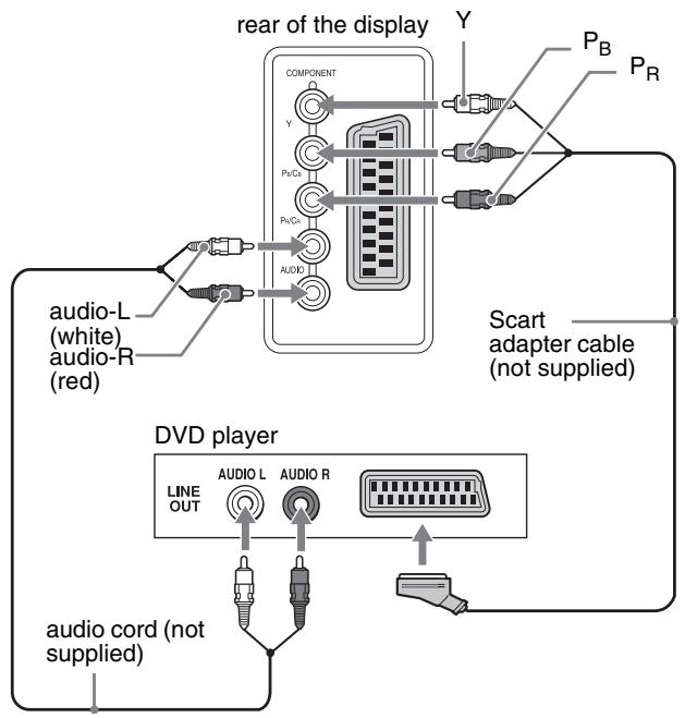
flowchart
graph TD
    A["rear of the display"] --> B["COMPONENT"]
    B --> C["Y"]
    B --> D["PuD+"]
    B --> E["PuC+"]
    B --> F["AUDIO"]
    G["Scart adapter cable (not supplied)"] --> H["Line OUT"]
    G --> I["AUDIO L"]
    G --> J["AUDIO R"]
    K["audio-L (white) audio-R (red)"] --> L["Audio"]
    M["audio cord (not supplied)"] --> N["Audio"]
■ Connecting video equipment using the VIDEO 1 (Scart) jack
If you intend to connect video equipment that has analog RGB/ composite video output jacks, such as a VCR, follow the instructions below.
Using a Scart adapter cable (not supplied), connect the video equipment to the display's VIDEO 1 (Scart) jack.
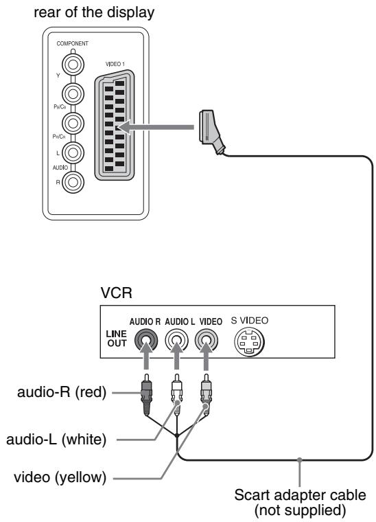
text_image
rear of the display COMPONENT Y VIDEO 1 Px/Cx Px/Cx L AUDIO R VCR LINE OUT AUDIO R AUDIO L VIDEO S VIDEO audio-R (red) audio-L (white) video (yellow) Scart adapter cable (not supplied)If you intend to connect video equipment that has a Scart connector, such as a VCR, follow the instructions below.
Using a Scart adapter cable (not supplied), connect the video equipment to the display's VIDEO 1 (Scart) jack.
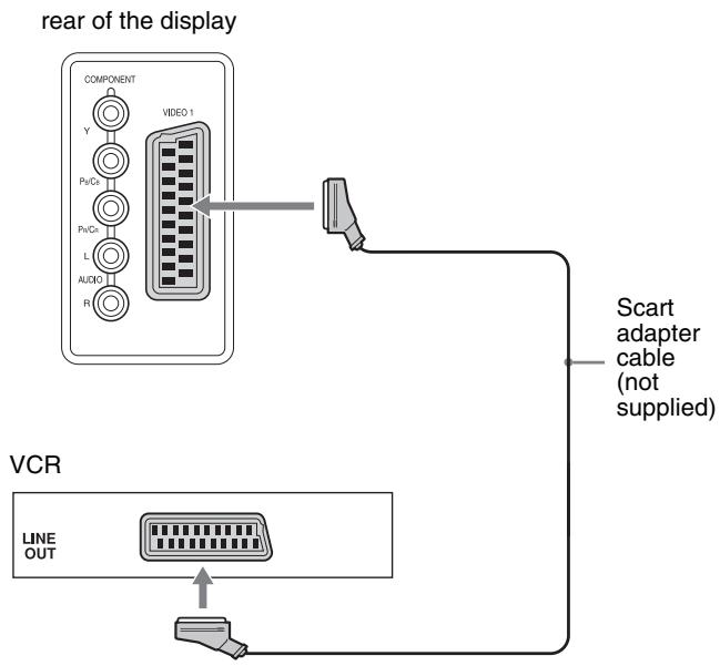
flowchart
graph TD
    A["rear of the display"] --> B["COMPONENT"]
    B --> C["VIDEO 1"]
    C --> D["Scart adapter cable (not supplied)"]
    D --> E["VCR"]
    E --> F["LINE OUT"]
    F --> G["Output"]
By this connection, you can view both analog RGB video signals and composite video signals output from video equipment. Also, you can output TV signals and record the signals on the video equipment connected to the display.
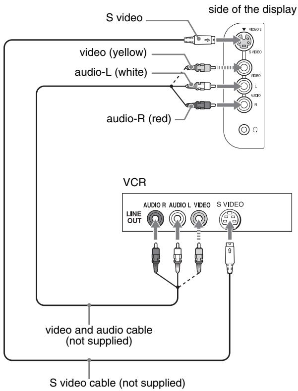
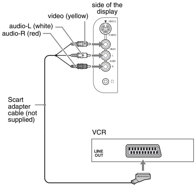
■ Connecting video equipment using the VIDEO 2 jacks
If you intend to connect video equipment that has composite/S video output jacks, such as a VCR, follow the instructions below. Using a video signal cable (not supplied) and an audio cord (not supplied), connect the video equipment to the display's VIDEO 2 jacks.
flowchart
graph TD
    A["S video"] --> B["video (yellow)"]
    A --> C["audio-L (white)"]
    A --> D["audio-R (red)"]
    B --> E["VCR"]
    C --> E
    D --> E
    E --> F["AUDIO R"]
    E --> G["AUDIO L"]
    E --> H["S VIDEO"]
    F --> I["LINE OUT"]
    G --> J["Line OUT"]
    H --> K["Line OUT"]
    L["side of the display"] --> M["VIDEO 2"]
    L --> N["VIDEO L"]
    L --> O["AUDIO R"]
    L --> P["Ω"]
    Q["video and audio cable (not supplied)"] --> R["S video cable (not supplied)"]
Note When you connect video equipment to both composite video input and S video input jacks, the signal from the S video jack is displayed.
If you intend to connect video equipment that has a Scart connector, such as a VCR, follow the instructions below.
Using a Scart adapter cable (not supplied), connect the video equipment to the display's VIDEO 2 jacks.
flowchart
graph TD
    A["video (yellow)"] --> B["video-L (white)"]
    A --> C["video-R (red)"]
    D["side of the display"] --> E["VIDEO 2"]
    D --> F["VIDEO"]
    D --> G["L"]
    D --> H["AUDIO"]
    D --> I["R"]
    J["Scart adapter cable (not supplied)"] --> K["VCR"]
    L["LINE OUT"] --> M["Output"]
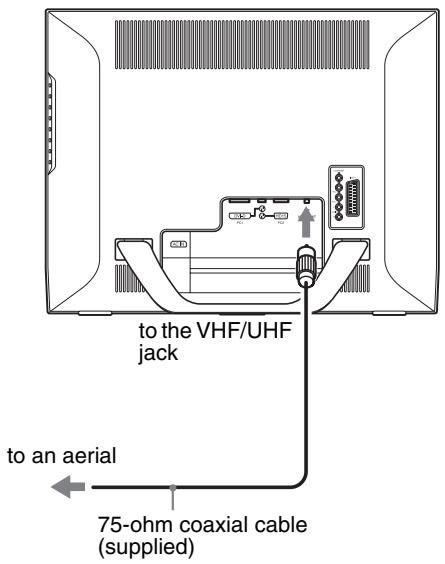
■ Connecting an aerial
If you intend to connect an aerial to receive the TV signal, follow the instructions below.
Using the 75-ohm coaxial cable (supplied), connect an aerial to the display's VHF/UHF jack.
text_image
to the VHF/UHF jack to an aerial 75-ohm coaxial cable (supplied)Note
It is strongly recommended that you connect the aerial using a 75-ohm coaxial cable to get optimum picture quality. A 300-ohm twin lead cable can be easily affected by radio noise and the like, resulting in signal deterioration. If you use a 300-ohm twin lead cable, keep it away as far as possible from the display.
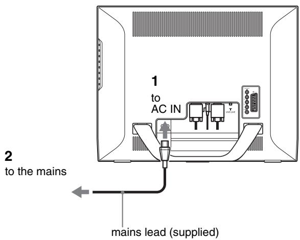
Setup 3: Connect the mains lead
1 Connect the supplied mains lead securely to the display's AC IN connector.
2 Connect the other end securely to the mains.
text_image
1 to AC IN 2 to the mains mains lead (supplied)Setup 4: Replace the connector cover
While pressing the hooks, push the connector cover onto the display until it clicks.

text_image
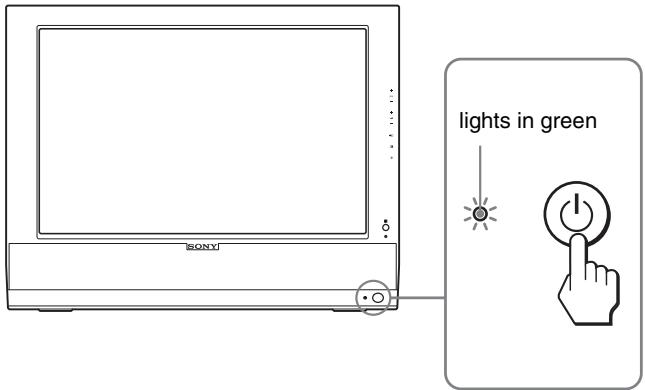
connector coverSetup 5: Turn on the display and other equipment
1 Press the ⏻ (power) switch on the front of the display.
The ⏻ (power) indicator lights up in green.
text_image
lights in green SONY2 Turn on the computer or other video equipment.
3 Press the ➕ button to select the desired input signal.
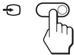
The input signal will change each time you press the ➕ button.
| On-screen message | Input signal configuration |
| DVI-D: PC 1 | DVI-D input connector (digital RGB) for PC 1 |
| HD15: PC 2 | HD15 input connector (analog RGB) for PC 2 |
| TV channels | TV |
| →: COMPONENT | Y/P_B/P_R Component Video input jacks for COMPONENT |
| →or→: VIDEO 1 | Analog RGB/composite video input jack for VIDEO 1Constant TV signal output |
| →or→: VIDEO 2 | Composite/S video input jacks for VIDEO 2 |
Tips
- You can also select the inputs using the input select buttons on the remote control.
- When you select the TV input, the number of the selected channel is displayed in the upper right corner of the screen.
- When using the PIP or PAP function, use “PIP/PAP” in the “PIP/PAP” menu in the “Option” menu to select the input source for sub picture (page 27). If the TV input is selected for sub picture, you can change the channel using the PROG +/- buttons.
- When you switch the TV channel while listening or operate your PC, video or decoding device, switch the input to TV, then press PROG +/- or 0-9 buttons. If you press PROG +/- or 0-9 buttons, the input cannot be automatically switched to TV.
If no picture appears on the screen
- Check that the mains lead and the video signal cable are properly connected.
- If “No Input Signal” appears on the screen:
- The computer is in the power saving mode. Try pressing any key on the keyboard or moving the mouse.
- Check that the input signal setting is correct by pressing the ➕ button (page 13).
- If “Cable Disconnected” appears on the screen:
- Check that the video signal cable is properly connected.
- Check that the input signal setting is correct by pressing the ➕ button (page 13).
- If “Out Of Range” appears on the screen, reconnect the old display. Then adjust the computer’s graphics board within the following ranges.
| Analog RGB | Digital RGB | |
| Horizontal frequency | 28–86 kHz | 28–68 kHz |
| Vertical frequency | 48–85 Hz (resolution < 1,280 × 1,024)48–75 Hz (resolution < 1,400 × 1,050)48–60 Hz (resolution ≤ 1,680 × 1,050) | 60 Hz |
| Resolution | 1,680 × 1,050 or less | 1,680 × 1,050 or less |
For more information about on-screen messages, see “Trouble symptoms and remedies” on page 35.
No need for specific drivers
The display complies with the “DDC” Plug & Play standard and automatically detects all the display’s information. No specific driver needs to be installed on the computer.
The first time you turn on your computer after connecting the display, the setup Wizard may appear on the screen. In this case, follow the on-screen instructions. The Plug & Play display is automatically selected so that you can use this display.
The vertical frequency is set to 60 Hz.
Since flickers are unobtrusive on the display, you can use it as it is. You do not need to set the vertical frequency to any particular high value.
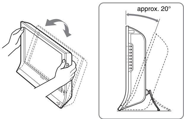
Setup 6: Adjust the tilt
This display can be adjusted within the angles shown below.
Grasp the sides of the LCD panel, then adjust the screen angles.
text_image
approx. 20°To use the display comfortably
Adjust the viewing angle of your display according to the height of your desk and chair so that light is not reflected from the screen to your eyes.
Notes
- When adjusting the screen tilt, proceed slowly and carefully, being sure not to hit the display against the desk.
- When adjusting the screen tilt, make sure not to knock or drop the display off the desk.
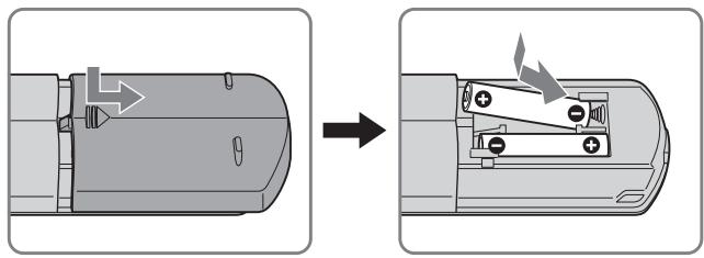
Setup 7: Insert batteries into the remote control
Insert two size AAA batteries (supplied) by matching the + and – marks on the batteries to the diagram inside the remote control's battery compartment.
natural_image
Diagram showing a device being processed from an external component, with no visible text or symbols.Notes
- Remove the batteries to avoid damage from possible battery leakage whenever you anticipate that the remote control will not be used for an extended period.
- Handle the remote control with care. Avoid dropping it, getting it wet, or placing it in direct sunlight, near a heater or where the humidity is high.
Watching the TV

Setting the TV channels
To watch TV programs, you need to set up your channels.
Perform the following procedure before you watch TV programs for the first time.
For details on the use of the menu and buttons, see “Navigating the menu” on page 18.
Message of “Please Start Auto Tuning” appears until you select “Auto Tuning.”
1 Press the MENU button.
2 Press the ↑/↓ buttons to select 📋 (Set Up) and press the OK button.
The “Set Up” menu appears on the screen.
3 Press the ↑/↓ buttons to select "Auto Tuning" and press the OK button.
The “Auto Tuning” menu appears on the screen.
4 Press the ↑/↓ buttons to select "OK" and press the OK button.
The display starts scanning and preparing channels automatically.
Channel number and on-screen message appear.
5 Press the MENU button to exit the menu screen after "Auto Tuning" is completed.
Note
This procedure may take some minutes. Do not press any buttons during the process. Otherwise, “Auto Tuning” will not be completed properly.
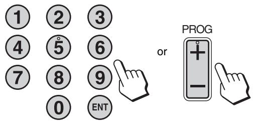
Changing the TV channel
Press the 0-9 buttons to input a channel number.
The channel changes after 3 seconds. Press the ENT (enter) button to select immediately.
Use the PROG +/- buttons to scan through the channels.
text_image
1 2 3 4 5 6 7 8 9 0 ENT or PROGTips
- When you press and hold the PROG + or – button, the channel number will change rapidly.
- When you switch the TV channel while listening or operate your PC, video or decoding device, switch the input to TV, then press PROG +/- or 0-9 buttons. If you press PROG +/- or 0-9 buttons, the input cannot be automatically switched to TV.
Arranging the order of the TV channels
You can arrange the order of the TV channel to suit your preference.
1 Press the MENU button.
2 Press the ↑/↓ buttons to select 📄 (Set Up) and press the OK button.
The “Set Up” menu appears on the screen.
3 Press the ↑/↓ buttons to select "Program Sorting" and press the OK button.
The “Program Sorting” menu appears on the screen.
4 Press the ↑/↓ buttons to select the program number with the channel you want to arrange and press the OK button.
5 Press the ↑/↓ buttons to select the new program number position for your selected channel and press the OK button.
The selected channel now moves to its new program position and the other channels move accordingly.
6 Repeat steps 4 and 5 if you want to arrange the order of the other channels.
7 Press the MENU button to exit the menu screen.
Customising the TV channels
You can customise the TV channels using the “Manual Program Preset” menu.
1 Press the MENU button.
2 Press the ↑/↓ buttons to select 📄 (Set Up) and press the OK button.
The “Set Up” menu appears on the screen.
3 Press the ↑/↓ buttons to select "Manual Program Preset" and press the OK button.
The “Manual Program Preset” menu appears on the screen.
4 Press the ↑/↓ buttons to select the desired item and press the OK button.
Adjust the selected item according to the following instructions.
■ Presetting the channels
You can preset the channels, one by one, in the program order of your choice.
1 Press the ↑/↓ buttons to select "Program" and press the OK button.
2 Press the ↑/↓ buttons to select a program number for which you want to preset the channel and press the OK button.
3 Press the ↑/↓ buttons to select "System" and press the OK button.
4 Press the ↑/↓ buttons to select the TV broadcast system and press the OK button.
• B/G: Western European countries/regions
• D/K: Eastern European countries/regions
• I: The United Kingdom
• L: France
5 Press the ↑/↓ buttons to select "Channel" and press the OK button.
6 Press the ↑/↓ buttons to select the type of channel to be tuned and press the OK button.
• S: Cable channels
• C: Terrestrial channels
7 Press the 0–9 buttons to enter the channel number of the TV broadcast directly and press the OK button.
“Confirm” is selected automatically.
Tip
If you do not know the channel number of the TV broadcast, press the / to search for it.
8 Press the OK button.
The “Confirm” menu appears on the screen.
9 Press the ↑/↓ buttons to select "OK" and press the OK button.
The adjustment you have made for this channel is stored.
10 Repeat steps 1 to 9, if you want to preset another channel.
11 Press the MENU button to exit the menu screen.
■ Tuning the channels precisely
Normally the automatic fine tune (AFT) option will give the best possible picture, however you can manually fine-tune the TV to obtain a better picture if the picture is distorted.
1 Press the ↑/↓ buttons to select "AFT" and press the OK button.
2 Press the ↑/↓ buttons to tune the channel precisely between -15 and +15 and press the OK button.
“Confirm” is selected automatically.
3 Press the OK button.
The “Confirm” menu appears on the screen.
4 Press the ↑/↓ buttons to select "OK" and press the OK button.
The adjustment you have made for this channel is stored.
5 Repeat steps 1 to 4 if you want to tune another channel.
6 Press the MENU button to exit the menu screen.
To restore automatic fine tuning
Select "On" in step 2 above.
■ Skipping unnecessary channels
You can skip unnecessary channels when selecting channels using the PROG +/- buttons.
1 Press the ↑/↓ buttons to select "Program" and press the OK button.
2 Press the ↑/↓ buttons to select a program number which you want to skip and press the OK button.
3 Press the ↑/↓ buttons to select "Skip" and press the OK button.
The “Skip” menu appears on the screen.
4 Press the ↑/↓ buttons to select "Yes" and press the OK button.
“Confirm” is selected automatically.
5 Press the OK button.
The “Confirm” menu appears on the screen.
6 Press the ↑/↓ buttons to select "OK" and press the OK button.
The adjustment you have made for this channel is stored.
7 Repeat steps 1 to 6, if you want to preset another channel.
8 Press the MENU button to exit the menu screen.
To restore the channel that have set to skip
Select “No” instead of “Yes” in step 4 above.
Using other features
You can also use the following TV features.
Button operations (remote control)
| Press | To |
| OK | Turn off the sound. Press it again or press + to restore sound (page 31). |
| i+ | Display the current channel number or the current input. Press it again to turn the display off. |
| ○ | Jump back and forth between two channels. The display alternates between the current channel and the last channel. |
| ⊕ | Turn off the display automatically after a specified period of time (page 33). |
| ≡ | Press this button to switch on TeleText. Each time you press this button, the setting changes as follows.off TeleText TV + TeleText off...(page 33). |
| □ | Switch the “PIP” or “PAP” setting. Each time you press this button, the setting changes as follows.PIP On PAP On Off PIP On...(page 27). |
| ≠ | Switch the “Zoom” setting. Each time you press this button, the setting changes as follows.Normal Full 14:9 Wide Zoom Zoom Normal...(page 25) |
Tip
The ☐ button is also available on the display.
Button operations (display)
| Press | To |
| Switch the Picture Mode (page 32). |
Customising Your Display
Before making adjustments
Connect the display and equipment, then turn them on. For the best results, wait for at least 30 minutes before making adjustments.
You can make numerous adjustments to your display using the on-screen menu.
Navigating the menu
■ When you use the buttons on the display
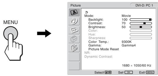
1 Display the main menu.
Press the MENU button to display the main menu on the screen.
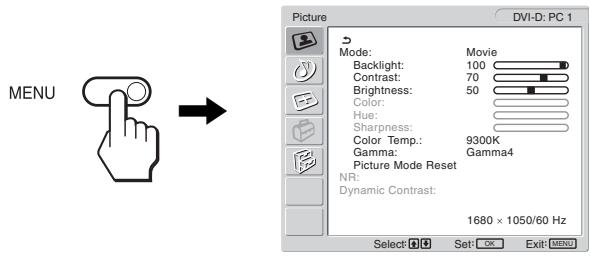
text_image
MENU Picture DVI-D: PC 1 Mode: Movie Backlight: 100 Contrast: 70 Brightness: 50 Color: Hue: Sharpness: Color Temp.: 9300K Gamma: Gamma4 Picture Mode Reset NR: Dynamic Contrast: 1680 × 1050/60 Hz Select: Set: Exit: MENU2 Select the menu.
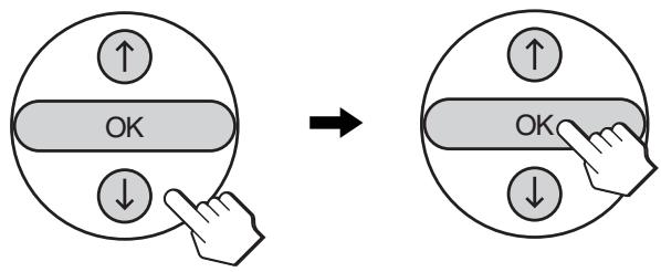
Press the ↑/↓ buttons to display the desired menu. Press the OK button to move to the first menu item.
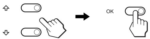
text_image
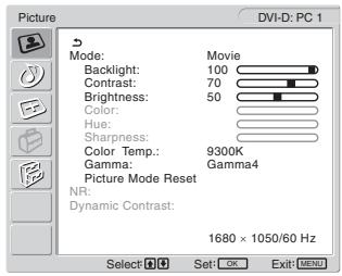
Diagram showing finger pressing and clicking control buttons with directional arrows and a 'OK' button3 Select the item you want to adjust.
Press the ↑/↓ buttons to select the item you want to adjust, then press the OK button.
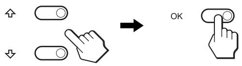
text_image
Diagram showing finger pressing and navigation icons with a 'OK' button, indicating press or action states.If ↩ is one of the menu items.
When you select ↩ and press the OK button, the display returns to the previous menu.
4 Adjust the item.
Press the ↑/↓ buttons to make the adjustment, then press the OK button.
When you press the OK button, the setting is stored, then the display returns to the previous menu.
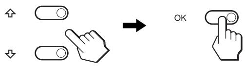
text_image
Diagram showing finger pressing and clicking icons with an 'OK' button, indicating press or navigation control.5 Close the menu.
Press the MENU button once to return to normal viewing. If no buttons are pressed, the menu closes automatically after about 45 seconds.
■ When you use the buttons on the remote control
1 Display the main menu.
Press the MENU button to display the main menu on the screen.
text_image
MENU Picture DVI-D: PC 1 Mode: Backlight: Contrast: Brightness: Color: Hue: Sharpness: Color Temp.: Gamma: Picture Mode Reset NR: Dynamic Contrast: 1680 × 1050/60 Hz Select Set: OK Exit: MENU2 Select the menu.
Press the ↑/↓ buttons to display the desired menu. Press the OK button to move to the first menu item.
text_image
↑ OK ↓ → ↑ OK ↓3 Select the item you want to adjust.
Press the ↑/↓ buttons to select the item you want to adjust, then press the OK button.

text_image
↑ OK ↓ → ↑ OK ↓If is one of the menu items.
When you select ↩ and press the OK button, the display returns to the previous menu.
4 Adjust the item.
Press the ↑/↓ buttons to make the adjustment, then press the OK button.
When you press the OK button, the setting is stored, then the display returns to the previous menu.

text_image
↑ OK ↓ → ↑ OK ↓5 Close the menu.
Press the MENU button once to return to normal viewing. If no buttons are pressed, the menu closes automatically after about 45 seconds.

■ Resetting the adjustments to the default settings
You can reset the adjustments using the “All Reset” menu. For more information about resetting the adjustments, see “Resetting to the default setting” on page 30.

Picture menu
You can adjust the following items using the “Picture” menu.
- Mode
Backlight
Contrast
Brightness
Color
Hue
Sharpness
Color Temp.
Gamma
Picture Mode Reset
- NR
• Dynamic Contrast
Tip
The “Backlight,” “Contrast,” “Brightness,” “Color,” “Hue,” “Sharpness,”
“Color Temp.,” and “Gamma” menus can be set for each Picture mode.
Also, Picture Mode can be set for each available input.
text_image
Picture DVI-D: PC 1 Mode: Backlight: Contrast: Brightness: Color: Hue: Sharpness: Color Temp.: Gamma: Picture Mode Reset NR: Dynamic Contrast: Movie 100 70 50 9300K Gamma: Gamma4 1680 × 1050/60 Hz Select Set: OK Exit: MENU■ Selecting the Picture Mode for PC 1/PC 2
You can select the appropriate screen brightness for your purpose.
1 Press the MENU button.
The main menu appears on the screen.
2 Press the ↑/↓ buttons to select 📄 (Picture) and press the OK button.
The “Picture” menu appears on the screen.
3 Press the ↑/↓ buttons to select "Mode" and press the OK button.
The “Mode” menu appears on the screen.
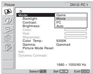
text_image
Picture DVI-D: PC 1 Mode: Game Backlight: Movie Contrast: PC Brightness: Auto Color: Hue: Sharpness: Color Temp.: 9300K Gamma: Gamma4 Picture Mode Reset NR: Dynamic Contrast: 1680 × 1050/60 Hz Select Set: OK Exit: MENU4 Press the ↑/↓ buttons to select the desired mode and press the OK button.
The default setting is “Movie.”
• Game: Bright picture.
- Movie: Clear picture with strong contrast.
• PC: Soft tone picture.
- Auto: Automatically adjusts the screen brightness according to the brightness of the surroundings (automatic brightness adjustment function). For more information, see “Automatic brightness adjustment function (light sensor)” on page 32.
Note
When the Picture Mode is set to “Auto,” you cannot adjust the backlight.
■ Selecting the Picture Mode for TV/COMPONENT/VIDEO 1/VIDEO 2
You can select the appropriate screen brightness for your purpose.
1 Press the MENU button.
The main menu appears on the screen.
2 Press the ↑/↓ buttons to select 📋 (Picture) and press the OK button.
The “Picture” menu appears on the screen.
3 Press the ↑/↓ buttons to select "Mode" and press the OK button.
The “Mode” menu appears on the screen.
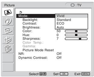
text_image
Picture Mode: Vivid Backlight: Standard Contrast: ECO Brightness: Auto Color: 50 Hue: 0 Sharpness: 7 Color Temp. Gamma: Picture Mode Reset NR: Off Dynamic Contrast: Off Select OK Set: OK Exit: MENU4 Press the ↑/↓ buttons to select the desired mode and press the OK button.
The default setting is “Vivid.”
- Vivid: Picture with enhanced contrast and sharpness.
- Standard: Picture with contrast that suits the room light.
• ECO: Picture with low brightness. - Auto: Automatically adjusts the screen brightness according to the brightness of the surroundings (automatic brightness adjustment function). For more information, see “Automatic brightness adjustment function (light sensor)” on page 32.
Note
When the Picture Mode is set to “Auto,” you cannot adjust the backlight.
■ Adjusting "Backlight"
If the screen is too bright, adjust the backlight to make the screen easier to see.
1 Press the MENU button.
The main menu appears on the screen.
2 Press the ↑/↓ buttons to select 📋 (Picture) and press the OK button.
The “Picture” menu appears on the screen.
3 Press the ↑/↓ buttons to select "Backlight" and press the OK button.
The “Backlight” menu appears on the screen.
4 Press the ↑/↓ buttons to adjust the light level and press the OK button.
■ Adjusting “Contrast”
You can adjust the picture contrast.
1 Press the MENU button.
The main menu appears on the screen.
2 Press the ↑/↓ buttons to select 📋 (Picture) and press the OK button.
The “Picture” menu appears on the screen.
3 Press the ↑/↓ buttons to select "Contrast" and press the OK button.
The “Contrast” menu appears on the screen.
4 Press the ↑/↓ buttons to adjust the contrast and press the OK button.
■ Adjusting “Brightness”
You can adjust the picture brightness (black level).
1 Press the MENU button.
The main menu appears on the screen.
2 Press the ↑/↓ buttons to select 📋 (Picture) and press the OK button.
The “Picture” menu appears on the screen.
3 Press the ↑/↓ buttons to select "Brightness" and press the OK button.
The “Brightness” menu appears on the screen.
4 Press the ↑/↓ buttons to adjust the brightness and press the OK button.
■ Adjusting “Color” (for TV/COMPONENT/VIDEO 1/VIDEO 2 only)
You can change the color intensity of the picture displayed.
1 Press the MENU button.
The main menu appears on the screen.
2 Press the ↑/↓ buttons to select 📋 (Picture) and press the OK button.
The “Picture” menu appears on the screen.
3 Press the ↑/↓ buttons to select "Color" and press the OK button.
The “Color” menu appears on the screen.
4 Press the ↑/↓ buttons to adjust the color intensity and press the OK button.
■ Adjusting “Hue” (for VIDEO 1/VIDEO 2 only)
You can change the color tones of the picture displayed. “Hue” can only be adjusted for NTSC color signal (e.g. USA video tapes).
1 Press the MENU button.
The main menu appears on the screen.
2 Press the ↑/↓ buttons to select 📋 (Picture) and press the OK button.
The “Picture” menu appears on the screen.
3 Press the ↑/↓ buttons to select "Hue" and press the OK button.
The “Hue” menu appears on the screen.
4 Press the ↑/↓ buttons to adjust the hue and press the OK button.
■ Adjusting “Sharpness” (for TV/COMPONENT/VIDEO 1/VIDEO 2 only)
You can adjust the sharpness of the edges of images, etc.
1 Press the MENU button.
The main menu appears on the screen.
2 Press the ↑/↓ buttons to select 📋 (Picture) and press the OK button.
The “Picture” menu appears on the screen.
3 Press the ↑/↓ buttons to select "Sharpness" and press the OK button.
The “Sharpness” menu appears on the screen.
4 Press the ↑/↓ buttons to adjust the sharpness and press the OK button.
■ Adjusting “Color Temp.” (for PC 1/PC 2 only)
You can select the picture's color level for the white color field from the default color temperature settings.
Also, if necessary, you can fine tune the color temperature.
1 Press the MENU button.
The main menu appears on the screen.
2 Press the ↑/↓ buttons to select 📋 (Picture) and press the OK button.
The “Picture” menu appears on the screen.
3 Press the ↑/↓ buttons to select "Color Temp." and press the OK button.
The “Color Temp.” menu appears on the screen.
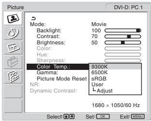
text_image
Picture DVI-D: PC 1 Mode: Backlight: Contrast: Brightness: Color: Hue: Sharpness: Color Temp: Gamma: Picture Mode Reset NR: Dynamic Contrast: Movie 100 70 50 9300K 6500K sRGB User L Adjust 1680 × 1050/60 Hz Select Set: OK Exit: MENU4 Press the ↑/↓ buttons to select the desired color temperature and press the OK button.
White balance changes from bluish to reddish as the color temperature is adjusted from 9,300K to 6,500K.
When you select “sRGB,” the colors adjust to the sRGB profile. (The sRGB color setting is an industry-standard color space protocol designed for computer products.) If you select “sRGB,” the color settings of your computer must be set to the sRGB profile.
Notes
- If a connected computer or other equipment is not sRGB-compliant, color cannot be adjusted to the sRGB profile.
- You cannot select “sRGB” when the Picture Mode is set to “Auto.”
- If you select “sRGB,” you cannot adjust “Contrast” and “Brightness” in the “Picture” menu. Also, you cannot adjust “Gamma.”
Fine tuning the color temperature
1 Press the MENU button.
The main menu appears on the screen.
2 Press the ↑/↓ buttons to select 📋 (Picture) and press the OK button.
The “Picture” menu appears on the screen.
3 Press the ↑/↓ buttons to select "Color Temp." and press the OK button.
The “Color Temp.” menu appears on the screen.
4 Press the ↑/↓ buttons to select "Adjust" and press the OK button.
The fine tuning menu for color temperature appears on the screen.
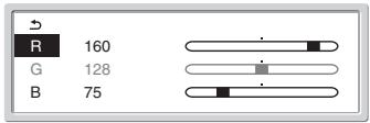
text_image
R 160 G 128 B 755 Press the ↑/↓ buttons to select R (Red) or B (Blue) and press the OK button. Then press the ↑/↓ buttons to adjust the color temperature and press the OK button.
Since this adjustment changes the color temperature by increasing or decreasing the R and B components with respect to G (green), the G component is fixed.
6 Press the ↑/↓ buttons to select ↩, then press the OK button.
The new color setting is stored in memory and automatically recalled whenever “User” is selected.
The “Color Temp.” menu appears on the screen.
■ Adjusting “Gamma” (for PC 1/PC 2 only)
You can associate the picture's color shade on the screen with the picture's original color shade.
1 Press the MENU button.
The main menu appears on the screen.
2 Press the ↑/↓ buttons to select 📋 (Picture) and press the OK button.
The “Picture” menu appears on the screen.
3 Press the ↑/↓ buttons to select "Gamma" and press the OK button.
The “Gamma” menu appears on the screen.
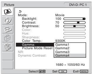
text_image
DVI-D: PC 1 Mode: Backlight: Contrast: Brightness: Color: Hue: Sharpness: Color Temp: 9300K Gamma: Picture Mode Reset NR: Dynamic Contrast: Gamma1 Gamma2 Gamma3 Gamma4 1680 × 1050/60 Hz Select: OK Exit: MENU4 Press the ↑/↓ buttons to select the desired mode and press the OK button.
■ Resetting Picture Mode to the default
You can reset the adjustments to the default settings.
1 Press the MENU button.
The main menu appears on the screen.
2 Press the ↑/↓ buttons to select 📋 (Picture) and press the OK button.
The “Picture” menu appears on the screen.
3 Press the ↑/↓ buttons to select "Picture Mode Reset" and press the OK button.
The “Picture Mode Reset” menu appears on the screen.
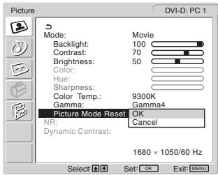
text_image
Picture DVI-D: PC 1 Mode: Backlight: Contrast: Brightness: Color: Hue: Sharpness: Color Temp.: 9300K Gamma: Picture Mode Reset OK Gamma4 NR: Dynamic Contrast: 1680 × 1050/60 Hz Select: OK Exit: MENU4 Press the ↑/↓ buttons to select the desired mode and press the OK button.
- OK: To reset the all items in the current Picture Mode to the default.
- Cancel: To cancel resetting and return to the “Picture” menu.
■ Setting “NR” (for TV/COMPONENT/VIDEO 1/VIDEO 2 only)
You can set the noise reduction function to on or off. This feature can be set for each available input.
1 Press the MENU button.
The main menu appears on the screen.
2 Press the ↑/↓ buttons to select 📋 (Picture) and press the OK button.
The “Picture” menu appears on the screen.
3 Press the ↑/↓ buttons to select "NR" and press the OK button.
The “NR” menu appears on the screen.
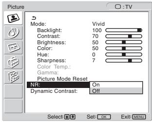
text_image
Picture Mode: Vivid Backlight: 100 Contrast: 70 Brightness: 50 Color: 50 Hue: 0 Sharpness: 7 Color Temp. Gamma: Picture Mode Reset NR: On Dynamic Contrast: Off Select: OK Set: OK Exit: MENU4 Press the ↑/↓ buttons to select the desired mode and press the OK button.
- On: The noise level is reduced.
- Off: The niose reduction function is turned off.
■ Setting “Dynamic Contrast” (for TV/COMPONENT/VIDEO 1/VIDEO 2 only)
You can set the “Dynamic Contrast” function to on or off. This feature can be set for each available input.
1 Press the MENU button.
The main menu appears on the screen.
2 Press the ↑/↓ buttons to select 📋 (Picture) and press the OK button.
The “Picture” menu appears on the screen.
3 Press the ↑/↓ buttons to select "Dynamic Contrast" and press the OK button.
The “Dynamic Contrast” menu appears on the screen.
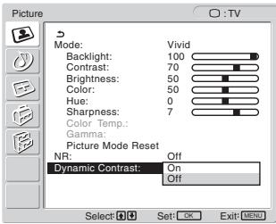
text_image
Picture Mode: Vivid Backlight: 100 Contrast: 70 Brightness: 50 Color: 50 Hue: 0 Sharpness: 7 Color Temp.: Gamma: Picture Mode Reset NR: Off Dynamic Contrast: On Off Select: OK Set: OK Exit: MENU4 Press the ↑/↓ buttons to select the desired mode and press the OK button.
- On: The picture contrast is enhanced.
- Off: The “Dynamic Contrast” function is turned off.
Notes
- Only when the Picture Mode is set to “Vivid” or “Standard,” the “Dynamic Contrast” is available.
- When the “Dynamic Contrast” function is set to “On,” the backlight becomes default and you can not adjust it.

text_image
Audio Surround: SRS WOW Treble: 0 Bass: 0 Balance: 0 Auto Volume: On Dual Sound: Stereo Audio Reset Select Set: OK Exit MENU
Audio menu
You can adjust the following items using the “Audio” menu.
The items in the “Audio” menu can be set for each available input.
- Surround
- Treble
- Bass
• Balance - Auto Volume
- Dual Sound
- Audio Reset
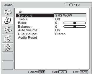
■ Setting "Surround"
1 Press the MENU button.
The main menu appears on the screen.
2 Press the ↑/↓ buttons to select 🎨 (Audio) and press the OK button.
The “Audio” menu appears on the screen.
3 Press the ↑/↓ buttons to select "Surround" and press the OK button.
The “Surround” menu appears on the screen.
text_image
Audio Surround: SRS WOW Treble: Off Bass: 0 Balance: 0 Auto Volume: On Dual Sound: Stereo Audio Reset Select Set OK Exit MENU4 Press the ↑/↓ buttons to select the desired mode and press the OK button.
- SRS WOW: Deep rich bass tone and clear high tone creates a rich surround sound experience, and movies and games, especially, can be enjoyed with powerful sound.
- Off: Turns off the SRS WOW effect.
Adopting the latest technology developed by SRS Labs, Inc., SRS WOW significantly improves the sound quality of various audio sources.
■ Adjusting “Treble,” “Bass,” and “Balance”
1 Press the MENU button.
The main menu appears on the screen.
2 Press the ↑/↓ buttons to select 🎨 (Audio) and press the OK button.
The “Audio” menu appears on the screen.
3 Press the ↑/↓ buttons to select "Treble," "Bass," or "Balance" and press the OK button.
4 Press the ↑/↓ buttons to adjust the level and press the OK button.
Note
Only when “Surround” is set to off, “Treble” and “Bass” can be adjusted.
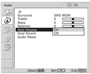
■ Setting “Auto Volume” (for TV/COMPONENT/VIDEO 1/VIDEO 2 only)
You can set the loudness of the sound to keep it at a specified level.
1 Press the MENU button.
The main menu appears on the screen.
2 Press the ↑/↓ buttons to select 🎯 (Audio) and press the OK button.
The “Audio” menu appears on the screen.
3 Press the ↑/↓ buttons to select "Auto Volume" and press the OK button.
The “Auto Volume” menu appears on the screen.
text_image
Audio Surround: SRS WOW Treble: 0 Bass: 0 Balance: 0 Auto Volume: On Dual Sound: Off Audio Reset Select: OK Exit: MENU4 Press the ↑/↓ buttons to select the desired mode and press the OK button.
- On: Loudness of the sound stays at the specified level, independent of the broadcast signal (e.g. in the case of advertisements).
- Off: Loudness of the sound changes automatically according to the broadcast signal.
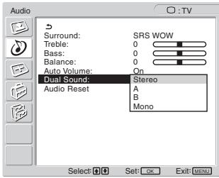
■ Setting “Dual Sound” (for TV/COMPONENT/VIDEO 1/VIDEO 2 only)
You can enjoy stereo, bilingual, and monaural programs.
1 Press the MENU button.
The main menu appears on the screen.
2 Press the ↑/↓ buttons to select 🎯 (Audio) and press the OK button.
The “Audio” menu appears on the screen.
3 Press the ↑/↓ buttons to select "Dual Sound" and press the OK button.
The “Dual Sound” menu appears on the screen.
text_image
Audio Surround: SRS WOW Treble: 0 Bass: 0 Balance: 0 Auto Volume: On Dual Sound: Stereo Audio Reset: A B Mono Select: OK Exit: MENU4 Press the ↑/↓ buttons to select the desired mode and press the OK button.
- Stereo: Stereo sound is output when viewing a program broadcast in stereo.
• A: Sound from channel 1 is output when viewing a bilingual broadcast.
• B: Sound from channel 2 is output when viewing a bilingual broadcast. - Mono: Monaural sound is output. (Use to reduce noise during weak stereo broadcasts.)
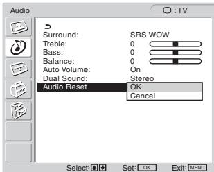
■ Resetting all audio settings to the default
You can reset the adjustments to the default settings.
1 Press the MENU button.
The main menu appears on the screen.
2 Press the ↑/↓ buttons to select 🎨 (Audio) and press the OK button.
The “Audio” menu appears on the screen.
3 Press the ↑/↓ buttons to select "Audio Reset" and press the OK button.
The “Audio Reset” menu appears on the screen.
text_image
Audio Surround: SRS WOW Treble: 0 Bass: 0 Balance: 0 Auto Volume: On Dual Sound: Stereo Audio Reset OK Cancel Select: OK Set: OK Exit: MENU4 Press the ↑/↓ buttons to select the desired mode and press the OK button.
- OK: To reset the all items in the “Audio” menu to the default.
- Cancel: To cancel resetting and return to the “Audio” menu.

Screen menu
You can adjust the following items using the “Screen” menu.
- Zoom
- Auto Adjust
- Phase
- Pitch
• H Center
• V Center - Resolution

text_image
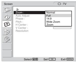
Screen HD15: PC 2 Zoom : Full Auto Adjust Phase : 30 Pitch : 0 H Center : 50 V Center : 50 Resolution 1680 × 1050/60 Hz Select: OK Set: OK Exit: MENUSetting "Zoom"
This feature lets you watch 4:3 normal broadcasts or other picture sizes such as Letter box movies in several “Zoom” modes.
A “Zoom” value is set for each available input.
Tip
You can also switch the "Zoom" setting by pressing the 🎨 button on the remote control repeatedly.
1 Press the MENU button.
The main menu appears on the screen.
2 Press the ↑/↓ buttons to select ☐ (Screen) and press the OK button.
The “Screen” menu appears on the screen.
3 Press the ↑/↓ buttons to select "Zoom" and press the OK button.
The “Zoom” menu appears on the screen.
text_image
Screen Zoom : Normal Auto Adjust Full Phase : 14:9 Pitch : Wide Zoom H Center : Zoom V Center : Resolution Select OK Set: OK Exit: MENU4 Press the ↑/↓ buttons to select the desired mode and press the OK button.
• Normal: Original aspect ratio.
• Full: A picture is enlarged to fill the 16:10 screen. Useful for viewing Squeeze signal.
• 14:9: The original 14:9 screen can be adjusted to the size between 4:3 and 16:9.
- Wide Zoom: A picture is enlarged horizontally (non-linear) to fill the 16:10 screen, keeping the original image as much as possible.
- Zoom: A picture is enlarged horizontally and vertically to an equal aspect ratio that fills a 16:10 screen. Useful for viewing Letter Box signal.
Notes
- If the input from either PC 1 or PC 2 is selected, “14:9,” “Zoom,” and “Wide Zoom” are unavailable.
- If the input from COMPONENT is selected and the video signal being input is 1080i format, “Wide Zoom” is unavailable.
- For “Normal” mode of PC 1 or PC 2, the input signal is displayed on the screen at its actual aspect ratio and black bars may appear at the top and bottom of the screen depending on the input signal.
■ Automatic picture quality adjustment function (for PC 2 only)
When the display receives an input signal, it automatically adjusts the picture's position and sharpness (phase/pitch), and ensures that a clear picture appears on the screen (page 32).
If the automatic picture quality adjustment function of this display seems to not completely adjust the picture
You can make further automatic adjustment of the picture quality for the current input signal (See “Auto Adjust” below).
If you still need to make further adjustments to the picture quality
You can manually adjust the picture's sharpness (phase/pitch) and position (horizontal/vertical position).
These adjustments are stored in memory and automatically recalled when the display receives a previously input and registered input signal.
■ Making further automatic adjustments to the picture quality for the current input signal (Auto Adjust) (for PC 2 only)
1 Press the MENU button.
The main menu appears on the screen.
2 Press the ↑/↓ buttons to select ☐ (Screen) and press the OK button.
The “Screen” menu appears on the screen.
3 Press the ↑/↓ buttons to select "Auto Adjust" and press the OK button.
Make the appropriate adjustments of the screen's phase, pitch and horizontal/vertical position for the current input signal and store them.
4 Press the ↑/↓ buttons to select the desired mode and press the OK button.
- OK: To start adjusting.
- Cancel: To cancel adjustments.
- Adjusting the picture's sharpness manually (Phase/Pitch) (for PC 2 only)
You can adjust the picture's sharpness as follows.
1 Set the resolution to 1,680 × 1,050 on the computer.
2 Load the CD-ROM.
3 Start the CD-ROM and display the test pattern.
For Windows User
When Auto run operates:
① Click Display Adjustment tool (Utility).
② Click “Adjust” and confirm the resolution and then click “Next.”
Test pattern for Pitch and Phase appears in order.
When Auto run fails to operate:
① Open “My Computer” and right click the CD-ROM icon. Go to “Explorer” and open the CD-ROM icon.
② Open [Utility] and then select [Windows].
③ Start [Win_Utility.exe].
Test pattern appears.
For Macintosh user
① Open [Utility] and then select [Mac].
② Start [Mac_Utility.exe].
Test pattern appears.
4 Press the MENU button.
The main menu appears on the screen.
5 Press the ↑/↓ buttons to select ☐ (Screen) and press the OK button.
The “Screen” menu appears on the screen.
6 Press the ↑/↓ buttons to select "Phase" and press the OK button.
The “Phase” adjustment menu appears on the screen.
7 Press the ↑/↓ buttons until the horizontal stripes are at a minimum.
Adjust so that the horizontal stripes are at a minimum.
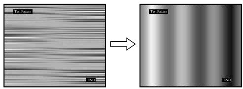
text_image
Test Pattern END Test Pattern END8 Press the OK button.
The main menu appears on the screen. If vertical stripes are observed over the entire screen, adjust the pitch using the following procedures.
9 Press the ↑/↓ buttons to select "Pitch" and press the OK button.
The “Pitch” adjustment menu appears on the screen.
10 Press the ↑/↓ buttons until the vertical stripes disappear.
Adjust so that the vertical stripes disappear.
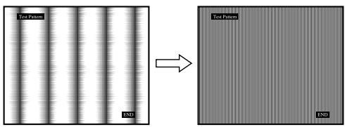
text_image
Test Pattern END Test Pattern END11 Click END on the screen to turn off the test pattern.
- Adjusting the picture’s position manually (H Center /V Center) (for PC 2 only)
If the picture is not in the centre of the screen, adjust the picture's centring as follows.
1 Set the resolution to 1,680 × 1,050 on the computer.
2 Load the CD-ROM.
3 Start the CD-ROM and display the test pattern.
For Windows User
When Auto run operates:
① Click Display Adjustment tool (Utility).
② Click “Adjust” and confirm the resolution and then click “Next.”
Test pattern for H Center and V Center appears in order.
When Auto run fails to operate:
① Open “My Computer” and right click the CD-ROM icon. Go to “Explorer” and open the CD-ROM icon.
② Open [Utility] and then select [Windows].
③ Start [Win_Utility.exe].
Test pattern appears.
For Macintosh user
① Open [Utility] and then select [Mac].
② Start [Mac_Utility.exe].
Test pattern appears.
4 Press the MENU button.
The main menu appears on the screen.
5 Press the ↑/↓ buttons to select ☐ (Screen) and press the OK button.
The “Screen” menu appears on the screen.
6 Press the ↑/↓ buttons to select "H Center" or "V Center" and press the OK button.
The “H Center” adjustment menu or “V Center” adjustment menu appears on the screen.
7 Press the ↑/↓ buttons to centre the test pattern on the screen.
8 Click END on the screen to turn off the test pattern.
- Adjusting the picture's position manually (V Center) (for TV/COMPONENT/VIDEO 1/VIDEO 2 only)
If you want to adjust the picture position up or down, when “14:9,” “Wide Zoom,” or “Zoom” is selected, adjust the picture’s centring as follows.
1 Press the MENU button.
The main menu appears on the screen.
2 Press the ↑/↓ buttons to select ☐ (Screen) and press the OK button.
The “Screen” menu appears on the screen.
3 Press the ↑/↓ buttons to select "V Center" and press the OK button.
The “V Center” adjustment menu appears on the screen.
4 Press the ↑/↓ buttons to adjust the picture position where you like.
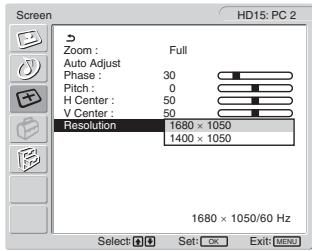
■ Changing the display resolution (Resolution) (for PC 2 only)
You can change the display resolution when the current input is different from the one displayed on the screen.
Tip
Some of the output signals from your computer may not be recognized on the display by assigning the default setting of resolution. The actual resolution may not be displayed as you have selected. Use this function only when you want to change the display resolution.
1 Press the MENU button.
The main menu appears on the screen.
2 Press the ↑/↓ buttons to select ☐ (Screen) and press the OK button.
The “Screen” menu appears on the screen.
3 Press the ↑/↓ buttons to select "Resolution" and press the OK button.
The “Resolution” menu appears on the screen.
text_image
Screen HD15: PC 2 Zoom : Full Auto Adjust Phase : 30 Pitch : 0 H Center : 50 V Center : 50 Resolution 1680 × 1050 1400 × 1050 1680 × 1050/60 Hz Select OK Set: OK Exit: MENU4 Press the ↑/↓ buttons to select the resolution you want to display, and press the OK button.

Option menu
You can adjust the following items using the “Option” menu.
- PIP/PAP
- TeleText
- Input Sensing
- Language
- Menu Position
- Menu Lock
- Demo Mode
- All Reset
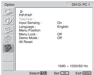
text_image
Option DVI-D: PC 1 PIP/PAP TeleText : Input Sensing : On Language : English Menu Position Menu Lock : Off Demo Mode : Off All Reset 1680 × 1050/60 Hz Select OK Exit MENU■ Setting “PIP” (Picture In Picture) or “PAP” (Picture And Picture) (for PC 1/PC 2 only)
When the “PIP/PAP Setting” menu is set to “PIP On” or “PAP On,” pictures from two input sources are displayed on the screen at the same time. When “PIP On” is set, the main picture is displayed in full size, and the sub picture is displayed smaller in the corner of the screen. When “PAP On” is set, two same-size pictures are displayed in the centre of the screen. The left screen shows the main picture, the right screen shows the sub picture. Also, you can choose either the sound from the main picture or the sub picture.
Tip
You can also switch the “PIP” or “PAP” setting by pressing the button repeatedly.
To switch the PIP or PAP function on and off
1 Press the MENU button.
The main menu appears on the screen.
2 Press the ↑/↓ buttons to select 📋 (Option) and press the OK button.
The “Option” menu appears on the screen.
3 Press the ↑/↓ buttons to select "PIP/PAP" and press the OK button.
4 Press the ↑/↓ buttons to select "PIP/PAP Setting" and press the OK button.
The “PIP/PAP Setting” menu appears on the screen.
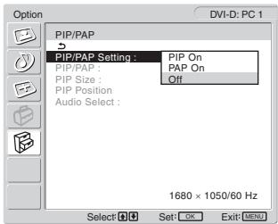
text_image
Option DVI-D: PC 1 PIP/PAP PIP/PAP Setting : PIP On PIP/PAP : PIP On PIP Size : Off PIP Position Audio Select : 1680 × 1050/60 Hz Select Set: OK Exit: MENU5 Press the ↑/↓ buttons to select the desired mode and press the OK button.
- PIP On: Pictures from two input sources are displayed on the screen. The main picture is displayed in full size, and the sub picture is displayed smaller in the corner of the screen. You can select the input for sub picture, the sub picture's position, size, and audio input source.
- PAP On: Pictures from two input sources are displayed on the screen. Two same-size pictures are displayed in the centre of the screen. The left screen shows the main picture, the right screen shows the sub picture. You can select the input for sub picture and audio input source.
- Off: The PIP or PAP function is turned off.
To select the input for sub picture (PIP function: On/PAP function: On)
1 Press the MENU button.
The main menu appears on the screen.
2 Press the ↑/↓ buttons to select 📄 (Option) and press the OK button.
The “Option” menu appears on the screen.
3 Press the ↑/↓ buttons to select "PIP/PAP" and press the OK button.
4 Press the ↑/↓ buttons to select "PIP/PAP Setting" and press the OK button.
The “PIP/PAP Setting” menu appears on the screen.
5 Press the ↑/↓ buttons to select "PIP On" or "PAP On" and press the OK button.
6 Press the ↑/↓ buttons to select "PIP/PAP" and press the OK button.
The “PIP/PAP” menu appears on the screen.
7 Press the ↑/↓ buttons to select the desired input source and press the OK button.
• TV: A TV program is displayed in the sub-picture area.
- COMPONENT: The picture sent from the video equipment connected to the display's video input jacks for COMPONENT is displayed in the sub-picture area.
- VIDEO 1: The picture sent from the video equipment connected to the display's video input jack for VIDEO 1 is displayed in the sub-picture area.
- VIDEO 2: The picture sent from the video equipment connected to the display's video input jacks for VIDEO 2 is displayed in the sub-picture area.
Note
The inputs for main/sub pictures must be selected as shown below.
| Main | Sub |
| PC 1 | TV |
| PC 2 | COMPONENTVIDEO 1VIDEO 2 |
Note
When displaying a program with teletexts on the sub-picture area, you cannot switch the PIP or PAP function using the PIP/PAP button on the remote control.
To switch off the PIP or PAP function, press the PIP/PAP button on the display, or set “PIP/PAP Setting” menu to “Off.”
To change the sub picture's size (PIP function: On)
1 Press the MENU button.
The main menu appears on the screen.
2 Press the ↑/↓ buttons to select 📄 (Option) and press the OK button.
The “Option” menu appears on the screen.
3 Press the ↑/↓ buttons to select "PIP/PAP" and press the OK button.
4 Press the ↑/↓ buttons to select "PIP/PAP Setting" and press the OK button.
The “PIP/PAP Setting” menu appears on the screen.
5 Press the ↑/↓ buttons to select "PIP On" and press the OK button.
6 Press the ↑/↓ buttons to select "PIP Size" and press the OK button.
The “PIP Size” menu appears on the screen.
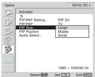
text_image
Option DVI-D: PC 1 PIP/PAP PIP/PAP Setting : PIP On PIP/PAP : TV PIP Size : Large PIP Position Middle Audio Select : Small 1680 × 1050/60 Hz Select OK Set: OK Exit MENU7 Press the ↑/↓ buttons to select the desired size and press the OK button.
- Large
- Middle
- Small
To change the sub picture's position (PIP function: On)
1 Press the MENU button.
The main menu appears on the screen.
2 Press the ↑/↓ buttons to select 📋 (Option) and press the OK button.
The “Option” menu appears on the screen.
3 Press the ↑/↓ buttons to select "PIP/PAP" and press the OK button.
4 Press the ↑/↓ buttons to select "PIP/PAP Setting" and press the OK button.
The “PIP/PAP Setting” menu appears on the screen.
5 Press the ↑/↓ buttons to select "PIP On" and press the OK button.
6 Press the ↑/↓ buttons to select "PIP Position" and press the OK button.
The “PIP Position” menu appears on the screen.
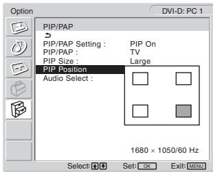
text_image
Option DVI-D: PC 1 PIP/PAP PIP/PAP Setting : PIP On PIP/PAP : TV PIP Size : Large PIP Position Audio Select : 1680 × 1050/60 Hz Select OK Set: OK Exit: MENU7 Press the ↑/↓ buttons to select the desired position and press the OK button.
You can choose one of 4 positions for the sub picture.
To select the audio input source (PIP function: On/PAP function: On)
1 Press the MENU button.
The main menu appears on the screen.
2 Press the ↑/↓ buttons to select Ⓔ (Option) and press the OK button.
The “Option” menu appears on the screen.
3 Press the ↑/↓ buttons to select "PIP/PAP" and press the OK button.
4 Press the ↑/↓ buttons to select "PIP/PAP Setting" and press the OK button.
The “PIP/PAP Setting” menu appears on the screen.
5 Press the ↑/↓ buttons to select "PIP On" or "PAP On" and press the OK button.
6 Press the ↑/↓ buttons to select "Audio Select" and press the OK button.
The “Audio Select” menu appears on the screen.
7 Press the ↑/↓ buttons to select the desired source and press the OK button.
- Main: The sound from the input source selected for the main picture will be used.
- Sub: The sound from the input source selected for the sub picture will be used.
Tip
If you select "Sub," ♩ is displayed in the screen.
■ Setting “TeleText” (for TV/VIDEO 1/VIDEO 2 only)
You can view the TeleText page, if the broadcaster offers this service. For details how to view TeleText, see “Using the TeleText service (for TV/VIDEO 1/VIDEO 2 only)” on page 33.
1 Press the MENU button.
The main menu appears on the screen.
2 Press the ↑/↓ buttons to select 📋 (Option) and press the OK button.
The “Option” menu appears on the screen.
3 Press the ↑/↓ buttons to select "TeleText" and press the OK button.
The “TeleText” menu appears on the screen.
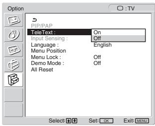
text_image
Option P/PAP TeleText : On Input Sensing : Off Language : English Menu Position Menu Lock : Off Demo Mode : Off All Reset Select: OK Set: OK Exit: MENU4 Press the ↑/↓ buttons to select either "Off" or "On" and press the OK button.
- Off: The TeleText mode is turned off.
- On: The TeleText mode is turned on.
Setting "Input Sensing" (for PC 1/PC 2 only)
You can set the display to automatically detect an available input signal, and switches the input.
1 Press the MENU button.
The main menu appears on the screen.
2 Press the ↑/↓ buttons to select 📋 (Option) and press the OK button.
The “Option” menu appears on the screen.
3 Press the ↑/↓ buttons to select "Input Sensing" and press the OK button.
The “Input Sensing” menu appears on the screen.
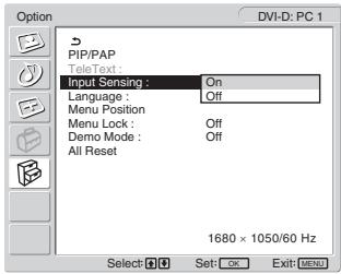
text_image
Option DVI-D: PC 1 PIP/PAP TeleText : Input Sensing : On Language : Off Menu Position Menu Lock : Off Demo Mode : Off All Reset 1680 × 1050/60 Hz Select OK Set-OK Exit-MENU4 Press the ↑/↓ buttons to select either "On" or "Off" and press the OK button.
- On: When a signal from the selected input source drops off or you have selected the input that receives no signal, the display try to detect a signal from the other computer input and display it, if available.
- Off: The display does not switch the input automatically. Press the → button or input select buttons to change the input.
■ Setting "Language"
1 Press the MENU button.
The main menu appears on the screen.
2 Press the ↑/↓ buttons to select 📋 (Option) and press the OK button.
The “Option” menu appears on the screen.
3 Press the ↑/↓ buttons to select "Language" and press the OK button.
The “Language” menu appears on the screen.
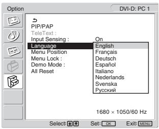
text_image
Option DVI-D: PC 1 PIP/PAP TeleText : Input Sensing : On Language English Menu Position Français Menu Lock: Deutsch Demo Mode : Español All Reset Italiano Nederlands Svenska Русский 1680 × 1050/60 Hz Select: OK Set: OK Exit: MENU4 Press the ↑/↓ buttons to select a language and press the OK button.
- English
- Français: French
- Deutsch: German
- Español: Spanish
- Italiano: Italian
- Nederlands: Dutch
- Svenska: Swedish
• Русский: Russian
■ Setting "Menu Position"
You can change the menu position if it is blocking an image on the screen.
1 Press the MENU button.
The main menu appears on the screen.
2 Press the ↑/↓ buttons to select Ⓔ (Option) and press the OK button.
The “Option” menu appears on the screen.
3 Press the ↑/↓ buttons to select "Menu Position" and press the OK button.
The “Menu Position” menu appears on the screen.
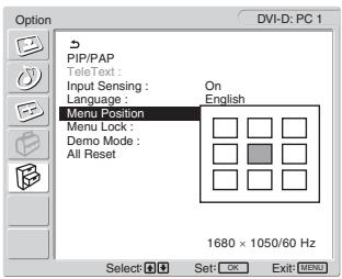
text_image
Option DVI-D: PC 1 PIP/PAP TeleText : Input Sensing : Language : Menu Position On English Menu Lock : Demo Mode : All Reset 1680 × 1050/60 Hz Select: Set: OK Exit: MENU4 Press the ↑/↓ buttons to select the desired position and press the OK button.
You can choose one of 9 positions where the menu will appear.
■ Setting "Menu Lock"
You can lock in the menu adjustments to prevent accidental adjustments or resetting.
1 Press the MENU button.
The main menu appears on the screen.
2 Press the ↑/↓ buttons to select 📋 (Option) and press the OK button.
The “Option” menu appears on the screen.
3 Press the ↑/↓ buttons to select "Menu Lock" and press the OK button.
The “Menu Lock” menu appears on the screen.
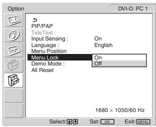
text_image
Option DVI-D: PC 1 PIP/PAP TeleText : Input Sensing : On Language : English Menu Position Menu Lock On Demo Mode : Off All Reset 1680 × 1050/60 Hz Select: OK Set: OK Exit: MENU4 Press the ↑/↓ buttons to select either "On" or "Off" and press the OK button.
- On: If “On” has been selected, when you attempt to operate the MENU button, the “Option” menu appears on the screen; when you attempt to operate the ⏻ button, the ⏻ icon appears.
- Off: The lock on the menu adjustments is released.
To release the lock of the menu adjustments
1 Press the MENU button.
The “Option” menu appears.
2 Press the OK button.
The “Menu Lock” menu appears.
3 Press the ↑/↓ buttons to select "Off" and press the OK button.
The lock on the menu adjustments is released.
■ Setting “Demo Mode”
You can set the “Demo Mode” function to on or off. If you set the “Demo Mode” menu to “On,” the demonstration image appears on the screen.
To cancel the “Demo Mode” function, set the “Demo Mode” menu to “Off”.
Note
While the “Demo Mode” is on, only the ⏻ (power) switch and MENU button will operate.
■ Resetting to the default setting
This function resets the adjustments for all inputs to the default setting. Use this function with care.
1 Press the MENU button. The main menu appears on the screen.
2 Press the ↑/↓ buttons to select Ⓔ (Option) and press the OK button.
The “Option” menu appears on the screen.
3 Press the ↑/↓ buttons to select "All Reset" and press the OK button.
The “All Reset” menu appears on the screen.
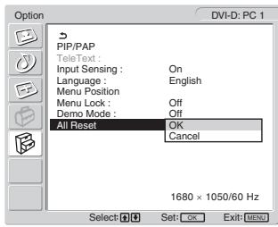
text_image
Option DVI-D: PC 1 PIP/PAP TeleText : Input Sensing : On Language : English Menu Position Menu Lock : Off Demo Mode : Off All Reset OK Cancel 1680 × 1050/60 Hz Select: H G Set: OK Exit: MENU4 Press the ↑/↓ buttons to select the desired mode and press the OK button.
- OK: To reset all of the adjustment data to the default settings. Note that the “Language” setting is not reset by this method.
- Cancel: To cancel resetting and return to the menu screen.
Note
If you select OK in step 4, the adjustments made using the “Set Up” menu are also set to the default. Therefore, after selecting OK, you need to set up your channels again to watch TV programs (page 15).
Technical Features
Controlling the volume
Using the display's speakers or headphones, you can listen to sound from your computer or other equipment connected to the display's audio input jacks.
You can control the volume by inputting either PC 1/PC 2 or TV/COMPONENT/VIDEO 1/VIDEO 2.
You can control the volume by using the “Volume” adjustment bar.
1 Press the ▲+/- buttons when there is no menu displayed on the screen.
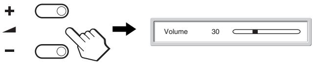
text_image
+ - Volume 302 Press the ▲+/- buttons to set the desired volume level.
The bar automatically disappears after about 5 seconds.
Notes
- You cannot adjust the volume using the / buttons on the display when the main menu is displayed on the screen. Use the +/− buttons on the remote control instead.
- You cannot adjust the volume using the ↑/↓ buttons on the remote control.
- When your display is in power saving mode, no sound comes from the speakers or the headphones.
Power saving function
If the display is connected to a computer or video graphics board that is DPMS (Display Power Management Standard) for Analog input/DMPM (DVI Digital Monitor Power management) for Digital input compliant, the display will automatically reduce power consumption as shown below.
| Power mode | Power consumption | ⏻ (power) indicator |
| normal operation | 99 W (max.) | green |
| active off* (deep sleep)** | 2 W (max.) | orange |
* When your computer enters the “active off” mode, the input signal is cut and “No Input Signal” appears on the screen. After 5 seconds, the display enters the power saving mode.
** “Deep sleep” is a power saving mode defined by the Environmental Protection Agency.
Tip
When the display is in the standby mode or the Sleep timer is activated, the ⏻ (power) indicator lights up in red.
Setting the Picture Mode
You can select the Picture Mode using the ⏻ button or “Mode” in the “Picture” menu.
When you select “Auto,” the display automatically adjusts the screen brightness according to the brightness of the surroundings (Automatic brightness adjustment function). For more information, see “Automatic brightness adjustment function (light sensor)”.
For details on using the “Mode” menu, see page 19.
For details on using the ⚙ button, see below.
Press the ⚙ button repeatedly.
Each time you press the ⚙ button, the Picture Mode changes as follows.
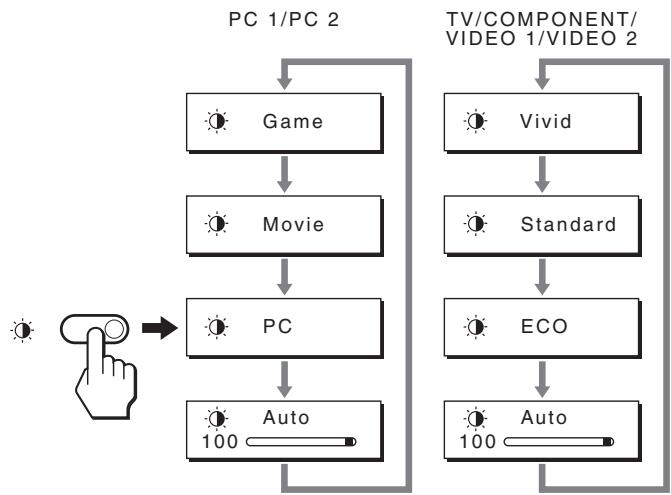
flowchart
graph TD
    A["PC 1/PC 2"] --> B["Game"]
    B --> C["Movie"]
    C --> D["PC"]
    D --> E["Auto 100"]
    F["TV/COMPONENT/VIDEO 1/VIDEO 2"] --> G["Vivid"]
    G --> H["Standard"]
    H --> I["ECO"]
    I --> J["Auto 100"]
    J --> K["End"]
Each indication appears on the screen and Picture Mode is changed. The menu automatically disappears after about 10 seconds.
Automatic brightness adjustment function (light sensor)
This display is provided with a feature to automatically adjust the screen brightness according to the brightness of the surroundings. The brightness of the screen is set to the most appropriate level by setting the Picture Mode to “Auto” with the ⏻ button or “Mode” in the “Picture” menu. (When you select the input from PC 1 or PC 2, “Movie” is selected as the default. When you select the input from COMPONENT, VIDEO 1, VIDEO 2, or TV, “Vivid” is selected as the default.)
Also, when you set the Picture Mode to “Auto” with the ⏻ button, the adjustment bar is displayed. You can adjust the bar with the ↑/↓ buttons. Screen brightness changes according to the level you set.
Automatic picture quality adjustment function (for PC 2 only)
When the display receives an input signal, it automatically adjusts the picture's position and sharpness (phase/pitch), and ensures that a clear picture appears on the screen.
The factory preset mode
When the display receives an input signal, it automatically matches the signal to one of the factory preset modes stored in the display's memory to provide a high quality picture at the centre of the screen. If the input signal matches the factory preset mode, the picture appears on the screen automatically with the appropriate default adjustments.
If input signals do not match one of the factory preset modes
When the display receives an input signal that does not match one of the factory preset modes, the automatic picture quality adjustment function of this display is activated to ensure that a clear picture always appears on the screen (within the following display frequency ranges):
Horizontal frequency: 28–86 kHz
Vertical frequency: 48–85 Hz (resolution < 1,280 × 1,024)
48–75 Hz (resolution < 1,400 × 1,050)
48–60 Hz (resolution ≤ 1,680 × 1,050)
Consequently, the first time the display receives input signals that do not match one of the factory preset modes, the display may take a longer time than normal to display the picture on the screen. This adjustment data is automatically stored in memory so that next time, the display will function in the same way as when the display receives the signals that match one of the factory preset modes.
If you adjust the phase, pitch, and picture position manually
For some input signals, the automatic picture quality adjustment function of this display may not completely adjust the picture position, phase, and pitch. In this case, you can set these adjustments manually (page 26). If you set these adjustments manually, they are stored in memory as user modes and automatically recalled whenever the display receives the same input signals.
Turning off the display automatically (for TV/COMPONENT/VIDEO 1/VIDEO 2 only)
You can set the display to turn off automatically after a predetermined period of time (15, 30, 45, 60, or 90 minutes).
Press the ⏻ button on the remote control repeatedly.
Each time you press the ⏻ button, the period of time changes as follows:
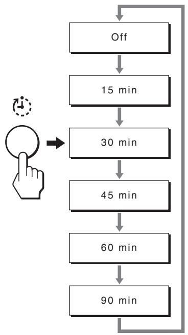
flowchart
graph TD
    A["Off"] --> B["15 min"]
    B --> C["30 min"]
    C --> D["45 min"]
    D --> E["60 min"]
    E --> F["90 min"]
    F --> A
To cancel the Sleep timer
Press the Ⓧ button repeatedly until “Off” appears.
Tips
- If you turn the display off, and then turn it on again, the Sleep timer is set to off.
- While the Sleep timer is activated, the ⏻ (power) indicator lights up in red.
- If you press the sleep button, while Sleep timer is activated, the remaining time in the timer is displayed until you turn the display off.
- If the input from PC 1 or PC 2 is selected while Sleep timer is activated, Sleep timer is cancelled.
Using the TeleText service (for TV/VIDEO 1/VIDEO 2 only)
TeleText is an information service transmitted by most TV stations. The index page of the TeleText service gives you information on how to use the service. To view TeleText, set the “TeleText” menu in the “Option” menu to “On” and use the remote control buttons as indicated below.
Notes
- Note that the Ⓞ (TeleText) button may not work in certain viewing areas because the TeleText service is not provided.
- Make sure you use a channel (TV Broadcast) with a strong signal, otherwise TeleText errors may occur.
To switch on the TeleText mode
After selecting the TV channel which carries the TeleText service you want to view, press the Ⓤ button.
Each time you press the Ⓞ button, mode changes “off →
TeleText → TV + TeleText → off....”
To select a TeleText page
Input three digits for the page number, using the 0-9 buttons.
Tips
- If you make a mistake, retype the correct page number.
- If the counter on the screen continues searching, it is because this page is not available. In this case, input another page number.
To access the next or preceding page
Press the □ or □ buttons.
To freeze a TeleText page
Some TeleText pages have sub-pages which follow on automatically. To freeze them, press the ➕ button. Press it again to cancel the freeze.
To reveal concealed information (e.g. answers to a quiz)
Press the ☐ button. Press it again to conceal the information.
To select a sub page
Press the ↑/↓ buttons on the remote control to watch the desired page.
■ Using the Fastext service
The Fastext service lets you access pages with one push of a button.
While you are in the TeleText mode and Fastext is broadcast, a color coded menu appears at the bottom of the TeleText page. Press the color button (red, green, yellow or blue) to access the corresponding page.
Troubleshooting
Before contacting technical support, refer to this section.
On-screen messages
If there is something wrong with the input signal, one of the following messages appears on the screen. To solve the problem, see “Trouble symptoms and remedies” on page 35.
If "Out Of Range" appears on the screen
This indicates that the input signal is not supported by the display's specifications. Check the following items. For more information about on-screen messages, see “Trouble symptoms and remedies” on page 35.
If "xxx.x kHz / xxx Hz" is displayed
This indicates that either the horizontal or vertical frequency is not supported by the display's specifications. The figures indicate the horizontal and vertical frequencies of the current input signal.
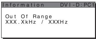
text_image
Information DVI-D:PC1 Out Of Range XXX.XkHz / XXXHzIf "Resolution >1680 × 1050 " is displayed
This indicates that the resolution is not supported by the display's specifications.
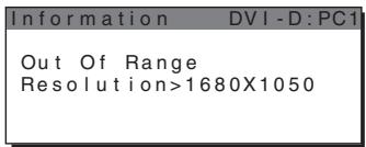
text_image
Information DVI-D:PCI Out Of Range Resolution>1680X1050If "No Input Signal" appears on the screen
This indicates that no signal is being input via the currently selected connector.
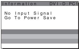
text_image
Information DVI-D:PC1 No Input Signal Go To Power SaveIf "Cable Disconnected" appears on the screen
This indicates that the video signal cable has been disconnected from the currently selected connector. After 45 seconds, the Power Save Mode activates.
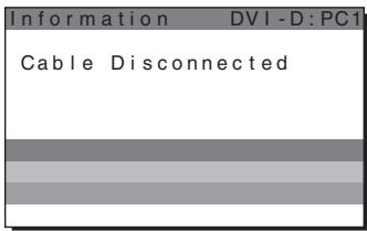
text_image
Information DVI-D:PC1 Cable DisconnectedIf “Power will be turned off by off timer soon” appears on the screen
This indicates that the power provided to the display will be turned off by off timer in 1 minute.
If “Power will be turned off by auto shut off soon” appears on the screen
This indicates that the power provided to the display will be turned off by auto shut off timer in 1 minute.
If "Feature Not Available" appears on the screen
This indicates that the function which you have attempted to operate is not available.
Trouble symptoms and remedies
If a problem occurs as a result of a connected computer or other equipment, refer to the connected computer/equipment's instruction manual.
For PC 1/PC 2
| Symptom | Check these items |
| No picture. | |
| If the ⏻ (power) indicator is not lit, or if the ⏻ (power) indicator will not light up when the ⏻ (power) switch is pressed, | · Check that the mains lead is properly connected. |
| If “Cable Disconnected” appears on the screen, | · Check that the video signal cable is properly connected and all plugs are firmly seated in their sockets (page 9).· Check that the video input connector’s pins are not bent or pushed in.· Check that the input select setting is correct (page 13).· A non-supplied video signal cable is connected. If you connect a non-supplied video signal cable, “Cable Disconnected” may appear on the screen. This is not a malfunction. |
| If “No Input Signal” appears on the screen, or the ⏻ (power) indicator is orange, | · Check that the video signal cable is properly connected and all plugs are firmly seated in their sockets (page 9).· Check that the video input connector’s pins are not bent or pushed in.· Check that the input select setting is correct (page 13).■Problem caused by a computer or other equipment connected, and not caused by the display· The computer is in the power saving mode. Try pressing any key on the keyboard or moving the mouse.· Check that your graphics board is installed properly.· Change your graphic board to the latest driver. Or match the version of your graphic board to the current OS.· When using a laptop computer, set the output of your computer to video out (for details on video out setting, contact your computer manufacturer).· Check that the computer’s power is on.· Restart the computer. |
| If “Out Of Range” appears on the screen (page 34), | ■Problem caused by a computer or other equipment connected, and not caused by the display· Check that the video frequency range is within that specified for the display. If you replaced an old display with this display, reconnect the old display and adjust the computer’s graphics board within the following ranges:Horizontal frequency: 28–86 kHz (Analog RGB), 28–68 kHz (Digital RGB)Vertical frequency: 48–85 Hz (resolution < 1,280 × 1,024), 48–75 Hz (resolution < 1,400 × 1,050), 48–60 Hz (resolution ≤ 1,680 × 1,050) (Analog RGB), 60 Hz (Digital RGB)Resolution: 1,680 × 1,050 or less· Start your OS in Safe mode and restart the computer after setting the resolution. The setting of safe mode varies depending on your OS. For more details, contact your computer manufacturer. |
| If using Windows, | · If you replaced an old display with this display, reconnect the old display and do the following. Select “SONY” from the “Manufacturers” list and select “MFM-HT205” from the “Models” list on the Windows device selection screen. If “MFM-HT205” does not appear in the “Models” list, try “Plug & Play.” |
| If using a Macintosh system, | · When connecting a Macintosh computer, use an adapter (not supplied) if necessary. Connect the adapter to the computer before connecting the video signal cable. |
| Picture flickers, bounces, oscillates, or is scrambled. | Adjust the pitch and phase (PC 2 only) (page 26).Problem caused by a computer or other equipment connected, and not caused by the displayCheck your graphics board manual for the proper display setting.Confirm that the graphics mode (VESA, Macintosh 19" Color, etc.) and the frequency of the input signal are supported by this display. Even if the frequency is within the proper range, some graphics boards may have a sync pulse that is too narrow for the display to sync with correctly.This display does not process interlace signals. Set for progressive signals.Adjust the computer's refresh rate (vertical frequency) to obtain the best possible picture (60 Hz is recommended). |
| Picture is fuzzy. | Adjust the contrast and brightness (page 20).Adjusting the sharpness (page 21).Adjust the pitch and phase (PC 2 only) (page 26).Problem caused by a computer or other equipment connected, and not caused by the displaySet the resolution to 1,680 × 1,050 on your computer. |
| Picture is ghosting. | Eliminate the use of video cable extensions and/or video switch boxes.Check that all plugs are firmly seated in their sockets. |
| Picture is not centred or sized properly (PC 2 only). | Adjust the pitch and phase (page 26).Adjust the picture position (page 26). Note that some video modes do not fill the screen to the edges. |
| Picture becomes vertically stretched, or picture size looks strange. | Problem caused by a computer or other equipment connected, and not caused by the displaySet the resolution to 1,680 × 1,050 on your computer. |
| Picture is too small. | Problem caused by a computer or other equipment connected, and not caused by the displaySet the resolution to 1,680 × 1,050 on your computer. |
| Picture is dark. | Adjust the backlight (page 20).Adjust the brightness (page 20).Adjust the gamma on the “Gamma” menu (page 22).It takes a few minutes for the display to become bright after turning on the display.When the Picture Mode is set to “Auto,” the display brightness may become darker in low ambient light (pages 19, 32). |
| Wavy or elliptical pattern (moire) is visible. | Adjust the pitch and phase (PC 2 only) (page 26). |
| Color is not uniform. | Adjust the pitch and phase (PC 2 only) (page 26). |
| White does not look white. | Adjust the color temperature (page 21). |
| Display buttons do not operate (O _T appears on the screen). | If “Menu Lock” is set to “On,” set it to “Off” (page 30). |
| Resolution displayed on the menu screen is incorrect. | Depending on the graphics board setting, the resolution displayed on the menu screen may not coincide with the one set on the computer. |
| Symptom | Check these items |
| No picture. | |
| Cannot receive any channels. | Make sure the mains lead is connected securely.Turn on the power of the display.Check aerial cable connections. |
| No sound./Noisy sound. | |
| Good picture, no sound. | Check audio cable connections.Check the volume control.Press the or + button so that “Muting” disappears from the screen (pages 17, 31).Disconnect your headphones. |
| Black bars appear besides, top and bottom of the screen. | It is depending on the type of the video source. Adjust the screen size using the “Zoom” menu (page 25). |
| Remote control does not operate. | The batteries could be weak. Replace the batteries.Check the polarity of the batteries.If the (power) indicator on the display does not light, press the (power) switch on the display.If you intend to operate the TV functions, check the TV input is selected.If you intend to operate the TV functions with the “PIP” or “PAP” function, check the TV input is selected for sub picture.When displaying a program with teletexts on the sub-picture area, you cannot switch the PIP or PAP function using the PIP/PAP button on the remote control. The PIP/PAP button is available only for the TeleText service (page 28). |
| Noisy picture when viewing a TV channel. | Set the “NR” menu to “On” to reduce the noise on the picture (page 22).Decrease the setting value for the “Sharpness” menu (page 21). |
If any problem persists, call your authorised Sony dealer and give the following information:
• Model name: MFM-HT205
- Serial number
• Detailed description of the problem
- Date of purchase
- Name and specifications of your computer and graphics board
- Type of input signals (PC 1/PC 2/TV/COMPONENT/VIDEO 1/VIDEO 2)
Specifications
LCD panel
Panel type: a-Si TFT Active Matrix
Screen size:
20 inch (51 cm)
Display resolution:
Horizontal: Max. 1,680 dots
Vertical: Max. 1,050 lines
Signal input
PC 1
Signal format:
Digital RGB (DVI-D) (TMDS Single link)
Operating frequency:
Horizontal: 28–68 kHz
Vertical: 60 Hz
Audio:
Operating frequency:
Horizontal: 28–86 kHz
Vertical: 48–85 Hz (resolution < 1,280 × 1,024)
48–75 Hz (resolution < 1,400 × 1,050)
48–60 Hz (resolution ≤ 1,680 × 1,050)
Signal levels:
RGB signal: 0.7 Vp-p, 75 Ω, positive
SYNC signal:
TTL level, 2.2 kΩ, positive or negative (Separate horizontal and vertical, or composite sync)
0.3 Vp-p, 75 Ω, negative (Sync on green)
Audio:
D/K: R1 to R12, R21 to R69
L: F2 to F10, B-Q, F21 to F69
I: UHF B21 to B69
Aerial:
75-ohm external terminal for VHF/UHF
COMPONENT
Signal standard:
Component video (Y, P_B , P_R ) (Phono jack)
Y: 1.0 Vp-p, 75-ohm unbalanced, sync negative
P_B : 0.7 Vp-p, 75 Ω
P_R : 0.7 Vp-p, 75 Ω
Signal format:
480i (525i), 480p (525p), 576i (625i), 576p (625p),
720p (750p), 1080i (1125i)
Audio:
Phono jack (stereo), 500 mVrms
VIDEO 1
Signal standard:
21-pin scart connector (CENELEC standard)
including AUDIO/VIDEO input, RGB input, and TV
AUDIO/VIDEO output
VIDEO 2
Signal standard:
100–240 V AC, 50–60 Hz
Max. 1.2 A
Power consumption
In use (Max.): 99 W
In standby (Max.): 2 W
Operating temperature
0–35°C
Dimensions (width/height/depth)
Display (upright):
Approx. 523.7 × 406.8 × 197 mm
Mass
Approx. 8.2 kg
Accessories
See page 9.
Design and specifications are subject to change without notice.
LCD Multi Function Display
MFM-HT205
Owner's Record
The model and serial numbers are located at the rear of the unit. Record these numbers in the spaces provided below. Refer to them whenever you call upon your dealer regarding this product. Model No. ____ Serial No. ____
WARNING
To reduce the risk of fire or electric shock, do not expose this apparatus to rain or moisture.
Dangerously high voltages are present inside the unit. Do not open the cabinet. Refer servicing to qualified personnel only.
FCC Notice
This equipment has been tested and found to comply with the limits for a Class B digital device, pursuant to Part 15 of the FCC Rules. These limits are designed to provide reasonable protection against harmful interference in a residential installation. This equipment generates, uses, and can radiate radio frequency energy and, if not installed and used in accordance with the instructions, may cause harmful interference to radio communications. However, there is no guarantee that interference will not occur in a particular installation. If this equipment does cause harmful interference to radio or television reception, which can be determined by turning the equipment off and on, the user is encouraged to try to correct the interference by one or more of the following measures:
– Reorient or relocate the receiving antenna.
– Increase the separation between the equipment and receiver.
- Connect the equipment into an outlet on a circuit different from that to which the receiver is connected.
- Consult the dealer or an experienced radio/TV technician for help. You are cautioned that any changes or modifications not expressly approved in this manual could void your authority to operate this equipment.
IMPORTANTE
If you have any questions about this product, you may call; Sony Customer Information Services Center 1-800-222-7669 or http://www.sony.com/
Declaration of Conformity
Trade Name: SONY Model: MFM-HT205 Responsible Party: Sony Electronics Inc. Address: 16450 W. Bernardo Dr, San Diego, CA 92127 U.S.A. Telephone Number: 858-942-2230
This device complies with part 15 of the FCC rules. Operation is subject to the following two conditions: (1) This device may not cause harmful interference, and (2) this device must accept any interference received, including interference that may cause undesired operation.
NOTICE
This notice is applicable for USA/Canada only. If shipped to USA/Canada, install only a UL LISTED/CSA LABELLED power supply cord meeting the following specifications:
SPECIFICATIONS
Plug Type Nema-Plug 5-15p Cord Type SVT or SJT, minimum 3 × 18 AWG Length Maximum 15 feet Rating Minimum 7 A, 125 V
NOTICE
natural_image
Technical line drawing of a plug with three leads and two connectors (no text or symbols)- Câble coaxial 75 ohms
natural_image
Technical line drawing of a mechanical component with a curved handle and mounting bracket (no text or symbols)Remarque
text_image
Diagram showing a no-prohibition sign above a vehicle seatbelt mechanism, indicating no barrier or restriction.text_image
approx. 20°natural_image
Diagram showing a device being processed from a left-side view to an exploded view, with no visible text or symbols.Remarques
text_image
Diagram showing finger pressing and clicking control buttons with directional arrows and a 'OK' buttontext_image
Diagram showing finger pressing and navigation buttons with directional arrows and a 'OK' buttontext_image
Diagram showing finger pressing and clicking icons with a right-pointing arrow labeled 'OK'5 Quittez le menu.
text_image
↑ OK ↓ → ↑ OK ↓text_image
↑ OK ↓ → ↑ OK ↓text_image
↑ OK ↓ → ↑ OK ↓5 Quittez le menu.
text_image
+ - Volume 30Horizontale : 28–68 kHz
Verticale : 60 Hz
Audio :
Mini-prise stéréo, 500 mV eff.
PC 2
Format de signal :
RVB analogique (HD-15D-sub)
480i (525i), 480p (525p), 576i (625i), 576p (625p),
720p (750p), 1080i (1125i)
Audio :
Prise Phono (stéréo), 500 mV eff
VIDEO 1
Norme de signal :
100–240 V CA, 50–60 Hz
Max. 1,2 A
LCD Multi Function Display
MFM-HT205
Owner's Record
The model and serial numbers are located at the rear of the unit. Record these numbers in the spaces provided below. Refer to them whenever you call upon your dealer regarding this product. Model No. ____ Serial No. ____
WARNING
To reduce the risk of fire or electric shock, do not expose this apparatus to rain or moisture.
Dangerously high voltages are present inside the unit. Do not open the cabinet. Refer servicing to qualified personnel only.
FCC Notice
This equipment has been tested and found to comply with the limits for a Class B digital device, pursuant to Part 15 of the FCC Rules. These limits are designed to provide reasonable protection against harmful interference in a residential installation. This equipment generates, uses, and can radiate radio frequency energy and, if not installed and used in accordance with the instructions, may cause harmful interference to radio communications. However, there is no guarantee that interference will not occur in a particular installation. If this equipment does cause harmful interference to radio or television reception, which can be determined by turning the equipment off and on, the user is encouraged to try to correct the interference by one or more of the following measures:
– Reorient or relocate the receiving antenna.
– Increase the separation between the equipment and receiver.
- Connect the equipment into an outlet on a circuit different from that to which the receiver is connected.
- Consult the dealer or an experienced radio/TV technician for help. You are cautioned that any changes or modifications not expressly approved in this manual could void your authority to operate this equipment.
IMPORTANTE
If you have any questions about this product, you may call; Sony Customer Information Services Center 1-800-222-7669 or http://www.sony.com/
Declaration of Conformity
Trade Name: SONY Model: MFM-HT205 Responsible Party: Sony Electronics Inc. Address: 16450 W. Bernardo Dr, San Diego, CA 92127 U.S.A. Telephone Number: 858-942-2230
This device complies with part 15 of the FCC rules. Operation is subject to the following two conditions: (1) This device may not cause harmful interference, and (2) this device must accept any interference received, including interference that may cause undesired operation.
NOTICE
This notice is applicable for USA/Canada only. If shipped to USA/Canada, install only a UL LISTED/CSA LABELLED power supply cord meeting the following specifications:
SPECIFICATIONS
Plug Type Nema-Plug 5-15p Cord Type SVT or SJT, minimum 3 × 18 AWG Length Maximum 15 feet Rating Minimum 7 A, 125 V
NOTICE
natural_image
Technical line drawing of a plug with three leads and a terminal connector (no text or symbols)Índice
Precauciones 5
natural_image
Technical line drawing of a mechanical component with a handle and mounting bracket (no text or symbols)Nota
text_image
Diagram showing a no-prohibited parking sign above a vehicle seatbelt mechanismnatural_image
Diagram showing a device component before and after assembly, with no visible text or symbolsNotas
text_image
Diagram showing finger pressing and clicking icons with an 'OK' button, indicating press or click action.text_image
Diagram showing finger pressing and navigation icons with directional arrows and a 'OK' buttontext_image
Diagram showing finger pressing and clicking icons with an 'OK' button, indicating press or navigation control.5 Cierre el menú.
text_image
↑ OK ↓ → ↑ OK ↓text_image
↑ OK ↓ → ↑ OK ↓text_image
↑ OK ↓ → ↑ OK ↓5 Cierre el menú.
Horizontal: 28–68 kHz
Vertical: 60 Hz
Audio:
Minitoma estéreo, 500 mVrms
PC 2
Horizontal: 28–86 kHz
Vertical: 48–85 Hz (resolución < 1.280 × 1.024)
48–75 Hz (resolución < 1.400 × 1.050)
48–60 Hz (resolución ≤ 1.680 × 1.050)
Niveles de señal:
Señal RGB: 0,7 Vp-p, 75 Ω, positiva
Señal SYNC:
480i (525i), 480p (525p), 576i (625i), 576p (625p),
720p (750p), 1080i (1125i)
Audio:
LCD Multi Function Display
MFM-HT205
Owner's Record
The model and serial numbers are located at the rear of the unit. Record these numbers in the spaces provided below. Refer to them whenever you call upon your dealer regarding this product. Model No. ____ Serial No. ____
WARNING
To reduce the risk of fire or electric shock, do not expose this apparatus to rain or moisture.
Dangerously high voltages are present inside the unit. Do not open the cabinet. Refer servicing to qualified personnel only.
FCC Notice
This equipment has been tested and found to comply with the limits for a Class B digital device, pursuant to Part 15 of the FCC Rules. These limits are designed to provide reasonable protection against harmful interference in a residential installation. This equipment generates, uses, and can radiate radio frequency energy and, if not installed and used in accordance with the instructions, may cause harmful interference to radio communications. However, there is no guarantee that interference will not occur in a particular installation. If this equipment does cause harmful interference to radio or television reception, which can be determined by turning the equipment off and on, the user is encouraged to try to correct the interference by one or more of the following measures:
– Reorient or relocate the receiving antenna.
– Increase the separation between the equipment and receiver.
- Connect the equipment into an outlet on a circuit different from that to which the receiver is connected.
- Consult the dealer or an experienced radio/TV technician for help. You are cautioned that any changes or modifications not expressly approved in this manual could void your authority to operate this equipment.
IMPORTANTE
If you have any questions about this product, you may call; Sony Customer Information Services Center 1-800-222-7669 or http://www.sony.com/
Declaration of Conformity
Trade Name: SONY Model: MFM-HT205 Responsible Party: Sony Electronics Inc. Address: 16450 W. Bernardo Dr, San Diego, CA 92127 U.S.A. Telephone Number: 858-942-2230
This device complies with part 15 of the FCC rules. Operation is subject to the following two conditions: (1) This device may not cause harmful interference, and (2) this device must accept any interference received, including interference that may cause undesired operation.
NOTICE
This notice is applicable for USA/Canada only. If shipped to USA/Canada, install only a UL LISTED/CSA LABELLED power supply cord meeting the following specifications:
SPECIFICATIONS
Plug Type Nema-Plug 5-15p Cord Type SVT or SJT, minimum 3 × 18 AWG Length Maximum 15 feet Rating Minimum 7 A, 125 V
NOTICE
natural_image
Technical line drawing of a plug with three leads and two connectors (no text or symbols)Inhalt
natural_image
Technical line drawing of a mechanical component with a lever and adjustment mechanism (no text or symbols)Hinweis
text_image
Diagram showing a car seatbelt with a no-smoking symbol above it, indicating no smoking.natural_image
Diagram showing a device transitioning from a left-side component to a right-side view of its internal structure (no text or symbols present)Hinweise
text_image
Diagram showing finger pressing and navigation buttons with directional arrows and a 'OK' buttontext_image
Diagram showing finger pressing and navigation icons with a right-pointing arrow labeled 'OK'text_image
Diagram showing finger pressing and clicking icons with directional arrows, ending with 'OK' buttontext_image
↑ OK ↓ → ↑ OK ↓text_image
↑ OK ↓ → ↑ OK ↓text_image
↑ OK ↓ → ↑ OK ↓Horizontal: 28–68 kHz
Vertikal: 60 Hz
Audio:
Horizontal: 28–86 kHz
LCD Multi Function Display
MFM-HT205
Owner's Record
The model and serial numbers are located at the rear of the unit. Record these numbers in the spaces provided below. Refer to them whenever you call upon your dealer regarding this product. Model No. ____ Serial No. ____
WARNING
To reduce the risk of fire or electric shock, do not expose this apparatus to rain or moisture.
Dangerously high voltages are present inside the unit. Do not open the cabinet. Refer servicing to qualified personnel only.
FCC Notice
This equipment has been tested and found to comply with the limits for a Class B digital device, pursuant to Part 15 of the FCC Rules. These limits are designed to provide reasonable protection against harmful interference in a residential installation. This equipment generates, uses, and can radiate radio frequency energy and, if not installed and used in accordance with the instructions, may cause harmful interference to radio communications. However, there is no guarantee that interference will not occur in a particular installation. If this equipment does cause harmful interference to radio or television reception, which can be determined by turning the equipment off and on, the user is encouraged to try to correct the interference by one or more of the following measures:
– Reorient or relocate the receiving antenna.
– Increase the separation between the equipment and receiver.
- Connect the equipment into an outlet on a circuit different from that to which the receiver is connected.
- Consult the dealer or an experienced radio/TV technician for help. You are cautioned that any changes or modifications not expressly approved in this manual could void your authority to operate this equipment.
IMPORTANTE
| If you have any questions about this product, you may call; Sony Customer Information Services Center 1-800-222-7669 or http://www.sony.com/ |
Declaration of Conformity
| Trade Name: | SONY |
| Model: | MFM-HT205 |
| Responsible Party: | Sony Electronics Inc. |
| Address: | 16450 W. Bernardo Dr, San Diego, CA 92127 U.S.A. |
| Telephone Number: | 858-942-2230 |
This device complies with part 15 of the FCC rules. Operation is subject to the following two conditions: (1) This device may not cause harmful interference, and (2) this device must accept any interference received, including interference that may cause undesired operation.
NOTICE
This notice is applicable for USA/Canada only. If shipped to USA/Canada, install only a UL LISTED/CSA LABELLED power supply cord meeting the following specifications:
SPECIFICATIONS
| Plug Type | Nema-Plug 5-15p |
| Cord | Type SVT or SJT, minimum 3 × 18 AWG |
| Length | Maximum 15 feet |
| Rating | Minimum 7 A, 125 V |
NOTICE
natural_image
Technical line drawing of a plug with three leads and a terminal connector (no text or symbols)DICHIARAZIONE DI CONFORMITA' IN BASE ALL'ARTICOLO 2 PARAGRAFO B DEL D.M. 26.03.92
natural_image
Technical line drawing of a mechanical component with a curved handle and mounting bracket (no text or symbols)Nota
text_image
Diagram showing a no-smoking sign above a vehicle seat with cable routing, indicating no smoking or no usage.text_image
SONY luce verdetext_image
circa 20°natural_image
Diagram showing a device component before and after assembly, with no visible text or symbolsNote
text_image
Diagram showing hand cursor clicking and clicking a button with an arrow, followed by an 'OK' buttontext_image
Diagram showing finger pressing and navigation buttons with directional arrows and a 'OK' buttontext_image
Diagram showing finger pressing and clicking icons with a right-pointing arrow labeled 'OK'5 Chiusura del menu.
text_image
↑ OK ↓ → ↑ OK ↓text_image
↑ OK ↓ → ↑ OK ↓text_image
↑ OK ↓ → ↑ OK ↓5 Chiusura del menu.
text_image
+ - Volume 30480i (525i), 480p (525p), 576i (625i), 576p (625p),
720p (750p), 1080i (1125i)
Audio:
100–240 V CA, 50–60 Hz
Max. 1,2 A
Consumo energetico
In uso (Max.): 99 W
In standby (Max.): 2 W
LCD Multi Function Display
MFM-HT205
Owner's Record
The model and serial numbers are located at the rear of the unit. Record these numbers in the spaces provided below. Refer to them whenever you call upon your dealer regarding this product. Model No. ____ Serial No. ____
WARNING
To reduce the risk of fire or electric shock, do not expose this apparatus to rain or moisture.
Dangerously high voltages are present inside the unit. Do not open the cabinet. Refer servicing to qualified personnel only.
FCC Notice
This equipment has been tested and found to comply with the limits for a Class B digital device, pursuant to Part 15 of the FCC Rules. These limits are designed to provide reasonable protection against harmful interference in a residential installation. This equipment generates, uses, and can radiate radio frequency energy and, if not installed and used in accordance with the instructions, may cause harmful interference to radio communications. However, there is no guarantee that interference will not occur in a particular installation. If this equipment does cause harmful interference to radio or television reception, which can be determined by turning the equipment off and on, the user is encouraged to try to correct the interference by one or more of the following measures:
– Reorient or relocate the receiving antenna.
– Increase the separation between the equipment and receiver.
- Connect the equipment into an outlet on a circuit different from that to which the receiver is connected.
- Consult the dealer or an experienced radio/TV technician for help. You are cautioned that any changes or modifications not expressly approved in this manual could void your authority to operate this equipment.
IMPORTANTE
If you have any questions about this product, you may call; Sony Customer Information Services Center 1-800-222-7669 or http://www.sony.com/
Declaration of Conformity
Trade Name: SONY Model: MFM-HT205 Responsible Party: Sony Electronics Inc. Address: 16450 W. Bernardo Dr, San Diego, CA 92127 U.S.A. Telephone Number: 858-942-2230
This device complies with part 15 of the FCC rules. Operation is subject to the following two conditions: (1) This device may not cause harmful interference, and (2) this device must accept any interference received, including interference that may cause undesired operation.
NOTICE
This notice is applicable for USA/Canada only. If shipped to USA/Canada, install only a UL LISTED/CSA LABELLED power supply cord meeting the following specifications:
SPECIFICATIONS
Plug Type Nema-Plug 5-15p Cord Type SVT or SJT, minimum 3 × 18 AWG Length Maximum 15 feet Rating Minimum 7 A, 125 V
NOTICE
natural_image
Technical line drawing of a plug with three leads and a terminal connector (no text or symbols)Inhoudsopgave
"Surround" instellen 24
"Hoge tonen", "Lage tonen" en "Balans" regelen .....25
natural_image
Technical line drawing of a mechanical component with a curved handle and mounting bracket (no text or symbols)Opmerking
text_image
Diagram showing a no-rejection sign above a vehicle seatbelt with cable routing, indicating no liability or no liability.natural_image
Diagram showing a device being processed from an external component, with no visible text or symbols.Opmerkingen
text_image
1 2 3 4 5 6 7 8 9 0 ENT of PROGTips
Selecteer "Aan" in stap 2 hierboven.
■ Ongewenste kanalen overslaan
text_image
Diagram showing finger pressing and clicking control buttons with directional arrows and a 'OK' buttontext_image
Diagram showing finger pressing and navigation icons with directional arrows and a 'OK' buttontext_image
Diagram showing finger pressing and clicking icons with an 'OK' button, indicating press or navigation control.5 Sluit het menu.
text_image
↑ OK ↓ → ↑ OK ↓text_image
↑ OK ↓ → ↑ OK ↓text_image
↑ OK ↓ → ↑ OK ↓5 Sluit het menu.
③ Start [Win_Utility.exe].
③ Start [Win_Utility.exe].
text_image
+ - Volume 3048–60 Hz (resolutie ≤ 1.680 × 1.050)
48–60 Hz (resolutie ≤ 1.680 × 1.050)
Signaalniveau:
RGB signaal: 0,7 Vp-p, 75 Ω, positief
SYNC signaal:
480i (525i), 480p (525p), 576i (625i), 576p (625p),
720p (750p), 1080i (1125i)
Audio:
100–240 V AC, 50–60 Hz
Max. 1,2 A
Stroomverbruik
Werking (max.): 99 W
LCD Multi Function Display
MFM-HT205
Owner's Record
The model and serial numbers are located at the rear of the unit. Record these numbers in the spaces provided below. Refer to them whenever you call upon your dealer regarding this product. Model No. ____ Serial No. ____
WARNING
To reduce the risk of fire or electric shock, do not expose this apparatus to rain or moisture.
Dangerously high voltages are present inside the unit. Do not open the cabinet. Refer servicing to qualified personnel only.
FCC Notice
This equipment has been tested and found to comply with the limits for a Class B digital device, pursuant to Part 15 of the FCC Rules. These limits are designed to provide reasonable protection against harmful interference in a residential installation. This equipment generates, uses, and can radiate radio frequency energy and, if not installed and used in accordance with the instructions, may cause harmful interference to radio communications. However, there is no guarantee that interference will not occur in a particular installation. If this equipment does cause harmful interference to radio or television reception, which can be determined by turning the equipment off and on, the user is encouraged to try to correct the interference by one or more of the following measures:
– Reorient or relocate the receiving antenna.
– Increase the separation between the equipment and receiver.
- Connect the equipment into an outlet on a circuit different from that to which the receiver is connected.
- Consult the dealer or an experienced radio/TV technician for help. You are cautioned that any changes or modifications not expressly approved in this manual could void your authority to operate this equipment.
IMPORTANTE
If you have any questions about this product, you may call; Sony Customer Information Services Center 1-800-222-7669 or http://www.sony.com/
Declaration of Conformity
Trade Name: SONY Model: MFM-HT205 Responsible Party: Sony Electronics Inc. Address: 16450 W. Bernardo Dr, San Diego, CA 92127 U.S.A. Telephone Number: 858-942-2230
This device complies with part 15 of the FCC rules. Operation is subject to the following two conditions: (1) This device may not cause harmful interference, and (2) this device must accept any interference received, including interference that may cause undesired operation.
NOTICE
This notice is applicable for USA/Canada only. If shipped to USA/Canada, install only a UL LISTED/CSA LABELLED power supply cord meeting the following specifications:
SPECIFICATIONS
Plug Type Nema-Plug 5-15p Cord Type SVT or SJT, minimum 3 × 18 AWG Length Maximum 15 feet Rating Minimum 7 A, 125 V
NOTICE
natural_image
Technical line drawing of a plug with three leads and two connectors (no text or symbols)8 (sleep)-knapp (sidan 35)
natural_image
Technical line drawing of a mechanical component with a handle and mounting bracket (no text or symbols)Obs!
text_image
Diagram showing a vehicle seatbelt with a no-smoking symbol above itnatural_image
Diagram showing a device being processed from a left-side view to a right-side view, with no visible text or symbols.Obs!
text_image
Diagram showing finger pressing and navigation buttons with directional arrows and a 'OK' buttontext_image
Diagram showing finger pressing and navigation icons with directional arrows and a 'OK' buttontext_image
Diagram showing finger pressing and clicking icons with directional arrows, ending with 'OK' button5 Stäng menyn.
text_image
↑ OK ↓ → ↑ OK ↓text_image
↑ OK ↓ → ↑ OK ↓text_image
↑ OK ↓ → ↑ OK ↓5 Stäng menyn.
480i (525i), 480p (525p), 576i (625i), 576p (625p),
720p (750p), 1080i (1125i)
Audio:
phono-uttag (stereo), 500 mVrms
VIDEO 1
Signalstandard:
100–240 V AC, 50–60 Hz
Max. 1,2 A
Energiförbrukning
LCD Multi Function Display
MFM-HT205
Owner's Record
The model and serial numbers are located at the rear of the unit. Record these numbers in the spaces provided below. Refer to them whenever you call upon your dealer regarding this product. Model No. ____ Serial No. ____
WARNING
To reduce the risk of fire or electric shock, do not expose this apparatus to rain or moisture.
Dangerously high voltages are present inside the unit. Do not open the cabinet. Refer servicing to qualified personnel only.
FCC Notice
This equipment has been tested and found to comply with the limits for a Class B digital device, pursuant to Part 15 of the FCC Rules. These limits are designed to provide reasonable protection against harmful interference in a residential installation. This equipment generates, uses, and can radiate radio frequency energy and, if not installed and used in accordance with the instructions, may cause harmful interference to radio communications. However, there is no guarantee that interference will not occur in a particular installation. If this equipment does cause harmful interference to radio or television reception, which can be determined by turning the equipment off and on, the user is encouraged to try to correct the interference by one or more of the following measures:
– Reorient or relocate the receiving antenna.
– Increase the separation between the equipment and receiver.
- Connect the equipment into an outlet on a circuit different from that to which the receiver is connected.
- Consult the dealer or an experienced radio/TV technician for help. You are cautioned that any changes or modifications not expressly approved in this manual could void your authority to operate this equipment.
IMPORTANTE
If you have any questions about this product, you may call; Sony Customer Information Services Center 1-800-222-7669 or http://www.sony.com/
Declaration of Conformity
Trade Name: SONY Model: MFM-HT205 Responsible Party: Sony Electronics Inc. Address: 16450 W. Bernardo Dr, San Diego, CA 92127 U.S.A. Telephone Number: 858-942-2230
This device complies with part 15 of the FCC rules. Operation is subject to the following two conditions: (1) This device may not cause harmful interference, and (2) this device must accept any interference received, including interference that may cause undesired operation.
NOTICE
This notice is applicable for USA/Canada only. If shipped to USA/Canada, install only a UL LISTED/CSA LABELLED power supply cord meeting the following specifications:
SPECIFICATIONS
Plug Type Nema-Plug 5-15p Cord Type SVT or SJT, minimum 3 × 18 AWG Length Maximum 15 feet Rating Minimum 7 A, 125 V
NOTICE
natural_image
Technical line drawing of a plug with three leads and a terminal connector (no text or symbols)Índice
Precauções 5
Ajustar "Brightness" 21
Ajustar "Color" (apenas para TV/COMPONENT/VIDEO 1/VIDEO 2) 22
Ajustar “Hue” (apenas para VIDEO 1/VIDEO 2) .....22
Ajustar “Sharpness” (apenas para TV/COMPONENT/VIDEO 1/VIDEO 2) 22
Ajustar "Color Temp." (apenas para PC 1/PC 2) .....22
Ajustar “Gamma” (apenas para PC 1/PC 2) ..... 23
Ajustar “Treble,” “Bass,” e “Balance” 25
Definir "Auto Volume" (apenas para TV/COMPONENT/VIDEO 1/VIDEO 2) 25
Definir “Dual Sound” (apenas para TV/COMPONENT/VIDEO 1/VIDEO 2) 25
PIP On → PAP On → Off → PIP On...
natural_image
Technical line drawing of a mechanical component with a curved base and lever mechanism (no text or symbols)Nota
text_image
Diagram showing a no-smoking sign above a vehicle seatbelt mechanism, indicating no smoking or no usage.Retire a tampa do conector.
Empurre os ganchos e desloque a tampa do conector para si.
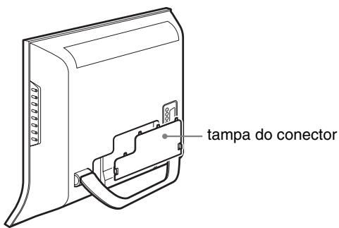
text_image
tampa do conectortext_image
tampa do conectornatural_image
Diagram showing a device being processed from a left-side view to an exploded view, with no visible text or symbols.Notas
text_image
Diagram showing hand cursor clicking and clicking a button with an arrow, indicating OK statustext_image
Diagram showing finger pressing and navigation icons with directional arrows and a 'OK' buttonSe ↩ for um dos itens de menu.
text_image
Diagram showing finger pressing and navigation buttons with directional arrows and a 'OK' button5 Fechar o menu.
text_image
↑ OK ↓ → ↑ OK ↓text_image
↑ OK ↓ → ↑ OK ↓Se ← for um dos itens de menu.
text_image
↑ OK ↓ → ↑ OK ↓5 Fechar o menu.
Os menus “Backlight,” “Contrast,” “Brightness,” “Color,” “Hue,”
text_image
Picture Mode: Vivid Backlight: Standard Contrast: ECO Brightness: Auto Color: 50 Hue: 0 Sharpness: 7 Color Temp.: Gamma: Picture Mode Reset NR: Off Dynamic Contrast: Off Select: OK Set: OK Exit: MENU■ Ajustar “Brightness”
Surge no ecrã o menu “Brightness”.
text_image
Picture DVI-D: PC 1 Mode: Backlight: Contrast: Brightness: Color: Hue: Sharpness: Color Temp. 9300K Gamma: Picture Mode Reset NR: Dynamic Contrast: Gamma1 Gamma2 Gamma3 Gamma4 1680 × 1050/60 Hz Select: OK Set: OK Exit: MENUtext_image
Picture DVI-D: PC 1 Mode: Backlight: Contrast: Brightness: Color: Hue: Sharpness: Color Temp.: Gamma: Picture Mode Reset OK Cancel NR: Dynamic Contrast: 1680 × 1050/60 Hz Select: OK Exit: MENUtext_image
Picture Mode: Vivid Backlight: 100 Contrast: 70 Brightness: 50 Color: 50 Hue: 0 Sharpness: 7 Color Temp: Gamma: Picture Mode Reset NR: On Dynamic Contrast: Off Select OK Set: OK Exit MENUtext_image
Picture Mode: Vivid Backlight: 100 Contrast: 70 Brightness: 50 Color: 50 Hue: 0 Sharpness: 7 Color Temp. Gamma: Picture Mode Reset NR: Off Dynamic Contrast: On Off Select: OK Set: OK Exit: MENU- Surround
- Treble
- Bass
• Balance - Auto Volume
- Dual Sound
- Audio Reset
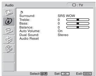
text_image
Audio Surround: SRS WOW Treble: 0 Bass: 0 Balance: 0 Auto Volume: On Dual Sound: Stereo Audio Reset Select: OK Set: OK Exit: MENU■ Definir "Surround"
text_image
Audio Surround: SRS WOW Treble: Off Bass: 0 Balance: 0 Auto Volume: On Dual Sound: Stereo Audio Reset Select: OK Set: OK Exit: MENU■ Ajustar “Treble,” “Bass,” e “Balance”
text_image
Audio Surround: SRS WOW Treble: 0 Bass: 0 Balance: 0 Auto Volume: On Dual Sound: Off Audio Reset Select: OK Exit: MENUtext_image
Audio Surround: SRS WOW Treble: 0 Bass: 0 Balance: 0 Auto Volume: On Dual Sound: Stereo Audio Reset A B Mono Select: OK Set: OK Exit: MENUtext_image
Audio Surround: SRS WOW Treble: 0 Bass: 0 Balance: 0 Auto Volume: On Dual Sound: Stereo Audio Reset OK Cancel Select: OK Set: OK Exit: MENU- Zoom
- Auto Adjust
- Phase
- Pitch
• H Center
• V Center - Resolution
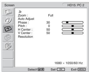
text_image
Screen HD15: PC 2 Zoom : Full Auto Adjust Phase : 30 Pitch : 0 H Center : 50 V Center : 50 Resolution 1680 × 1050/60 Hz Select OK Set: OK Exit: MENU■ Definir "Zoom"
text_image
Test Pattern F200text_image
+ - Volume 30text_image
Information DVI-D:PC1 Cable DisconnectedSe surgir no ecrã “Power will be turned off by off timer soon”
Se surgir no ecrã “Power will be turned off by auto shut off soon”
Se surgir no ecrã “Feature Not Available”
Horizontal: 28–68 kHz
Vertical: 60 Hz
Áudio:
Mini-ficha estéreo, 500 mVrms
PC 2
Formato de sinal:
RGB analógico (HD-15D-sub)
Horizontal: 28–86 kHz
480i (525i), 480p (525p), 576i (625i), 576p (625p),
720p (750p), 1080i (1125i)
Áudio:
100–240 V AC, 50–60 Hz
Máx. 1,2 A
Consumo de energia
LCD Multi Function Display
MFM-HT205
Owner's Record
The model and serial numbers are located at the rear of the unit. Record these numbers in the spaces provided below. Refer to them whenever you call upon your dealer regarding this product. Model No. ____ Serial No. ____
WARNING
To reduce the risk of fire or electric shock, do not expose this apparatus to rain or moisture.
Dangerously high voltages are present inside the unit. Do not open the cabinet. Refer servicing to qualified personnel only.
FCC Notice
This equipment has been tested and found to comply with the limits for a Class B digital device, pursuant to Part 15 of the FCC Rules. These limits are designed to provide reasonable protection against harmful interference in a residential installation. This equipment generates, uses, and can radiate radio frequency energy and, if not installed and used in accordance with the instructions, may cause harmful interference to radio communications. However, there is no guarantee that interference will not occur in a particular installation. If this equipment does cause harmful interference to radio or television reception, which can be determined by turning the equipment off and on, the user is encouraged to try to correct the interference by one or more of the following measures:
– Reorient or relocate the receiving antenna.
– Increase the separation between the equipment and receiver.
- Connect the equipment into an outlet on a circuit different from that to which the receiver is connected.
- Consult the dealer or an experienced radio/TV technician for help. You are cautioned that any changes or modifications not expressly approved in this manual could void your authority to operate this equipment.
IMPORTANTE
If you have any questions about this product, you may call; Sony Customer Information Services Center 1-800-222-7669 or http://www.sony.com/
Declaration of Conformity
Trade Name: SONY
Model: MFM-HT205
Responsible Party: Sony Electronics Inc.
Address: 16450 W. Bernardo Dr,
San Diego, CA 92127 U.S.A.
Telephone Number: 858-942-2230
This device complies with part 15 of the FCC rules. Operation is subject to the following two conditions: (1) This device may not cause harmful interference, and (2) this device must accept any interference received, including interference that may cause undesired operation.

BZ03
This notice is applicable for USA/Canada only.
If shipped to USA/Canada, install only a UL LISTED/CSA
LABELLED power supply cord meeting the following specifications:
SPECIFICATIONS
Plug Type Nema-Plug 5-15p
Cord Type SVT or SJT, minimum 3 × 18 AWG
Length Maximum 15 feet
Rating Minimum 7 A, 125 V
NOTICE
natural_image
Technical line drawing of a two-pin electrical plug with terminal connectors (no text or symbols)Содержание
natural_image
Technical line drawing of a mechanical component with a curved handle and mounting bracket (no text or symbols)Примечание
text_image
Diagram showing a no-rejection sign above a vehicle charging plug, indicating no leakage or no power.natural_image
Illustration of hands folding a folded document with a curved arrow indicating rotation (no text or symbols)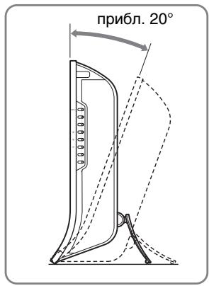
text_image
прибл. 20°natural_image
Diagram showing a device being processed from a component, with no visible text or symbols.Примечания
text_image
Diagram showing finger pressing and clicking icons with an 'OK' button, indicating press or click action.text_image
Diagram showing finger pressing and navigation icons with directional arrows and a 'OK' buttontext_image
Diagram showing hand cursor clicking and clicking a button with an arrow, indicating OK status5 Закройте меню.
text_image
↑ OK ↓ → ↑ OK ↓text_image
↑ OK ↓ → ↑ OK ↓text_image
↑ OK ↓ → ↑ OK ↓5 Закройте меню.
480i (525i), 480p (525p), 576i (625i), 576p (625p),
720p (750p), 1080i (1125i)
Звук:
LCD Multi Function Display
MFM-HT205
Owner's Record
The model and serial numbers are located at the rear of the unit. Record these numbers in the spaces provided below. Refer to them whenever you call upon your dealer regarding this product. Model No. ____ Serial No. ____
WARNING
To reduce the risk of fire or electric shock, do not expose this apparatus to rain or moisture.
Dangerously high voltages are present inside the unit. Do not open the cabinet. Refer servicing to qualified personnel only.
FCC Notice
This equipment has been tested and found to comply with the limits for a Class B digital device, pursuant to Part 15 of the FCC Rules. These limits are designed to provide reasonable protection against harmful interference in a residential installation. This equipment generates, uses, and can radiate radio frequency energy and, if not installed and used in accordance with the instructions, may cause harmful interference to radio communications. However, there is no guarantee that interference will not occur in a particular installation. If this equipment does cause harmful interference to radio or television reception, which can be determined by turning the equipment off and on, the user is encouraged to try to correct the interference by one or more of the following measures:
– Reorient or relocate the receiving antenna.
– Increase the separation between the equipment and receiver.
- Connect the equipment into an outlet on a circuit different from that to which the receiver is connected.
- Consult the dealer or an experienced radio/TV technician for help. You are cautioned that any changes or modifications not expressly approved in this manual could void your authority to operate this equipment.
IMPORTANTE
If you have any questions about this product, you may call; Sony Customer Information Services Center 1-800-222-7669 or http://www.sony.com/
Declaration of Conformity
Trade Name: SONY Model: MFM-HT205 Responsible Party: Sony Electronics Inc. Address: 16450 W. Bernardo Dr, San Diego, CA 92127 U.S.A. Telephone Number: 858-942-2230
This device complies with part 15 of the FCC rules. Operation is subject to the following two conditions: (1) This device may not cause harmful interference, and (2) this device must accept any interference received, including interference that may cause undesired operation.
NOTICE
This notice is applicable for USA/Canada only. If shipped to USA/Canada, install only a UL LISTED/CSA LABELLED power supply cord meeting the following specifications:
SPECIFICATIONS
Plug Type Nema-Plug 5-15p Cord Type SVT or SJT, minimum 3 × 18 AWG Length Maximum 15 feet Rating Minimum 7 A, 125 V
NOTICE
natural_image
Technical line drawing of a plug with three leads and a terminal connector (no text or symbols)Obsah
PIP On → PAP On → Off → PIP On...
11 Tlačítko (Picture Mode) (strana 33)
natural_image
Technical line drawing of a mechanical component with a curved base and lever mechanism (no text or symbols)Poznámka
text_image
Diagram showing a no-smoking sign above a vehicle seatbelt mechanism, indicating no smoking or no usage.natural_image
Diagram showing a device transitioning from a cylindrical component to a battery pack, with no visible text or symbols.Poznámky
text_image
MENU Picture DVI-D: PC 1 Mode: Backlight: Contrast: Brightness: Color: Hue: Sharpness: Color Temp: Gamma: Picture Mode Reset NR: Dynamic Contrast: 1680 × 1050/60 Hz Select: Set: OK Exit: MENU2 Vyberte nabídku.
text_image
Diagram showing finger pressing and navigation icons with directional arrows and a 'OK' buttontext_image
Diagram showing finger pressing and navigation icons with directional arrows and a 'OK' buttontext_image
Diagram showing finger pressing and navigation buttons with directional arrows and a 'OK' button5 Zavřete nabídku.
text_image
↑ OK ↓ → ↑ OK ↓text_image
↑ OK ↓ → ↑ OK ↓text_image
↑ OK ↓ → ↑ OK ↓5 Zavřete nabídku.
text_image
Picture DVI-D: PC 1 Mode: Movie Backlight: 100 Contrast: 70 Brightness: 50 Color: Hue: Sharpness: Color Temp: 9300K Gamma: Gamma4 Picture Mode Reset NR: Dynamic Contrast: 1680 × 1050/60 Hz Select Set: OK Exit: MENU- NR
- Dynamic Contrast
Tip
text_image
Picture Mode: Vivid Backlight: Standard Contrast: ECO Brightness: Auto Color: 50 Hue: 0 Sharpness: 7 Color Temp.: Gamma: Picture Mode Reset NR: Off Dynamic Contrast: Off Select: OK Exit: MENUtext_image
Picture DVI-D: PC 1 Mode: Backlight: Contrast: Brightness: Color: Hue: Sharpness: Color Temp.: Gamma: Picture Mode Reset OK NR: Dynamic Contrast: 1680 × 1050/60 Hz Select: Set: OK Exit: MENUtext_image
Picture Mode: Vivid Backlight: 100 Contrast: 70 Brightness: 50 Color: 50 Hue: 0 Sharpness: 7 Color Temp. Gamma: Picture Mode Reset NR: On Dynamic Contrast: Off Select OK Set: OK Exit: MENUtext_image
Picture Mode: Vivid Backlight: 100 Contrast: 70 Brightness: 50 Color: 50 Hue: 0 Sharpness: 7 Color Temp. Gamma: Picture Mode Reset NR: Off Dynamic Contrast: On Off Select: OK Set: OK Exit: MENU- Surround
- Treble
- Bass
• Balance - Auto Volume
- Dual Sound
- Audio Reset
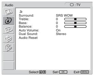
text_image
Audio Surround: SRS WOW Treble: 0 Bass: 0 Balance: 0 Auto Volume: On Dual Sound: Stereo Audio Reset Select: OK Exit: MENUtext_image
Audio Surround: SRS WOW Treble: Off Bass: 0 Balance: 0 Auto Volume: On Dual Sound: Stereo Audio Reset Select: OK Set: OK Exit: MENUtext_image
Audio Surround: SRS WOW Treble: 0 Bass: 0 Balance: 0 Auto Volume: On Dual Sound: Off Audio Reset Select: OK Set: OK Exit: MENUtext_image
Audio Surround: SRS WOW Treble: 0 Bass: 0 Balance: 0 Auto Volume: On Dual Sound: Stereo Audio Reset: A B Mono Select: OK Set: OK Exit: MENUtext_image
Audio Surround: SRS WOW Treble: 0 Bass: 0 Balance: 0 Auto Volume: On Dual Sound: Stereo Audio Reset OK Cancel Select Set: OK Exit: MENU- Zoom
- Auto Adjust
- Phase
- Pitch
• H Center
• V Center - Resolution
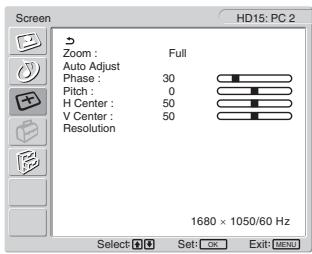
text_image
Screen HD15: PC 2 Zoom : Full Auto Adjust Phase : 30 Pitch : 0 H Center : 50 V Center : 50 Resolution 1680 × 1050/60 Hz Select Set: OK Exit: MENUNastavení „Zoom“
text_image
Test Pattern STG Test Pattern STGtext_image
+ → Volume 30text_image
Information DVI-D:PCI Cable DisconnectedPokud se na obrazovce objeví „Power will be turned off by off timer soon“
480i (525i), 480p (525p), 576i (625i), 576p (625p),
720p (750p), 1080i (1125i)
Zvuk:
phono konektor (stereo), 500 mVrms
VIDEO 1
Standard signálu:
100–240 V AC, 50–60 Hz
Max. 1,2 A
LCD Multi Function Display
MFM-HT205
Owner's Record
The model and serial numbers are located at the rear of the unit. Record these numbers in the spaces provided below. Refer to them whenever you call upon your dealer regarding this product. Model No. ____ Serial No. ____
WARNING
To reduce the risk of fire or electric shock, do not expose this apparatus to rain or moisture.
Dangerously high voltages are present inside the unit. Do not open the cabinet. Refer servicing to qualified personnel only.
FCC Notice
This equipment has been tested and found to comply with the limits for a Class B digital device, pursuant to Part 15 of the FCC Rules. These limits are designed to provide reasonable protection against harmful interference in a residential installation. This equipment generates, uses, and can radiate radio frequency energy and, if not installed and used in accordance with the instructions, may cause harmful interference to radio communications. However, there is no guarantee that interference will not occur in a particular installation. If this equipment does cause harmful interference to radio or television reception, which can be determined by turning the equipment off and on, the user is encouraged to try to correct the interference by one or more of the following measures:
– Reorient or relocate the receiving antenna.
– Increase the separation between the equipment and receiver.
- Connect the equipment into an outlet on a circuit different from that to which the receiver is connected.
- Consult the dealer or an experienced radio/TV technician for help. You are cautioned that any changes or modifications not expressly approved in this manual could void your authority to operate this equipment.
IMPORTANTE
If you have any questions about this product, you may call; Sony Customer Information Services Center 1-800-222-7669 or http://www.sony.com/
Declaration of Conformity
Trade Name: SONY Model: MFM-HT205 Responsible Party: Sony Electronics Inc. Address: 16450 W. Bernardo Dr, San Diego, CA 92127 U.S.A. Telephone Number: 858-942-2230
This device complies with part 15 of the FCC rules. Operation is subject to the following two conditions: (1) This device may not cause harmful interference, and (2) this device must accept any interference received, including interference that may cause undesired operation.
NOTICE
This notice is applicable for USA/Canada only. If shipped to USA/Canada, install only a UL LISTED/CSA LABELLED power supply cord meeting the following specifications:
SPECIFICATIONS
Plug Type Nema-Plug 5-15p Cord Type SVT or SJT, minimum 3 × 18 AWG Length Maximum 15 feet Rating Minimum 7 A, 125 V
NOTICE
natural_image
Technical line drawing of a plug with three leads and a terminal connector (no text or symbols)Tartalomjegyzék
Óvintézkedések 5
natural_image
Three line drawings of different types of electrical plugs (no text or symbols)natural_image
Technical line drawing of a mechanical component with a curved base and lever mechanism (no text or symbols)Megjegyzés
text_image
Diagram showing a no-rejection barrier symbol above a vehicle seatbelt mechanismnatural_image
Diagram showing a device component before and after assembly, with no visible text or symbolsMegjegyzések
text_image
Diagram showing finger pressing and clicking icons with an 'OK' button, indicating press or click action.text_image
Diagram showing finger pressing and navigation icons with directional arrows and a 'OK' buttontext_image
Diagram showing finger pressing and clicking icons with a right-pointing arrow labeled 'OK'5 Lépjen ki a menüböl.
text_image
↑ OK ↓ → ↑ OK ↓text_image
↑ OK ↓ → ↑ OK ↓text_image
↑ OK ↓ → ↑ OK ↓5 Lépjen ki a menüböl.
text_image
Picture DVI-D: PC 1 Mode: Movie Backlight: 100 Contrast: 70 Brightness: 50 Color: Hue: Sharpness: Color Temp: 9300K Gamma: Gamma4 Picture Mode Reset NR: Dynamic Contrast: 1680 × 1050/60 Hz Select Set: OK Exit MENU- NR
- Dynamic Contrast
Hasznos tudnivaló
text_image
Picture DVI-D: PC 1 Mode: Game Backlight: Movie Contrast: PC Brightness: Auto Color: Hue: Sharpness: Color Temp.: 9300K Gamma: Gamma4 Picture Mode Reset NR: Dynamic Contrast: 1680 × 1050/60 Hz Select: OK Set: OK Exit: MENUtext_image
Picture Mode: Vivid Backlight: Standard Contrast: ECO Brightness: Auto Color: 50 Hue: 0 Sharpness: 7 Color Temp.: Gamma: Picture Mode Reset NR: Off Dynamic Contrast: Off Select: OK Exit: MENUtext_image
Picture DVI-D: PC 1 Mode: Backlight: Contrast: Brightness: Color: Hue: Sharpness: Color Temp: Gamma: Picture Mode Reset NR: Dynamic Contrast: Movie 100 70 50 9300K 6500K sRGB User L Adjust 1680 × 1050/60 Hz Select Set: OK Exit: MENUtext_image
Picture DVI-D: PC 1 Mode: Backlight: Contrast: Brightness: Color: Hue: Sharpness: Color Temp: 9300K Gamma: Picture Mode Reset NR: Dynamic Contrast: Gamma1 Gamma2 Gamma3 Gamma4 1680 × 1050/60 Hz Select: OK Set: OK Exit: MENUtext_image
Picture DVI-D: PC 1 Mode: Backlight: Contrast: Brightness: Color: Hue: Sharpness: Color Temp.: Gamma: Picture Mode Reset OK NR: Cancel Dynamic Contrast: 1680 × 1050/60 Hz Select Set: OK Exit: MENUtext_image
Picture Mode: Vivid Backlight: 100 Contrast: 70 Brightness: 50 Color: 50 Hue: 0 Sharpness: 7 Color: Temp. Gamma: Picture Mode Reset NR: On Dynamic Contrast: Off Select Set OK Exit MENUtext_image
Picture Mode: Vivid Backlight: 100 Contrast: 70 Brightness: 50 Color: 50 Hue: 0 Sharpness: 7 Color: Temp. Gamma: Picture Mode Reset NR: Off Dynamic Contrast: On Off Select OK Set: OK Exit: MENU- Surround
- Treble
- Bass
• Balance - Auto Volume
- Dual Sound
- Audio Mode Reset
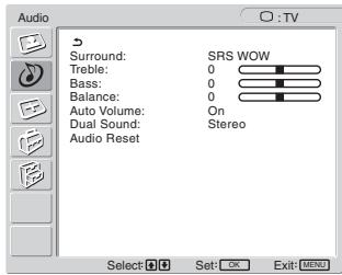
text_image
Audio Surround: SRS WOW Treble: 0 Bass: 0 Balance: 0 Auto Volume: On Dual Sound: Stereo Audio Reset Select OK Set: OK Exit: MENUtext_image
Audio Surround: SRS WOW Treble: Off Bass: 0 Balance: 0 Auto Volume: On Dual Sound: Stereo Audio Reset Select: OK Exit: MENUtext_image
Audio Surround: SRS WOW Treble: 0 Bass: 0 Balance: 0 Auto Volume: On Dual Sound: Off Audio Reset Select: OK Exit: MENUtext_image
Audio Surround: SRS WOW Treble: 0 Bass: 0 Balance: 0 Auto Volume: On Dual Sound: Stereo Audio Reset: A B Mono Select: OK Set: OK Exit: MENUtext_image
Audio Surround: SRS WOW Treble: 0 Bass: 0 Balance: 0 Auto Volume: On Dual Sound: Stereo Audio Reset OK Cancel Select Set: OK Exit: MENU- Zoom
- Auto Adjust
- Phase
- Pitch
• H Center
• V Center - Resolution

text_image
Screen Zoom : Full Auto Adjust Phase : 30 Pitch : 0 H Center : 50 V Center : 50 Resolution 1680 × 1050/60 Hz Select OK Exit MENU HD15: PC 2Képméret-beállítás
text_image
+ - Volume 30text_image
Information DVI-D:PCI Cable DisconnectedD/K: R1...R12, R21...R69
L: F2...F10, B-Q, F21...F69
I: UHF B21...B69
Antenna:
480i (525i), 480p (525p), 576i (625i), 576p (625p),
720p (750p), 1080i (1125i)
Audio:
100–240 V AC, 50–60 Hz
Max. 1,2 A
LCD Multi Function Display
MFM-HT205
Owner's Record
The model and serial numbers are located at the rear of the unit. Record these numbers in the spaces provided below. Refer to them whenever you call upon your dealer regarding this product. Model No. ____ Serial No. ____
WARNING
To reduce the risk of fire or electric shock, do not expose this apparatus to rain or moisture.
Dangerously high voltages are present inside the unit. Do not open the cabinet. Refer servicing to qualified personnel only.
FCC Notice
This equipment has been tested and found to comply with the limits for a Class B digital device, pursuant to Part 15 of the FCC Rules. These limits are designed to provide reasonable protection against harmful interference in a residential installation. This equipment generates, uses, and can radiate radio frequency energy and, if not installed and used in accordance with the instructions, may cause harmful interference to radio communications. However, there is no guarantee that interference will not occur in a particular installation. If this equipment does cause harmful interference to radio or television reception, which can be determined by turning the equipment off and on, the user is encouraged to try to correct the interference by one or more of the following measures:
– Reorient or relocate the receiving antenna.
– Increase the separation between the equipment and receiver.
- Connect the equipment into an outlet on a circuit different from that to which the receiver is connected.
- Consult the dealer or an experienced radio/TV technician for help. You are cautioned that any changes or modifications not expressly approved in this manual could void your authority to operate this equipment.
IMPORTANTE
If you have any questions about this product, you may call; Sony Customer Information Services Center 1-800-222-7669 or http://www.sony.com/
Declaration of Conformity
Trade Name: SONY Model: MFM-HT205 Responsible Party: Sony Electronics Inc. Address: 16450 W. Bernardo Dr, San Diego, CA 92127 U.S.A. Telephone Number: 858-942-2230
This device complies with part 15 of the FCC rules. Operation is subject to the following two conditions: (1) This device may not cause harmful interference, and (2) this device must accept any interference received, including interference that may cause undesired operation.
NOTICE
This notice is applicable for USA/Canada only. If shipped to USA/Canada, install only a UL LISTED/CSA LABELLED power supply cord meeting the following specifications:
SPECIFICATIONS
Plug Type Nema-Plug 5-15p Cord Type SVT or SJT, minimum 3 × 18 AWG Length Maximum 15 feet Rating Minimum 7 A, 125 V
NOTICE
natural_image
Technical line drawing of a plug with three leads and a terminal connector (no text or symbols)Spis treści
text_image
ZERO (BOLEC OCHRONNY) ZERO FAZAnatural_image
Technical line drawing of a mechanical component with a lever and base plate (no text or symbols)Uwaga
text_image
Diagram showing a no-smoking sign above a vehicle seatbelt with cable routing, indicating no smoking or no usage.text_image
Technical diagram showing two views of a folding or folding device with angular measurement annotation 'ok. 20°'natural_image
Diagram showing a device component before and after assembly, with no visible text or symbolsUwaga
text_image
Diagram showing finger pressing and navigation buttons with directional arrows and a 'OK' buttontext_image
Diagram showing finger pressing and navigation icons with directional arrows and a 'OK' buttontext_image
Diagram showing finger pressing and navigation icons with directional arrows and a 'OK' button5 Zamknij menu.
text_image
↑ OK ↓ → ↑ OK ↓text_image
↑ OK ↓ → ↑ OK ↓text_image
↑ OK ↓ → ↑ OK ↓5 Zamknij menu.
text_image
Picture Mode: Vivid Backlight: Standard Contrast: ECO Brightness: Auto Color: 50 Hue: 0 Sharpness: 7 Color Temp. Gamma: Picture Mode Reset NR: Off Dynamic Contrast: Off Select OK Set: OK Exit: MENUtext_image
Picture DVI-D: PC 1 Mode: Backlight: Contrast: Brightness: Color: Hue: Sharpness: Color Temp: Gamma: Picture Mode Reset NR: Dynamic Contrast: Movie 100 70 50 9300K 6500K sRGB User L Adjust 1680 × 1050/60 Hz Select Set: OK Exit: MENUtext_image
Picture DVI-D: PC 1 Mode: Movie Backlight: 100 Contrast: 70 Brightness: 50 Color: Hue: Sharpness: Color Temp.: 9300K Gamma: Gamma4 Picture Mode Reset OK NR: Cancel Dynamic Contrast: 1680 × 1050/60 Hz Select Set: OK Exit: Nonetext_image
Picture Mode: Vivid Backlight: 100 Contrast: 70 Brightness: 50 Color: 50 Hue: 0 Sharpness: 7 Color: Temp. Gamma: Picture Mode Reset NR: On Dynamic Contrast: Off Select Set: OK Exit: MENUtext_image
Picture Mode: Vivid Backlight: 100 Contrast: 70 Brightness: 50 Color: 50 Hue: 0 Sharpness: 7 Color Temp.: Gamma: Picture Mode Reset NR: Off Dynamic Contrast: On Off Select Set: OK Exit: MENU- Surround
- Treble
- Bass
• Balance - Auto Volume
- Dual Sound
- Audio Reset
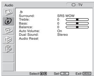
text_image
Audio Surround: SRS WOW Treble: 0 Bass: 0 Balance: 0 Auto Volume: On Dual Sound: Stereo Audio Reset Select Set: OK Exit MENUtext_image
Audio Surround: SRS WOW Treble: Off Bass: 0 Balance: 0 Auto Volume: On Dual Sound: Stereo Audio Reset Select: Set: OK Exit: MENUtext_image
Audio Surround: SRS WOW Treble: 0 Bass: 0 Balance: 0 Auto Volume: On Dual Sound: Off Audio Reset Select OK Exit MENUtext_image
Audio Surround: SRS WOW Treble: 0 Bass: 0 Balance: 0 Auto Volume: On Dual Sound: Stereo Audio Reset: A B Mono Select: OK Set: OK Exit: MENUtext_image
Audio Surround: SRS WOW Treble: 0 Bass: 0 Balance: 0 Auto Volume: On Dual Sound: Stereo Audio Reset OK Cancel Select OK Set: OK Exit MENU- Zoom
- Auto Adjust
- Phase
- Pitch
• H Center
• V Center - Resolution
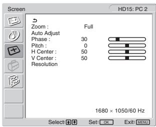
text_image
Screen HD15: PC 2 Zoom : Full Auto Adjust Phase : 30 Pitch : 0 H Center : 50 V Center : 50 Resolution 1680 x 1050/60 Hz Select: OK Set: OK Exit: MENUtext_image
Test Pattern INSNtext_image
+ - Volume 30text_image
Information DVI-D:PC1 Cable DisconnectedLCD Multi Function Display
MFM-HT205
Owner's Record
The model and serial numbers are located at the rear of the unit. Record these numbers in the spaces provided below. Refer to them whenever you call upon your dealer regarding this product. Model No. ____ Serial No. ____
WARNING
To reduce the risk of fire or electric shock, do not expose this apparatus to rain or moisture.
Dangerously high voltages are present inside the unit. Do not open the cabinet. Refer servicing to qualified personnel only.
FCC Notice
This equipment has been tested and found to comply with the limits for a Class B digital device, pursuant to Part 15 of the FCC Rules. These limits are designed to provide reasonable protection against harmful interference in a residential installation. This equipment generates, uses, and can radiate radio frequency energy and, if not installed and used in accordance with the instructions, may cause harmful interference to radio communications. However, there is no guarantee that interference will not occur in a particular installation. If this equipment does cause harmful interference to radio or television reception, which can be determined by turning the equipment off and on, the user is encouraged to try to correct the interference by one or more of the following measures:
– Reorient or relocate the receiving antenna.
– Increase the separation between the equipment and receiver.
- Connect the equipment into an outlet on a circuit different from that to which the receiver is connected.
- Consult the dealer or an experienced radio/TV technician for help. You are cautioned that any changes or modifications not expressly approved in this manual could void your authority to operate this equipment.
IMPORTANTE
If you have any questions about this product, you may call; Sony Customer Information Services Center 1-800-222-7669 or http://www.sony.com/
Declaration of Conformity
Trade Name: SONY Model: MFM-HT205 Responsible Party: Sony Electronics Inc. Address: 16450 W. Bernardo Dr, San Diego, CA 92127 U.S.A. Telephone Number: 858-942-2230
This device complies with part 15 of the FCC rules. Operation is subject to the following two conditions: (1) This device may not cause harmful interference, and (2) this device must accept any interference received, including interference that may cause undesired operation.
NOTICE
This notice is applicable for USA/Canada only. If shipped to USA/Canada, install only a UL LISTED/CSA LABELLED power supply cord meeting the following specifications:
SPECIFICATIONS
Plug Type Nema-Plug 5-15p Cord Type SVT or SJT, minimum 3 × 18 AWG Length Maximum 15 feet Rating Minimum 7 A, 125 V
NOTICE
natural_image
Technical line drawing of a plug with three leads and a terminal connector (no text or symbols)Kazalo
Varnostna opozorila .... 5
Deli monitorja in elementi za nastavljanje 6
Namestitev....10
Nastavitev 1: Uporabite podstavek ..... 10
Nastavitev 2: Priklop kablov ....10
PIP On → PAP On → Off → PIP On...
11 Gumb ⚙ (slikovni meni) (stran 33)
11 Gumbi ↑/↓ in OK (stran 19)
Pritisnite gumba ↑/↓ za izbor možnosti v meniju ter za nastavitve.
natural_image
Technical line drawing of a mechanical component with a curved base and lever mechanism (no text or symbols)Opozorilo
text_image
Diagram showing a no-smoking symbol above a vehicle seatbelt device, indicating restricted use or absence of usage.natural_image
Diagram showing a device being processed from a left-side view to a right-side view, with no visible text or symbols.Opozorilo
text_image
Diagram showing finger pressing and clicking control buttons with directional arrows and a 'OK' button3 Izberite možnost, ki jo želite nastaviti.
Pritisnite ↑/↓ gumba za izbiro možnost, ki jo želite nastaviti, potem pa pritisnite OK gumb.
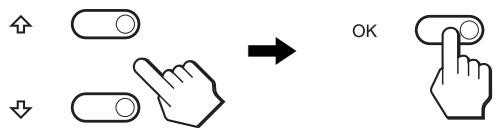
text_image
Diagram showing finger pressing and clicking icons with an 'OK' button, indicating press or navigation control.text_image
Diagram showing finger pressing and clicking icons with directional arrows, ending with 'OK' button5 Zaprite meni.
Z enkratnim pritiskom na gumb MENU se vrnete v normalni prikaz. Če gumba ne pritisnete, se meni po približno 45 sekundah zapre sam.

text_image
↑ OK ↓ → ↑ OK ↓3 Izberite možnost, ki jo želite nastaviti.
Pritisnite ↑/↓ gumba za izbiro možnosti, ki jo želite nastaviti, potem pa pritisnite OK gumb.
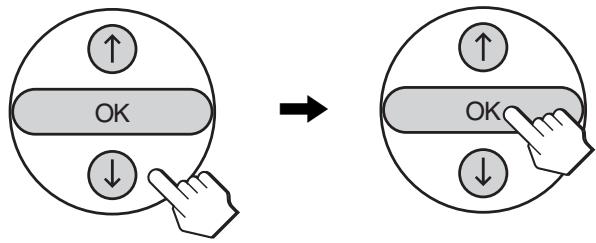
text_image
↑ OK ↓ → ↑ OK ↓text_image
↑ OK ↓ → ↑ OK ↓5 Zaprite meni.
Z enkratnim pritiskom na gumb MENU se vrnete v normalni prikaz. Če gumba ne pritisnete, se meni po približno 45 sekundah zapre sam.

text_image
Picture DVI-D: PC 1 Mode: Backlight: Contrast: Brightness: Color: Hue: Sharpness: Color Temp.: Gamma: Picture Mode Reset NR: Dynamic Contrast: Game Movie PC Auto 9300K Gamma4 1680 × 1050/60 Hz Select: OK Set: OK Exit: MENU4 Pritiskajte gumba ↑/↓ za izbiro želenega načina in pritisnite OK gumb.
text_image
Picture Mode: Vivid Backlight: Standard Contrast: ECO Brightness: Auto Color: 50 Hue: 0 Sharpness: 7 Color Temp.: Gamma: Picture Mode Reset NR: Off Dynamic Contrast: Off Select: OK Set: OK Exit: MENU4 Pritiskajte gumba ↑/↓ za izbiro želenega načina in pritisnite OK gumb.
text_image
Picture DVI-D: PC 1 Mode: Backlight: Contrast: Brightness: Color: Hue: Sharpness: Color Temp: Gamma: Picture Mode Reset OK NR: Dynamic Contrast: 1680 × 1050/60 Hz Select: Set: OK Exit: MENU4 Pritiskajte gumba ↑/↓ za izbiro želenega načina in pritisnite OK gumb.
text_image
Picture Mode: Vivid Backlight: 100 Contrast: 70 Brightness: 50 Color: 50 Hue: 0 Sharpness: 7 Color Temp. Gamma: Picture Mode Reset NR: On Dynamic Contrast: Off Select OK Set: OK Exit: MENUtext_image
Picture Mode: Vivid Backlight: 100 Contrast: 70 Brightness: 50 Color: 50 Hue: 0 Sharpness: 7 Color Temp. Gamma: Picture Mode Reset NR: Off Dynamic Contrast: On Off Select: OK Set: OK Exit: MENUtext_image
Audio Surround: SRS WOW Treble: 0 Bass: 0 Balance: 0 Auto Volume: On Dual Sound: Stereo Audio Reset Select: OK Set: Export: MENUtext_image
Audio Surround: SRS WOW Treble: Off Bass: 0 Balance: 0 Auto Volume: On Dual Sound: Stereo Audio Reset Select: OK Sat: OK Exit: MENU4 Pritiskajte gumba ↑/↓ za izbiro želenega načina in pritisnite OK gumb.
text_image
Audio Surround: SRS WOW Treble: 0 Bass: 0 Balance: 0 Auto Volume: On Dual Sound: Off Audio Reset Select: OK Exit: MENUtext_image
Audio Surround: SRS WOW Treble: 0 Bass: 0 Balance: 0 Auto Volume: On Dual Sound: Stereo Audio Reset: A B Mono Select: OK Set: OK Exit: MENUtext_image
Audio Surround: SRS WOW Treble: 0 Bass: 0 Balance: 0 Auto Volume: On Dual Sounds: Stereo Audio Reset OK Cancel Select: OK Set: OK Exit: MENU- Zoom
- Auto Adjust
- Phase
- Pitch
• H Center
• V Center - Resolution
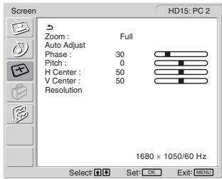
text_image
Screen Zoom : Full Auto Adjust Phase : 30 Pitch : 0 H Center : 50 V Center : 50 Resolution 1680 × 1050/60 Hz Select OK Exit MENU HD15: PC 2text_image
+ - Volume 302 Pritisnite gumba ▲+/- za nastavljanje želene stopnje glasnosti.
Lestvica jakosti po 5 sekundah samodejno izgine.
Opozorilo
text_image
Information DVI-D:PCI Cable DisconnectedČe se na zaslonu pojavi »Power will be turned off by off timer soon«
480i (525i), 480p (525p), 576i (625i), 576p (625p),
720p (750p), 1080i (1125i)
Zvok:
Phono vhod (stereo), 500 mVrms
VIDEO 1
Standard signala:
21-pinski priključek scart (standard CENELEC)
z vhodom AVDIO/VIDEO, izhodom RGB in izhodom TV AVDIO/VIDEO
VIDEO 2
Standard signala:
100–240 V AC, 50–60 Hz
Največ 1,2 A
Poraba
LCD Multi Function Display
MFM-HT205
Owner's Record
The model and serial numbers are located at the rear of the unit. Record these numbers in the spaces provided below. Refer to them whenever you call upon your dealer regarding this product. Model No. ____ Serial No. ____
WARNING
To reduce the risk of fire or electric shock, do not expose this apparatus to rain or moisture.
Dangerously high voltages are present inside the unit. Do not open the cabinet. Refer servicing to qualified personnel only.
FCC Notice
This equipment has been tested and found to comply with the limits for a Class B digital device, pursuant to Part 15 of the FCC Rules. These limits are designed to provide reasonable protection against harmful interference in a residential installation. This equipment generates, uses, and can radiate radio frequency energy and, if not installed and used in accordance with the instructions, may cause harmful interference to radio communications. However, there is no guarantee that interference will not occur in a particular installation. If this equipment does cause harmful interference to radio or television reception, which can be determined by turning the equipment off and on, the user is encouraged to try to correct the interference by one or more of the following measures:
– Reorient or relocate the receiving antenna.
– Increase the separation between the equipment and receiver.
- Connect the equipment into an outlet on a circuit different from that to which the receiver is connected.
- Consult the dealer or an experienced radio/TV technician for help. You are cautioned that any changes or modifications not expressly approved in this manual could void your authority to operate this equipment.
IMPORTANTE
If you have any questions about this product, you may call; Sony Customer Information Services Center 1-800-222-7669 or http://www.sony.com/
Declaration of Conformity
Trade Name: SONY Model: MFM-HT205 Responsible Party: Sony Electronics Inc. Address: 16450 W. Bernardo Dr, San Diego, CA 92127 U.S.A. Telephone Number: 858-942-2230
This device complies with part 15 of the FCC rules. Operation is subject to the following two conditions: (1) This device may not cause harmful interference, and (2) this device must accept any interference received, including interference that may cause undesired operation.
NOTICE
This notice is applicable for USA/Canada only. If shipped to USA/Canada, install only a UL LISTED/CSA LABELLED power supply cord meeting the following specifications:
SPECIFICATIONS
Plug Type Nema-Plug 5-15p Cord Type SVT or SJT, minimum 3 × 18 AWG Length Maximum 15 feet Rating Minimum 7 A, 125 V
NOTICE
natural_image
Technical line drawing of a three-pin electrical plug with terminal connectors (no text or symbols)İçindekiler
Uyarılar 5
“Brightness” Ayarlama 21
“Treble,” “Bass,” ve “Balance” Ayarlama ..... 25
PIP On → PAP On → Off → PIP On...
natural_image
Technical line drawing of a mechanical component with a curved handle and mounting bracket (no text or symbols)Not
text_image
Diagram showing a no-smoking symbol above a vehicle seatbelt device, indicating restricted use or absence of usage.text_image
yeshil yanar SONYnatural_image
Diagram showing a device being processed from a left-side view to a right-side view, with no visible text or symbols.Notlar
text_image
1 2 3 4 5 6 7 8 9 0 ENT PROG veyaip uçları
text_image
Diagram showing finger pressing and clicking control buttons with directional arrows and a 'OK' buttontext_image
Diagram showing finger pressing and clicking icons with an 'OK' button, indicating press or navigation control.text_image
Diagram showing finger pressing and clicking icons with an 'OK' button, indicating press or navigation control.5 Menüyü kapatma.
text_image
↑ OK ↓ → ↑ OK ↓text_image
↑ OK ↓ → ↑ OK ↓text_image
↑ OK ↓ → ↑ OK ↓5 Menüyü kapatma.
“Backlight,” “Contrast,” “Brightness,” “Color,” “Hue,”
text_image
Picture DVI-D: PC 1 Mode: Game Backlight: Movie Contrast: PC Brightness: Auto Color: Hue: Sharpness: Color Temp.: 9300K Gamma: Gamma4 Picture Mode Reset NR: Dynamic Contrast: 1680 × 1050/60 Hz Select: OK Set: OK Exit: Nonetext_image
Picture Mode: Vivid Backlight: Standard Contrast: ECO Brightness: Auto Color: 50 Hue: 0 Sharpness: 7 Color Temp.: Gamma: Picture Mode Reset NR: Off Dynamic Contrast: Off Select: OK Set: OK Exit: MENUtext_image
Picture DVI-D: PC 1 Mode: Backlight: Contrast: Brightness: Color: Hue: Sharpness: Color Temp: Gamma: Picture Mode Reset NR: Dynamic Contrast: Movie 100 70 50 9300K 6500K sRGB User LAdjust 1680 × 1050/60 Hz Select: Set: L OK Exit: MENUtext_image
Picture DVI-D: PC 1 Mode: Backlight: Contrast: Brightness: Color: Hue: Sharpness: Color Temp.: Gamma: Picture Mode Reset OK NR: Dynamic Contrast: 1680 × 1050/60 Hz Select: OK Set: OK Exit: [MENU]text_image
Picture Mode: Vivid Backlight: 100 Contrast: 70 Brightness: 50 Color: 50 Hue: 0 Sharpness: 7 Color Temp. Gamma: Picture Mode Reset NR: On Dynamic Contrast: Off Select Set: OK Exit: MENUtext_image
Picture Mode: Vivid Backlight: 100 Contrast: 70 Brightness: 50 Color: 50 Hue: 0 Sharpness: 7 Color Temp. Gamma: Picture Mode Reset NR: Off Dynamic Contrast: On Off Select: OK Exit: MENU- Surround
- Treble
- Bass
• Balance - Auto Volume
- Dual Sound
- Audio Reset
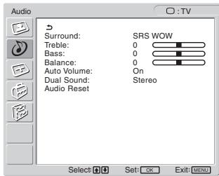
text_image
Audio Surround: SRS WOW Treble: 0 Bass: 0 Balance: 0 Auto Volume: On Dual Sound: Stereo Audio Reset Select Set: OK Exit: MENU■ "Surround" Ayarı
text_image
Audio Surround: SRS WOW Treble: Off Bass: 0 Balance: 0 Auto Volume: On Dual Sound: Stereo Audio Reset Select: OK Set: OK Exit: MENU■ “Treble,” “Bass,” ve “Balance” Ayarlama
text_image
Audio Surround: SRS WOW Treble: 0 Bass: 0 Balance: 0 Auto Volume: On Dual Sound: Off Audio Reset Select: OK Set: OK Exit: MENUtext_image
Audio Surround: SRS WOW Treble: 0 Bass: 0 Balance: 0 Auto Volume: On Dual Sound: Stereo Audio Reset: A B Mono Select Set: OK Exit: MENUtext_image
Audio Surround: SRS WOW Treble: 0 Bass: 0 Balance: 0 Auto Volume: On Dual Sound: Stereo Audio Reset OK Cancel Select Set: OK Exit MENU- Zoom
- Auto Adjust
- Phase
- Pitch
• H Center
• V Center - Resolution
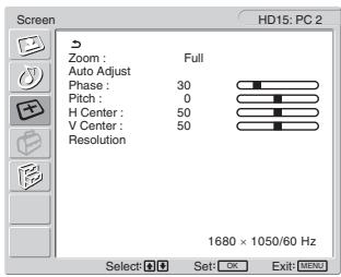
text_image
Screen HD15: PC 2 Zoom : Full Auto Adjust Phase : 30 Pitch : 0 H Center : 50 V Center : 50 Resolution 1680 × 1050/60 Hz Select: Set: OK Exit: MENU■ "Zoom" Ayarı
text_image
+ - Volume 30text_image
Information DVI-D:PC1 Cable DisconnectedEğer “Power will be turned off by off timer soon” ekranda görüntülenirse
Eğer “Power will be turned off by auto shut off soon” ekranda görüntülenirse
100–240 V AC, 50–60 Hz
Maks. 1,2 A
Güç tüketimi