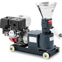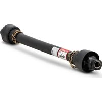
Wiesenfield WIE-PTO-141 - Agricultural mechanical part

WIE-PTO-141 - Agricultural mechanical part Wiesenfield - Free user manual and instructions

Find the device manual for free WIE-PTO-141 Wiesenfield in PDF.

📄 297 pages English EN Download 💬 AI Question 10 questions ⚙️ Specs
Notice Wiesenfield WIE-PTO-141 - page 17
Pick your language and provide your email: we'll send you a specifically translated version.
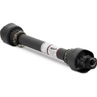
Product type Power Take-Off (PTO) shaft
Brand Wiesenfield
Model WIE-PTO-141
Length (retracted/extended) 101 cm / 141 cm
Weight 10,38 kg
Tube material Steel
Protection Plastic covers
Cardan type Telescopic
Main function Power transmission from tractor to agricultural implement
Safety devices Friction torque limiter, shear bolt clutch
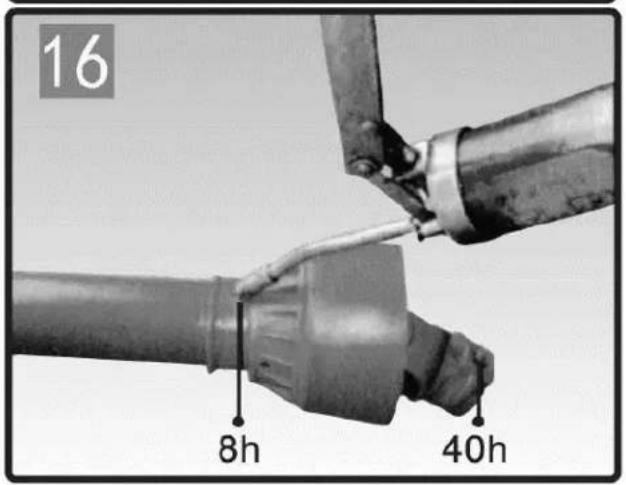
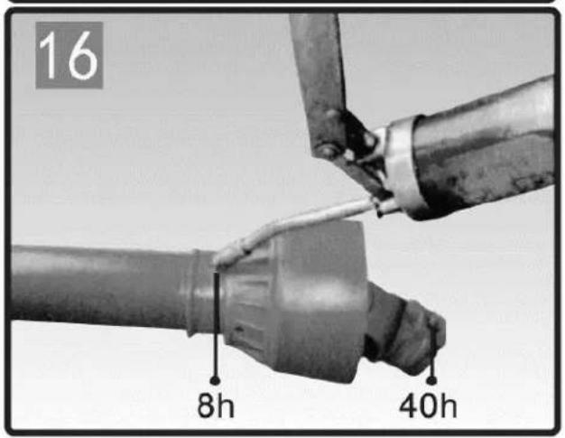
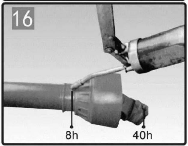
Lubrication Every 50 hours of use, all moving parts
Maintenance Regular cleaning, greasing of splines and joints
Attachment Pin or clamp depending on the shaft
Operating angle Equal and minimal angles between tractor and implement
Min. overlap 1/3 of tube length
Compatibility With standard splined shafts
Shortening possible Yes, by cutting tubes and covers
Application area Agriculture, gardening

Frequently Asked Questions - WIE-PTO-141 Wiesenfield

How to properly install the WIE-PTO-141 PTO shaft?
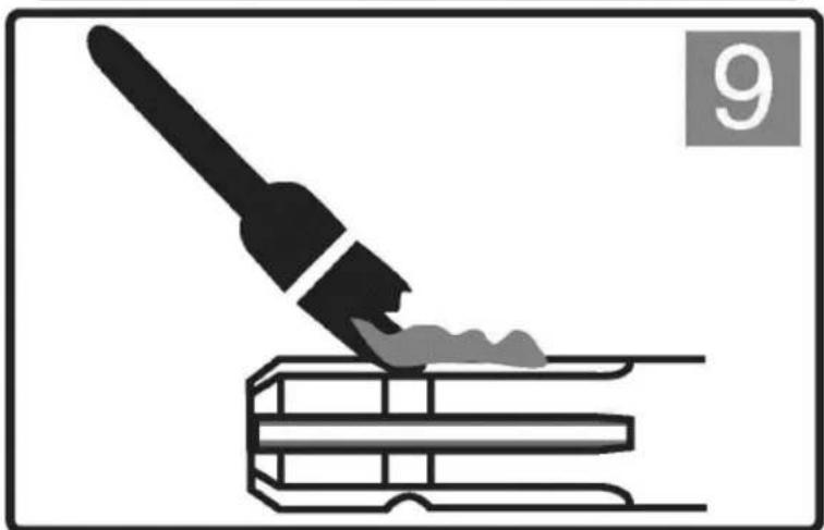
Ensure the tractor is stopped and the key removed. Clean and grease the splines. Push the pin and slide the yoke onto the tractor's PTO shaft until the pin engages in the groove. For the other end, slide the collar into open position, insert the yoke onto the implement's splined shaft, then release the collar. Check that both ends are securely attached.
What is the lubrication procedure and how often?
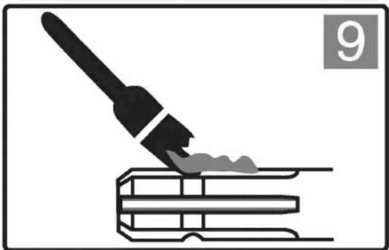
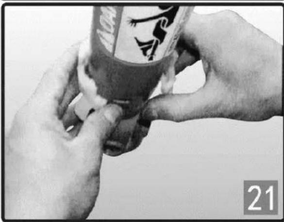
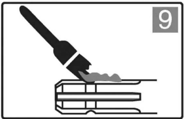
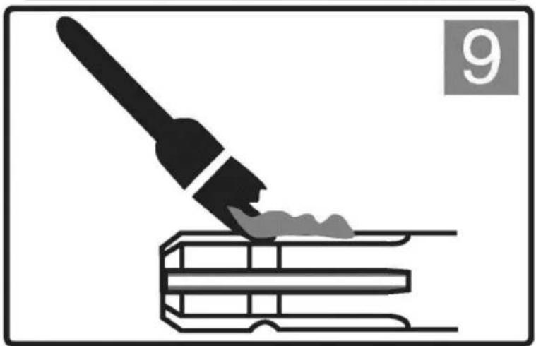
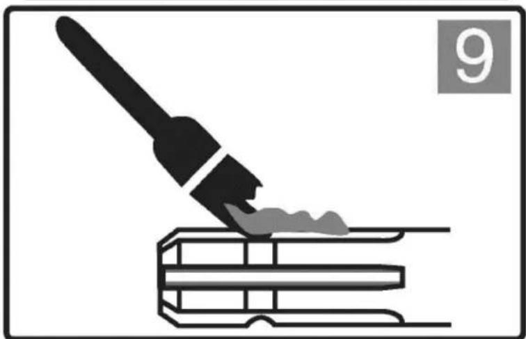
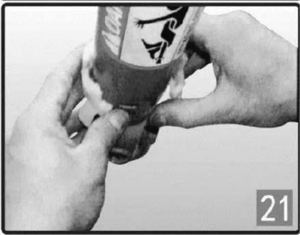
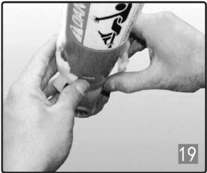
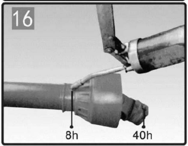
Lubricate all moving parts (joints, splines) every 50 hours of use and after storage. Use a suitable grease. Disassemble the tubes, remove the nylon bearings, grease the slots, then reassemble. See the manual diagram for specific points.
Can I shorten my PTO shaft?
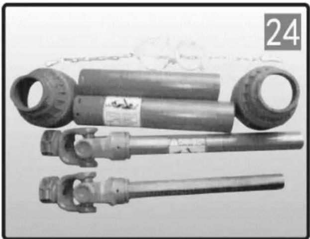
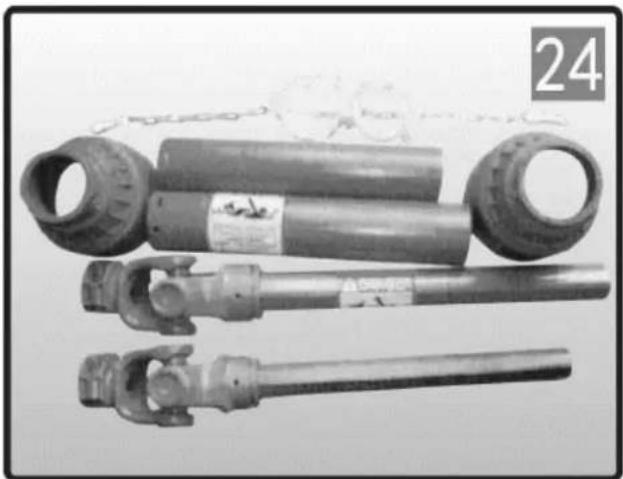
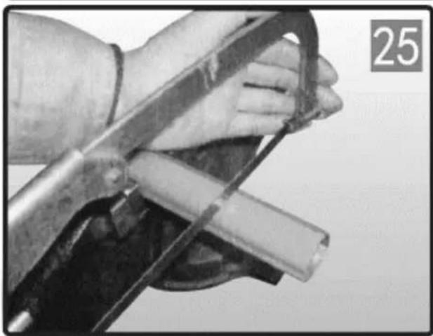
Yes, it is possible to shorten the drive tubes and plastic covers. Measure the required length considering an overlap of at least 1/3. Cut the tubes with a saw, deburr the edges, and cut the covers to the same length. Grease the inner tube before reassembling. Caution: do not modify the joints.
What to do if the shaft does not rotate freely or makes noise?
Check that the covers rotate freely and are not jammed. Ensure that the angles between tractor and implement are minimal and equal. If the noise comes from the torque limiter, disengage the PTO immediately. Insufficient lubrication or misalignment may be the cause.
How can I know if the shaft length is correct?
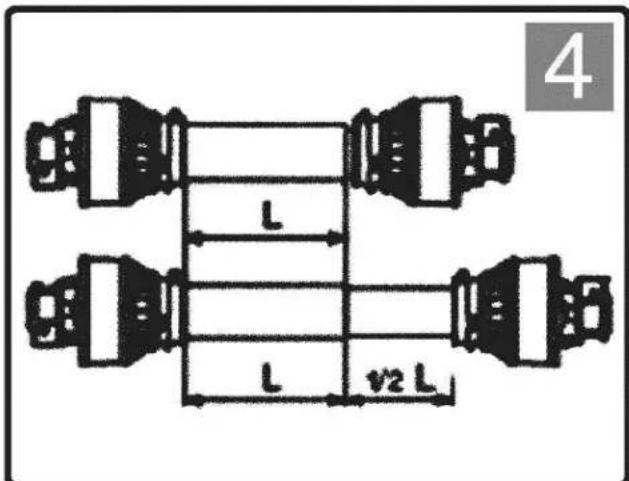
The shaft must be able to retract and extend without constraint between the machine's minimum and maximum positions. The tubes must overlap by at least 1/3 of their length in working position. The covers must never separate. Check lengths before each use.
What does the clicking noise of the torque limiter mean?
The clicking noise indicates that the friction torque limiter has exceeded its setting and is slipping. Disengage the PTO immediately to avoid damaging the implement or tractor. Check the torque setting and lubricate the device. If the problem persists, contact a professional.
How to replace a shear bolt?
Stop the tractor and turn off the engine. Replace the sheared bolt with a bolt of the same diameter, length, and grade. Use appropriate tools. Lubricate the device with a grease fitting at least once per season.
What safety precautions should I take?
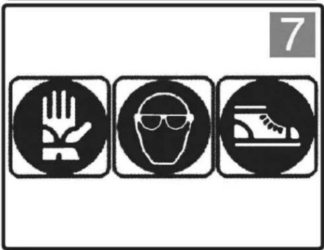
Do not wear loose clothing, remove jewelry, and tie back long hair. Use protective equipment: safety glasses, gloves, safety shoes. Ensure all guards are in place and rotate freely. Keep operators and bystanders at a distance. Always stop the engine and remove the key before any intervention.
Can I use the shaft with large angles?
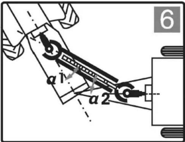
No, the angles between the joints must be minimal and equal. Too large or unequal angles can damage the shaft and cause accidents. Disengage the PTO if the angles exceed the manufacturer's recommended limits.
What to do if the locking pin does not engage?
Check that the pin is not damaged or obstructed. Clean and grease the PTO groove. Push the pin firmly while sliding the yoke. Ensure the pin returns to its initial position. If the problem persists, inspect the splines for wear.

User questions about WIE-PTO-141 Wiesenfield

0 question about this device. Answer the ones you know or ask your own.

Ask a new question about this device

The email remains private: it is only used to notify you if someone responds to your question.

No questions yet. Be the first to ask one.

Download the instructions for your Agricultural mechanical part in PDF format for free! Find your manual WIE-PTO-141 - Wiesenfield and take your electronic device back in hand. On this page are published all the documents necessary for the use of your device. WIE-PTO-141 by Wiesenfield.

USER MANUAL WIE-PTO-141 Wiesenfield
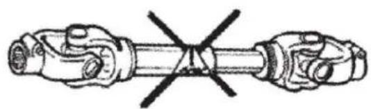
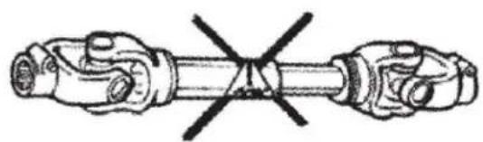
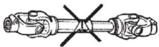
Diagram of two mechanical components with a crossed-out section, no text or symbols present

Illustration of a paintbrush applying paint to stacked books (no text or symbols)

PUSH PIN

KUGELKOLLAR

CLAMP-SCHRAUBE

CLAMP-SCHRAUBE

SCHMIERUNG:

DISMANTLE
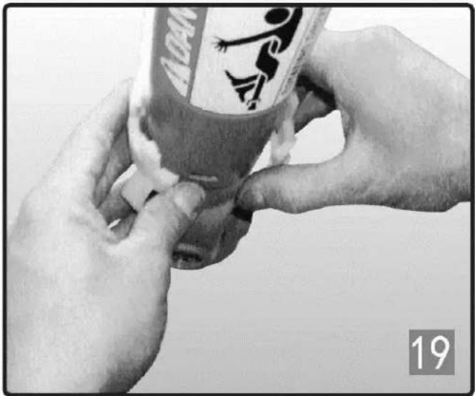
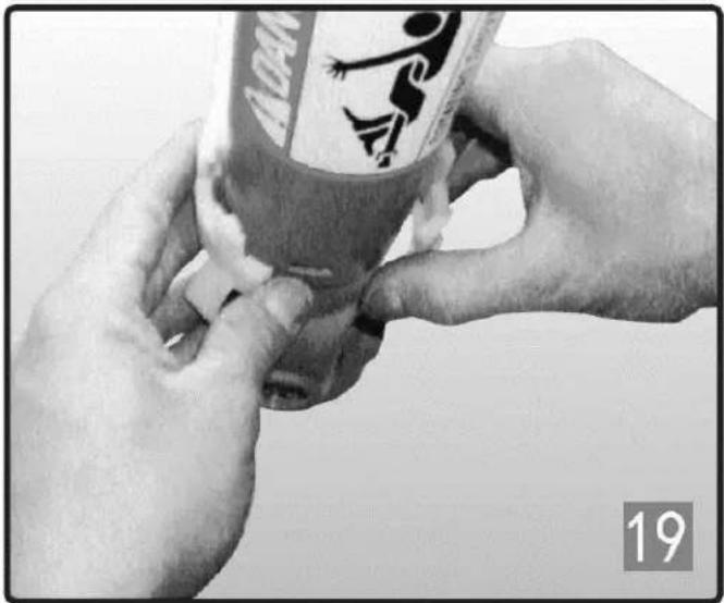
Close-up of hands holding a small container with a logo, no visible text or symbols on the container itself

Close-up of hands holding a small container with a logo, no visible text or symbols

MONTAGE

DE

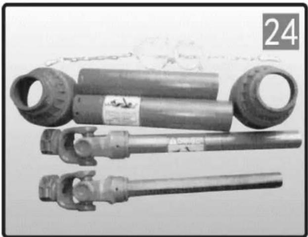
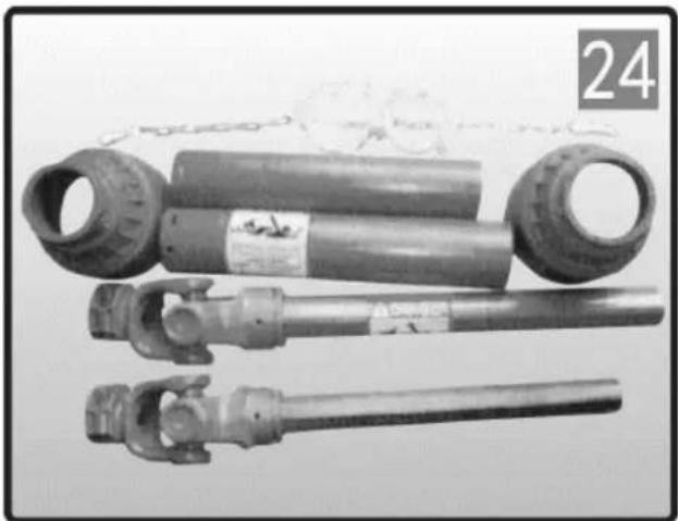
Three mechanical components with no visible text or symbols, including a numbered label '24' in the top-left corner.

ÜBERHOLFREILAUF

DREHMOMENTBEGRENZER TYP SA-RATSCHE

SB-SCHUBSCHRAUBEN- DREHMOMENTBEGRENZER

FF-
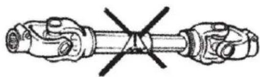
Diagram of a mechanical linkage or shaft assembly with two arms crossed, no text or symbols present

Do not operate the machine without the driveshaft, tractor, and implement shields in place. Driveshaft shields must turn freely on the driveshaft.

Keep operators and bystanders away from all moving parts.

CONTACT WITH A ROTATING DRIVESHAFT CAN CAUSE SERIOUS INJURY OR DEATH
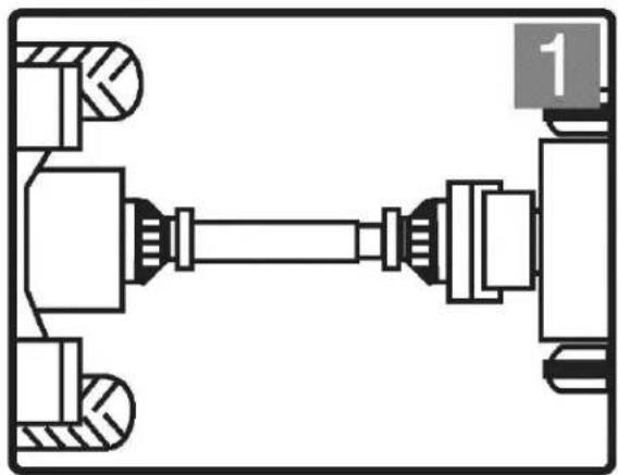
Mechanical assembly diagram showing a shaft connected to two parts, with no visible text or symbols

All rotating parts must be shielded

EN
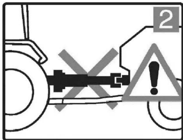
2

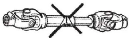
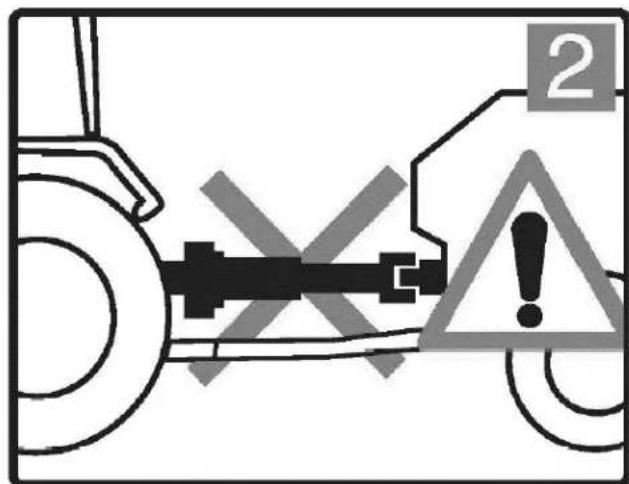
The driveline must be securely attached at both ends.

Guards must turn freely on the driveline
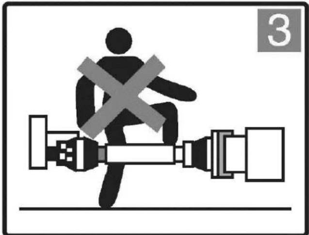
Diagram of a person sitting on a road with a cross symbol, next to a mechanical device (no text or labels)

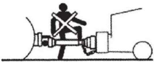
Shut off tractor engine and remove the key before approaching the implement or doing any maintenance
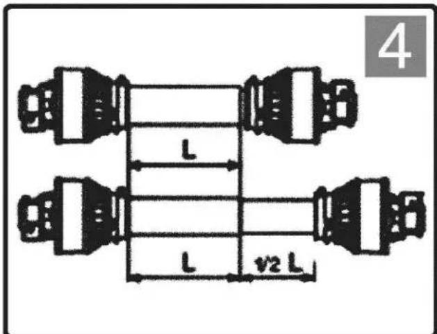
4 L L v2 L

Confirm the minimum and maximum working lengths of the drives haft.

The telescoping tubes must overlap by at least 1/3 of their length while in use.

EN
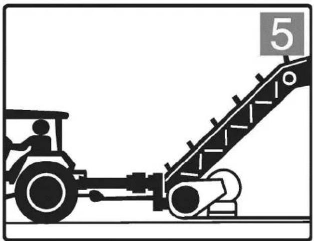
Illustration of a tractor pulling a conveyor belt with a numbered marker (5) above it, no text or symbols present.

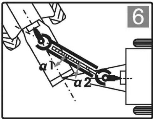
The tractor must be hitched to the implement and positioned so that the angles of the joints are minimal and equal.
a i a 2 6

Disengage the PTO if the angles are too large or not identical
7

BEFORE ATTEMPTING ANY REPAIR PROCEDURES, ALWAYS USE APPROPRIATE SUCH AS SAFETY GLASSES, SAFETY SHOES, AND GLOVES. DO NOT WEAR LOOSE OR BAGGY CLOTHING AROUND THE PTO SHAFT.

EN
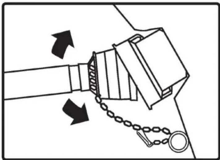
Diagram of a mechanical device with chains and arrows indicating motion (no text or symbols)

Ensure that the driveline is securely attached to the tractor and the implement before operating.
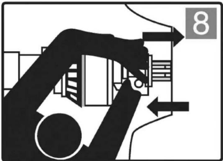
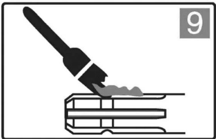
Silhouette of a robotic arm interacting with a mechanical device, no text or symbols visible

Illustration of a paintbrush applying paint to stacked books (no text or symbols)

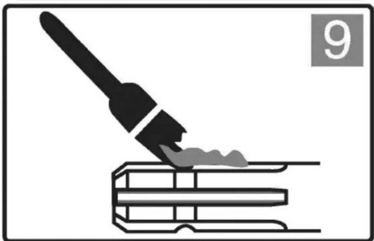
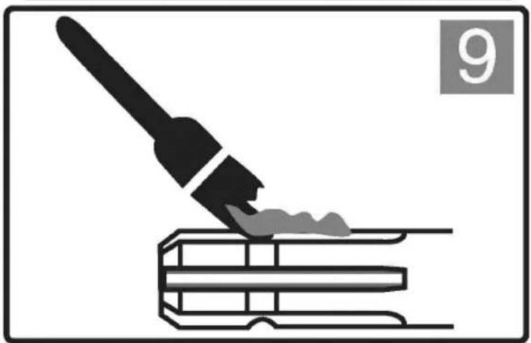
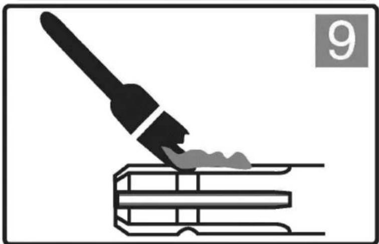
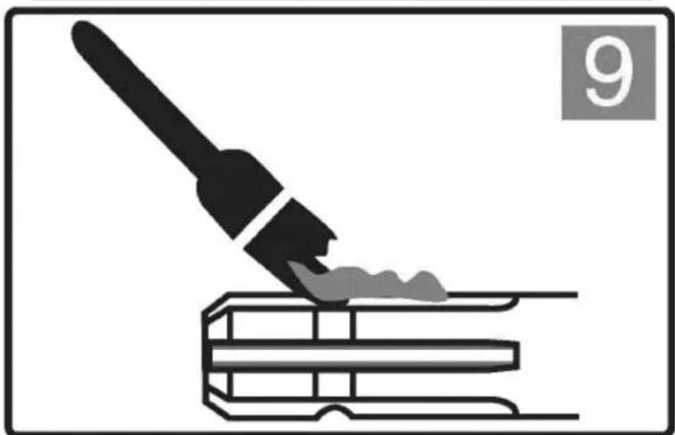
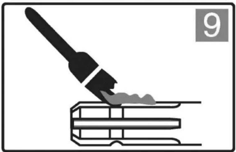
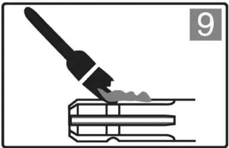
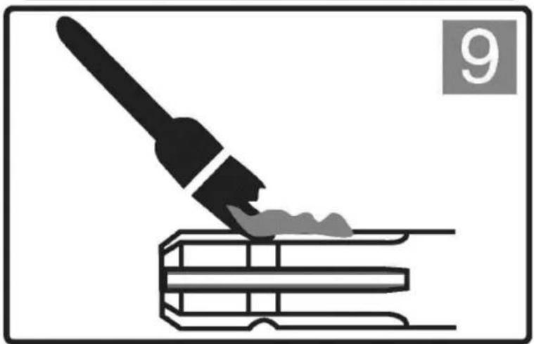
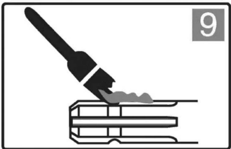
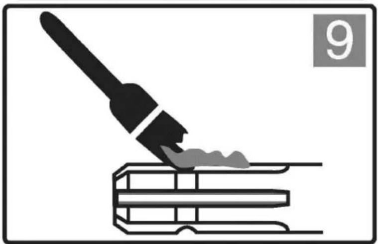
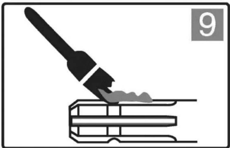
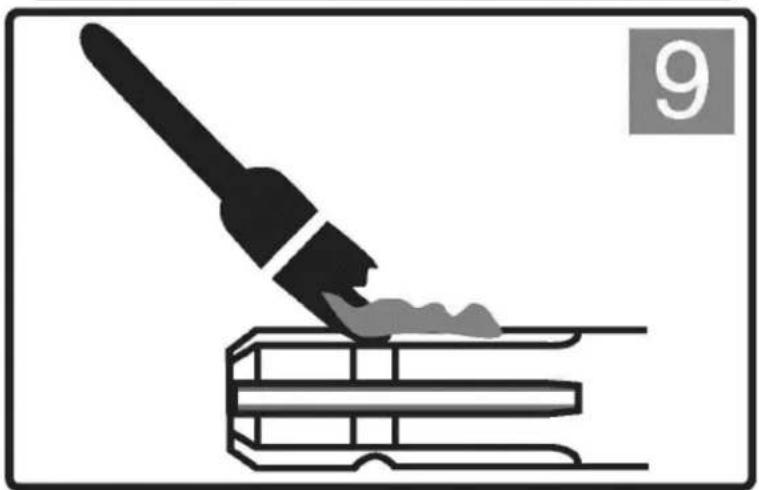
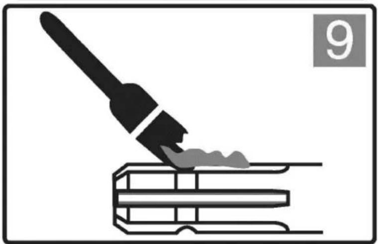
Clean and grease the tractor PTO and implement shaft before installing the driveline.

EN
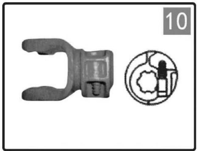
Two mechanical components: a clamp-like tool and a circular diagram with internal components (no text or symbols)

PUSH PIN

Push the pin and slide the yoke onto the PTO shaft so that the pin engages the groove on the PTO.

Make sure that the pin returns to its initial position after attachment to the shaft.
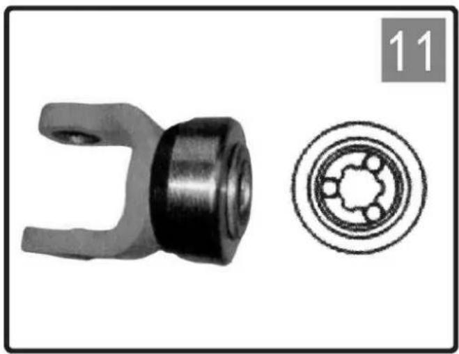
Mechanical component with two views: a circular cross-section showing internal gear teeth and a mechanical bracket (no text or symbols)

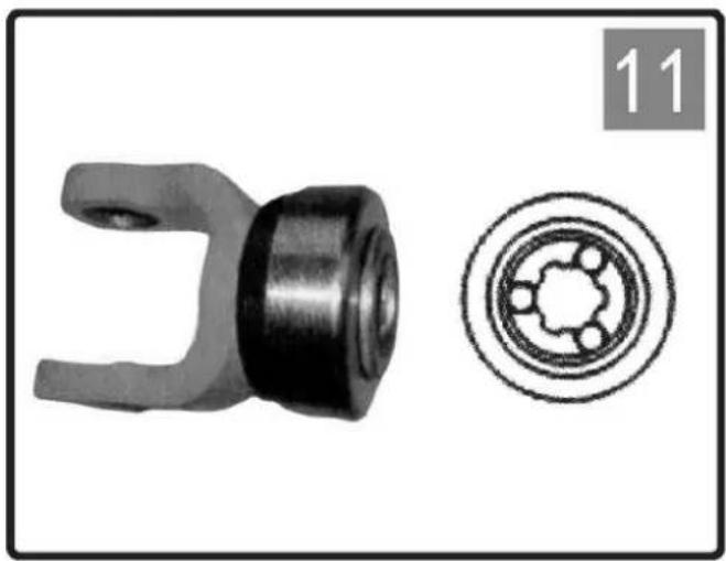
BALL COLLAR

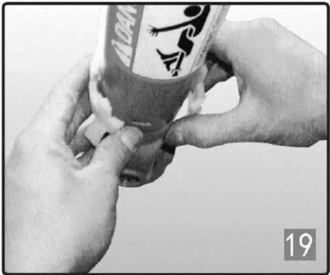
Slide the collar to the open position. Slide the yoke onto the splined shaft. Release the collar and adjust until the yoke is properly attached to the shaft.

EN
Two mechanical components: a cylindrical clamp and a shield-shaped bracket, both without any visible text or symbols.

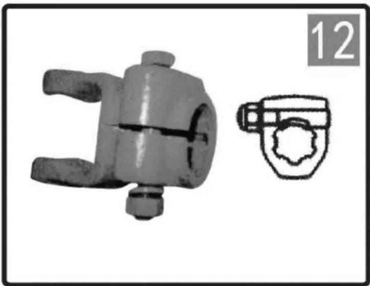
CLAMP BOLT

Slide the yoke onto the PTO and insert the bolt.
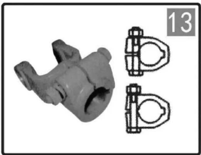
3D mechanical component with two side-view diagrams (no text or symbols)

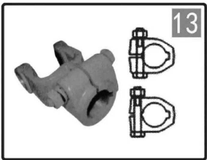
CLAMP BOLT

Slide the yoke onto the PTO and insert the bolt.

EN
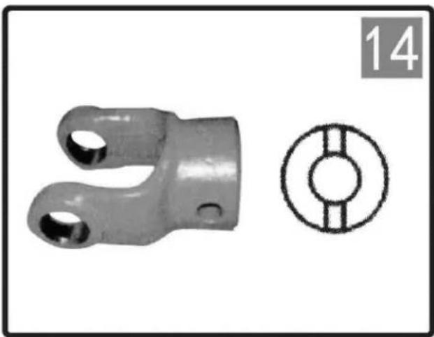
Two mechanical components: a metal bracket with two holes and a circular hole with two parallel rods (no text or symbols)

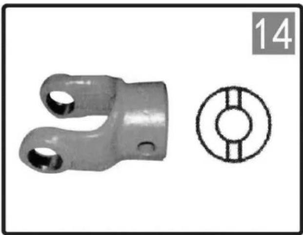
PLAIN BORE AND KEYWAY

Choose the bolt length in such a way as to minimize protrusion.
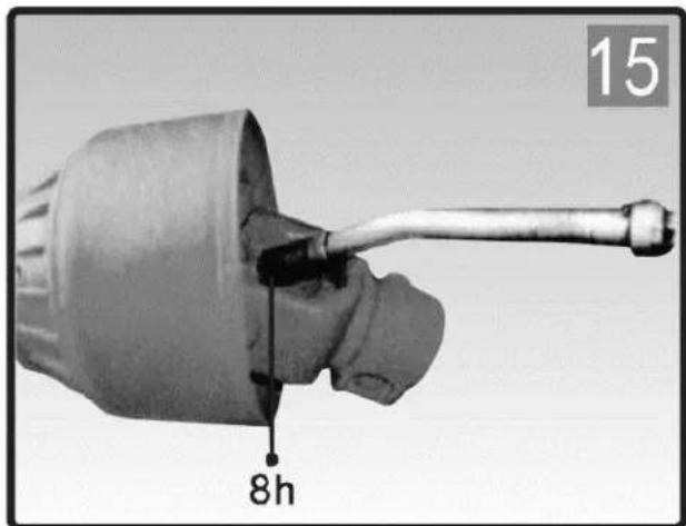
15 8h

16 8h 40h

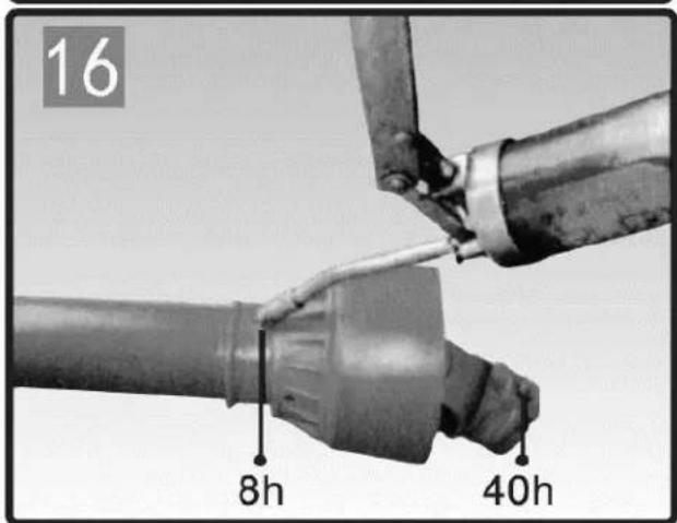
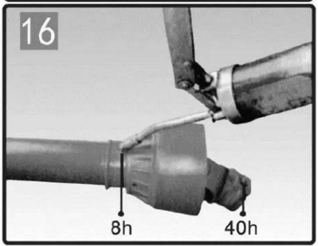
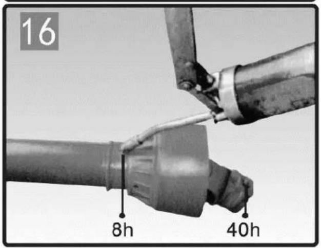
LUBRICATION:

Frequent lubrication is required, Grease the driveline shaft parts

After the number of hours used As shown on the drawing

EN
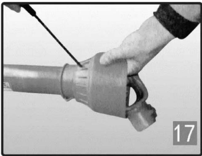
Close-up of a hand holding a cylindrical mechanical component with a tool, no visible text or symbols

DISMANTLE

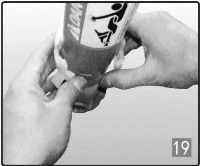
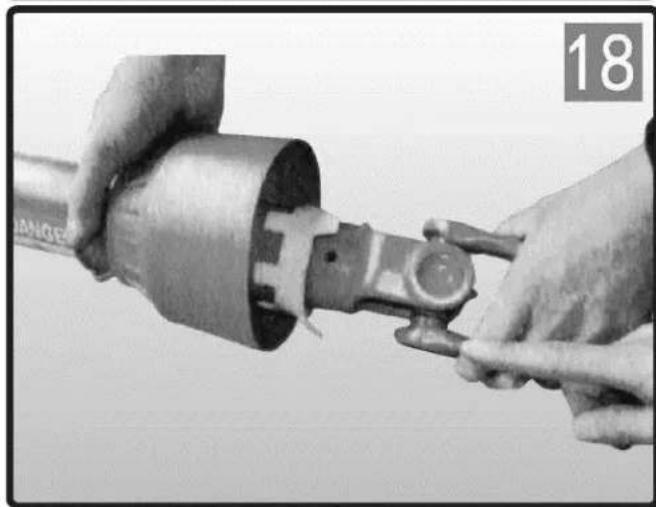
  1. Dismantle the inside tube from the outside one.
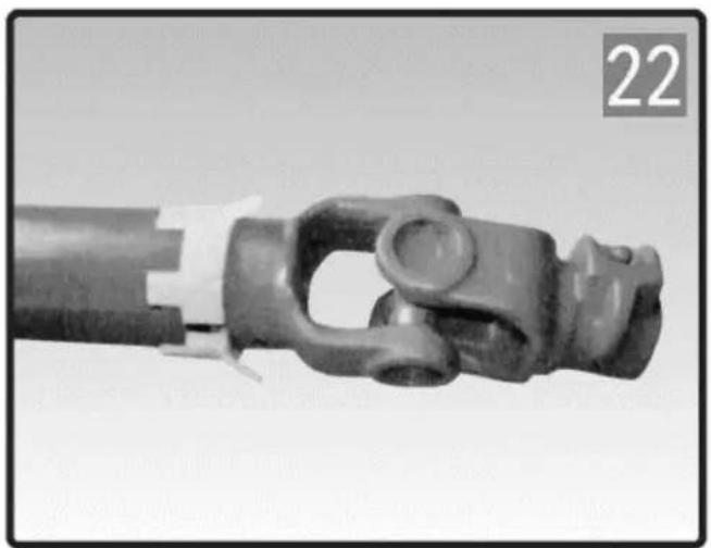
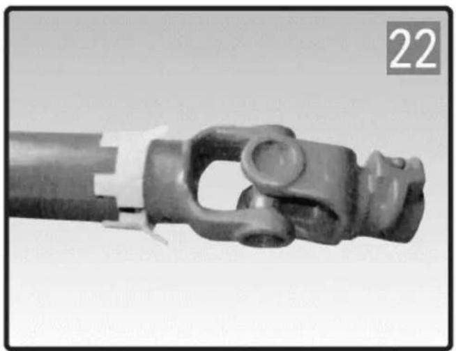
  2. Take a screwdriver to depress the buckle from one to another then to take outside tube apart from plastic cap.
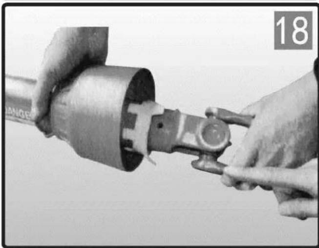
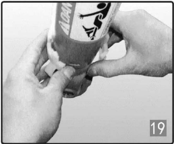
Close-up of hands connecting a mechanical component to a cylindrical part, no visible text or symbols

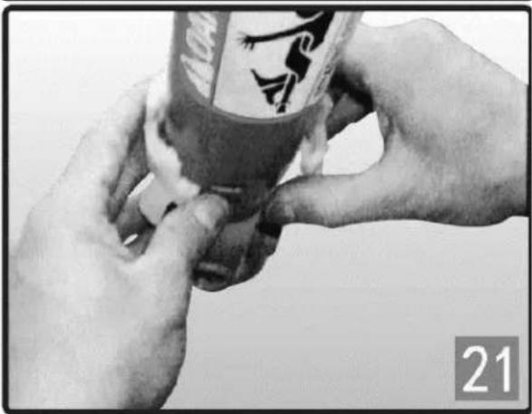
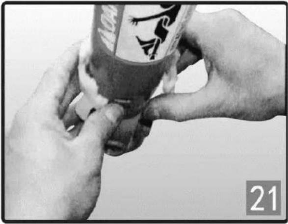
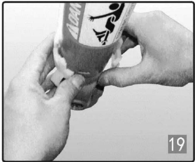
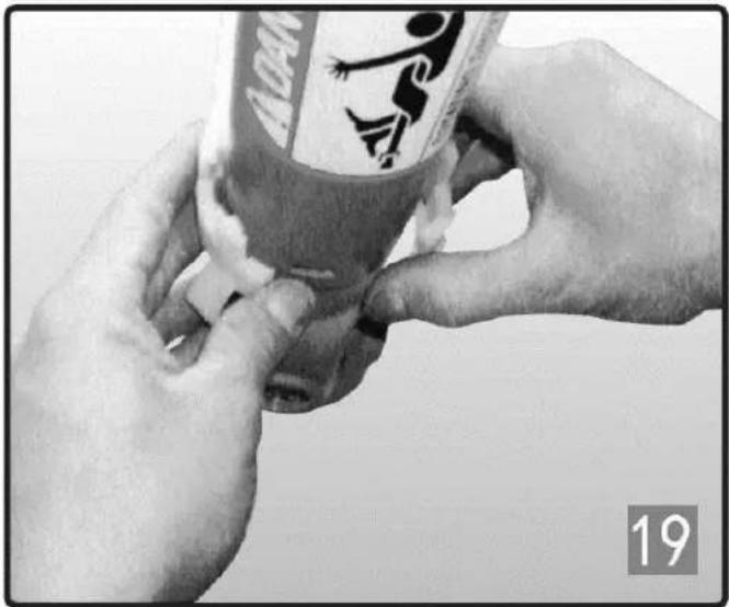
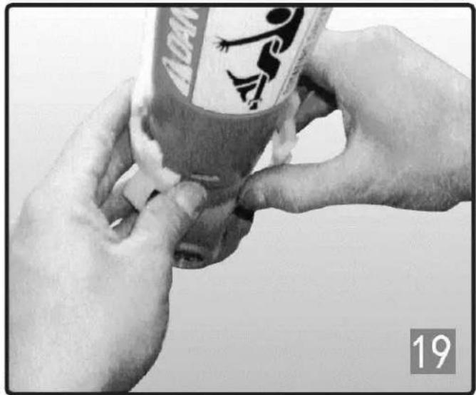
Close-up of hands holding a small container with a logo, no visible text or symbols on the container itself

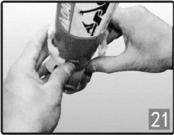
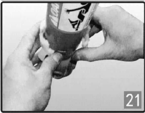
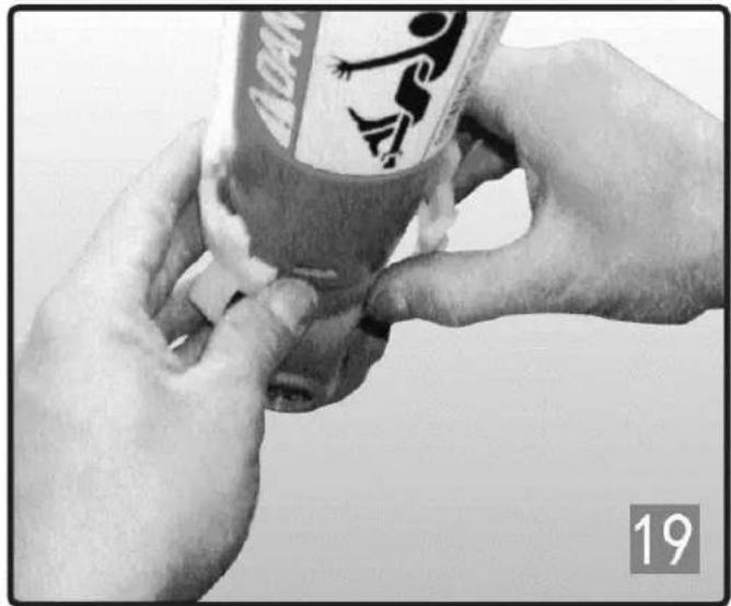
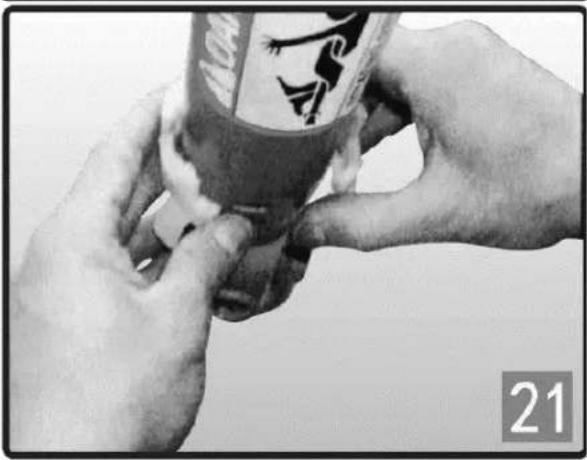
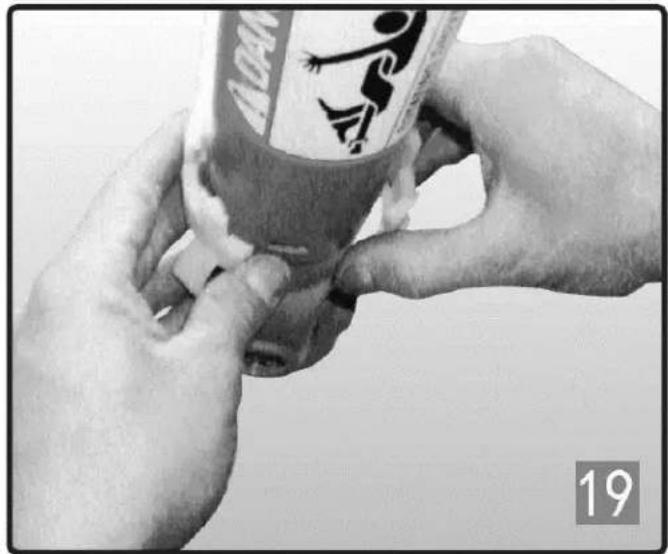
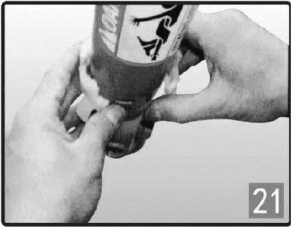
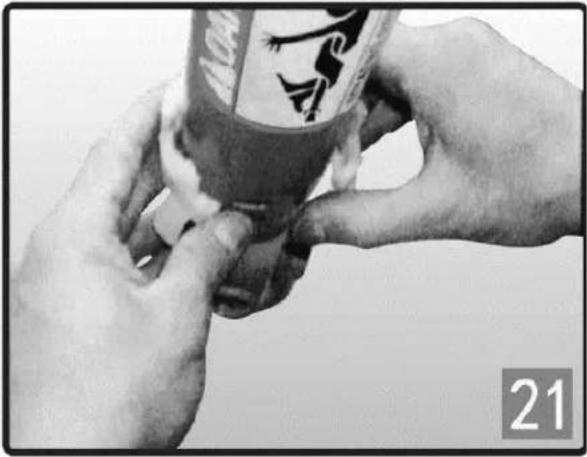
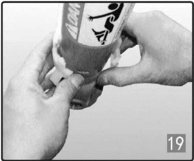
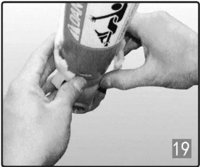
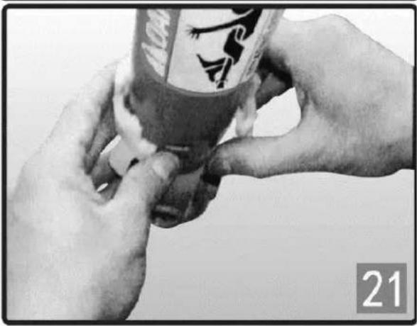
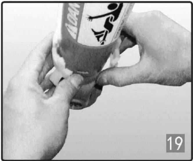
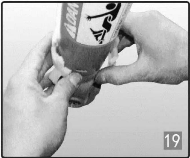
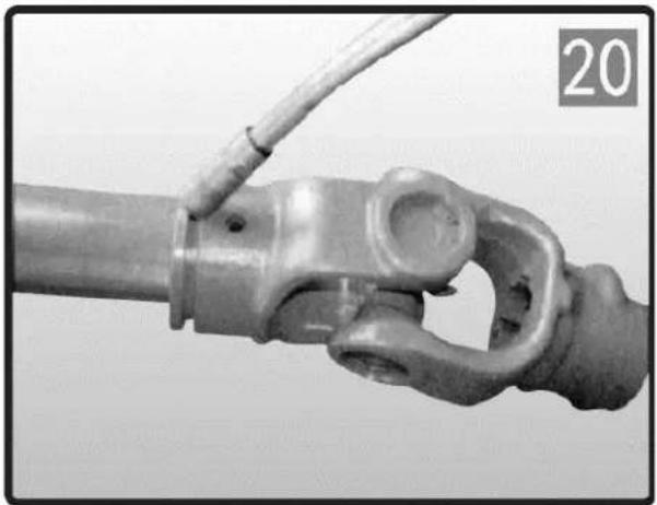
  1. Remove the nylon bearing from the slot of the yoke.
  2. Repeat the above-mentioned steps for the other side.

EN
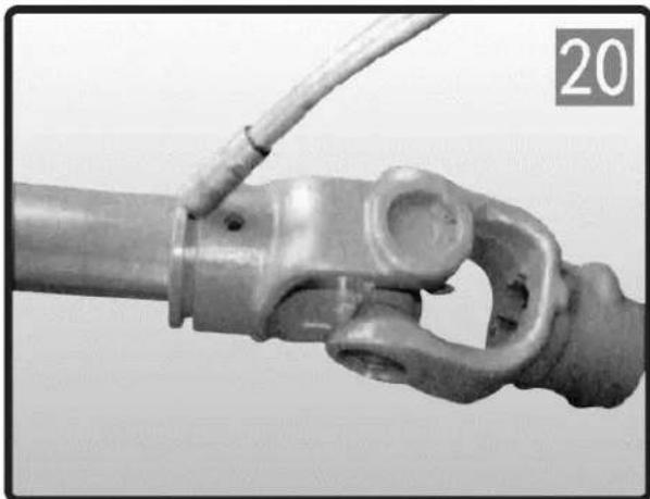
Close-up of a mechanical joint or connector being held by a wire, with no visible text or symbols.

INSTALLATION

Close-up of hands assembling a cylindrical container with a logo (no visible text or symbols)

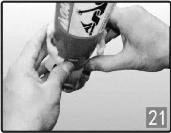
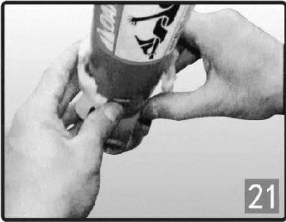
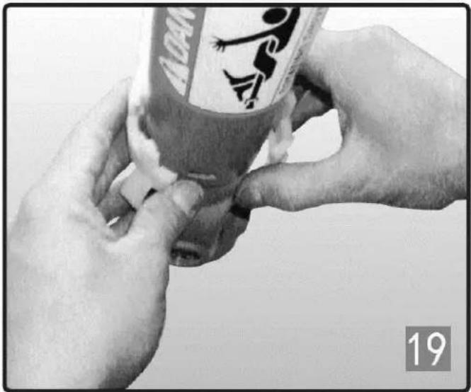
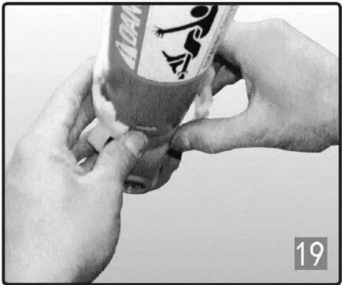
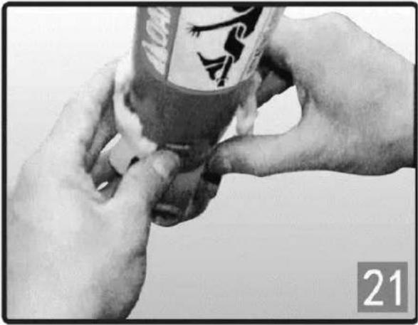
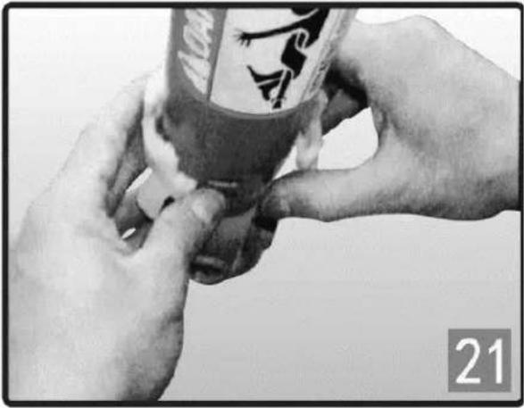
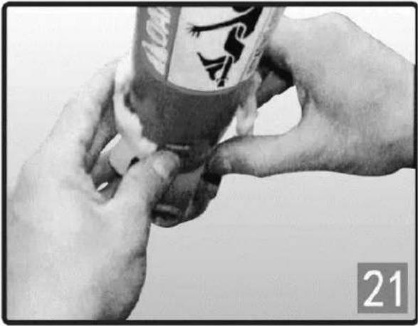
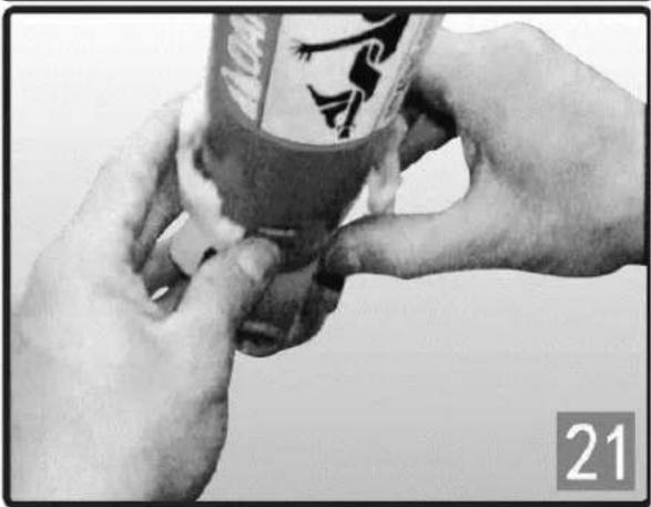
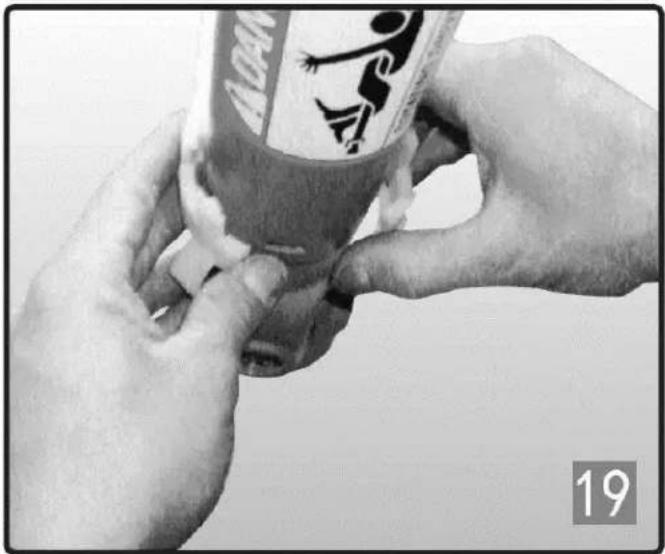
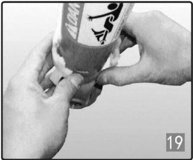
  1. Grease the slot on the yoke.
  2. Put the nylon bearing into the slot of the yoke.

EN
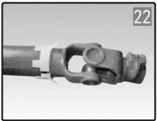
Close-up of a mechanical connector or clamp component with no visible text or symbols

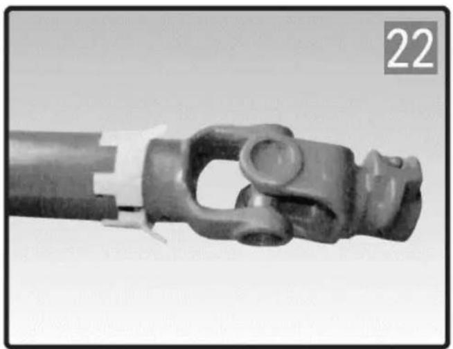
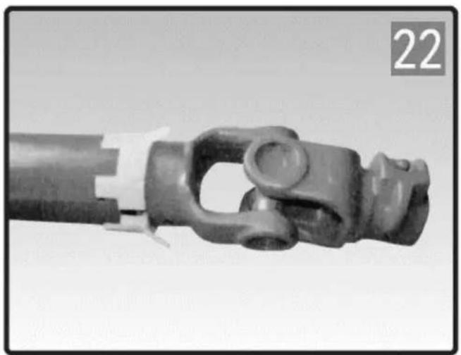
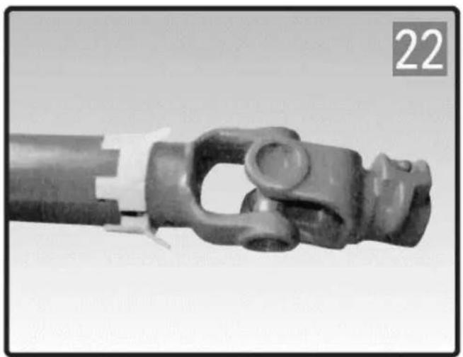
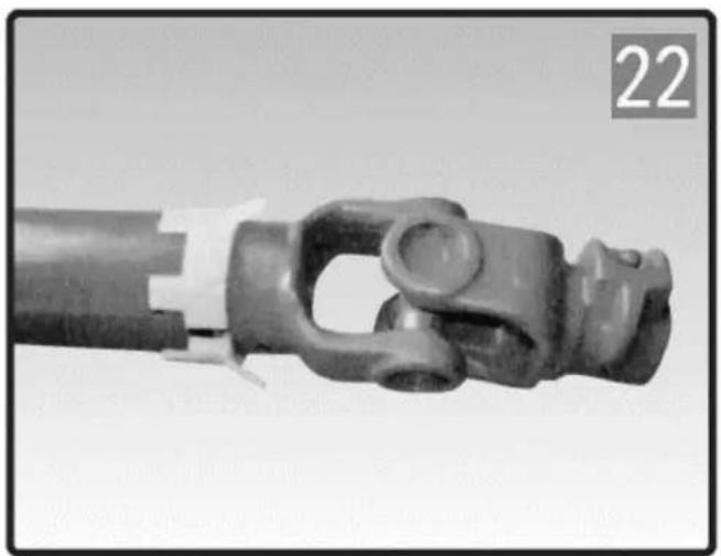
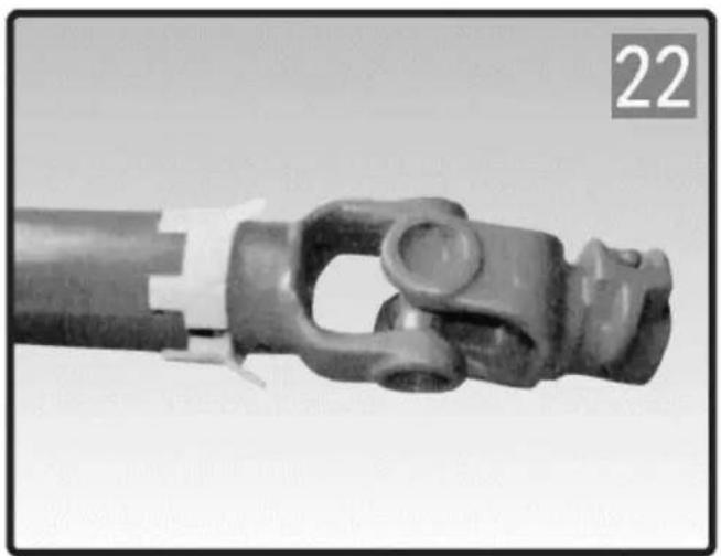
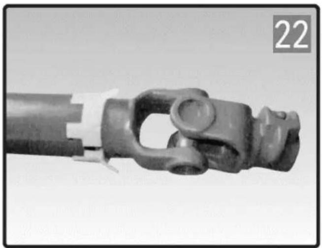
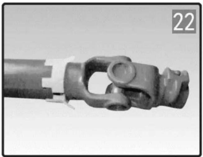
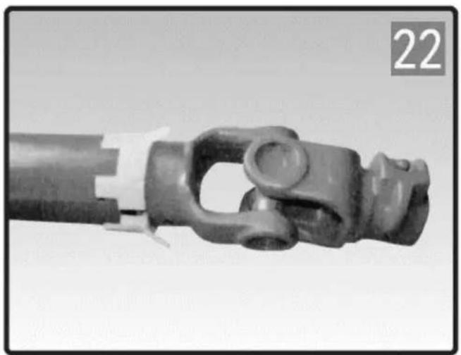
  1. Put the inside tube with the yoke into its plastic cover.
  2. Align the bearing with the two holes on the

plastic cap and then press it.
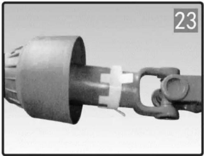
Close-up of a mechanical device with a handle and connector (no visible text or symbols)

EN

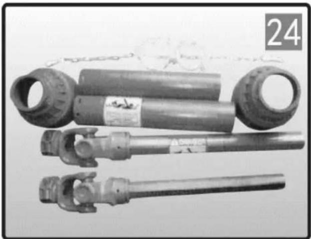
Three mechanical components with no visible text or symbols, including a numbered label '24' in the top-left corner.

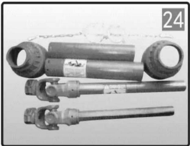
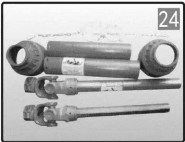
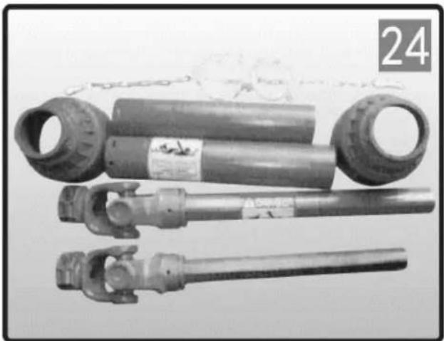
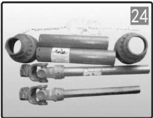
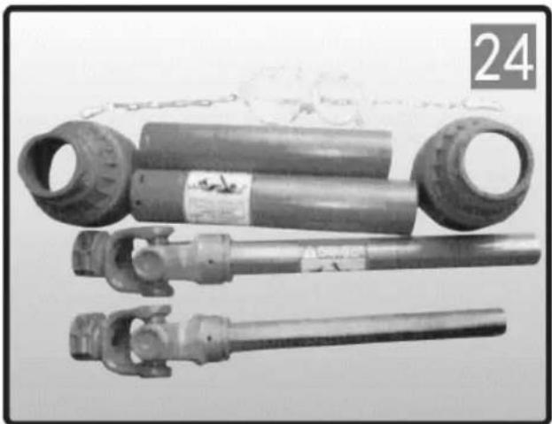
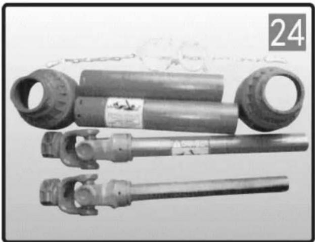
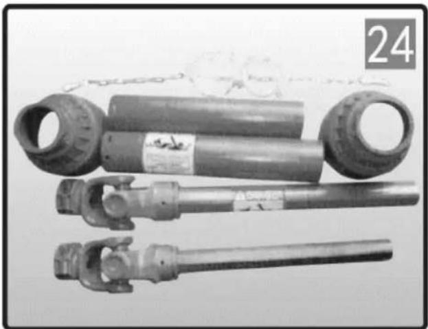
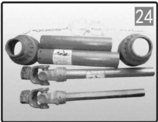
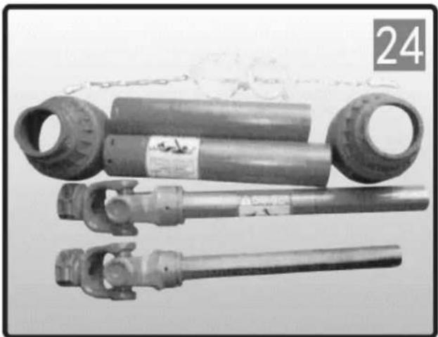
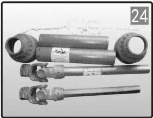
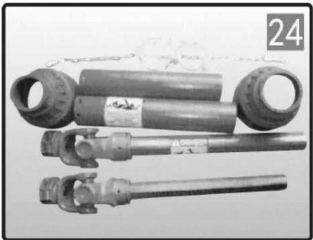
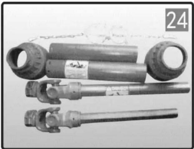
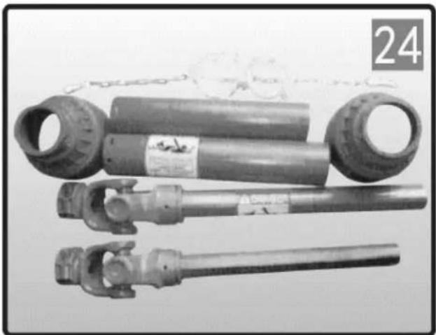
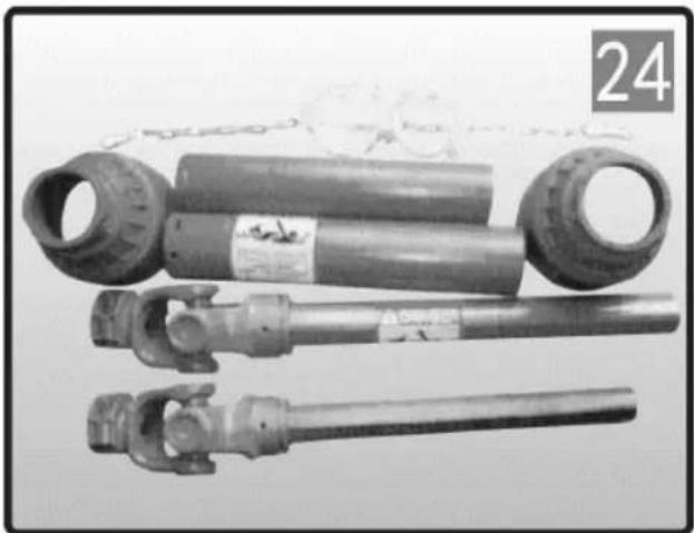
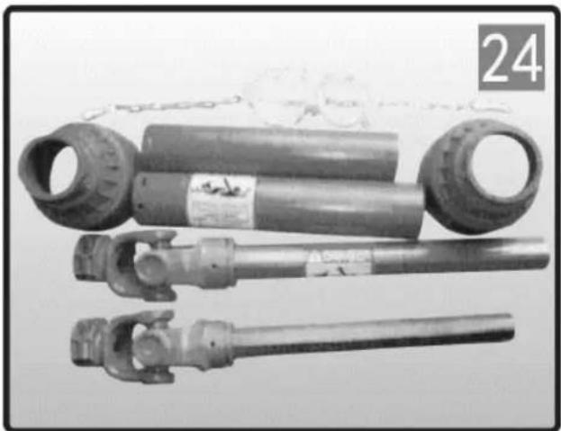
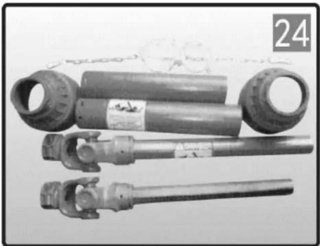
SHORTENING THE DRIVESHAFT (We don't recommend modification to our products.)
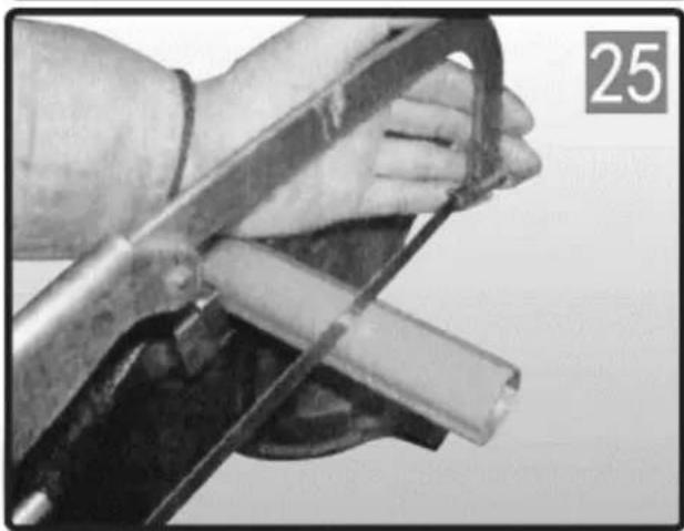
Close-up of hands using a tool to handle a mechanical component, no visible text or symbols

  1. Remove shielding.

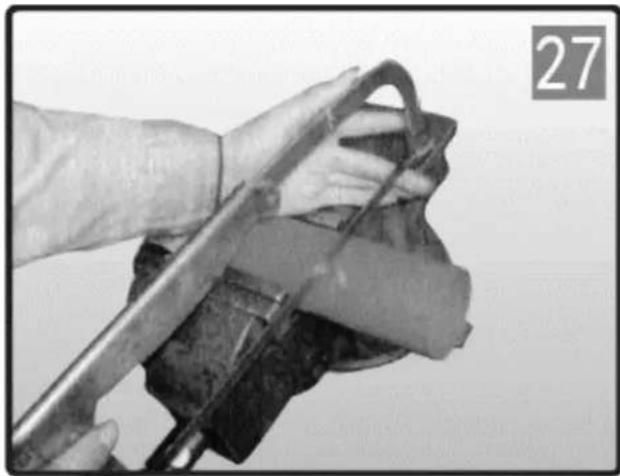
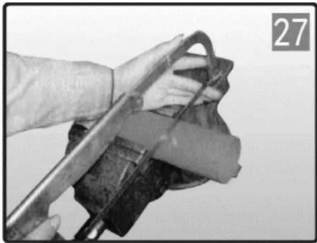
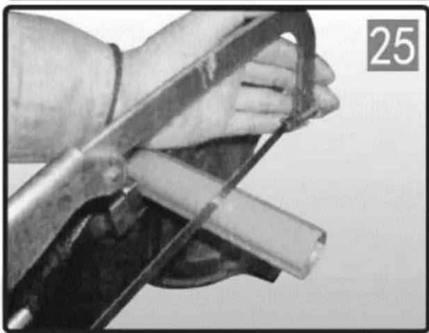
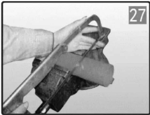
  2. Shorten the inside and outside drive tubes to the required length. Shorten the drive tubes one at a time by cutting the same length from both inside and outside tubes.
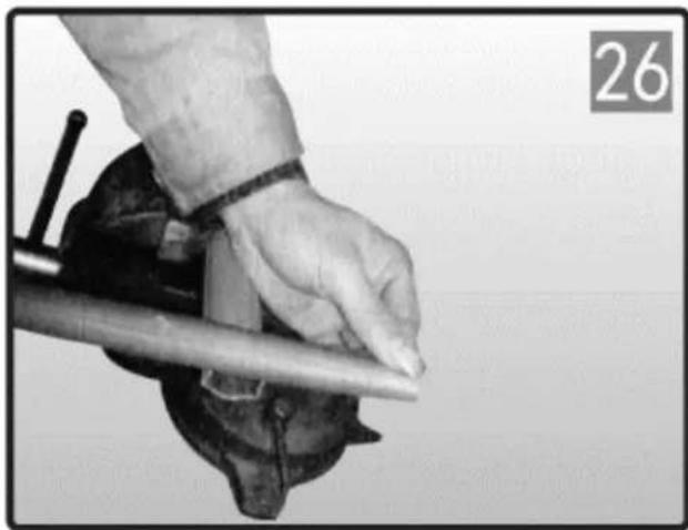
Close-up of a hand using a tool to cut or press a piece of material, no visible text or symbols

  1. Deburr edges of the drive tube with a file and clean all filings from the tubes.

EN
Close-up of a hand using a tool to clean or wash a material, no visible text or symbols

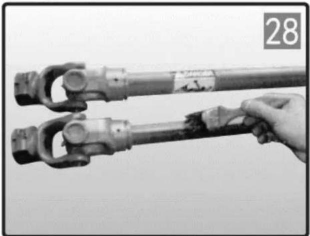
  1. Shorten the plastic shield tubes one at a time by cutting the same length that was cut from the inside drive tubes.
Close-up of two mechanical components being handled with a hand, no visible text or symbols

  1. Grease the internal drive tube and reassemble the shielding on the driveshaft.
Close-up of a mechanical tool or device with a diagonal line extending from it, no visible text or symbols.

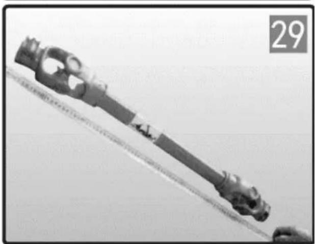
Check the length of the driveshaft in the minimum and maximum positions of the machine. The drive tubes should overlap by 1/3 of their length during working conditions; Shield tubes should never separate while in use.

EN
Metal mechanical component with two circular ends and a central hub, shown against a plain background (no text or symbols visible)

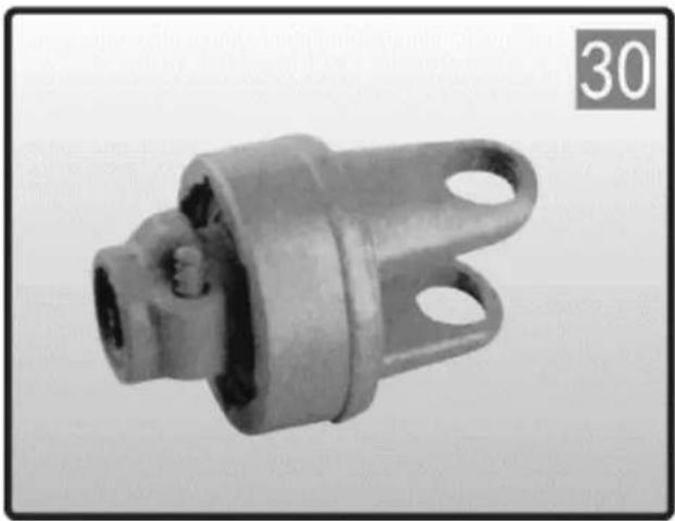
RA-OVERRUNNING CLUTCH

This device prevents transmission of inertial loads from implement to the tractor during deceleration or stopping of the PTO. Keep clear of the implement until all parts have stopped moving. Lubricate every 50 hours of use and after storage.
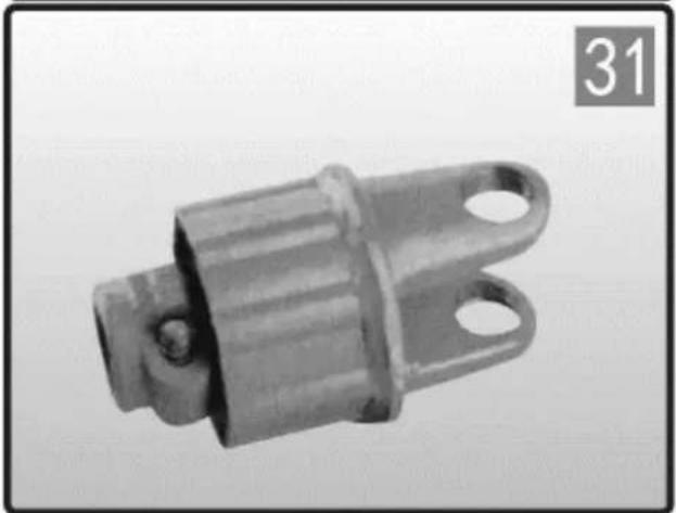
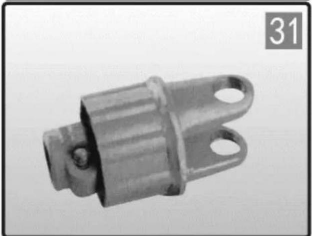
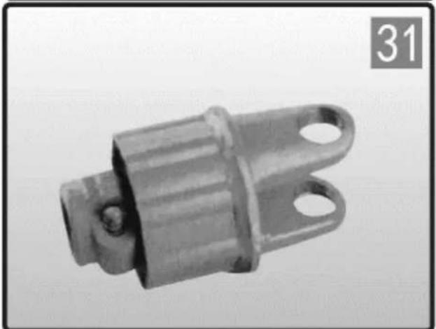
Metal mechanical component with flanged ends and a central hub, labeled with number 31 in the corner (no other text or symbols)

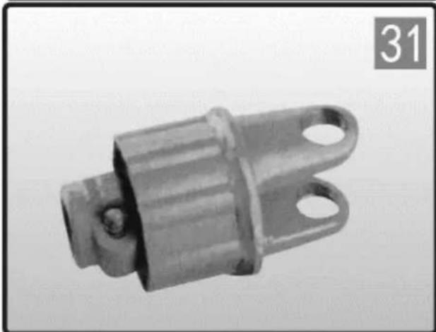
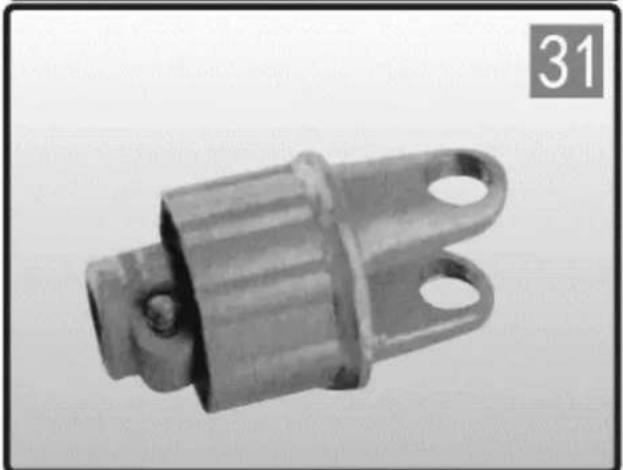
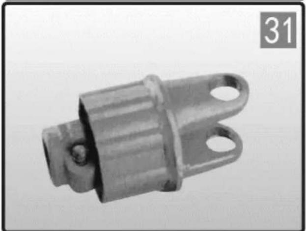
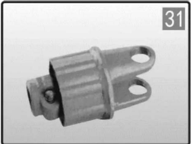
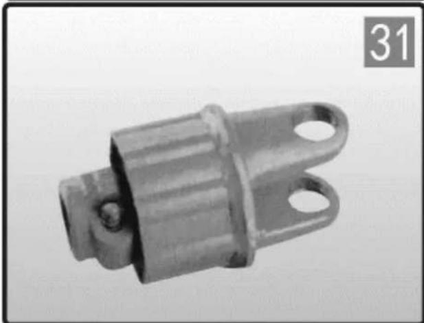
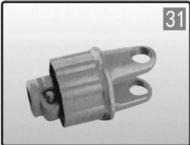
SA-RATCHET TYPE TORQUE LIMITER

This device interrupts the transmission of power when the torque exceeds the setting. Immediately disengage the PTO when ratcheting sounds are heard. Lubricate every 50 hours of use and after storage.
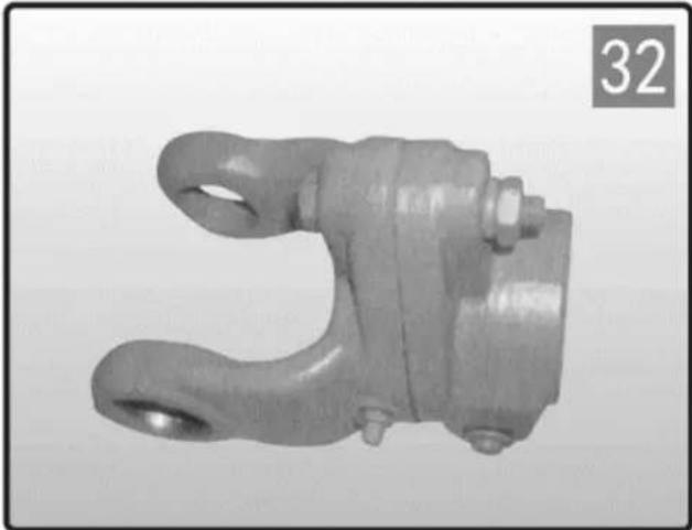
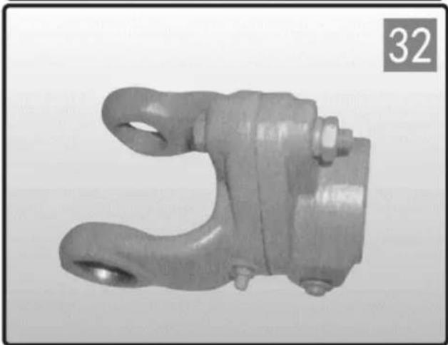
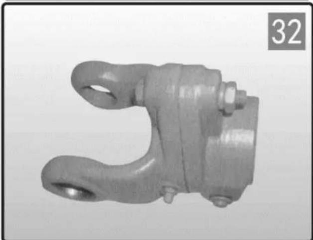
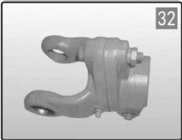
Metallic mechanical component with a U-shaped end and mounting holes (no text or symbols visible)

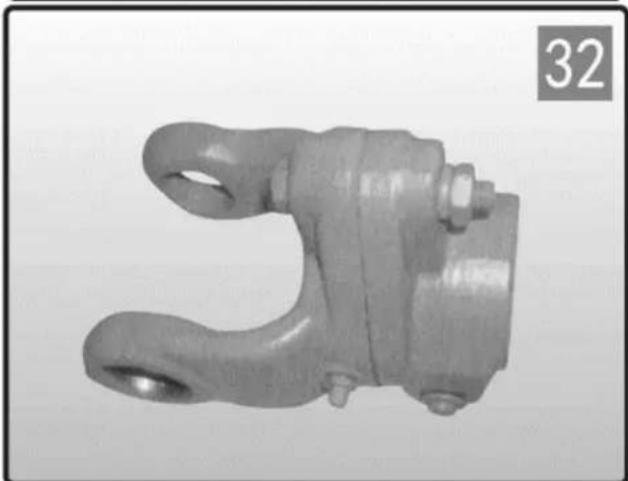
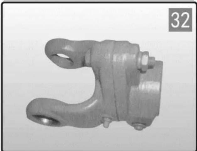
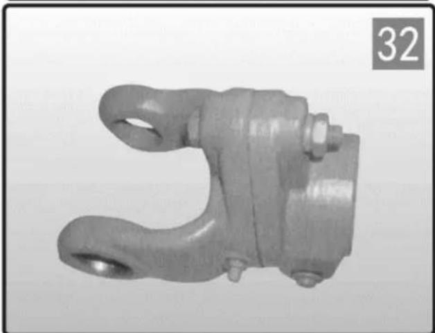
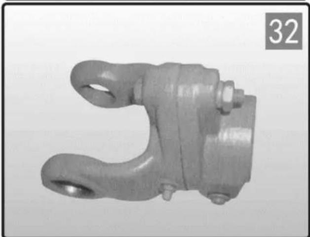
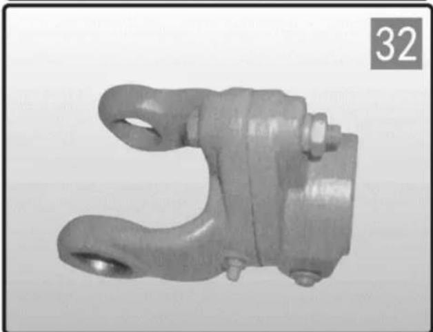
SB-SHEAR BOLT TORQUE LIMITER

This device interrupts the transmission of power by shearing a bolt when the torque exceeds the setting. Replace the sheared bolt with the same diameter, length and grade as the original. Lubricate the SB with grease fitting at least once every season and after a period of disuse.

EN
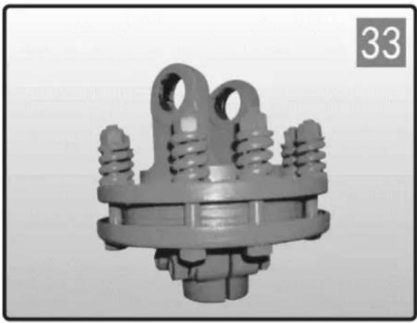
3D rendered mechanical component with springs and a central hub, no visible text or symbols

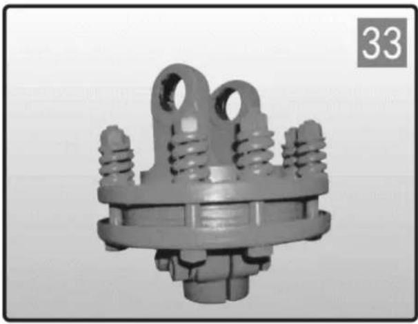
FF-FRICTION TORQUE LIMITER

Limits torque transmission to the setting value. Do not change spring compression as this will modify the device setting.

The torque setting is adjusted by increasing or decreasing the height of the springs. To increase/decrease the torque

setting tighten/loosen the eight nuts by 1/4 of a turn and check for correct operation. Repeat the procedure if necessary. Avoid excessive tightening of the bolts implement, tractor, or driveline damage may occur.

PL
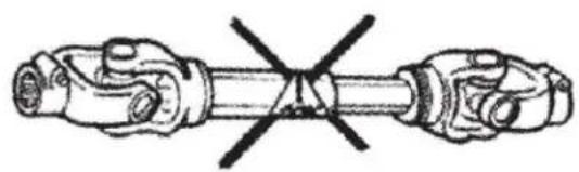
Diagram of two mechanical components with a crossed-out black line indicating a joint or connection (no text or symbols present)

Illustration of a paintbrush applying paint to stacked books (no text or symbols)

WCIŚNIJ PIN

KOŁNIERZ PIŁKOWY

ŚRUBA ZACISKOWA

ŚRUBA ZACISKOWA

OTWOR GŁADKI I ROWEK KLUCZOWY

SMAROWANIE:

ZDEMONTOWAĆ
Close-up of hands holding a small container with a logo, no visible text or symbols on the object itself

Close-up of hands holding a small container with a logo, no visible text or symbols

MONTAŻ

PL

Three industrial mechanical components with no visible text or symbols

RA-SPRZĘGŁO BIEŻĄCE

OGRANICZNIK MOMENTU

OBROTOWEGO TYPU SA-RATCHET

SB-OGRANICZNIK MOMENTU OBROTOWEGO ŚRUBY

ŚCINAJĄCEJ

FF-OGRANICZNIK MOMENTU OBROTOWEGO
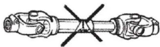
Diagram of two mechanical components with a crossed-out section, no text or symbols present

Illustration of a paintbrush applying powder to stacked books (no text or symbols)

PUSH PIN

KULIČKOVÝ LÍMEC

SVORNÝ ŠROUB

SVORNÝ ŠROUB

OBYČEJNÝ VRTÁNÍ A KLÍČOVÁ DRÁHA

MAZÁNÍ:

DEMONTOVAT
Close-up of hands holding a small container with a logo, no visible text or symbols on the object itself

MONTÁŽ

Close-up of hands assembling a cylindrical container with a logo (no visible text or symbols)

CZ

Three industrial mechanical components with no visible text or symbols

Metal mechanical component with flanged ends and a central hub (no visible text or symbols)

Metallic mechanical component with a U-shaped end and bolted joint (no text or symbols visible)

FF-FRICTION OMEZOVAČ MOMENTU

Diagram of two mechanical components with a crossed-out black line indicating a joint or connection (no text or symbols present)

Illustration of a paintbrush applying powder to stacked books (no text or symbols)

PUSH PIN

COLLIER À BALLES

BOULON DE SERRAGE

BOULON DE SERRAGE

ALÉSAGE LISSE ET RAINURE DE CLAVETTE

LUBRIFICATION:

DÉMANTELER
Close-up of hands holding a small container with a logo, no visible text or symbols on the container itself

Close-up of hands holding a small container with a logo, no visible text or symbols

ASSEMBLAGE

FR

Three industrial mechanical components with no visible text or symbols

RACCOURCISSEMENT DE L'ARBRE DE TRANSMISSION

RA-EMBRAYAGE À ROUE LIBRE

LIMITEUR DE COUPLE TYPE SA- RATCHET

LIMITEUR DE COUPLE À BOULON DE CISAILLEMENT SB
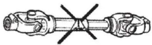
Diagram of two mechanical components with a crossed-out black line indicating a joint or connection (no text or symbols present)

Illustration of a paintbrush applying powder to stacked books (no text or symbols)

SPILLO

COLLARE A PALLA

BULLONE DI MORSETTO

BULLONE DI MORSETTO

ALESAGGIO SEMPLICE E SEDE PER CHIAVETTA
16 8h 40h

LUBRIFICAZIONE:

SMANTELLARE

Close-up of hands holding a small container with a logo, no visible text or symbols on the container itself

MONTAGGIO

IT
Close-up of a mechanical connector or clamp component with no visible text or symbols

IT

Three mechanical components with no visible text or symbols, including a numbered label '24' in the top-left corner.

FRIZIONE A RULLO RA

LIMITATORE DI COPPIA TIPO SA- RATCHET

LIMITATORE DI COPPIA FF-FRICTION
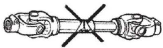
Diagram of two mechanical components with a crossed-out black line indicating a joint or connection (no text or symbols present)

Illustration of a paintbrush applying powder to stacked books (no text or symbols)

PIN DE EMPUJE

COLLAR DE BOLA

PERNO DE ABRAZADERA

PERNO DE ABRAZADERA

AGUJERO LISO Y CHAVETERA
16 8h 40h

LUBRICACIÓN:

DESMANTELAR

Close-up of hands holding a small container with a logo, no visible text or symbols on the container itself

Close-up of hands holding a small container with a logo, no visible text or symbols

MONTAJE

ES

Three mechanical components with no visible text or symbols, including a numbered label '24' in the top-left corner.

EMBRAGUE DE RUEDA LIBRE RA

LIMITADOR DE PAR TIPO TRINQUETE SA
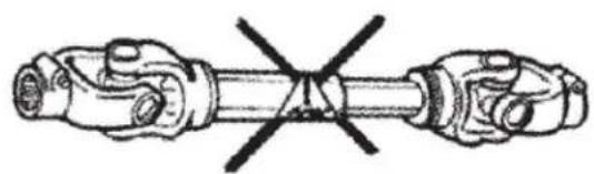
Diagram of two mechanical components with a crossed-out line indicating a joint or connection (no text or symbols present)

Illustration of a paintbrush applying paint to stacked books (no text or symbols)

PUSH PIN

BALL COLLAR

BILINCSCSAVAR

BILINCSCSAVAR

SIMA FURAT ÉS KULCSNYÍLÁS
16 8h 40h

KENÉS:

DISMANTLE

Close-up of hands holding a small container with a logo, no visible text or symbols on the container itself

Close-up of hands holding a small container with a logo, no visible text or symbols

ÖSSZESZERELÉS

HU

Three industrial mechanical components with no visible text or symbols

Metal mechanical component with flanged ends and a central hub, labeled with number 31 in the corner (no other text or symbols)

Metallic mechanical component with two curved arms and a central hub, labeled with number 32 in the corner (no text or symbols on the component itself)

RA-FELÜLFUTÓ TENGELYKAPCSOLÓ

FF-SÚRLÓDÁSI

NYOMATÉKKORLÁTOZÓ
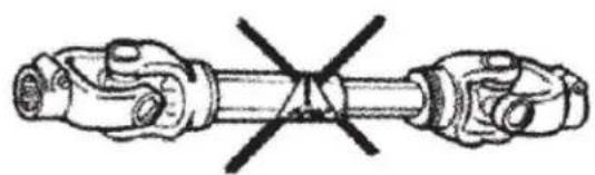
Diagram of two mechanical components with a crossed-out line indicating a joint or connection (no text or symbols present)

Illustration of a paintbrush applying powder to stacked books (no text or symbols)

PUSH PIN

KUGLEKRAVE

KLAMPEBOLT

KLAMPEBOLT

GLAT BORING OG KILESPOR

SM∅RING:

DISMANTLE
Close-up of hands holding a small container with a logo, no visible text or symbols on the container itself

MONTERING

FI
Close-up of a mechanical connector or clamp component with no visible text or symbols

FI
Three industrial mechanical components with no visible text or symbols

RA-OVERL∅BSKOBLING

SA-RATCHET TYPE

MOMENTBEGRÄNSER

SB-MOMENTBEGRÄNSER TIL FORSKYDNINGSBOLTE

Denne anordning afbryder kraftoverførslen ved at klippe en bolt over, når drejningsmomentet overstiger indstillingen.

FF-

FRIKTIONSMOMENTBEGRÄNSER
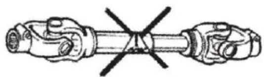
Diagram of two mechanical components with a crossed-out line indicating a joint or connection (no text or symbols present)

Illustration of a paintbrush applying paint to stacked books (no text or symbols)

PUSH PIN

PALLOKAULUS

PURKISTUSPULTTI

PURKISTUSPULTTI

PELÄINEN PORAUS JA KEYWAY

VOITELU:

PURKAA
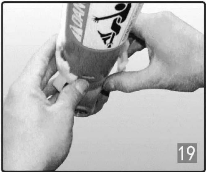
Close-up of hands holding a small container with a logo, no visible text or symbols on the container itself

ASENNUS

  1. Rasvaa ikeen ura.
  2. Aseta nailonlaakeri ikeen uraan.

Close-up of hands holding a small container with a logo, no visible text or symbols

FI
Close-up of a mechanical connector or clamp component with no visible text or symbols

Completely blank white image with no visible content, text, or symbols.

FI
Three mechanical components with no visible text or symbols, including a numbered label '24' in the top-left corner.

Metal mechanical component with flanged ends and a central hub, labeled with number 31 in the corner (no other text or symbols)

Metallic mechanical component with a U-shaped end and bolted joint (no text or symbols visible)

RA-YLIKYTKIN

VÄÄNTÖMOMENTIN RAJOITIN

VÄÄNTÖMOMENTIN RAJOITIN

FF-KITKAMOMENTIN RAJOITIN
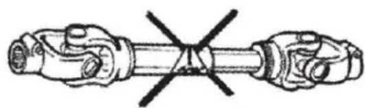
Diagram of two mechanical components with a crossed-out line indicating a joint or connection (no text or symbols present)

Illustration of a paintbrush applying paint to stacked books (no text or symbols)

PUSH PIN

BAL KRAAG

KLEM BOUT

KLEM BOUT

GLADDE BORING EN SPIEGANG

SMERING:

DEMONTEREN
Close-up of hands holding a small container with a logo, no visible text or symbols on the container itself

Close-up of hands holding a small container with a logo, no visible text or symbols

MONTAGE

NL

Three mechanical components with no visible text or symbols, including a numbered label '24' in the top-left corner.

RA-OVERRUNNING KOPPELING

SB-SCHUIFBOUT

KOPPELBEPERKER

FF-WRIJVING KOPPELBEGRENZER
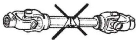
Diagram of two mechanical components with a crossed-out section, no text or symbols present

Alle roterende deler skal være skjermet

NO
2

Illustration of a paintbrush applying powder to stacked books (no text or symbols)

TRYKK PÅ PIN-koden

KULEKRAGE

KLEMMEBOLT

KLEMMEBOLT

VANLIG BORING OG N∅KKELBANG

SM∅RING:

DEMONTERE
Close-up of hands holding a small container with a logo, no visible text or symbols on the container itself

Close-up of hands holding a small container with a logo, no visible text or symbols

MONTASJE

  1. Smør sporet på åket.
  2. Sett nylonlageret inn i sporet på åket.

NO
Close-up of a mechanical connector or clamp component with no visible text or symbols

NO

Three mechanical components with no visible text or symbols, including a numbered label '24' in the top-left corner.

Metal mechanical component with flanged ends and a central hub, labeled with number 31 in the corner (no other text or symbols)

Metallic mechanical component with a U-shaped end and bolted joint (no text or symbols visible)

RA-OVERKJ∅RENDE CLUTSJ

FF-

FRIKSJONSMOMENTBEGRENSER
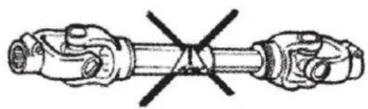
Diagram of two mechanical components with a crossed-out black line indicating a joint or connection (no text or symbols present)

Illustration of a paintbrush applying powder to stacked books (no text or symbols)

TRYCK PIN

BULKRAGE

KLÄMBOLT

KLÄMBOLT

VANLIG BORNING OCH KEYWAY

SMÖRJNING:

TA ISÄR
Close-up of hands holding a small container with a logo, no visible text or symbols on the container itself

MONTERING

SE

Close-up of a mechanical connector or clamp component with no visible text or symbols

Three industrial mechanical components with no visible text or symbols

Metal mechanical component with flanged ends and a central hub, labeled with number 31 in the corner (no other text or symbols)

Metallic mechanical component with a U-shaped end and bolted joint (no text or symbols visible)

RA-OMKÖPNING

FF-FRIKTIONS

MOMENTBEGRÄNSARE
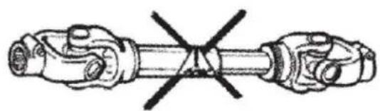
Diagram of two mechanical components with a crossed-out section, no text or symbols present

Illustration of a paintbrush applying powder to stacked books (no text or symbols)

ALFINETE DE PRESSÃO

COLAR DE BOLA

PARAFUSO DE GRAMPO

PARAFUSO DE GRAMPO

FURO PLANO E CHAVETA
16 8h 40h

LUBRIFICAÇÃO:

DESMANTELAR

Close-up of hands holding a small container with a logo, no visible text or symbols on the container itself

MONTAGEM

  1. Lubrifique a ranhura do jugo.
  2. Coloque o rolamento de nylon na ranhura do jugo.
Close-up of hands holding a small container with a logo, no visible text or symbols

PT
Close-up of a mechanical connector or clamp component with no visible text or symbols

PT

Three mechanical components with no visible text or symbols, including a numbered label '24' in the top-left corner.

Metal mechanical component with flanged ends and a central hub, labeled with number 31 in the corner (no other text or symbols)

Metallic mechanical component with a U-shaped groove and bolted end (no text or symbols visible)

RA-EMBREAGEM DE ULTRAPASSAGEM

Diagram of two mechanical components with a crossed-out section, no text or symbols present

Illustration of a paintbrush applying paint to stacked books (no text or symbols)

PUSH PIN

GULOVÝ GOLIER

SVORKA SVORKY

SVORKA SVORKY

HLADKÝ VÝTVOR A KLÚČOVÁ DRÁHA

MAZANIE:

DEMONTOVAŤ
Close-up of hands holding a small container with a logo, no visible text or symbols on the container itself

INŠTALÁCIA

Close-up of hands holding a small container with a logo, no visible text or symbols

SK

Three industrial mechanical components with no visible text or symbols

SKRÁTENIE HNACIEHO HRIADEL'A (Neodporúčame upravovat' naše produkty.)
Close-up of hands using a tool to handle a mechanical component (no visible text or symbols)

Metal mechanical component with flanged ends and a central hub (no visible text or symbols)

Metallic mechanical component with a U-shaped end and bolted joint (no text or symbols visible)

RA- PREDBEŽNÁ SPOJKA

OBMEDZOVAČ Krútiaceho momentu FF-TRENIA
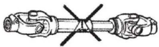
Diagram of two mechanical components with a crossed-out black line indicating a joint or connection (no text or symbols present)

Illustration of a paintbrush applying paint to stacked books (no text or symbols)

НАТИСНЕТЕ ПИН

ТОПКА ЯКА

СКОБЕН БОЛТ

СКОБЕН БОЛТ

ПЛАВ ОТВОР И ШПИЛКА

CMA3BAHE:

ДЕМОНТИРАНЕ

Close-up of hands holding a small container with a logo, no visible text or symbols on the object itself

ИНСТАЛАЦИЯ

BG

Close-up of a mechanical connector or clamp component with no visible text or symbols

BG

Three industrial mechanical components with no visible text or symbols

RA-ПРЕДВИДЕН СЪЕДИНИТЕЛ

ОГРАНИЧИТЕЛ НА ВЪРТЯЩИЯ МОМЕНТ ТИП SA-ТРЕСЧОТКА

FF-ФРИКЦИОНЕН ОГРАНИЧИТЕЛ НА ВЪРТЯЩИЯ МОМЕНТ
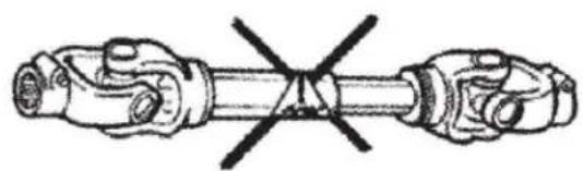
Diagram of two mechanical components with a crossed-out line indicating a joint or connection (no text or symbols present)

Illustration of a paintbrush applying paint to stacked books (no text or symbols)

PUSH PIN

КОЛАР МПАЛА

ΣΦΙΚΤΗΡΑΣ ΜΠΟΥΛ

ΣΦΙΚΤΗΡΑΣ ΜΠΟΥΛ
16 8h 40h

ΛΑΔΩΜΑ:

Close-up of hands connecting a mechanical component to a cylindrical part, no visible text or symbols

Close-up of hands holding a small container with a logo, no visible text or symbols on the object itself

ΑΠΟΓΥΜΝΩ

ΕΓΚΑΤΑΣΤΑΣΗ

EL

Close-up of a mechanical connector or clamp component with no visible text or symbols

EL

Three industrial mechanical components with no visible text or symbols

Metal mechanical component with flanged ends and a central hub, labeled with number 31 in the corner (no other text or symbols)

Metallic mechanical component with a U-shaped end and bolted joint (no text or symbols visible)

RA-ΣΥΜΠΛΕΚΤΗΣ ΥΠΕΡΒΑΣΗΣ

FF-ΠΕΡΙΟΡΙΣΤΗΣ ΡΟΠΗΣ ΤΡΙΒΗΣ
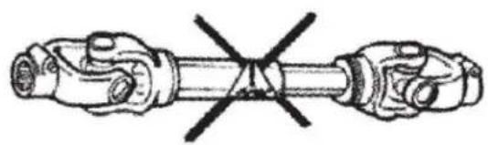
Diagram of two mechanical components with a crossed-out line indicating a joint or connection (no text or symbols present)

Nemojte raditi sa strojem bez pogonskog vratila, traktora i štitnika priključka. Štitovi pogonskog vratila moraju se slobodno okretati na pogonskom vratilu.

Isključite motor traktora i izvadite ključ prije nego što pristupite stroju ili obavite bilo kakvo održavanje
L L v2 L 4

Potvrdite minimalnu i maksimalnu radnu duljinu pogonske osovine.

Traktor mora biti spojen na stroj i postavljen tako da su kutovi zglobova minimalni i jednaki.
a1 a2 6

Illustration of a paintbrush applying paint to stacked books (no text or symbols)

STEZNI VIJAK

Gurnite jaram na PTO i umetnite vijak.

3D mechanical component with two side-view diagrams (no text or symbols)

STEZNI VIJAK

Gurnite jaram na PTO i umetnite vijak.

HR
Two metal bracket components: a 3D rendered part with circular hole and a 2D schematic symbol (no text or labels)

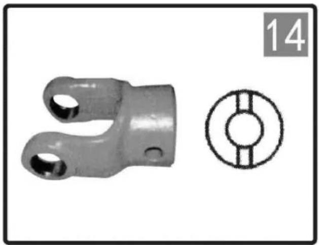
RAVNI PROVOR I ŽLJEB

Odaberite duljinu vijka na način da minimalizirate izbočenje.
Close-up of a mechanical device with a 8-hour mark and labeled number 15 (no text or symbols on the device itself)

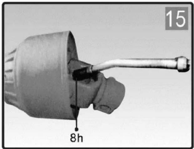
16 8h 40h

PODMAZIVANJE:

DEMONTIRAJ

Close-up of hands holding a small container with a logo, no visible text or symbols on the container itself

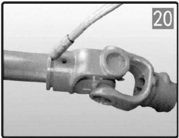
  1. Uklonite najlonski ležaj iz utora jarma.
  2. Ponovite gore navedene korake za drugu stranu.

HR
Close-up of a mechanical joint or connector with a coiled cable, no visible text or symbols

Close-up of hands holding a small container with a logo, no visible text or symbols

MONTAŽA

  1. Podmažite utor na jarmu.
  2. Stavite najlonski ležaj u utor na jarmu.

HR
Close-up of a mechanical connector or clamp component with no visible text or symbols

HR

Three industrial mechanical components with no visible text or symbols

  1. Očistite rubove pogonske cijevi turpijom i očistite sve strugotine s cijevi.

HR
Close-up of a hand using a tool to clean or wash a material, no visible text or symbols

RA-KVAČILO ZA PREMAKANJE

OGRANIČIVAČ ZAKRETNOG MOMENTA TIPA SA-RAČEGLICE

SB-OSMIČNI VIJAK OGRANIČAVAČ MOMENTA

Ovaj uređaj prekida prijenos snage smicanjem vijka kada zakretni moment premaši postavku. Zamijenite odrezani vijak s istim promjerom, duljinom i stupnjem kao original. Podmažite SB fitingom za podmazivanje najmanje jednom svake sezone i nakon razdoblja neuporabe.

HR
3D rendered mechanical component with springs and a central hub, no visible text or symbols

FF-FRIKCIJSKI LIMITER MOMENTA

Ograničava prijenos momenta na zadanu vrijednost. Nemojte mijenjati kompresiju opruge jer će to promijeniti postavke uređaja. Postavka zakretnog momenta se podešava povećanjem ili smanjenjem visine opruga. Za povećanje/smanjenje momenta podešavanje zategnite/otpustite osam matica za 1/4 kruga i provjerite radi li ispravno. Po potrebi ponoviti postupak. Izbjegavajte pretjerano zatezanje vijaka priključka, može doći do oštećenja traktora ili pogonskog sklopa.

LT

Parametras aprašymasParametras vertė
Produkto pavadinimasPTO velenas
ModelisWIE-PTO-235WIE-PTO-194WIE-PTO-141
Ilgis [cm]160 / 235127 / 194101 / 141
Svoris [kg]20.7612.3810.38
Produkto pavadinimasPTO velenas
ModelisWIE-PTO-114WIE-PTO-95WIE-PTO-72
Ilgis [mm]89 / 11474 / 9561 / 72
Svoris [kg]8.025.7213.52

Simple line drawing of a person standing on a bench with tools and equipment (no text or symbols)

Diagram of two mechanical components with a crossed-out section, no text or symbols present

Illustration of a paintbrush applying powder to stacked books (no text or symbols)

PUSH PIN

KAMULINÉ APYKLA

VARŽTAS

VARŽTAS

PAGRINDAS IR RAKTAS

TEPIMAS:

IŠDARYTI
Close-up of hands holding a small container with a logo, no visible text or symbols in the image.

MONTAVIMAS

Close-up of hands holding a small container with a logo, no visible text or symbols

LT

Three industrial mechanical components with no visible text or symbols

RA-VEIKIANTI MOKA

SA-RATCHET TIPO SUKIMO MOMENTO RIBOTUVAS

SB-SHEAR BOLT SUKIMO MOMENTO RIBOTUVAS

FF-TRINČIO SUKIMO MOMENTO RIBOTUVAS
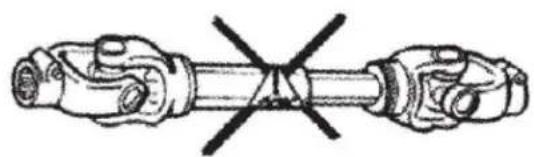
Diagram of two mechanical components with a crossed-out black line indicating a joint or connection (no text or symbols present)

Illustration of a paintbrush applying powder to stacked books (no text or symbols)

împingeti PIN

GULER BILĂ

Şurub de clemă

Şurub de clemă

LUBRIFICARE:

DEMONTAREA
Close-up of hands holding a small container with a logo, no visible text or symbols on the container itself

Close-up of hands holding a small container with a logo, no visible text or symbols

INSTALARE

RO

Three mechanical components with no visible text or symbols, including a numbered label '24' in the top-left corner.

Scurtarea arborelui de transmisie (Nu recomandăm modificarea produselor noastre.)
Close-up of hands using a tool to handle a mechanical component, no visible text or symbols

SA-LIMITATOR DE CUPLU TIP CLIC

SB-LIMITATOR DE CUPLUL ŞURBULUI DE FORFECARE

FF-LIMITATOR DE CUPLU DE FRICTIE
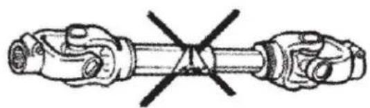
Diagram of two mechanical components with a crossed-out line indicating a joint or connection (no text or symbols present)

Illustration of a paintbrush applying powder to stacked books (no text or symbols)

POTISNI PIN

Potisnite zatič in potisnite jarem na kardansko gred, tako da se zatič zaskoči v utor na kardanski gredi. Prepričajte se, da se zatič vrne v prvotni položaj po pritrditvi na gred.
Mechanical component with two views: a circular cross-section showing internal gear teeth and a mechanical part with a curved handle (no text or symbols)

ŽOGALNI OVRATNIK

Potisnite ovratnico v odprt položaj. Potisnite jarem na utorno gred. Sprostite objemko in nastavljajte, dokler jarem ni pravilno pritrjen na gred.

SL
Two mechanical components: a cylindrical clamp and a shield-shaped bracket, both without any visible text or symbols.

OBJEMNI VIJAK

Potisnite jarem na priključno gred in vstavite vijak.
3D mechanical component with two side-view diagrams (no text or symbols)

OBJEMNI VIJAK

Potisnite jarem na priključno gred in vstavite vijak.

SL
Two mechanical components: a metal bracket with two holes and a circular inset showing a hole (no text or symbols)

GLAVNA IZVRTINA IN UTOR ZA KLJ

MAZANJE:

Potrebno je pogosto mazanje. Namažite dele pogonske gredi

RAZSTAVITE
Close-up of hands holding a small container with a logo, no visible text or symbols on the container itself

  1. Odstranite najlonski ležaj iz reže jarma.

  2. Ponovite zgoraj omenjene korake za drugo stran.

SL
Close-up of a mechanical joint or connector with a coiled cable, no visible text or symbols

NAMESTITEV

Close-up of hands holding a small container with a logo, no visible text or symbols

  1. Namažite režo na jarmu.
  2. Vstavite najlonski ležaj v režo jarma.

SL
Close-up of a mechanical connector or clamp component with no visible text or symbols

SL

Three mechanical components with no visible text or symbols, including a numbered label '24' in the top-left corner.

  1. Z pilico odstranite robove pogonske cevi in očistite vse opilke s cevi.

SL
Close-up of a hand using a tool to clean or wash material, no visible text or symbols

  1. Namažite notranjo pogonsko cev in ponovno sestavite zaščito na pogonsko gred.
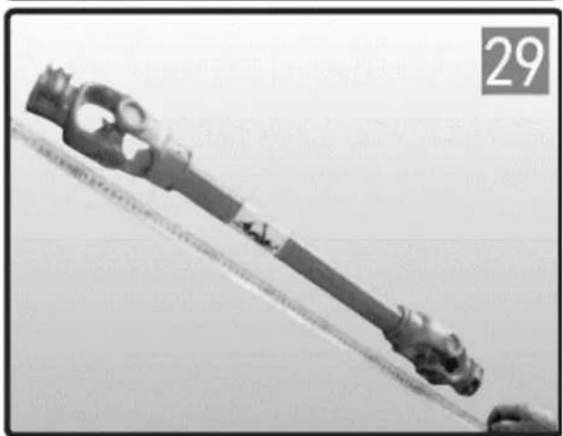
Close-up of a mechanical tool or device with a diagonal line extending from it, no visible text or symbols.

RA-PREHODNA SKLOPKA

OMEJEVALNIK NAVORA SA- RAGLJICE

Ta naprava prekine prenos moči, ko navor preseže nastavljeno.

SB-STRIŽNI OMEJEVALNIK NAVORA

FF-FRICIJSKI OMEJEVALNIK NAVORA

For the disposal of the device please consider and act according to the national and local rules and regulations.

CONTACT

expondo Polska sp. z o.o. sp. k.
Table of contents Click a title to access it
Manual assistant
Powered by Anthropic
Waiting for your message
Product information

Brand : Wiesenfield

Model : WIE-PTO-141

Category : Agricultural mechanical part