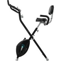
Drumfit WOD Rider Ultimate - Indoor bike trainer CECOTEC - Free user manual and instructions
Find the device manual for free Drumfit WOD Rider Ultimate CECOTEC in PDF.

| Product Type | Indoor cycling trainer (air bike) |
| Brand | Cecotec |
| Model | Drumfit WOD Rider Ultimate |
| Maximum user weight | 150 kg |
| Power supply | 2 AA 1.5 V batteries |
| Resistance | Air fan (air resistance) |
| Display type | LCD screen |
| Display functions | RPM, speed, time, distance, calories, power, heart rate |
| Training programs | Manual, Intervals 20/10, Intervals 10/20, Custom, Goals (time, distance, calories, heart rate) |
| Adjustments | Seat adjustable in height (8 positions) and forward/backward |
| Pedals | With adjustable straps |
| Included accessories | Bottle holder, tablet holder, transport wheels |
| Heart rate sensor | Integrated (handlebars) |
| Class | HC (domestic use) |
| Usage | Indoor only |
| Warranty | Contact Cecotec After-Sales Service |
| Maintenance | Soft damp cloth, regularly check screw tightness |
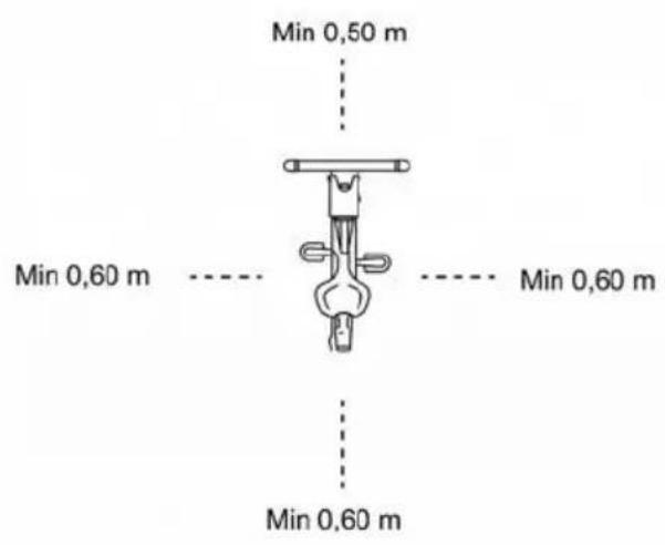
| Safety | Keep distances of 0.6 m around the device, do not use outdoors, stop if pain occurs |
| Recycling | Compliant with WEEE regulations, batteries to be disposed of separately |
Frequently Asked Questions - Drumfit WOD Rider Ultimate CECOTEC
User questions about Drumfit WOD Rider Ultimate CECOTEC
0 question about this device. Answer the ones you know or ask your own.
Ask a new question about this device
Download the instructions for your Indoor bike trainer in PDF format for free! Find your manual Drumfit WOD Rider Ultimate - CECOTEC and take your electronic device back in hand. On this page are published all the documents necessary for the use of your device. Drumfit WOD Rider Ultimate by CECOTEC.
USER MANUAL Drumfit WOD Rider Ultimate CECOTEC
natural_image
Exterior view of a modern exercise bike with visible branding and fan blade (no text or symbols on the device itself)SAFETY INSTRUCTIONS....4
ESPAÑOL....69
ENGLISH....84
FRANÇAIS....98
DEUTSCH....113
ITALIANO....129
PORTUGUÊS....144
NEDERLANDS....159
POLSKI....174
ČEŠTINA....189
MAGYAR....204
ΕΛΛΗΝΙΚΑ......219
TÜRKÇE 235
العربية 250
CATALÀ....262
FIGURES....276
NOTA
EU01_122512 Drumfit WOD Rider Ultimate
EN • The coding in this manual is generic and applies to all code variants of the appliance.
- Please read these instructions carefully before using the appliance. Keep this instruction manual for future reference or new users.
- Read the entire manual before assembling and using the machine. The product will only be safe if it is properly assembled, cared for and used correctly. It is your responsibility to make sure every user is informed about the warnings and precautions stated in this instruction manual.
- Before starting a training session, it is recommended that you consult your doctor if you have any adverse health or physical condition that may pose a risk to your safety or make it difficult to use the exercise bike properly. Your doctor's advice is essential if you are taking medication that affects your heart rate, blood pressure, or cholesterol level.
- Be aware of your body signals. Incorrect or excessive exercise can deteriorate your health. Stop exercising if you experience any of the following symptoms: pain, tightness in your chest, irregular heartbeat, extreme shortness of breath, dizziness, or nausea. If you experience any of these conditions, you should consult your doctor before continuing with your training.
- This machine can be used by children aged 8 years and above and persons with reduced physical, sensory, or mental capabilities or lack of experience and knowledge if they have been given supervision or instruction concerning the use of the machine in a safe way and understand the hazards involved. Children must not play with the machine. Cleaning and user maintenance must not be carried out by children without supervision.
- Keep children and animals away from the assembling area, as small parts could cause risk of suffocation if swallowed.
- Keep children and pets away from the machine. Do not allow children to use it and/or play with the machine. It is designed for adults only.
- Use the exercise bike on a solid, even surface with a protective cover for your floor or carpet.
- Ensure all screws and nuts are properly tightened before using the machine.
- The safety level of the machine can only be ensured through regular examination for damage or signs of wear and tear.
- Use the machine as indicated in this instruction manual. If you find any defective component while assembling or checking the machine, or if you hear any unusual noise coming from the equipment during use, stop using it. Do not use the equipment until the problem has been solved.
- Make sure you have enough space to lay out the parts before starting. Leave a free space of at least 0.6 m in front of all access areas of the machine in case of emergency. You can share the access areas with other machine nearby. Always ensure there are not any objects blocking the entrance and exit of the machine.
- Wear suitable clothing while using the machine. Avoid wearing loose clothing which may get caught in the equipment.
- WARNING: this training machine is not suitable for high-precision purposes. This equipment is HC class.
- WARNING: this machine operates by means of a flywheel. Be careful when in motion and ensure that it completely stops before getting down, as the inertia of the flywheel and pedals could cause injury to yourself or others.
• Maximum user weight: 150 kg. - It is not recommended for outdoor use.
- This machine is designed for domestic use only and is not intended for bars, restaurants, farmhouses, hotels, motels, and offices.
- The machine is not suitable for therapeutic use.
- Care must be taken when lifting or moving the equipment so as not to injure your back.
- WARNING: the heart rate sensors may be inaccurate, as it is not a medical device. Sensors can give you estimated heart rate information. If you feel any discomfort, stop exercising immediately. It may be dangerous for your health. If it persists, go immediately to the nearest medical centre.
- If repairs are required, please consult your supplier for further information or contact Cecotec Customer Service.
- If any parts protrude from the machine, they may interfere with the user's movement.
Instructions on batteries
- Do not burn or expose the batteries to high temperatures, as they may explode.
- Leaks from the batteries can occur under extreme conditions. Do not touch any liquid that leaks from the batteries. If the liquid comes into contact with skin, wash immediately with soap and water. If the liquid gets into the eyes, rinse them immediately with clean water for at least 10 minutes and seek medical attention. Wear gloves to handle the battery and dispose of it immediately in accordance with local regulations.
- Avoid contact between the batteries and small metal objects such as paper clips, coins, keys, nails, or screws.
- Do not tamper with the batteries in any way.
- The batteries must be removed for safe disposal of the machine.
- Keep the batteries out of the reach of children when there is a risk of ingestion.
- Battery ingestion can cause burns, soft-tissue perforation, and death. It can cause severe burns within two hours of the ingestion.
- In case of battery ingestion, please seek medical help immediately.
- The batteries' power supply terminals must not be short-circuited.
- If the machine is to be stored for a long period of time, it is advisable to remove the batteries.
- The batteries must be inserted in the correct position. Check polarity when replacing them.
1. Parts and components
Hardware and tools package:
Fig. 1
| No. | Description | Qty |
| 3 | M5×40×15×010 | 4 |
| 4 | M4×40×20×20×010.5 | 4 |
| 22 | Handlebar end cap | 2 |
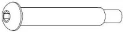
| 23 | Screw | 2 |
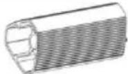
| 24 | Aluminium support tube | 2 |
| 45 | 5×013×1 | 4 |
| A | S5 | 1 |
| B | S6 | 1 |
| C | S8 | 1 |
| D | S13-15 | 1 |
Complete parts list:
Note:
The graphics in this manual are schematic representations and may not exactly match the product.
Fig. 2
| No. | Description | Qty | No. | Description | Qty |
| 1 | Console | 1 | 54 | Small crank | 2 |
| 2 | Tablet holder | 1 | 55 | M10 nut (H7, S17 spanner) | 2 |
| 3 | M5×40×15×010 screw assembly | 4 | 56 | D25 spring | 3 |
| 4 | M4×40×20×010.5 screw assembly | 4 | 57 | 6005 bearing | 2 |
| 5 | Console support | 1 | 58 | ∅25.1×∅30× 4 spacer | 2 |
| 6 | Bottle holder | 1 | 59 | D25×∅31×0. 3 curved washer | 2 |
| 7 | M8×20 screw (Allen S5) | 8 | 60 | M6 nylon nut (H6, S10 spanner) | 8 |
| 8 | D8 spring washer | 12 | 61 | D6 spring washer | 8 |
| 9 | D8×∅20×2 washer | 11 | 62 | Magnet | 2 |
| 10 L/R | Left/right handlebar | 2 | 63 | Drive belt plate | 1 |
| 11 | Saddle | 1 | 32 | End cap | 4 |
| 12 | End cap 2 | 1 | 64 | Shaft | 1 |
| 13 | Saddle mounting plate | 1 | 65 | M6×16 screw (S10 spanner) | 8 |
| 14 | End cap 1 | 1 | 66 | Swing plate | 2 |
| 15 | M6×8 screw(Allen S5) | 2 | 67 | M8×16screw (S13 spanner) | 8 |
| 16 | Saddle end cap | 1 | 68 | Connector | 2 |
| 17 | Saddle end cap | 1 | 69 | 6003 bearing | 2 |
| 18 | Upper knob block | 1 | 70 | D35 spring | 2 |
| 19 | Saddle post | 1 | 71 | D8×Ø22×2 washer | 2 |
| 20 | L-type handle | 1 | 72 | Cover | 2 |
| 21 | M8×20 screw (Allen S6) | 6 | 73 | M12×1 nut (H7, S16 spanner) | 2 |
| 22 | Handlebar end cap | 2 | 74 | Chain screw | 2 |
| 23 | Screw | 2 | 75 | M12×1 nut (H6, S19 spanner) | 2 |
| 24 | Aluminium support tube | 2 | 76 | 6201 bearing | 2 |
| 25 | M8×45×15 screw (Allen S5) | 2 | 77 | D12×Ø15.5× 0.3 curved washer | 1 |
| 26 | 608 bearing | 2 | 78 | Ø18×D12.1× 59 spacer | 1 |
| 27 | Transport wheels | 2 | 79 | Shaft | 1 |
| 28 | M8 nylon nut (H7.5, S13 spanner) | 2 | 80 | Fan assembly | 1 |
| 29 | M10×20 screw (Allen S6) | 6 | 81 | Sleeve | 1 |
| 30 | D10 spring washer | 4 | 82 | Ø18×D12.1× 34.5 spacer | 1 |
| 31 | D10×Ø20×2 washer | 4 | 83 | Grille cover 1 | 1 |
| 32 | Stabiliser caps | 2 | 84 | Grille cover 2 | 1 |
| 33 | Front stabiliser | 1 | 85 | Grille cover 3 | 1 |
| 34 | M8 nut (H5.5, S14 spanner) | 4 | 86 | Deflector hood | 1 |
| 35 | Adjustable foot | 4 | 87 | Fan blade 1 | 12 |
| 36 | Rear stabiliser | 1 | 88 | Fan blade 2 | 4 |
| 37 | Main frame | 2 | 89 | Fan blade plate | 4 |
| 38 L/R | Left/right pedal | 2 | 90 | Drive belt | 1 |
| 39 | Crank cover | 2 | 91 | M6×10 screw (S10 spanner) | 1 |
| 40 | M10×1.25 nut(H7.5, S14 spanner) | 2 | 92 | D6×Ø13×1.5washer | 1 |
| 41 L/R | Left/right flywheel | 2 | 93 | Tensioner | 1 |
| 42 L/R | Left/right crank | 2 | 94 | Tensioner shaft | 1 |
| 43 | ST4.2×16×08 self-tapping screw | 8 | 95 | Bush | 1 |
| 44 | ST4.2×19×08 self-tapping screw | 9 | 96 | L-type handle | 2 |
| 45 | D5×013×1 washer | 10 | 97 | Sensor holder | 1 |
| 46 | ST4.2×10×08 self-tapping screw | 8 | 98 | Sensor | 1 |
| 47 L/R | Left/right chain cover | 2 | 99 | ST4.2×16×010.5 self-tapping screw | 16 |
| 48 | D42 spring | 2 | 100 | Main cable | 1 |
| 49 | D20 spring | 2 | 101 | 012×11×03 cable grommet | 2 |
| 50 | 6004 bearing | 2 | 102 | Packing tube | 2 |
| 51 | Crank/connecting rod | 2 | 103 | M6 nylon nut (H6, S10 spanner) | 1 |
| 52 | D10×032×2 washer | 2 | 104 | D5×016×1.5 washer | 16 |
| 53 | M10×50×20 screw (S17 head) | 2 | 105 | ST4.2×13×08 self-tapping screw | 2 |
2. Before use
- This appliance comes in a packaging designed to protect it during transport. Remove the appliance from its box. You can keep the original box and other packaging materials in a safe place to prevent damage to the appliance if you need to transport it in the future. If you wish to dispose of the original packaging, make sure all items are recycled properly.
ENGLISH
- Check that all parts and components are included and in good condition. If any of them are missing or damaged, please contact Cecotec's Official Technical Support Service immediately.
Box content:
Air bike
- 2 x 1.5V AA batteries
- Instruction manual
- Do not remove the product's serial number in order to keep proper traceability if technical assistance is required.
3. Assembly
Step 1. Stabiliser assembly
Fig. 3
a. Remove the M10×20 screws (29), D10 spring washers (30), D10×020×2 washers (31) and packing tubes (102) from the main frame (37) using the S6 Allen key (B). These fixings come pre-installed.
b. Position the front stabiliser (33) and rear stabiliser (36) on the main frame (37). At each fixing point, assemble the following stack: M10×20 screw (29), D10 spring washer (30) and D10×020×2 washer (31). Tighten with the S6 Allen key (B) until clearance is eliminated, then perform final tightening in alternating sequence.
Step 2. Saddle assembly
Fig. 4
a. Loosen the L-type handle (96) by turning anticlockwise. Insert the saddle post (19) into the main frame (37) to the desired height, then tighten the L-type handle (96) by turning clockwise to lock the saddle post (19) in the main frame (37).
b. Mount the saddle (11) on top of the saddle post (19) and secure firmly with the S13–15 spanner (D).
c. Refer to the "Saddle adjustment" section for steps to adjust the saddle height and fore/aft position.
Step 3. Stem assembly and sensor connection
Fig. 5.
a. Remove the M8×20 screws (7), D8 spring washers (8) and D8×∅20×2 washers (9) from the main frame (37) using the S5 Allen key (A). These fixings come pre-installed.
b. Connect the sensor (98) to the main cable (100). Ensure the connector is fully inserted without clearance. Route the cables inside the main frame (37) to
ENGLISH
prevent pinching in the next step.
c. Insert the console support (5) into the main frame (37), aligning the holes. Secure the assembly with the M8×20 screws (7), D8 spring washers (8) and D8×020×2 washers (9) and tighten with the S5 Allen key (A) until clearance is eliminated. Recommended torque for M8: 18–22 N·m.
Step 4. Handlebar and support tube assembly
Fig. 6.
a. Position the left/right handlebars (10L/10R) on the main frame (37). Remove the pre-installed M8×20 screws (21) with the S6 Allen key (B), position the handlebars and refit the M8×20 screws (21) with their D8 spring washers (8) where appropriate. Tighten in alternating sequence until clearance is eliminated.
b. Secure the aluminium support tube (24) to the main frame (37) using the screws (23). Tighten with the S8 Allen key (C) until firmly fixed.
c. Insert the handlebar end cap (22) into the aluminium support tube (24).
Step 5. Console, tablet holder and pedal assembly
Fig. 7
a. Remove the pre-installed M5×40×15×010 screw assemblies (3) and M4×40×20×010.5 screw assemblies (4) from the console (1) and tablet holder (2) using the S5 Allen key (A).
b. Connect the main cable (100) to the console cable. Ensure the connector is fully inserted without clearance. Route the cable through the interior of the console support (5).
c. Secure the console (1) and tablet holder (2) to the console support (5) using the M5×40×15×010 screw assemblies (3) with the D5×013×1 washers (45) and the M4×40×20×010.5 screw assemblies (4). Tighten with the S5 Allen key (A) until firmly fixed.
d. Remove the pre-installed M5×40×15×010 screw assemblies (3) from the console support (5). Position the bottle holder (6) on the console support (5) and secure by reusing the screw assemblies (3). Tighten with the S5 Allen key (A).
e. Thread the right pedal (38R) into the right crank (42R) and the left pedal (38L) into the left crank (42L). Tighten with the S13–15 spanner (D). The left pedal (38L) has reverse thread: thread anticlockwise. Recommended torque: 35–45 N·m.
Moving the machine
Fig. 8
To move the bike, lift the left/right handlebar (10L/10R) until the transport wheels (27) of the front stabiliser (33) contact the floor. With the wheels in contact, move the equipment to the desired location by tilting gently from the main frame (37).
Saddle adjustment
Fig. 9
Height:
ENGLISH
a. Loosen the L-type handle (96) by turning anticlockwise.
b. Slide the saddle post (19) to the desired position, aligning one of the 8 holes with the reference mark on the post.
c. Do not exceed the "MAX" mark on the saddle post (19).
d. Tighten the L-type handle (96) by turning clockwise until the saddle post (19) is firmly locked in the main frame (37).
Fore/aft position:
a. Loosen the L-type handle (20) on the saddle mounting plate (13).
b. Slide the saddle (11) forwards or backwards following the guide arrows on the seat mounting plate (13) until achieving the appropriate distance.
c. Tighten the L-type handle (20) clockwise to fix the position.
4. Operation
Console display functions
| Indicator | Description |
| RPM | Shows the revolutions per minute. Range: 0–199. |
| SPEED | Shows the current training speed. Maximum speed: 99.9 km/h or mph (depending on the selected unit). To change between Kilometres and Miles units, press ENTER and START simultaneously for 2 seconds, then use the arrow keys to change between km/h and mph. |
| TIME | Count up: without preset time, time advances from 00:00 to maximum 1:59:59.Count down: if a target time is set, the console (1) counts down from the set value to 00:00:00. The time setting is made in 1-minute increments/decrements (range 0:00–1:59:00). |
| DISTANCE | Accumulates total distance from 0.0 to 999.5 km/ML or counts down from a target value. The distance setting is made with UP/DOWN keys in 0.5 km or ML steps. |
| CALORIES | Accumulates calories from 0 to maximum 999 or counts down from a target calorie value. The setting is made with UP/DOWN keys. The countdown can be set up to 990. |
| WATT | Shows the real-time power (W) during training. Display range: 0–1999 W. |
| PULSE | Allows setting a target age between 0 and 99 years. Based on age, a target heart rate is established. When actual heart rate exceeds the target value, the console emits a beep. Range: 0–240 bpm. |
Button functions
| Button/Key | Function |
| START | Quickly start training or resume from pause. |
| STOP | Temporarily stop or resume from Stop. Clear all settings. Press and hold for 2 seconds to reset the console. |
| DOWN (▼) | Decrease Distance, Calories, Time and Age values. |
| UP (▲) | Increase Distance, Calories, Time and Age values. |
| Target Distance | Direct access to Distance target mode. |
| Target Calories | Direct access to Calories target mode. |
| Target Heart-rate | Direct access to Heart Rate target mode. Based on your age, the console sets your target heart rate. |
| Target Time | Direct access to Time target mode. |
| Interval | Selection of interval programmes: INTERVAL 10/20, INTERVAL 20/10 and Custom. |
| ENTER | Confirm settings or enter the selected programme. |
Initial operating instructions
-
Upon power-on, the LCD display shows all segments and emits a long beep.
-
Subsequently, the DIST area shows the flywheel diameter for configuration. After this step, the console enters AGE setting mode and the age value flashes.
-
Use the UP/DOWN keys to set the desired age and press ENTER to confirm. The console enters standby mode.
- In display/setting modes, the display labels flash sequentially every 1 second to indicate the active element. The cycle includes: INTERVAL 10/20, INTERVAL 20/10, INTERVAL Custom, READY, WORK, REST, TIME, DISTANCE, CALORIES, WATT(S), SPEED, RPM and the DOWN icon.
- If no key press, RPM signal (pedalling), or pulse signal is detected for 60 seconds, the Console enters sleep mode.
- Programme selection: Manual, 20/10 and 10/20 intervals.
4.1 Manual mode
- From standby, press START to begin exercise. A 1-second beep sounds and the TIME, DISTANCE, CALORIES, WATT, SPEED and RPM counters begin counting upwards.
● PULSE: if the Console receives pulse signal, the icon illuminates and displays the heart rate value. Without signal, "P" appears.
- Pause: press START during training to pause. The console emits a brief beep every 30 seconds and the values remain visible, flashing every 1 second. If paused for 5 minutes, a 2-second beep sounds and the console returns to standby mode. Press START to resume.
- End/STOP: press STOP to finish. TIME shows the total time; DISTANCE shows the total distance; CALORIES shows the total calories. WATT, SPEED and RPM alternate between AVG and MAX readings. PULSE window alternates 65% and 85% MAX every 5 seconds. With pulse signal, PULSE shows the actual pulse; without signal, no value is displayed.
- You may press any PROGRAM key (Target Distance, Target Calories, Target Heart-rate, Target Time or Interval) to enter the corresponding programme.
4.2 20/10 Intervals programme
- Selection: press the INTERVAL 20/10 key. The "20/10" indicator lights up and a 1-second long beep sounds.
- Initial countdown: 3→0; a beep sounds per second and READY flashes.
● Work phase: countdown 20→0 with WORK flashing once per second. The TIME, DISTANCE, CALORIES, WATT, SPEED and RPM indicators calculate in real time. - Rest phase: countdown 10→0 with REST flashing and beeps per second. READY flashes during the last 3 seconds of each phase.
- Cycles: the cycle counter increases by 1 per cycle (WORK+REST) until showing 08/08. Upon completion, the end display is showed.
- Pause/STOP: as in Manual mode. STOP or programme end: 1-second beep and for \~30 seconds, the totals display (TIME, DISTANCE, CALORIES) and AVG/MAX alternate for WATT, SPEED and RPM. PULSE alternates 65% and 85% MAX every 5 seconds. With pulse signal, PULSE shows the actual pulse; without signal, no value is displayed.
● To start another programme, press a PROGRAM key.
4.3 10/20 Intervals programme
- Selection: press the INTERVAL 10/20 key. The "10/20" indicator lights up and a 1-second long beep sounds.
- Initial countdown: 3→0; a beep sounds per second and READY flashes.
● Work phase: countdown 10→0 with WORK flashing. - Rest phase: countdown 20→0 with REST flashing and beeps. READY flashes during the last 3 seconds of each phase.
- Cycles: the counter increases by 1 per cycle until 08/08 and proceeds to the end display.
● Pause/STOP and summary display: same as 20/10.
● To start another programme, press a PROGRAM key.
4.4 Custom interval programme
Pre-settings
- Select the mode: press the INTERVAL key until "Custom" lights up.
● Number of cycles: "00/XX" will flash. Use the UP/DOWN keys to set the total cycles between 01 and 99 (circular advance). Press ENTER to confirm.
● WORK time: with TIME illuminated and WORK flashing, set the work time between 0:01 and 9:59 with UP/DOWN (circular advance). Press ENTER to confirm. - REST time: with TIME illuminated and REST flashing, set the rest time between
ENGLISH
0:01 and 9:59 with UP/DOWN (circular advance). Press ENTER to confirm. A 1-second beep sounds.
Training start and development
- Countdown: the console performs 3→0 countdown with a beep per second and READY flashing.
- Work phase: WORK time countdown begins; WORK flashes once per second. The TIME, DISTANCE, CALORIES, WATT, SPEED and RPM indicators calculate in real time. The cycle display shows "01/XX" (current/total cycle).
- Rest phase: REST time countdown begins; REST flashes once per second and a beep sounds per second. READY flashes during the last 3 seconds of each phase.
- Repetitions: phases 2 and 3 repeat and the cycle counter increases by +1 upon completing each REST, until the programmed total (XX) is complete. The console then displays the end page.
Pause, resume and end
- Pause: press START to pause. During pause, a 0.5-second beep sounds every 30 seconds. If 5 minutes elapse without resuming, a 2-second beep sounds, and the console goes to standby mode. Press START to resume.
- STOP/End: upon completing the cycles or pressing STOP, a 1-second beep sounds and for \~30 seconds, the totals display (TOTAL TIME, DISTANCE, CALORIES). WATT, SPEED and RPM alternate AVG/MAX every 5 seconds. PULSE shows the actual pulse if there is signal; otherwise alternates 65% and 85% MAX.
4.5 Target Time mode
- In standby mode, press the Target Time key. The TIME label light ups and a long 1-second beep sounds.
- When TIME flashes, set it with the UP/DOWN keys and confirm with ENTER. TIME remains steadily illuminated.
- Upon starting, the target time counts down. The DISTANCE, CALORIES, WATT, SPEED and RPM indicators begin counting upwards.
- Pause: press START to pause. When paused, a 0.5-second beep sounds every 30 seconds, and the values flash every 2 seconds. If paused for 5 minutes, a 2-second beep sounds and the console switches to standby. Press START to resume.
- No pedal signal for 30 seconds, a short beep sounds and the console goes into standby.
- End/STOP: upon reaching the target or pressing STOP, TIME shows the total time; DISTANCE shows the total distance; CALORIES shows the total consumption. WATT, SPEED and RPM alternate AVG/MAX every 5 seconds.
- With pulse signal, PULSE shows the instantaneous value; without signal, no value is displayed.
- Press any PROGRAM key to select another programme.
4.6 Target Distance mode
- In standby mode, press the Target Distance key. The DISTANCE label light ups and a long 1-second beep sounds.
- When DISTANCE flashes, set it with the UP/DOWN keys and confirm with ENTER.
- Upon starting, DISTANCE counts down from the preset value. The TIME, CALORIES, WATT, SPEED and RPM indicators count upwards.
- Pause: press START to pause. When paused, a 0.5-second beep sounds every 30 seconds, and the values flash every 2 seconds. If paused for 5 minutes, a 2-second beep sounds and the console switches to standby. Press START to resume.
- No pedal signal for 30 seconds, short beep and switch to standby.
- End/STOP: TIME shows the total time; DISTANCE shows the total distance; CALORIES shows the total consumption. WATT, SPEED and RPM alternate AVG/MAX every 5 seconds.
- PULSE: shows the actual pulse if there is signal; otherwise empty.
- Press any PROGRAM key to select another programme.
4.7 Target Calories mode
- In standby mode, press the Target Calories key. The CALORIES label light ups and a long 1-second beep sounds.
- When CALORIES flashes, adjust the target with UP/DOWN and confirm with ENTER.
- Upon starting, CALORIES counts down from the set value. The TIME, DISTANCE, WATT, SPEED and RPM indicators count upwards.
- Pause: press START to pause. When paused, a 0.5-second beep sounds every 30 seconds, and the values flash every 2 seconds. If paused for 5 minutes, a 2-second beep sounds and the console switches to standby. Press START to resume.
- No pedal signal for 30 seconds, short beep and switch to standby.
- End/STOP: TIME shows the total time; DISTANCE shows the total distance; CALORIES shows the total consumption. WATT, SPEED and RPM alternate AVG/MAX every 5 seconds.
- PULSE: shows the actual pulse if there is signal; otherwise it remains without value.
- Press any PROGRAM key to select another programme.
- When CALORIES flashes, adjust it with UP/DOWN and confirm with ENTER. CALORIES is permanently illuminated.
- During training, TIME, DISTANCE, WATT, SPEED and RPM count up from 0.
- Pause: press START to pause. When paused, a 0.5-second beep sounds every 30 seconds, and the values flash every 2 seconds. After 5 minutes of pause, a 2-second beep sounds and the console switches to standby. Press START to resume.
- No pedal signal for 30 seconds, a short beep sounds, and the console goes into
ENGLISH
standby.
-
Upon reaching the target or pressing STOP, TIME shows the total time; DISTANCE shows the total distance; CALORIES shows the total consumption. WATT, SPEED and RPM alternate AVG/MAX every 5 seconds.
-
PAUSE: with heart rate signal, it shows the actual heart rate; without signal, no value is displayed.
4.8 Target Heart Rate mode
- In standby mode, press the Target Heart-Rate key. AGE and the heart rate icon illuminate; a long 1-second beep sounds.
- When AGE flashes, set your age with UP/DOWN and confirm with ENTER. AGE and the heart rate icon are illuminated.
- Start training. The Console automatically calculates your MAX HR and displays the 65% and 85% thresholds. TIME, DISTANCE, CALORIES, WATT, SPEED and RPM start counting.
- Low Zone: If your pulse rate drops below 65% of MAX HR, "65%" will flash and the console will beep every 10 seconds until it returns above 65%.
- High Zone: if your pulse exceeds 85% of MAX HR, the value "85%" will flash and the console will beep every 10 seconds until it returns below 85%.
- If there is no pulse signal for 30 seconds, a short beep will sound, and the console will enter standby.
- Pause: press START to pause. When paused, a 0.5-second beep sounds every 30 seconds, and the values flash every 2 seconds. After 5 minutes of pause, a 2-second beep sounds and the console switches to standby. Press START to resume.
- End/STOP: upon completion (or pressing STOP), TIME displays the total time; DISTANCE displays the total distance; CALORIES displays the total calories burned. WATT, SPEED and RPM alternate AVG/MAX every 5 seconds.
- Press any PROGRAM key to select another programme.
Console settings and states
SETTING mode (units change)
- Press and hold the START + ENTER keys for 2 seconds. A long beep will sound. The SPEED label will be lit and the unit will flash.
- Select the unit with UP/DOWN: km/h or mph. Press ENTER to confirm. The distance units link automatically (km with km/h; mi with mph).
- If no action is taken for 30 seconds, the console returns to standby mode.
RESET mode (total reset)
- In any mode, press and hold the STOP key for 2 seconds to perform a hard reset.
- The LCD flashes every 2 seconds and a 2-second beep sounds.
- The console returns to standby mode with default values (session settings and active targets are reset).
SLEEPING mode
- In standby mode, if there is no key press or RPM/pulse signal for 60 seconds, the Console goes into Sleeping mode.
● To exit Sleeping, pedal or press any key (e.g. START).
5. Exercise guidelines
A proper workout should consist of the following phases:
● Warm-up: 5-10 minutes of stretching and low-intensity exercise. A proper warm-up increases body temperature, heart rate and circulation, preparing you for exercise. Fig. 10
● Training: 20-30 minutes of exercise.
(Note: during the first weeks of training, do not maintain a high heart rate for more than 20 minutes). Fig. 11
● Cool-down: 5-10 minutes of stretching. This increases flexibility and helps prevent post-exercise injuries. Fig. 10
Workout routine
To maintain or improve fitness, complete three workout sessions weekly, with at least one day's rest between sessions. After several months of training, you may increase to five sessions weekly. Consistency is key for optimal results.
6. Cleaning and maintenance
- To clean the bike use a soft, damp cloth. Do not use abrasive cleaning agents or solvents to clean plastic parts. Wipe off any perspiration that may remain on the bike after each use. Be careful not to allow too much moisture to enter the console display, as this may create a risk of electric shock or cause failure of electrical components.
- Please keep the air bike, especially the console, away from direct sunlight to prevent damage to the display.
- Check weekly and before each use that all mounting bolts and the machine pedals are tightened securely.
● Store the air bike in a clean and dry place, out of the reach of children and pets.
7. Technical specifications
Product: Drumfit WOD Rider Ultimate
Product reference: EU01_122512
Power supply for display: 2 x 1.5V AA batteries
Maximum user weight: 150 kg.
Class: HC
Technical specifications may change without prior notice to improve product quality.
Made in China | Designed in Spain
8. Recycling of electrical and electronic equipment

This symbol indicates that, according to the applicable regulations, the product and/or battery must be disposed of separately from household waste. When this product reaches the end of its shelf life, you should dispose of the batteries/accumulators and take them to a collection point designated by the local authorities.
For detailed information on how to properly dispose of electrical and electronic equipment and/or the corresponding batteries, consumers should contact their local authorities.
Information regarding national packaging recycling systems and their marking can be found on our website.
Compliance with the above guidelines will help protecting the environment.
9. Technical support and warranty
Cecotec shall be liable to the end user or consumer for any lack of conformity that exists at the time of product delivery under the terms, conditions and deadlines established by applicable regulations.
Repairs should be carried out by qualified personnel.
If at any moment you detect any problem with your product or have any doubt, do not hesitate to contact the official Cecotec Technical Support Service at +34 96 321 07 28.
10. Copyright
The intellectual property rights over the texts in this manual belong to CECOTEC INNOVACIONES, S.L. All rights reserved. The content of this publication may not, either in part or in its entirety, be reproduced, stored in a retrieval system, transmitted or distributed by any means (electronic, mechanical, photocopying, recording or similar) without prior authorisation from CECOTEC INNOVACIONES, S.L.
11. Simplified EU Declaration of Conformity

Cecotec Innovaciones hereby declares that this appliance complies with the essential requirements and other relevant provisions of the regulations applicable in the European Union. This appliance has been designed, manufactured and tested in compliance with required safety and quality standards. The full text of the EU Declaration of
Conformity can be found on the following website:
https://cecotec.es/es/information/declaration-of-conformity
FRANÇAIS
4.6 Mode Distance cible (Target DISTANCE)
https://storececotec.it/it/information/declaration-of-conformity
PORTUGUÊS
https://cecotec.pt/pt/information/declaration-of-conformity
NEDERLANDS
Product: Drumfit WOD Rider Ultimate
Productreferentie: EU01_122512
https://cecotec.es/es/information/declaration-of-conformity
ČEŠTINA
https://cecotec.es/es/information/declaration-of-conformity
FIGURES
FIG 1:
| 3 | 22 |
 |  |
| 4 | 23 |
 |  |
| 24 | 45 |
 |  |
| A | B |
 |  |
| C | D |
 |  |
FIG 2:
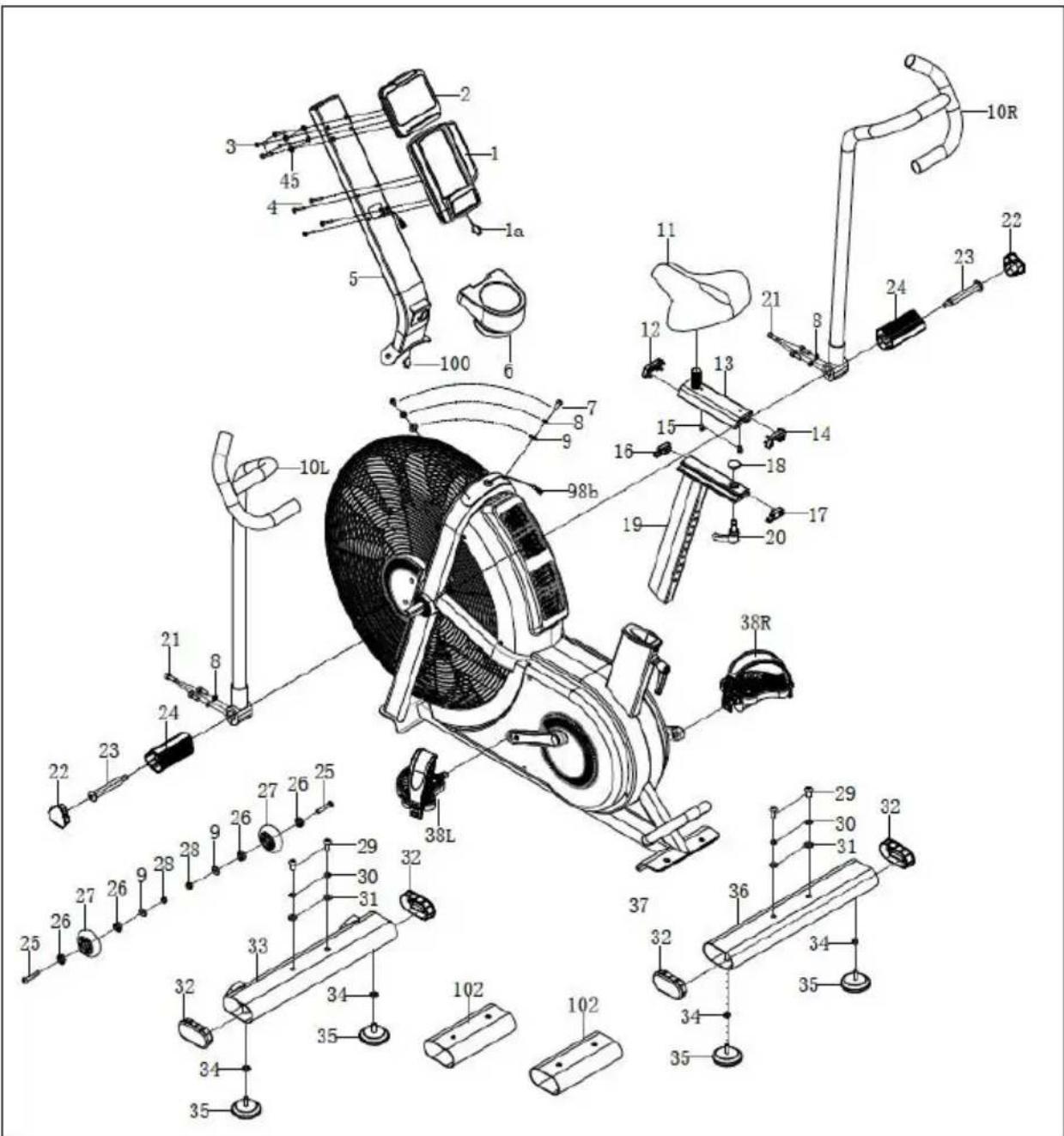
FIG 3:
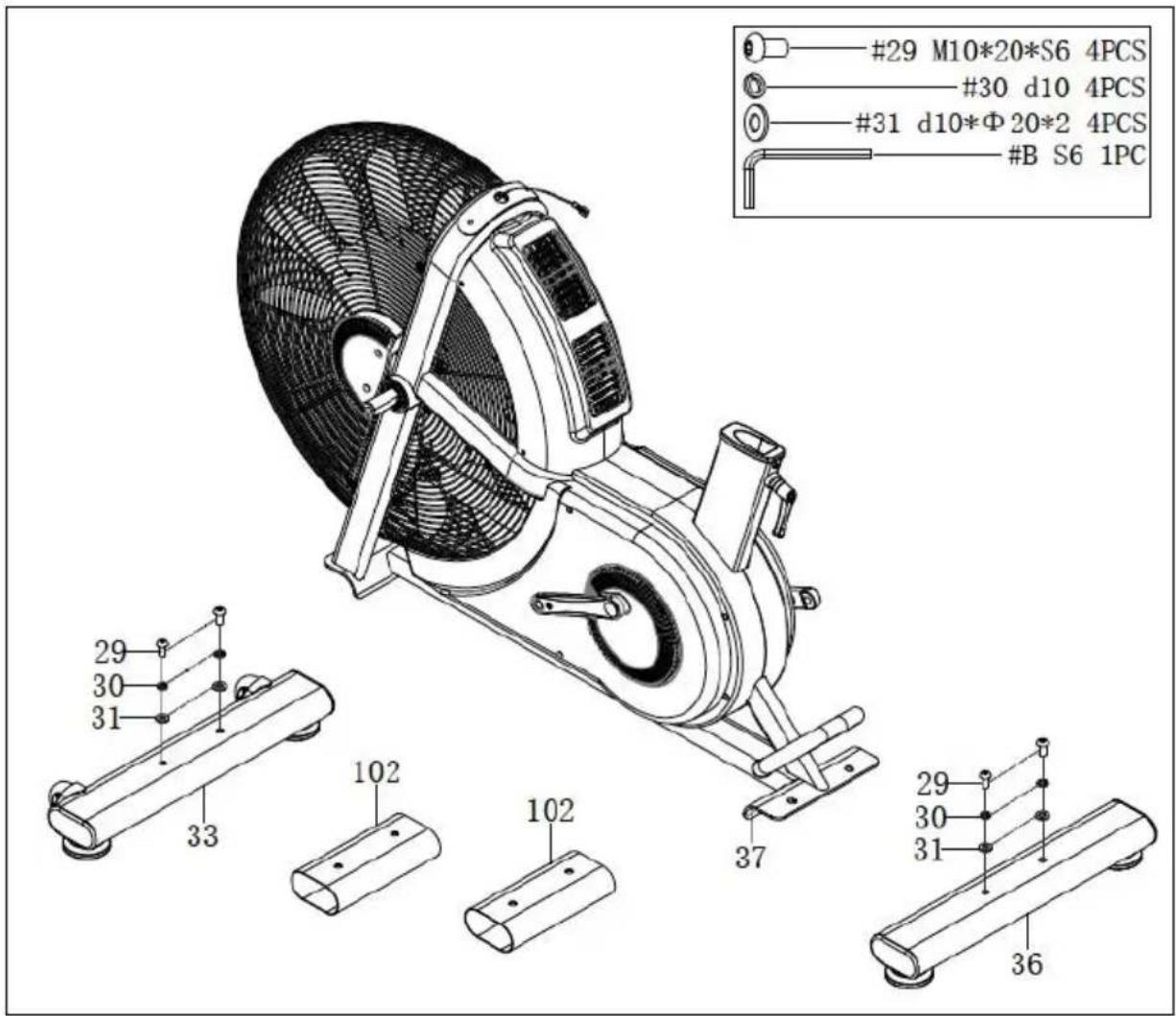
FIG 4:
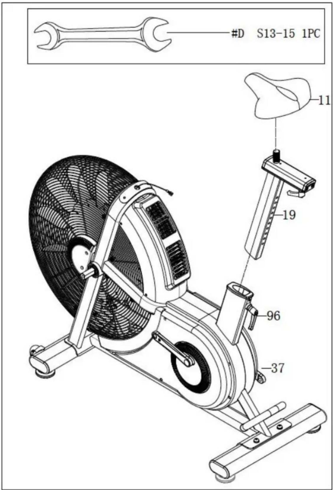
FIG 5:
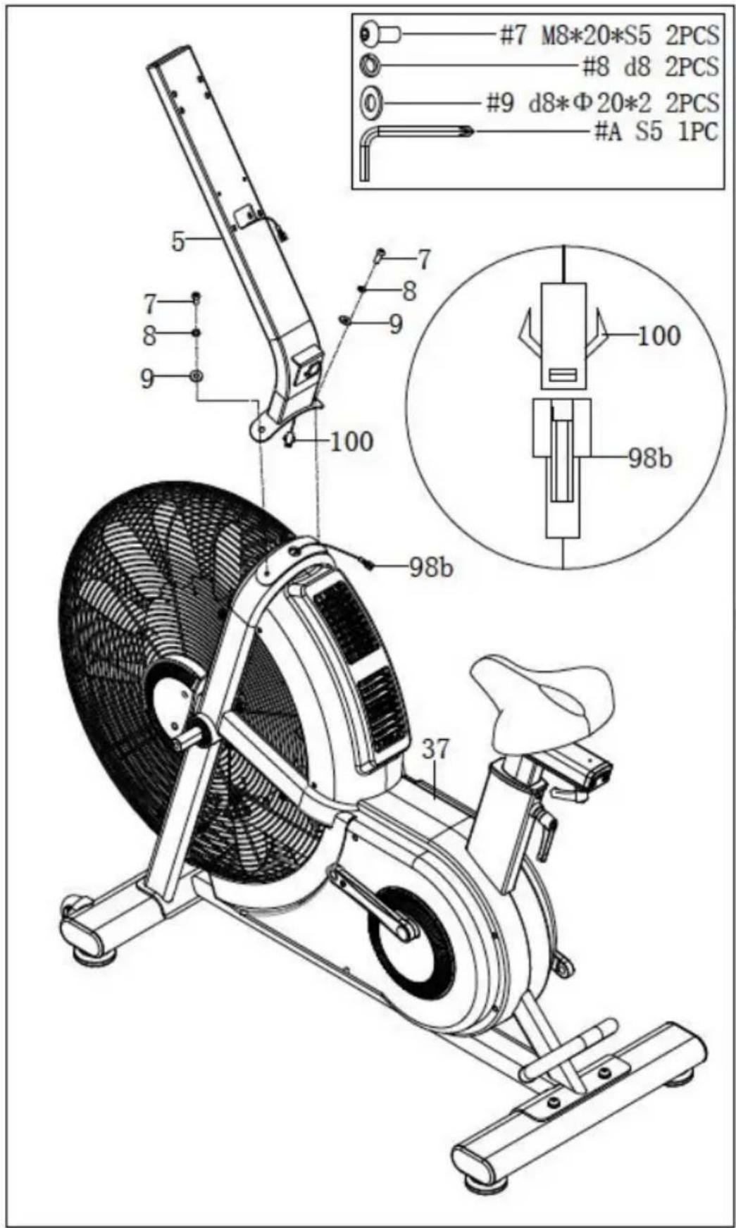
FIG 6:
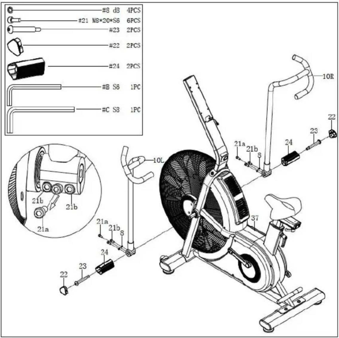
FIG 7:
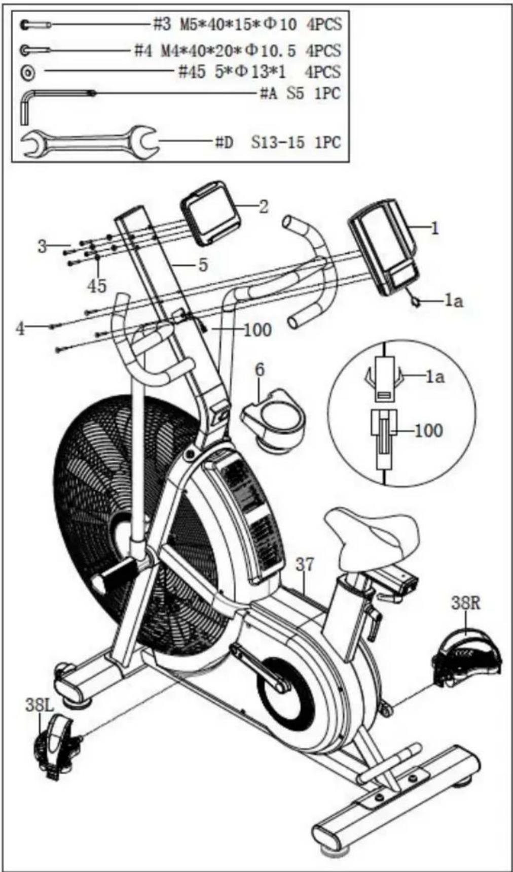
FIG 8:
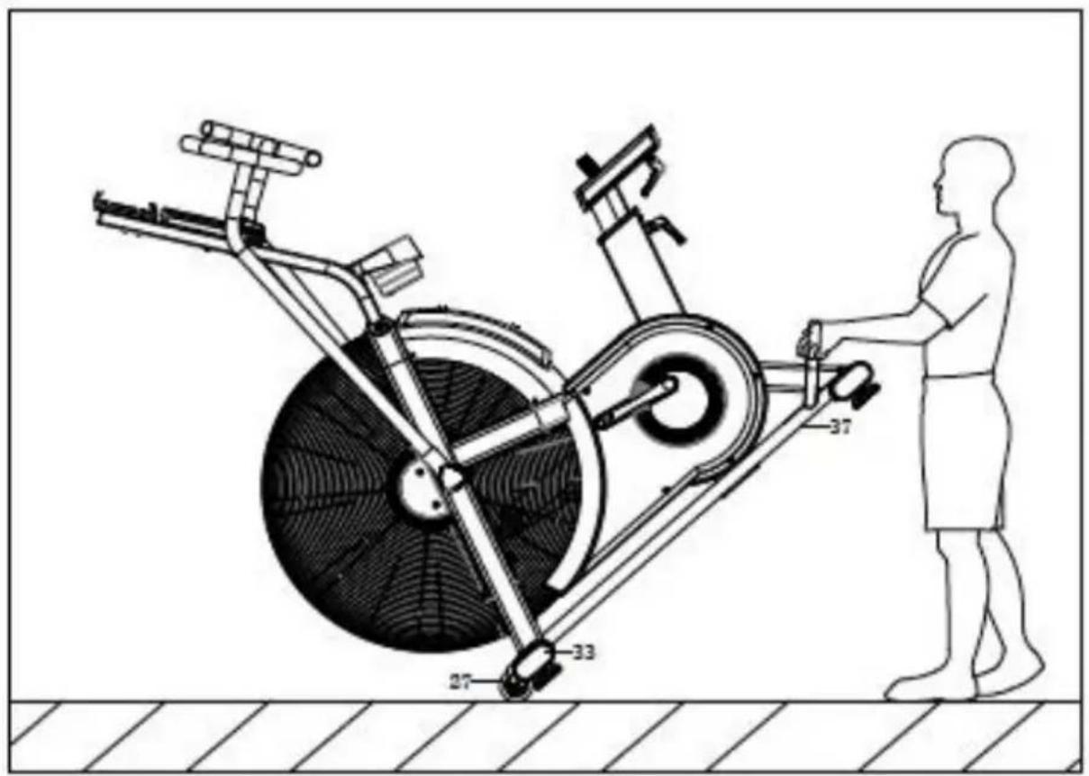
FIG 9:
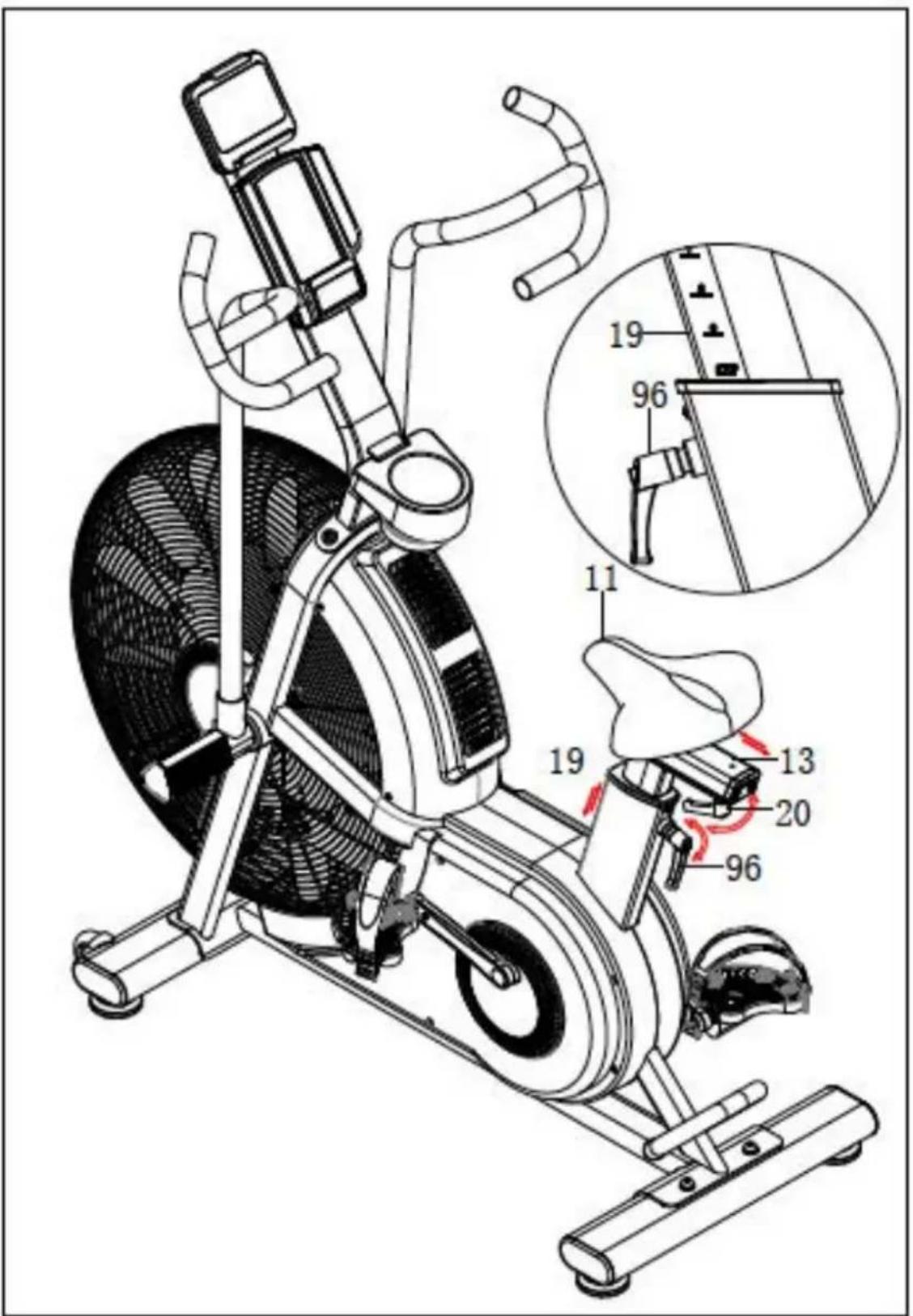
FIG 10:
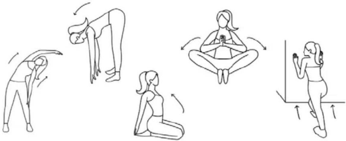
natural_image
Illustration of five sequential yoga or stretching exercises in different poses, showing forward bend, backbend, seated posture, and leg extension (no text or symbols)FIG 11:
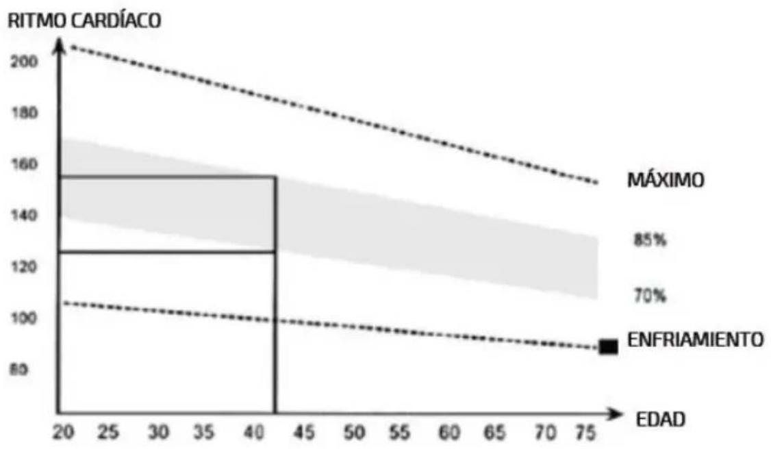
line
| EDAD | RITMO CARDÍACO | | ---- | -------------- | | 20 | 200 | | 40 | 160 | | 75 | 100 |www.cecotec.es
Cecotec Innovaciones S.L. Av. Reyes Católicos, 60 46910, Alfafar, Valencia (Spain)