PMFW 310 I6 - Multifunction tool PARKSIDE - Free user manual and instructions
Find the device manual for free PMFW 310 I6 PARKSIDE in PDF.

User questions about PMFW 310 I6 PARKSIDE
0 question about this device. Answer the ones you know or ask your own.
Ask a new question about this device
Download the instructions for your Multifunction tool in PDF format for free! Find your manual PMFW 310 I6 - PARKSIDE and take your electronic device back in hand. On this page are published all the documents necessary for the use of your device. PMFW 310 I6 by PARKSIDE.
USER MANUAL PMFW 310 I6 PARKSIDE
text_image
QR code image with a central logo, likely linking to a digital resource or website.PDF ONLINE
parkside-diy.com

natural_image
Black Parkside electric tool with visible wiring and handle (no text or symbols on body)MULTIFUNKTIONSWERKZEUG / MULTI-TOOL / OUTIL MULTIFONCTION PMFW 310 I6
DE AT BE CH
MULTIFUNKTIONSWERKZEUG
Bedienungsanleitung
Translation of the original instructions
FR BE
OUTIL MULTIFONCTION
natural_image
Simple line drawing of a 3D pipe elbow joint with a numbered label (9) pointing to the edge (no text or symbols on the diagram itself)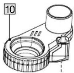
text_image
10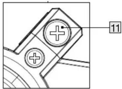
text_image
11B
text_image
C 9 10 11 9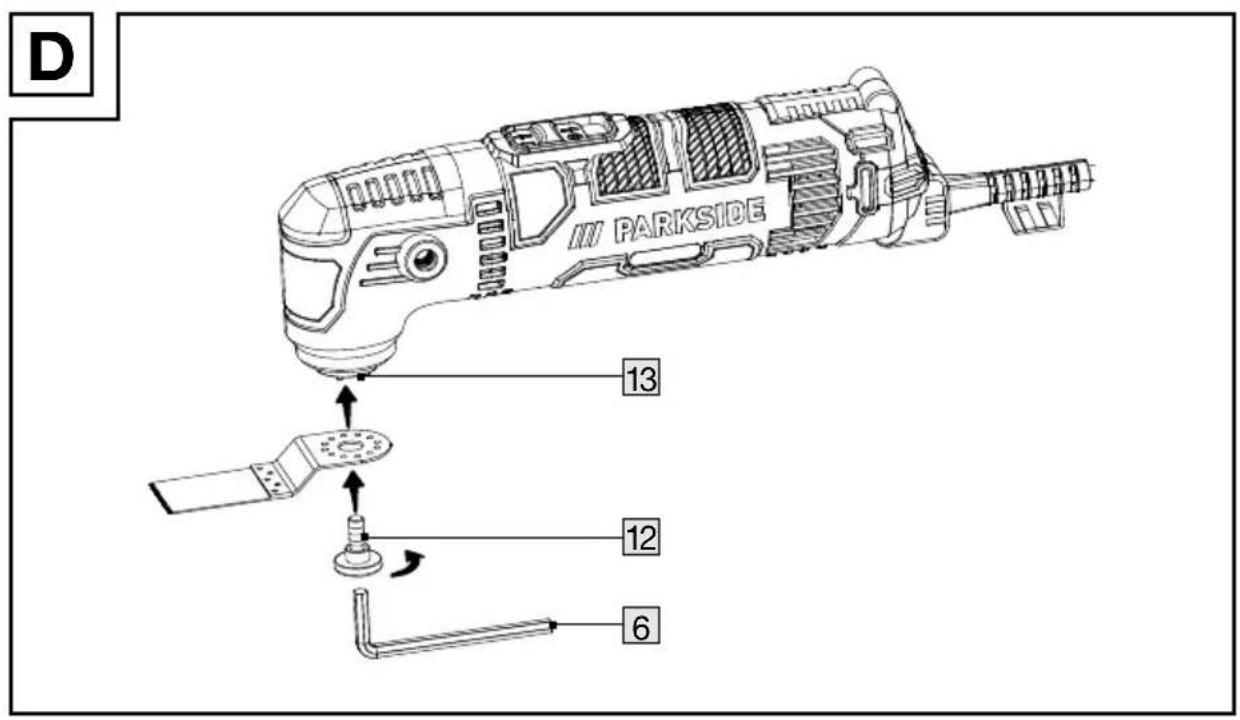
text_image
D PARKSIDE 13 12 6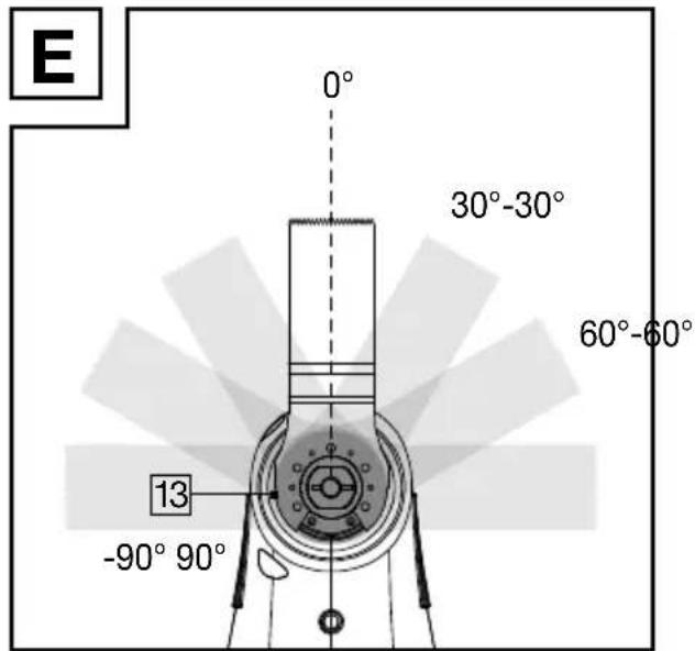
text_image
E 0° 30°-30° 60°-60° 13 -90° 90°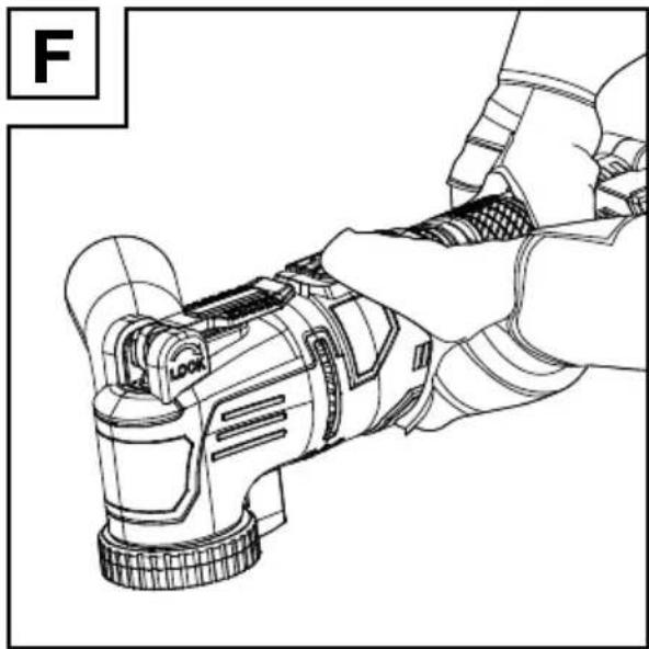
natural_image
Line drawing of a hand using a handheld device to adjust or install a component (no text or symbols visible)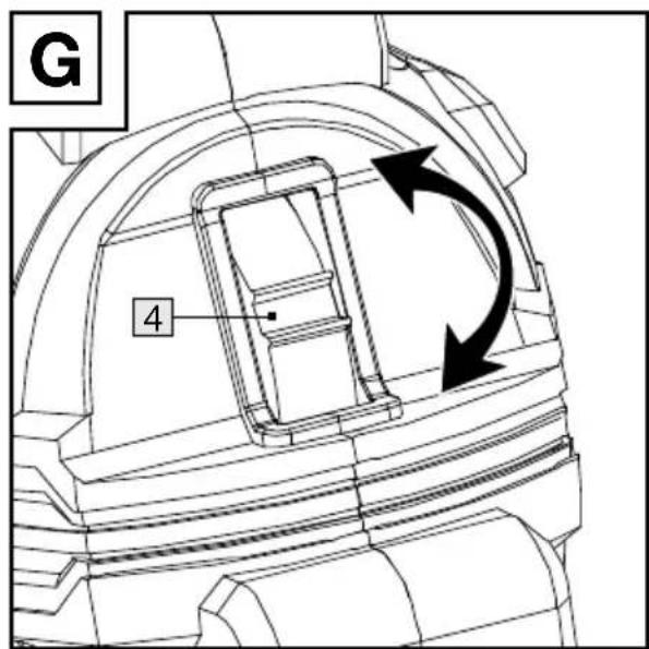
text_image
G 4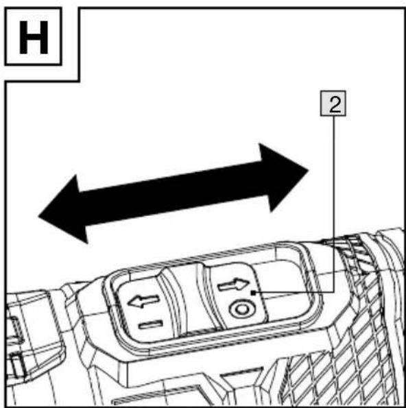
text_image
H 2natural_image
Technical line drawing of a mechanical component with an arrow pointing to it, no text or symbols present.Intended use.... Page 25
Scope of delivery Page 25
Parts list Page 25
Technical data.... Page 26
General safety instructions.... Page 27
General power tool safety warnings.... Page 27
Sander safety warnings ...... Page 29
Vibration and noise reduction.... Page 29
Behaviour in emergency situations.... Page 29
Residual risks ...... Page 29
First use Page 30
Accessories Page 30
Connecting/removing the dust extractor . . . . . . . . . . . . . . . . . . . . . . . . . . . . . . . . . . . . . . . . . . . . . . . . . . . . . . . . . . . . . . . . . . . . . . . . . . . 31
Installing the handle.... Page 31
Selecting an accessory tool....Page 31
Attaching/removing the accessory tool .... Page 32
Setting the oscillation speed ...... Page 33
Switching on and off.... Page 33
Trial run.... Page 33
Working instructions ...... Page 33
Cleaning and maintenance Page 34
Cleaning Page 34
Maintenance.... Page 34
Repair Page 34
Storage Page 34
Transportation.... Page 35
Disposal Page 35
Warranty.... Page 35
Warranty claim procedure.... Page 36
Service Page 36
EU declaration of conformity.... Page 37
| List of pictograms usedThe following warnings are used in this user manual, on the packaging, rating label and product labels : | |||
 | This symbol means that the operating instructions must be observed when using the product. |  | Switch off the product and disconnect it from the mains before replacing arrachments, cleaning and when not in use. |
 | This mandatory sign indicates to wear suitable protective gloves!Follow the instructions of this warning to avoid hand injuries caused by objects or contact with hot or chemical materials. |  | Lock |
 | Unlock | ||
| [3HH0] | Voltage | ||
 | Wear eye protection. |  | CE mark indicates conformity with relevant EU directives applicable for this product. |
 | Wear ear protection. | ||
 | Wear dust mask. |  | Symbol for a Protection Class II (double insulated) product |
| ~ | Alternating current/voltage | [9H67] | Safety information Instructions for use |
MULTI-TOOL
● Introduction
We congratulate you on the purchase of your new product. You have chosen a high quality product. The instructions for use are part of the product. They contain important information concerning safety, use and disposal. Before using the product, please familiarise yourself with all of the safety information and instructions for use. Only use the product as described and for the specified applications. If you pass the product on to anyone else, please ensure that you also pass on all the documentation with it.
Intended use
This MULTI-TOOL (hereinafter “product” or “power tool”) is designed for sawing, cutting, and sanding.
The product should preferably be used for the following materials: Wood, plastic, drywall materials, light and non-ferrous metals, fasteners (e.g. nails, screws), and wall tiles. The product is particularly suitable for flush applications and applications close to the edge.
The product can work on hard materials such as ceramics and concrete with suitable accessories.
Always use the correct accessory tools according to the intended use! Observe the technical requirements of this product (see “Technical data”) when purchasing and using accessory tools!
Any other use or modification of the product are considered improper use and can result in hazards such as death, life-threatening injuries and damage. The manufacturer is not liable for any damages caused by improper use. The product is not intended for commercial use or for any other use.
- Scope of delivery
WARNING!
The product and the packaging are not children's toys! Children must not play with plastic bags, sheets and small parts! There is a danger of choking and suffocation!
1 Multi-Tool
1 Handle
1 Dust extractor
1 Dust port
1 Sanding pad
18 Sand paper
2 Plunge saw blade
1 Segment saw blade
1 Scraper
1 Hex key
1 Carrying case
1 User manual
Parts list
Fig. A
| 1 | Ventilation slot (inlet) |
| 2 | On/Off switch |
| 3 | Main handle |
| 4 | Speed control dial |
| 5 | Power cord with power plug |
| 6 | Hex key |
| 7 | Handle |
| 8 | Connector |
| 9 | Dust port |
| 10 | Dust extractor |
| 11 | Connection screw |
| 12 | Locking screw |
Fig. B
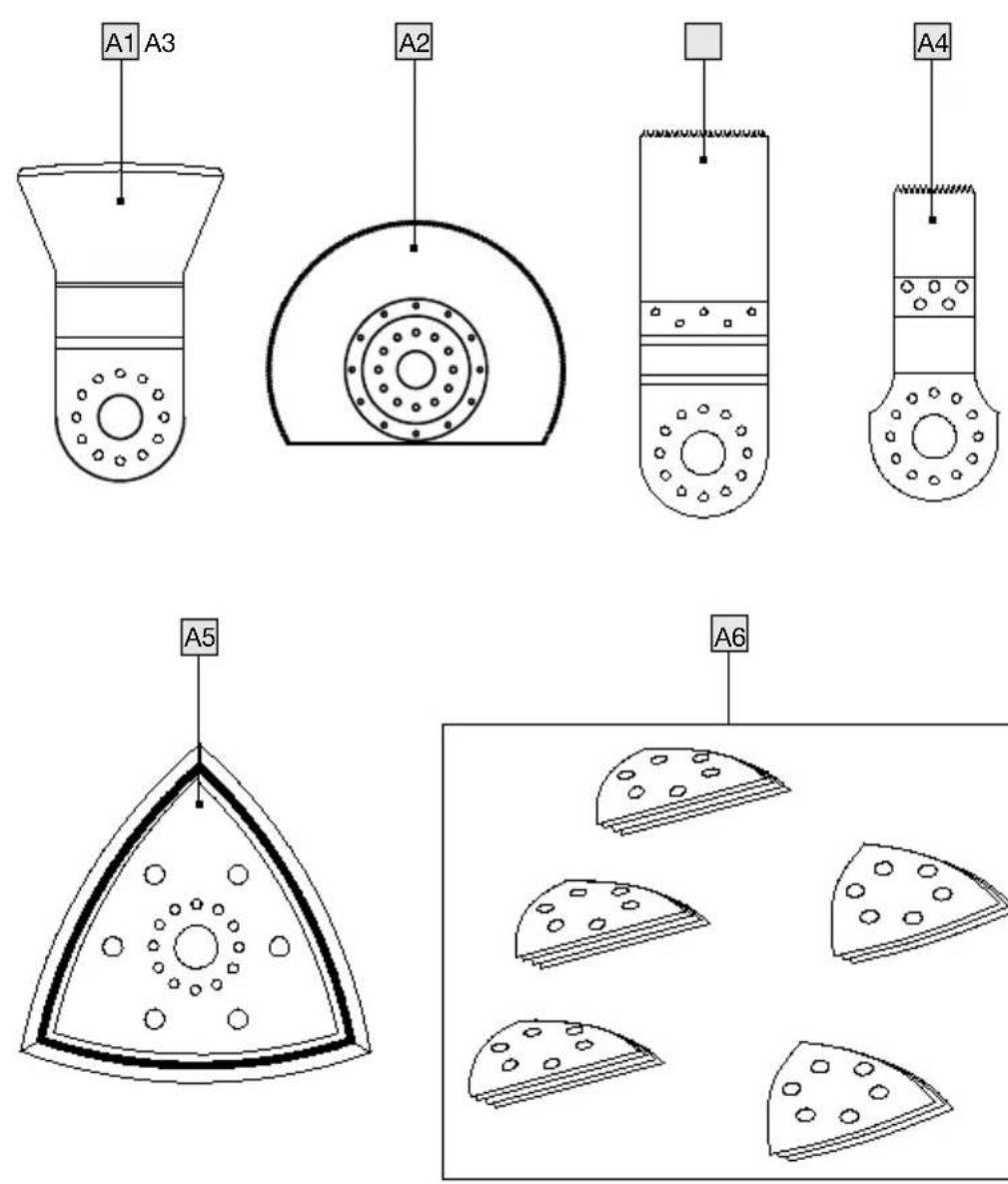
A1 Scraper Z52 A1
A2 Segment saw blade Z85 C3, HCS
A3 Plunge saw blade 32mm, Z32 C3, HCS
A4 Plunge saw blade 20mm, Z20 C3, HCS/HSS
A5 Sanding pad
A6 Sand paper
Wood : 4 x #60; 4 x #120; 4 x #240, red color
Metal : 3 x #120; 3 x #240, black color
Fig. D
13 Accessory tool holder
- Technical data
Multi-Tool PMFW 310 I6
Model number: HG13577
Rated voltage: 230 V\~, 50 Hz
Rated power
consumption: 310 W
Motor speed: 15000-21000 min ^-1
Oscillation speed: 15000-21000 min ^-1
Oscillation angle: 3.0°
Protection class: Class II / ☐
Noise emission value
The measured values have been determined in accordance with
EN 62841. The A-rated noise level of the power tool is typically as follows:
Sanding function
Sound pressure level: L _pA 81.1 dB
Cutting function
Sound pressure level: L pA 88.8 dB
Uncertainty: K pA 3 dB
Sanding function
Sound power level: L WA 89.1 dB
Cutting function
Sound power level: L WA 96.8 dB
Uncertainty: K WA 3 dB
Vibration emission value
Vibration total values (triaxial vector sum) determined according to EN 62841:
Sanding:
Sanding function
Vibration emission value: a_h 5.188 m/s ^2
Cutting function
Vibration emission value: a_h 6.985 m/s ^2
Uncertainty: K 1.5 m/s ^4

WARNING!

Wear ear protection!
NOTE
The declared vibration total value and the declared noise emission value have been measured in accordance with a standard test method and may be used for comparing one tool with another.
The declared total vibration value and the declared noise emission value may also be used for a preliminary assessment of exposure.

WARNING!
The vibration and noise emissions during actual use of the power tool can differ from the declared values depending on the manner in which the tool is used, especially what kind of workpiece is processed. Try to minimise exposure to vibration and noise. Examples of measures to reduce vibration include wearing gloves when using the tool and limiting working time. All parts of the operating cycle must be taken into account (e.g. times when the power tool is switched off and when it is running idle in addition to the trigger time).

General safety instructions
● General power tool safety warnings

WARNING!
Read all safety warnings, instructions, illustrations and specifications provided with this power tool. Failure to follow all instructions listed below may result in electric shock, fire and/or serious injury.
Save all warnings and instructions for future reference.
The term “power tool” in the warnings refers to your mains-operated (corded) power tool or battery-operated (cordless) power tool.
Work area safety
1) Keep work area clean and well lit. Cluttered or dark areas invite accidents.
2) Do not operate power tools in explosive atmospheres, such as in the presence of flammable liquids, gases or dust. Power tools create sparks which may ignite the dust or fumes.
3) Keep children and bystanders away while operating a power tool. Distractions can cause you to lose control.
Electrical safety
1) Power tool plugs must match the outlet. Never modify the plug in any way. Do not use any adapter plugs with earthed (grounded) power tools. Unmodified plugs and matching outlets will reduce risk of electric shock.
2) Avoid body contact with earthed or grounded surfaces, such as pipes, radiators, ranges and refrigerators. There is an increased risk of electric shock if your body is earthed or grounded.
3) Do not expose power tools to rain or wet conditions. Water entering a power tool will increase the risk of electric shock.
4) Do not abuse the cord. Never use the cord for carrying, pulling or unplugging the power tool. Keep cord away from heat, oil, sharp edges or moving parts. Damaged or entangled cords increase the risk of electric shock.
5) When operating a power tool outdoors, use an extension cord suitable for outdoor use. Use of a cord suitable for outdoor use reduces the risk of electric shock.
6) If operating a power tool in a damp location is unavoidable, use a residual current device (RCD) protected supply. Use of an RCD reduces the risk of electric shock.
Personal safety
1) Stay alert, watch what you are doing and use common sense when operating a power tool. Do not use a power tool while you are tired or under the influence of drugs, alcohol or medication. A moment of inattention while operating power tools may result in serious personal injury.
2) Use personal protective equipment. Always wear eye protection. Protective equipment such as dust mask, non-skid safety shoes, hard hat, or hearing protection used for appropriate conditions will reduce personal injuries.
3) Prevent unintentional starting. Ensure the switch is in the off-position before connecting to power source and/or battery pack, picking up or carrying the tool. Carrying power tools with your finger on the switch or energising power tools that have the switch on invites accidents.
4) Remove any adjusting key or wrench before turning the power tool on. A wrench or a key left attached to a rotating part of the power tool may result in personal injury.
5) Do not overreach. Keep proper footing and balance at all times. This enables better control of the power tool in unexpected situations.
6) Dress properly. Do not wear loose clothing or jewellery. Keep your hair, clothing and gloves away from moving parts. Loose clothes, jewellery or long hair can be caught in moving parts.
7) If devices are provided for the connection of dust extraction and collection facilities, ensure these are connected and properly used. Use of dust collection can reduce dust-related hazards.
8) Do not let familiarity gained from frequent use of tools allow you to become complacent and ignore tool safety principles. A careless action can cause severe injury within a fraction of a second.
Power tool use and care
1) Do not force the power tool. Use the correct power tool for your application. The correct power tool will do the job better and safer at the rate for which it was designed.
2) Do not use the power tool if the switch does not turn it on and off. Any power tool that cannot be controlled with the switch is dangerous and must be repaired.
3) Disconnect the plug from the power source and / or the battery pack from the power tool before making any adjustments, changing accessories, or storing power tools. Such preventive safety measures reduce the risk of starting the power tool accidentally.
4) Store idle power tools out of the reach of children and do not allow persons unfamiliar with the power tool or these instructions to operate the power tool. Power tools are dangerous in the hands of untrained users.
5) Maintain power tools and accessories. Check for misalignment or binding of moving parts, breakage of parts and any other condition that may affect the power tool's operation. If damaged, have the power tool repaired before use. Many accidents are caused by poorly maintained power tools.
6) Keep cutting tools sharp and clean. Properly maintained cutting tools with sharp cutting edges are less likely to bind and are easier to control.
7) Use the power tool, accessories and tool bits etc. in accordance with these instructions, taking into account the working conditions and the work to be performed. Use of the power tool for operations different from those intended could result in a hazardous situation.
8) Keep handles and grasping surfaces dry, clean and free from oil and grease. Slippery handles and grasping surfaces do not allow for safe handling and control of the tool in unexpected situations.
Service
1) Have your power tool serviced by a qualified repair person using only identical replacement parts. This will ensure that the safety of the power tool is maintained.
● Sander safety warnings

WARNING!
Dust from materials such as lead paint, some types of wood, and metal can be harmful to your health.
Lead or lead-containing materials may not be processed.
Contact with or inhaling this type of dust can present a danger to the user or persons nearby.

WARNING!


Wear safety glasses and a dust mask!
● Vibration and noise reduction
To reduce the impact of noise and vibration emission, limit the time of operation, use low-vibration and low-noise operating modes as well as wear personal protective equipment.
Take the following points into account to minimise the vibration and noise exposure risks:
■ Only use the product as intended by its design and these instructions.
■ Ensure that the product is in good condition and well maintained.
- Use correct accessory tools for the product and ensure they are in good condition.
- Keep tight grip on the handles / grip surface.
- Maintain this product in accordance with these instructions and keep it well lubricated (where appropriate).
Plan your work schedule to spread any high vibration tool use across a longer period of time.
● Behaviour in emergency situations
Familiarise yourself with the use of this product by means of this user manual. Memorise the safety warnings and follow them to the letter. This will help to prevent risks and hazards.
■ Always be alert when using this product, so that you can recognise and handle risks early. Fast intervention can prevent serious injury and damage to property.
■ Switch the product off and disconnect it from the mains if there are malfunctions. Have the product checked by a qualified professional and repaired, if necessary, before you operate it again.
Residual risks
Even if you are operating this product in accordance with all the safety requirements, potential risks of injury and damage remain. The following dangers can arise in connection with the structure and design of this product:
■ Health defects resulting from vibration emission if the product is being used over long periods of time or not adequately managed and properly maintained.
Injuries and damage to property due to broken accessory tools or the sudden impact of hidden objects during use.
■ Danger of injury and property damage caused by flying objects.
NOTE
This product produces an electromagnetic field during operation! This field may under some circumstances interfere with active or passive medical implants! To reduce the risk of serious or fatal injury, we recommend persons with medical implants to consult their doctor and the medical implant manufacturer before operating this product!
- First use
Accessories
To operate this product safely and correctly, the following accessories, i.e. tools and accessory tools, are necessary:
■ Suitable accessory tools
■ Suitable personal protective equipment
Accessories and accessory tools are available through your authorised dealer. When buying always consider the technical requirements of this product (see “Technical data”).
If you are not certain, ask a qualified specialist and get advice from your trusted dealer.
NOTE
This user manual contains information and suggestions for several accessory tools and their uses. The accessory tools depicted are not included in the shipment (see “Scope of delivery”), but are meant to indicate additional possibilities for using this product.
WARNING!
Do not use accessories not recommended by Parkside. This may result in electric shock or fire.
WARNING!

Switch off the product and disconnect it from the mains before replacing arrachments, cleaning and when not in use.
- Connecting/removing the dust extractor
WARNING! FIRE HAZARD!
Using power tools with a dust extraction element which can be connected to a vacuum cleaner poses a fire hazard! Unfavourable conditions, e.g. sparking, sanding metal or metal pieces in wood, wood dust inside the vacuum bag can ignite. This can particularly occur if the wood dust is mixed with paint particles or other chemicals and the ground product is hot after long work periods. Therefore avoid the sanding material and the product overheating. Always empty the vacuum bag in the vacuum cleaner before taking breaks.
Always use a dust extractor.
▶ Ensure the work area is well ventilated.
Observe your country's applicable rules for the materials you are working on.
NOTE
Connecting or removing the dust extractor 10: Use a cross-head hand screwdriver (not included).
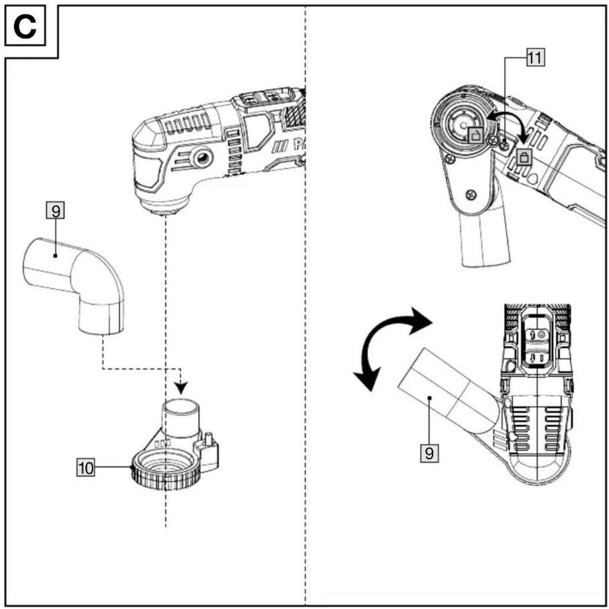
(Fig. C) Connecting the dust extractor
Place the dust extrac ^10 at the bottom side of the product.
- Align the connection screen with the hole in the connector 8.
- Hold the main hand 3. Turn the product by 90^ .
Use a cross-head screwdriver (not included) to turn the connection screw 11 in a clockwise direction until fully tightened.
- Slightly press the dust p9 onto the dust extractor 10 until the dust extractor is firmly connected to the dust port.
- You can orient the dust p9 in different directions to suit different working environments.
Removing the dust extractor
■ Turn the connection scr11 in an anti-clockwise direction until completely loose.
■ Remove the dust extrac ^10 from the product.
Installing the handle
- Screw the handle 7 on either side of the machine to increase control.
- Selecting an accessory tool
NOTE
The following accessory tools constitute the most common types.
If desired, consult specialist retailers about further accessory tools.
Plunge cut saw blade (Fig. B, A3, A4)
Materials: ■ Wood
Plastic
Plaster
other soft materials
Use: ■ Cut-off cuts
Plunge cuts
■ Sawing close to the edge, including in hard-to-reach areas
Example: ■ Cutting notches in light construction walls
Segment saw blade (Fig. B, A2)
Materials: ■ Wood
Plastic
■ Other soft materials
Use: ■ Cut-off cuts
■ Sawing close to the edge
Examples: ■ Cutting notches
■ Cutting off strip, small section tube or profile
Scraper (Fig. B, A1)
Materials: ■ Mortar/cement residue
- Tile/carpet adhesive
■ Paint/silicone residue
Use: ■ Removing material residue
Example: ■ Removing carpet adhesive residue on floors
Sanding paper (Fig. B, A6)
Materials: ■ Wood and metal
Wood*
Metal*
* depending on sanding sheet
Use: ■ Sanding along edges
■ Sanding along hard-to-reach areas
- Attaching/removing the accessory tool
(Fig. D)
CAUTION! RISK OF INJURY!

Accessory tools can be sharp and may become hot during use. Always wear protective gloves when handling accessory tools!
WARNING!

Switch off the product and disconnect it from the mains before replacing arrachments, cleaning and when not in use.
CAUTION! RISK OF INJURY!
Keep your hands away from the accessory tool when the product is in operation.
NOTE
To use the dust extrac ^10 ; you will need to connect it before attaching the accessory tool (see "Connecting/removing the dust extractor").
Inserting the accessory tool
(Fig. D)
- Unscrew the locking screw 12.
- Inserting open end of accessory tools into the accessory tool holder 13.
NOTE
The accessory tools can be held by the magnet on the tool holder before tightening.
You can attach the accessory tools into the accessory tool holder 13 in any lock-in position (Fig. E).
Tightening the accessory tool
(Fig. D)
■ Tighten the locking scr12 by hex key 6 in clockwise.
Removing the accessory tool
(Fig. D)
- Unscrew the locking screw 12.
- Pull the accessory tool out of the accessory tool holder 13.
- After removing the accessory tool: tighten the locking screw back.
- Setting the oscillation spee
■ Use the speed control dial 4 to set the oscillation speed (Fig. G).
Setting 1: Low oscillation speed
Setting 6: High oscillation speed
NOTE
The oscillation speed required varies by material and working conditions and can be determined with tests.
The oscillation speed can also be changed during operation.
- Switching on and off

CAUTION! RISK OF INJURY!

Always wear protective gloves when handling or working with the product.

CAUTION! RISK OF INJURY!
Always hold the product with both hands while working (Fig. F).

CAUTION! RISK OF INJURY!
Keep your hands away from the accessory tool when the product is in operation.

CAUTION! HEALTH RISK!
▶ Never work on materials containing asbestos. Asbestos is considered carcinogenic.
(Fig. H)
■ Switching on: Slide the on/off switch 2 forward (ON).
■ Switching off: Slide the on/off switch 2 back (OFF).
Trial run
NOTE
Always carry out a no-load trial run before starting work and after every accessory tool replacement. The trial run is to make sure the accessory tools are correctly locked in place and will not become loose during operation.
● Working instructions
Working principle:
The oscillating motor allows the accessory tool to oscillate back and forth 15000 to 21000 times per minute. This allows for precision in the tightest of spaces.
Sawing/cutting:
■ Only use undamaged saw blades free from defects. Bent, dull or otherwise saw blades can break.
- Observe the law and the recommendations of the material manufacturers when cutting light construction materials.
■ Only soft materials such as softwood, gypsum plasterboard etc. may be processed using plunge cutting!
Sanding:
natural_image
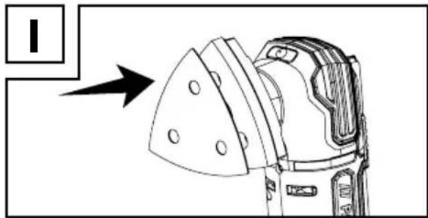
Technical line drawing of a mechanical component with an arrow pointing to it, no text or symbols present.- Attaching sanding paper: Press the sanding paper A6 onto the sanding pad A5 (Fig. I).
■ Removing sanding paper: Peel the sanding paper A6 from the rim of the sanding pad A5 and remove it.
■ Apply even pressure to extend the life of the sanding sheets.
● Cleaning and maintenance

WARNING!

Switch off the product and disconnect it from the mains before replacing arrachments, cleaning and when not in use.

Cleaning
■ Never allow fluids to get into the product.
The product must always be kept clean, dry and free from oil or grease. Remove debris from it after each use and before storage.
■ Regular and proper cleaning will help ensure safe use and prolong the life of the product.
- Clean the product with a dry cloth. Use a soft brush for areas that are hard to reach.
In particular clean the ventilation slot 1 after every use with a cloth and soft brush.
■ The vents must always be clear.
NOTE
Do not use chemical, alkaline, abrasive or other aggressive detergents or disinfectants to clean this product as they might be harmful to its surfaces.
Maintenance
The product is maintenance-free.
Before and after each use, check the product and accessories (e.g. accessory tools) for wear and damage. If required, exchange them for new ones as described in this user manual. Observe the technical requirements (see “Technical data”).
- Check covers and safety devices for damages and correct installation. Replace as necessary.
Repair

WARNING! Risk of injury!
If the mains cc5 is damaged. it must be replaced by the manufacturer, its service agent or similarly qualified persons in order to avoid a hazard.
This product does not contain any parts that can be repaired by the user. Contact an authorised service centre or a similarly qualified person to have it checked and repaired.
Storage
■ Switch the product off.
- Clean the product as described above.
■ Store the product and its accessories in a dark, dry, frost-free, well-ventilated place.
■ Always store the product in a place that is inaccessible to children. The ideal long term storage (longer than 3 months) temperature is between +10 and +30 °C and relative humidity not above 60%.
■ Store the product in its carrying case.
Transportation
■ Switch the product off.
■ Transport the product in its carrying case.
■ Protect the product from any heavy impact or strong vibrations which may occur during transportation in vehicles.
- Secure the product to prevent it from slipping or falling over.
- Disposal
The packaging is made of environmentally friendly materials, which may be disposed of through your local recycling facilities.

Observe the marking of the packaging materials for waste separation, which are marked with abbreviations (a) and numbers (b) with following meaning: 1–7: plastics/20–22: paper and fibreboard/80–98: composite materials.
Product:
The product incl. accessories, manual and packaging materials are recyclable and are subject to extended producer responsibility.
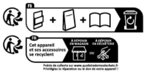
Dispose them separately, following the illustrated Info-tri (sorting information), for better waste treatment. The Triman logo is valid in France only.

Contact your local refuse disposal authority for more details of how to dispose of your wornout product.
To help protect the environment, please dispose of the product properly when it has reached the end of its useful life and not in the household waste. Information on collection points and their opening hours can be obtained from your local authority.
Faulty or used batteries/rechargeable batteries must be recycled. Return the batteries/rechargeable batteries and the product to the available collection points.
● Warranty
The product has been manufactured to strict quality guidelines and meticulously examined before delivery. In the event of material or manufacturing defects you have legal rights against the retailer of this product. Your legal rights are not limited in any way by our warranty detailed below.
The warranty for this product is 3 years from the date of purchase. The warranty period begins on the date of purchase. Keep the original sales receipt in a safe location as this document is required as proof of purchase.
Any damage or defects already present at the time of purchase must be reported without delay after unpacking the product.
Should the product show any fault in materials or manufacture within 3 years from the date of purchase, we will repair or replace it – at our choice – free of charge to you. The warranty period is not extended as a result of a claim being granted. This also applies to replaced and repaired parts.
This warranty becomes void if the product has been damaged, or used or maintained improperly.
The warranty covers material or manufacturing defects. This warranty does not cover product parts subject to normal wear and tear, thus considered consumables (e.g. batteries, tubes, cartridges), nor damage to fragile parts, e.g. switches or glass parts.
● Warranty claim procedure
So that your request can be processed quickly, please observe the following instructions:
For all inquiries, please have the receipt and item number (IAN 500083_2504) ready as proof of purchase.
The article number can be taken from the identification label on the product, engraving on the product, the front cover of your manual (at the bottom left), or the sticker on the back or bottom of the product.
If malfunctions or other defects arise, first contact the service department indicated below by phone or email.
You can then send a product recorded as defective to the communicated service address postage-free, making sure to enclose proof of purchase (receipt) and information on the details of the defect and when it occurred.
You can download and view this and numerous other manuals at parkside-diy.com. This QR code takes you directly to parkside-diy.com. Choose your country and use the search screen to search for the operating instructions. Entering the item number (IAN) 500083_2504 takes you to the operating instructions for your item.

text_image
QR code image containing encoded data, with a central logo or watermarkPDF ONLINE parkside-diy.com
Service
GB Service Great Britain
Tel.:08000518970
Contact form on parkside-diy.com
IAN 500083_2504
IE Service Ireland
Tel.:1800851251
Contact form on parkside-diy.com
IAN 500083_2504
EU declaration of conformity
EU DECLARATION OF CONFORMITY (No 500083\_2501)
IAN:
500083_2501
Product identification:
"PARKSIDE" Multi-purpose tool
Model Number:
HG13577
The object of the declaration described above is in conformity with the relevant Union harmonisation legislation:
| Directive 2006/42/EC |
| Directive 2014/30/EU |
| Directive 2011/65/EU and all related amendments |
References to the relevant harmonised standards used or references to the other technical specifications in relation to which conformity is declared:
| N° / Parts |
| Directive 2006/42/EC |
| EN 62841-1:2015/A11:2022 |
| EN 62841-2-4:2014/AC:2015 |
| EN ISO 12100:2010 |
| Directive 2014/30/EU |
| EN IEC 55014-1:2021 |
| EN IEC 55014-2:2021 |
| EN IEC 61000-3-2:2019/A1:2024 |
| EN 61000-3-3:2013/A2:2021 |
The object of the declaration described above is in conformity with Directi ve 2011/65/EU of the European Parliament and of the Council of 8 June 2011 on the restriction of the use of certain hazardous substances in electrical and electronic equipment:
| N° / Parts |
| EN IEC 63000:2018 |
Keeper of the technical documentation: OWIM GmbH & Co.KG
Signed for and on behalf of:
This declaration of conformity is issued under the sole responsibility of the manufacturer.
Translation of the original declaration of conformity
Neckarsulm 01.08.2025
Place
Date

text_image
ppa. Guesel ppa. Stefan Haensel ppa. Jens BuchheimAuthorised Signatory
Authorised Signatory
PRUDENCE ! RISUE POUR LA SANTÉ !
natural_image
Technical line drawing of a mechanical component with an arrow pointing to it, no text or symbols present.WAARSCHUWING! BRANDGEVAAR!
natural_image
Technical line drawing of a mechanical device with an arrow pointing to a component (no text or symbols present)natural_image
Technical line drawing of a mechanical device with a directional arrow pointing to it (no text or symbols present)natural_image
Technical line drawing of a mechanical device with a directional arrow pointing to it (no text or symbols present)text_image
QR code image with a central logo, likely linking to a digital resource or website.PDF ONLINE parkside-diy.com
Servis
natural_image
Technical line drawing of a mechanical component with an arrow pointing to a section (no text or symbols present)motor: 15000 = 21000 min
Velocidad de
oscilación:
Ángulo de
oscilación: 3,0°
Clase de