PEKSG 85 F4 - Electric sharpener PARKSIDE - Free user manual and instructions
Find the device manual for free PEKSG 85 F4 PARKSIDE in PDF.

User questions about PEKSG 85 F4 PARKSIDE
0 question about this device. Answer the ones you know or ask your own.
Ask a new question about this device
Download the instructions for your Electric sharpener in PDF format for free! Find your manual PEKSG 85 F4 - PARKSIDE and take your electronic device back in hand. On this page are published all the documents necessary for the use of your device. PEKSG 85 F4 by PARKSIDE.
USER MANUAL PEKSG 85 F4 PARKSIDE
text_image
QR code image with a central logo, likely linking to a digital resource or website.PDF ONLINE
parkside-diy.com

natural_image
Mechanical device with chain link and lever mechanism (no visible text or symbols)ELEKTRO-KETTENSCHÄRFGERÄT/ELECTRIC CHAIN SHARPENER/AFFÜTEUSE DE CHAÎNES PEKSG 85 F4
DE AT BE CH
ELEKTRO-KETTENSCHÄRFGERÄT
Operation and safety notes
Translation of the original instructions
FR BE
AFFÛTEUSE DE CHAÎNES
GB/IE Operation and safety notes Page 24
text_image
Technical diagram of a microscope with numbered parts and labeled connectorsB
text_image
B 16 15 2 4 11 8 9C
text_image
Technical diagram of a mechanical device with numbered parts labeled 20, 21, 22, 23, and 8.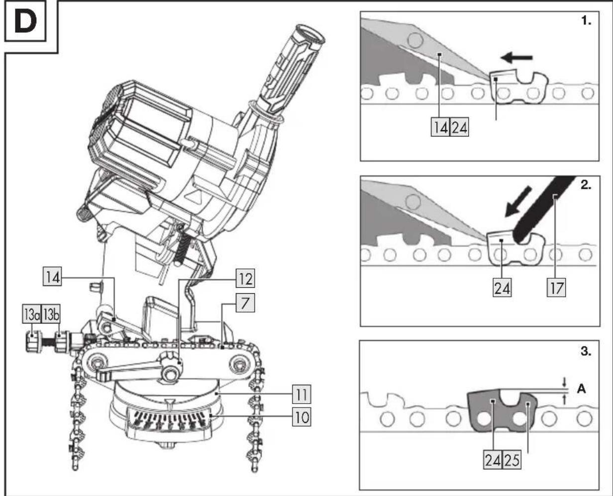
Directive 2006/42/EG
Directive 2014/30/EG
List of pictograms used ...... Page 25
Introduction Page 26
Intended use.... Page 26
Scope of delivery ...... Page 26
Description of parts.... Page 26
Technical data. Page 27
Safety instructions ...... Page 28
General power tool safety warnings ...... Page 28
Additional safety instructions.... Page 30
Assembly.... Page 31
Assembling the product....Page 31
Attaching the product to the worktop. Page 32
Operation.... Page 32
Switching on/off Page 33
Sharpening the saw chain.... Page 33
Cleaning and maintenance Page 35
Cleaning Page 35
Maintenance Page 35
Transportation.... Page 36
Storage Page 36
Disposal Page 36
Warranty.... Page 37
Warranty claim procedure.... Page 37
Service Page 38
EU declaration of conformity.... Page 39
| List of pictograms used | |||
  | This symbol means that the operating instructions must be observed when using the product. |  | Wear hearing protection! |
 | DANGER! - Designating a hazard with high risk, which will result in death or severe injury if not avoided (e.g. risk of suffocation) |  | Wear dust protection! |
 | WARNING! - Designating a hazard with moderate risk, which can result in death or severe injury if not avoided (e.g. risk of electric shock) |  | Wear eye protection! |
 | CAUTION! - Designating a hazard with low risk, which could result in minor or moderate injury if not avoided (e.g. risk of scalding) |  | Wear protective gloves! |
 | NOTICE! - Warns of possible damage to property/the product if not avoided (e.g. risk of short circuit) |  | Wear a protective apron! |
 | Injury hazard caused by rotating tool! Keep hands away. |  | Protection class II(Double insulation) |
 | Danger of electric shock! Remove the mains plug from the mains socket before carrying out maintenance and repair work. |  | CAUTION! Do not stare into the bright light! |
 | Grinding disc dimensions | ||
 | Do not expose the product to rain. |  | Never use faulty grinding discs |
 | CE mark indicates conformity with relevant EU directives applicable for this product. | Safety informationInstructions for use | |
ELECTRIC CHAIN SHARPENER
Introduction
We congratulate you on the purchase of your new product. You have chosen a high quality product. The instructions for use are part of the product. They contain important information concerning safety, use and disposal. Before using the product, please familiarise yourself with all of the safety information and instructions for use. Only use the product as described and for the specified applications. If you pass the product on to anyone else, please ensure that you also pass on all the documentation with it.
Intended use
The product is suitable for sharpening all common types of saw chains. The product is not intended for any other type of application (e.g. grinding with a coolant solution, grinding other workpieces or hazardous materials such as asbestos).
The product is intended to be used by do-it-yourselfers.
The product was not designed for heavy commercial use. Commercial use invalidates the guarantee.
The product is intended for use by adults. Children under the age of 16 may not use the product, except under supervision.
The manufacturer is not liable for damage caused by improper use or incorrect operation.
- Scope of delivery
WARNING!
The product and the packaging are not children's toys! Children must not play with plastic bags, sheets and small parts! There is a danger of choking and suffocation!
1 Electric chain sharpener
1 Handgrip
1 Chain tensioning unit with retaining screw
1 Adjusting screw
1 Adjusting nut
2 Screws
2 Nuts
2 Washers
1 User manual
• Description of parts
1 On/off switch
2 Grinding head
3 Grinding disc cover
4 Handgrip
5 Mounting screws (grinding disc cover)
6aAdjusting screw (depth stop)
6bAdjusting nut (depth stop)
7 Chain guide rail
8 Grinding base
9 Adjusting screw (chain tensioning unit)
10Scale for sharpening angle (+35° to -35°)
11 Chain tensioning unit with rotary plate
12 Tension lever (fixing chain)
13a Adjusting screw (chain feed) (pre-assembled)
13bAdjusting nut (chain feed) (pre-assembled)
14Stop
15 Cord holder
16Mains cord with mains plug
17 Grinding disc
17a Grinding disc nut
18Viewing guard
19 Ventilation holes
20Screws
21 Nuts
22 Washers
23Stop notch
24Cutting tooth
25Depth gauge nib
- Technical data
| Electric chain sharpener PEKSG | 85 F4 |
| Weight (incl. accessories): | 2.1 kg |
| Nominal input voltage: 230–240 | V~, 50 Hz |
| Idle power consumption P_0 : | 23 W (S1) |
| Maximum Power consumption P: | 85 W (S2 15 min) * |
| Protection class: | II / ☐ |
| Protection type: | IPX0 |
| Rated idle speed n_2 : 5,000 min | -1 |
| Adjustment angle: 35° left/right |
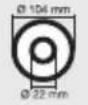
| Grinding disc PA 104 WA 100 | |
| Outer diameter: 104 mm | |
| Bore hole: 22 mm | |
| Thickness: 3.2 mm | |
| Idling speed n_0 : | max. 7,350 min ^-1 |
| Rotational speed: | max. 40 m/s** |
NOTE
Suitable for all common saw chains with link size 3/8" (low profile), for link sizes 0.325" and 1/4" , which can be processed with 1/8" (3.2 mm) strong grinding wheels (note the chain manufacturer's instructions).
Information on reordering grinding discs: see “Replacement parts/Accessories”
Noise emission value
The measured values have been determined in accordance with EN 62841. The A-rated noise level of the product is typically as follows:
| Sound pressure level L_pA : | 60.3 dB |
| Uncertainty K_pA : | 3.0 dB |
| Sound power level L_WA : | 73.3 dB |
| Uncertainty K_WA : | 3.0 dB |
Total vibration value
Total vibration values (triaxial vector sum) determined in accordance with EN 62841:
| Vibration a_h : | 2.5 m/s ^2 |
| Uncertainty K: | 1.5 m/s ^2 |
WARNING!

Wear hearing protection!

WARNING!
The vibration and noise emissions during actual use of the product can differ from the declared values depending on the manner in which the tool is used, especially what kind of workpiece is processed. Try to minimise exposure to vibration and noise. Examples of measures to reduce vibration include wearing gloves when using the tool and limiting working time. All parts of the operating cycle must be taken into account (e.g. times when the product is switched off and when it is running idle in addition to the trigger time).
NOTE
The declared vibration total value and the declared noise emission value have been measured in accordance with a standard test method and may be used for comparing one tool with another.
The declared total vibration value and the declared noise emission value may also be used for a preliminary assessment of exposure.

Safety instructions
● General power tool safety warnings

WARNING!
Read all safety warnings, instructions, illustrations and specifications provided with this power tool. Failure to follow the warnings and instructions may result in electric shock, fire and/or serious injury.
Save all warnings and instructions for future reference.
The term “power tool” in the warnings refers to your mains-operated (corded) power tool or battery-operated (cordless) power tool.
Work area safety
1) Keep work area clean and well lit. Cluttered or dark areas invite accidents.
2) Do not operate power tools in explosive atmospheres, such as in the presence of flammable liquids, gases or dust. Power tools create sparks which may ignite the dust or fumes.
3) Keep children and bystanders away while operating a power tool. Distractions can cause you to lose control.
Electrical safety
1) Power tool plugs must match the outlet. Never modify the plug in any way. Do not use any adapter plugs with earthed (grounded) power tools. Unmodified plugs and matching outlets will reduce risk of electric shock.
2) Avoid body contact with earthed or grounded surfaces, such as pipes, radiators, ranges and refrigerators. There is an increased risk of electric shock if your body is earthed or grounded.
3) Do not expose power tools to rain or wet conditions. Water entering a power tool will increase the risk of electric shock.
4) Do not abuse the cord. Never use the cord for carrying, pulling or unplugging the power tool. Keep cord away from heat, oil, sharp edges or moving parts. Damaged or entangled cords increase the risk of electric shock.
5) When operating a power tool outdoors, use an extension cord suitable for outdoor use. Use of a cord suitable for outdoor use reduces the risk of electric shock.
6) If operating a power tool in a damp location is unavoidable, use a residual current device (RCD) protected supply. Use of an RCD reduces the risk of electric shock.
Personal safety
1) Stay alert, watch what you are doing and use common sense when operating a power tool. Do not use a power tool while you are tired or under the influence of drugs, alcohol or medication. A moment of inattention while operating power tools may result in serious personal injury.
2) Use personal protective equipment. Always wear eye protection. Protective equipment such as dust mask, non-skid safety shoes, hard hat, or hearing protection used for appropriate conditions will reduce personal injuries.
3) Prevent unintentional starting. Ensure the switch is in the off-position before connecting to power source and/or battery pack, picking up or carrying the tool. Carrying power tools with your finger on the switch or energising power tools that have the switch on invites accidents.
4) Remove any adjusting key or wrench before turning the power tool on. A wrench or a key left attached to a rotating part of the power tool may result in personal injury.
5) Do not overreach. Keep proper footing and balance at all times. This enables better control
of the power tool in unexpected situations.
6) Dress properly. Do not wear loose clothing or jewellery. Keep your hair, clothing and gloves away from moving parts. Loose clothes, jewellery or long hair can be caught in moving parts.
7) If devices are provided for the connection of dust extraction and collection facilities, ensure these are connected and properly used. Use of dust collection can reduce dust-related hazards.
8) Do not let familiarity gained from frequent use of tools allow you to become complacent and ignore tool safety principles. A careless action can cause severe injury within a fraction of a second.
Power tool use and care
1) Do not force the power tool. Use the correct power tool for your application. The correct power tool will do the job better and safer at the rate for which it was designed.
2) Do not use the power tool if the switch does not turn it on and off. Any power tool that cannot be controlled with the switch is dangerous and must be repaired.
3) Disconnect the plug from the power source and/or the battery pack, if detachable, from the power tool before making any adjustments, changing accessories, or storing power tools. Such preventive safety measures reduce the risk of starting the power tool accidentally.
4) Store idle power tools out of the reach of children and do not allow persons unfamiliar with the power tool or these instructions to operate the power tool. Power
tools are dangerous in the hands of untrained users.
5) Maintain power tools and accessories. Check for misalignment or binding of moving parts, breakage of parts and any other condition that may affect the power tool's operation. If damaged, have the power tool repaired before use. Many accidents are caused by poorly maintained power tools.
6) Keep cutting tools sharp and clean. Properly maintained cutting tools with sharp cutting edges are less likely to bind and are easier to control.
7) Use the power tool, accessories and tool bits etc. in accordance with these instructions, taking into account the working conditions and the work to be performed. Use of the power tool for operations different from those intended could result in a hazardous situation.
8) Keep handles and grasping surfaces dry, clean and free from oil and grease. Slippery handles and grasping surfaces do not allow for safe handling and control of the tool in unexpected situations.
Service
1) Have your power tool serviced by a qualified repair person using only identical replacement parts. This will ensure that the safety of the power tool is maintained.
Additional safety instructions
■ Never use damaged attachment tools. Check attachment tools such as grinding discs for chipping or cracks before each use. If you have checked the attachment tool
and attached it, keep yourself and any nearby persons out of the plane of the rotating attachment tool and allow the device to run for 1 min. at the highest rotational speed. Damaged tools usually break during this test period.
The allowable rotation speed of the attachment tools must be at least as high as the highest rotation speed indicated on the power tool. Accessories that run faster than the allowable speed can break and fly apart.
■ Ensure that you and all persons in the vicinity keep out of the plane of the rotating disk. The protective guard is designed to protect the operator from flying debris and accidental contact with the abrasive surface.
- Grinders may only be used for the recommended attachment options. For example: Never grind using the side surfaces of the grinding discs. Grinding using the side surfaces can cause the grinding disc to burst and fly apart.
■ Always use undamaged clamping flanges of the correct size and shape for the grinding disc you selected. Suitable flanges support the grinding disc and thus reduce the danger of the grinding disc breaking.
The outside diameter and thickness of the attachment tool must correspond to the dimensions indicated for your power tool. Attachment tools which are wrongly dimensioned cannot be sufficiently shielded or controlled.
The grinding discs and flanges must fit the grinding spindle of your power tool precisely. Disks that do not fit the grinding spindle precisely rotate unevenly, vibrate
sharply and can lead to loss of control.
- Wear personal protective equipment. Depending on the application, use full face shields, eye protection or safety goggles. In so far as it is appropriate, wear dust masks, ear protection, gloves or special aprons which keep small grinding and material particles away from you. Eye protection must be worn to protect against foreign matter flying around during the various applications. Dust or breathing masks should filter the dust that is created during operation. If you are exposed to loud noise for a long time, you may suffer hearing loss.
■ Ensure that other people are at a safe distance to your working area. Anyone who enters the working area should wear personal protective equipment. Broken bits from the piece being worked or broken attachment tools can fly away and cause injuries even beyond the direct working area. - Keep the connection cable away from the rotating attachment tool. If you lose control of the device, the connection cable can become separated or caught and your hand or arm may be pulled into the rotating attachment tool.
- Clean the ventilation slits of your power tool routinely. The motor air pulls dust into the housing and, should too much metallic dust collect, could cause electrical hazards.
-
Never use the power tool near flammable material. Never use the power tool when it is standing on a flammable surface such as wood. Sparks could ignite this material.
-
Do not use attachment tools which require liquid coolant. Using water or another coolant could lead to electrical shock.
- Keep the mains cable and extension cable away from the grinding disc. In the event that it is damaged or severed, immediately disconnect the plug from the socket. Do not touch the cable before it has been disconnected from the mains. Risk of electric shock.
The replacement of the plug or the connection line must always be executed by the manufacturer of the electric tool or his/her customer service in order to avoid any hazards.
Assembly
NOTE
Always fix the product with the supplied screws (M10 × 70).
Before the initial start-up: Fix the product securely to a worktop.
▶ Ensure that you have sufficient space in which to work. Do not endanger other people.
Maintaining control of the product: Always fasten the product onto the worktop with screws of sufficient length and thickness.
- Assembling the product
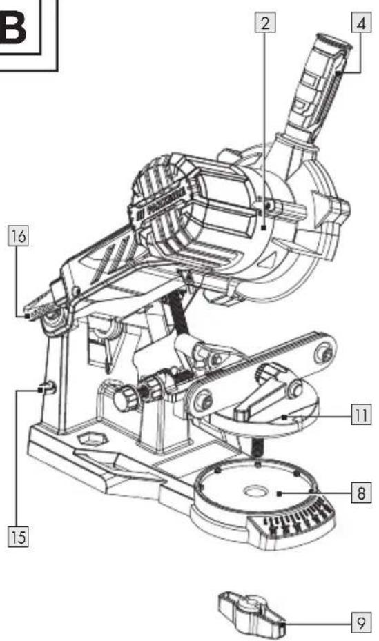
Fig. B
- Remove the cable ties.
- Screw the handgrip 4 onto the grinding head 2.
- Loosen the adjusting screw 9 on the chain tensioning unit 11.
- Place the chain tensioning unit 11 on the grinding base 8.
-
Tighten the chain tensioning unit 11 with the adjusting screw 9.
-
Secure the mains cord 16 in the cord holder 15.
Fixing the adjusting screw
- Insert the adjusting screw 6a and adjusting nut 6b for the depth stop through the threaded hole on the back of the product.
- Fix the grinding depth with the adjusting nut 6b.
- Insert the adjusting screw 13a and adjusting nut 13b to the chain feed.
- Attaching the product to the worktop
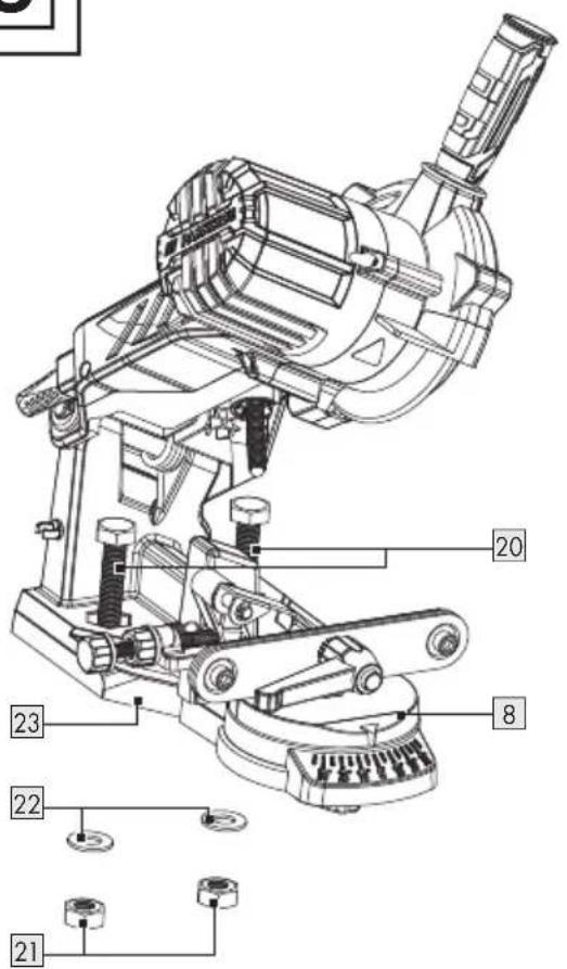
Fig. C
NOTE
Thickness of table edge: 20–30 mm
Drill diameter: 10.5 mm
Screw gauge: M10
- Positioning the product on the worktop: Use the stop notch 23. The grinding base 8 must project over the edge of the table.
- Mark the drill holes with a pen. Remove the product.
- Drill 2 holes into the worktop.
- Screwing the grinding base 8 to the worktop: Use the screws 20, washers 22 and nuts 21.
Operation
⚠️ CAUTION! Risk of injury!
Only use grinding discs ^17 and accessories recommended by the manufacturer. Using other attachment tools and other accessories may represent a risk of injury to you.
▶ Never operate the product without a viewing guard 18.
Do not use any saw blades.
CAUTION! Risk of injury!
Always inspect the grinding disc 17 before starting the product: Check the distance between the viewing guard 18 and the grinding disc.
Do not use any broken, cracked or otherwise damaged grinding discs [17] .
Only switch the product on once it is safely fixed to the worktop.
▶ Never operate the product without a viewing guard 18, chain tensioning unit 11 or grinding disc cover 3.
Make sure that you have a secure footing when working.
Keep your hands away from the grinding disc 17 and teeth of the saw chain when the product is in operation. Do not move the saw chain by hand.
CAUTION! Risk of injury!


Wear eye and hearing protection!
When working with the saw chain: Wear cut-resistant protective gloves and, if necessary, an apron to prevent cuts.
⚠️ CAUTION! Risk of injury!

Always switch off the product and remove the mains plug 16 before cleaning, carrying out any adjustments, maintenance or repair work.
NOTE
The product is powered by an electric motor with thermal protection and restart stop for additional safety.
The sharpening angle can be adjusted from -35^ to +35^ .
The chain guide rail7 has a variably adjustable stop.
▶ Sharpening is carried out by swivelling the grinding head 2.
- Switching on/off

CAUTION! Risk of injury!
The grinding disc ^17 still runs even after the product has been switched off.
Before carrying out the first grinding procedure and after every replacement of the grinding disc 17: Always carry out a trial run of at least 30 seconds duration without load.
▶ Switch off the product immediately if:
-the grinding disc 17 is not rotating smoothly
-considerable vibration occurs
-you hear abnormal noises
Make sure that the mains supply voltage matches the voltage rating indicated on the product's type plate.
NOTE
When working under dust-prone conditions: Ensure that the ventilation holes 19 are clear (see "Cleaning and maintenance").
- Connect the product to the mains supply.
- Switching on: Press the on/off switch 1 into the I position. The product starts up.
- Switching off: Press the on/off switch 1 into the 0 position. The product switches off.
Thermal protection with restart stop
☐ If the product automatically shuts down due to overuse: The product does not restart automatically. Switch on the product again.
● Sharpening the saw chain

CAUTION! Risk of injury!
An incorrectly sharpened saw chain can cause damage and increases the danger of saw kickback! Ensure the saw chain is precisely aligned.
Observe the correct sharpening angle and saw chain minimum dimensions.
Remove as little material as possible.
Do not grind into driving links or connecting links. Otherwise the saw chain may break.
If this is not observed, there is a risk of injuries when working with the product.
NOTE
Clean the saw chain before sharpening. Remove oily wood or oil residues with a brush or cloth.
After sharpening: All the cutting links must have the same length and breadth.
NOTE
When only around 4 mm of the cutting tooth 24 remains: The saw chain has become worn down and must be replaced with a new saw chain.
Inserting the saw chain
Fig. D, step 1
-
Opening the chain guide rail 7: Turn the tension lever 12 in anti-clockwise direction:
-
Return the tension lever to its initial position several times.
-Releasing the tension lever: Pull the tension lever outwards. -
Let the tension lever return to its original position.
-Allow the tension lever to reengage. -
Place the saw chain into the chain guide rail 7. The cutting edges must face the grinding discs 17.
-
Fold the stop 14 down and pull back the saw chain until the cutting tooth 24 to be sharpened rests on the stop.
Adjusting the working angle
-
Unscrew the adjusting nut 9. Use the scale 10 to adjust the required sharpening angle α on the rotary plate of the chain tensioning unit 11. Follow the instructions of the saw chain manufacturer regarding the required sharpening angle α.
-
Retighten the adjusting nut 9.
Adjusting the stop
Fig. D, step 2
- Move the grinding head 2 on the handgrip 4 downwards.
- Use the adjusting screw for the chain feed 13a to bring the cutting tooth 24 closer to the grinding disc 17. The
cutting tooth has to be in contact with the grinding disc.
- Securing the adjusting screw 13a: Use the adjusting nut 13b.
- Fixing the chain links in the chain guide rail 7: Turn the tension lever 12 in clockwise direction.
- Use the adjusting screw 6a to adjust the depth stop. The grinding disc 17 has to touch the base of the tooth.
- Secure the grinding depth with the adjusting nut 6b.
Sharpening
- Switch on the product (see "Switching on/off").
-
Press the handgrip 4 gently to move the grinding head 2 downwards and sharpen the cutting tooth 24. The grinding disc 17 must not be brought to a standstill with the brakes. Reduce the pressure in good time to avoid this.
-
Sharpen the teeth on one side of the saw chain.
-
Adjust the sharpening angle and sharpen the teeth on the other side of the saw chain.
-
Moving the saw chain onward: Switch off the product (see "Switching on/off").
-
Loosen the tension lever 12 and fix the next chain link to be sharpened. Use the adjusted stop 14 and the tension lever in the chain guide rail 7.
Testing the depth gauge distance
Fig. D, step 3
NOTE
The cutting parts of the saw chain are the cutting links which consist of a cutting tooth 24 and a depth gauge nib 25. The vertical distance between these two determines the depth gauge distance A.
- After every third sharpening: Check the depth gauge distance A according to the saw chain manufacturer's instructions.
- File the tip of the depth gauge nib with a flat file. Round off the depth gauge nib slightly after resetting. The original shape must be maintained.
● Cleaning and maintenance
CAUTION! Risk of injury!

Always switch off the product and remove the mains plug 16 before cleaning, carrying out any adjustments, maintenance or repair work.
⚠️ CAUTION! Risk of injury!

Use protective gloves when working with grinding discs 17.
CAUTION! Risk of injury!
Have any work on the product that is not described in this user manual performed by a professional. Only use original parts.
Always check the product before use for obvious defects such as loose, worn or damaged parts. Correct the positioning of screws or other parts. Examine the grinding disc in particular [17] . Exchange the damaged parts.
CAUTION! Risk of burns!
Allow the product to cool down completely before performing any maintenance or cleaning.
- Cleaning
⚠️ CAUTION! Risk of electric shock!
▶ Never clean the product under running water.
⚠ NOTICE! Risk of product damage!
Do not use any cleaning agents or solvents. Chemical substances may attack the plastic parts of the product.
NOTE
Thoroughly clean the product after every use.
□ Clean the ventilation holes 19 and the surface of the product with a soft brush, a paint brush or cloth.
Maintenance
CAUTION! Risk of injury!
Before carrying out the first grinding procedure and after every replacement of the grinding disc 17: Always carry out a trial run of at least 30 seconds duration without load.
Switch off the product immediately if:
-the grinding disc 17 is not rotating smoothly
-considerable vibration occurs
-you hear abnormal noises
⚠ NOTICE! Risk of product damage!
Do not screw the grinding disc nut 17a too tightly. The grinding disc 17 and grinding disc nut could break.
NOTE
Ensure that the rotational speed stated on the grinding disc 17 is the same or higher than the nominal rotational speed of the product. Ensure that the disc dimensions match those of the product.
Only use grinding discs ^17 in perfect working order (sound test).
Only use grinding discs ^17 with a locating hole of 22 mm. Never re-drill a locating hole which is too small for the grinding disc to make it larger.
▶ Never use separate bushings or adapters in order to make grinding discs with a hole that is too large fit the product.
Do not use any saw blades.
After replacing the grinding disc ^17 : Always reassemble the product completely.
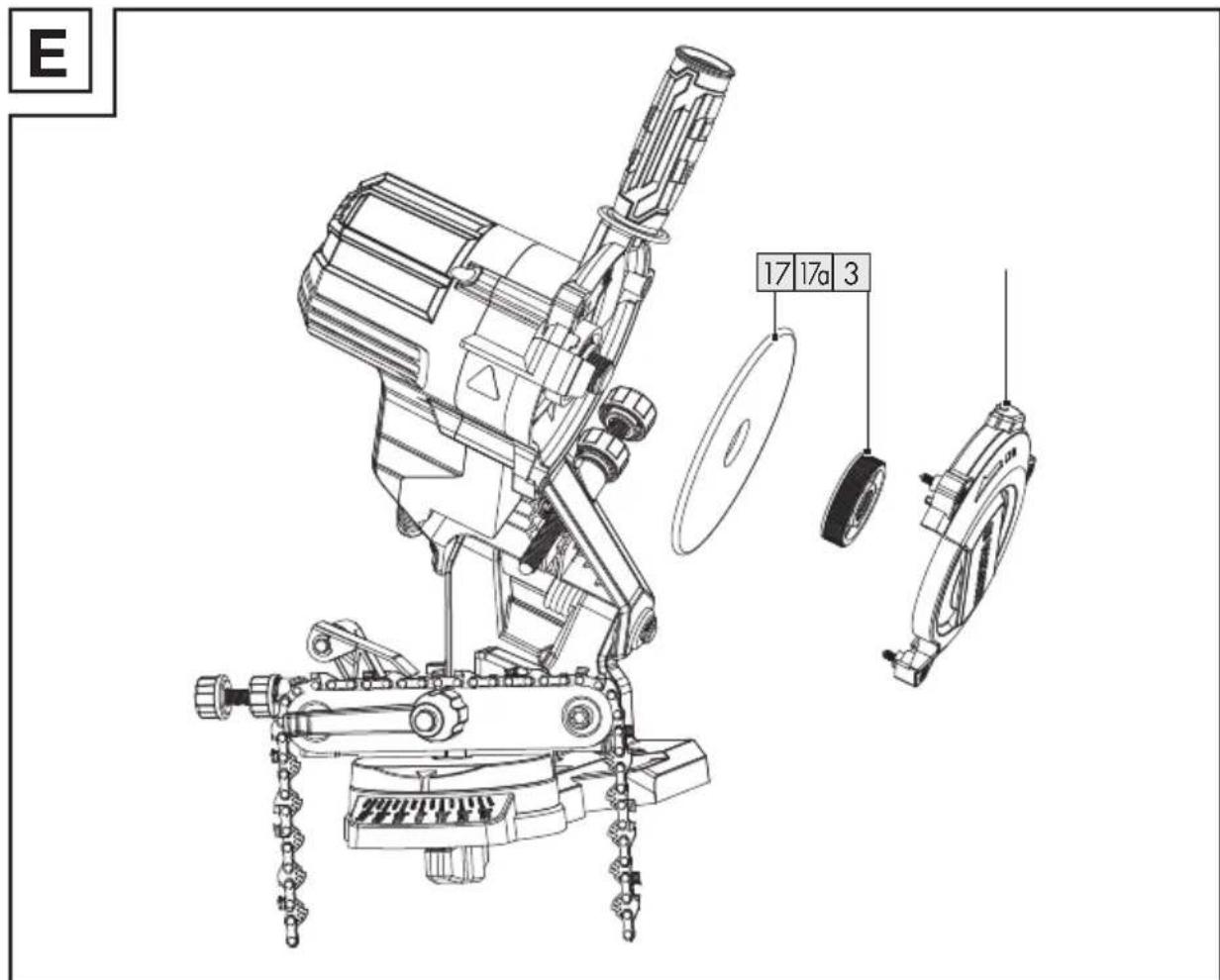
Replacing the grinding disc
Fig. E
- Loosen the handgrip 4.
- Unscrew the 3 mounting screws 5 on the grinding disc cover 3.
- Remove the grinding disc cover 3.
- Unscrew the grinding disc nut 17a by hand.
- Remove the grinding disc 17 from the holder.
- Place the new grinding disc 17 onto the holder. Manually screw on the grinding disc nut 17a.
- Screw the grinding disc cover 3 back on.
Replacement parts/Accessories
- Customers can obtain compatible replacement parts and accessories via www.optimex-shop.com.
■ You can only place orders online.
□ Have the order number ready for your order.
□ Contact the LService hotline (see "Service") for further information.
| Part Order number | |
| 4 Handgrip 99949596202 | |
| 17 Grinding disc 99949596203 | |
| Mounting set: | |
| 20 Screws | |
| 21 Nuts | |
| 22 Washers | 99949596201 |
- Transportation
□ Always transport the product with one hand on the grinding head 2 and the other hand on the grinding base 8.
□ Never carry the product by its mains cord 16.
Storage
☐ Store the product in a dry and dustproof location and out of reach of children.
☐ Store the grinding discs 17 in a dry location. The grinding discs must be stored upright and should never be stacked.
- Disposal
The packaging is made entirely of recyclable materials, which you may dispose of at local recycling facilities.
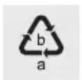
Observe the marking of the packaging materials for waste separation, which are marked with abbreviations (a) and
numbers (b) with following meaning: 1–7: plastics/20–22: paper and fibreboard/80–98: composite materials.
Product:
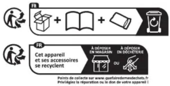
The product incl. accessories and packaging materials are recyclable and are subject to extended producer responsibility.
Dispose them separately, following the illustrated Info-tri (sorting information), for better waste treatment.
The Triman logo is valid in France only.

Contact your local refuse disposal authority for more details of how to dispose of your worn-out product.

To help protect the environment, please dispose of the product properly when it has reached the end of its useful life and not in the household waste. Information on collection points and their opening hours can be obtained from your local authority.
Warranty
The product has been manufactured to strict quality guidelines and meticulously examined before delivery. In the event of material or manufacturing defects you have legal rights against the retailer of this product. Your legal rights are not limited in any way by our warranty detailed below.
The warranty for this product is 3 years from the date of purchase. The warranty period begins on the date of purchase. Keep the original sales receipt in a safe location as this document is required as proof of purchase.
Any damage or defects already present at the time of purchase must be reported without delay after unpacking the product.
Should the product show any fault in materials or manufacture within 3 years from the date of purchase, we will repair or replace it – at our choice – free of charge to you. The warranty period is not extended as a result of a claim being granted. This also applies to replaced and repaired parts.
This warranty becomes void if the product has been damaged, or used or maintained improperly.
The warranty covers material or manufacturing defects. This warranty does not cover product parts subject to normal wear and tear, thus considered consumables (e.g. batteries, tubes, cartridges), nor damage to fragile parts, e.g. switches or glass parts.
● Warranty claim procedure
So that your request can be processed quickly, please observe the following instructions:
For all inquiries, please have the receipt and item number (IAN 495962_2504) ready as proof of purchase.
The article number can be taken from the identification label on the product, engraving on the product, the front cover of your manual (at the bottom left), or the sticker on the back or bottom of the product.
If malfunctions or other defects arise, first contact the service department indicated below by phone or email.
You can then send a product recorded as defective to the communicated service address postage-free, making sure to enclose proof of purchase (receipt) and information on the details of the defect and when it occurred.

text_image
PDF ONLINE parkside-diy.comYou can download and view this and numerous other manuals at parkside-diy.com. This QR code takes you directly to parkside-diy.com. Choose your country and use the search screen to search for the operating instructions. Entering the item number (IAN) 495962_2504 takes you to the operating instructions for your item.
Service
GB Service Great Britain
Tel.: 08000518970
Contact form on parkside-diy.com
IAN 495962_2504
IE Service Ireland
Tel.: 1800851251
Contact form on parkside-diy.com
IAN 495962_2504
● EU declaration of conformity
EU DECLARATION OF CONFORMITY (N° 495962\_2504)
IAN: 495962_2504
Product identification:
"PARKSIDE" Electric Chain Sharpener
Model Number: HG12071
The object of the declaration described above is in conformity with the relevant Union harmonisation legislation:
| Directive 2006/42/EC |
| Directive 2014/30/EU |
| Directive 2011/65/EU and all related amendments |
References to the relevant harmonised standards used or references to the other technical specifications in relation to which conformity is declared:
| N° / Parts |
| Directive 2006/42/EC |
| EN 62841-1:2015/A11:2022 |
| Directive 2014/30/EU |
| EN IEC 55014-1:2021 |
| EN IEC 55014-2:2021 |
| EN IEC 61000-3-2:2019/A1:2021 |
| EN 61000-3-3:2013/A2:2021 |
The object of the declaration described above is in conformity with Directive 2011/65/EU of the European Parliament and of the Council of 8 June 2011 on the restriction of the use of certain hazardous substances in electrical and electronic equipment:
| N° / Parts |
| Directive 2011/65/EU |
| EN IEC 63000:2018 |
Additional information:
| N° / Parts |
| PPP 58094B:2022 |
Keeper of the technical documentation: OWIM GmbH & Co.KG
Signed for and on behalf of:
This declaration of conformity is issued under the sole responsibility of the manufacturer.
Translation of the original declaration of conformity
Neckarsulm 24.06.2025
Place
Date

text_image
ppa. Budmein ppa. T. G. ppa. Jens Buchh eim ppa. Dr. Thorsten Maier Authorised Signatory Authorised SignatoryEN

text_image
QR code image with a central logo, likely linking to a digital resource or website.PDF ONLINE
parkside-diy.com
Directive 2006/42/CE
EN 62841-1:2015/A11:2022
Directive 2014/30/UE
EN IEC 55014-1:2021
EN IEC 55014-2:2021
EN IEC 61000-3-2:2019/A1:2021
EN 61000-3-3:2013/A2:2021
text_image
Diagram showing recycling process with recycling bin, open book, open pencil, and trash bin icons