HDS 13/20-4 ST - Kettle Kärcher - Free user manual and instructions
Find the device manual for free HDS 13/20-4 ST Kärcher in PDF.

User questions about HDS 13/20-4 ST Kärcher
0 question about this device. Answer the ones you know or ask your own.
Ask a new question about this device
Download the instructions for your Kettle in PDF format for free! Find your manual HDS 13/20-4 ST - Kärcher and take your electronic device back in hand. On this page are published all the documents necessary for the use of your device. HDS 13/20-4 ST by Kärcher.
USER MANUAL HDS 13/20-4 ST Kärcher
natural_image
3D rendering of a Karcher industrial machine with control panel and buttons (no visible text or symbols on the device itself)Deutsch 4
English 21
Français 38
Italiano 55
Español 72
Português 89
Nederlands 106
Türkçe 123
Svenska 139
Suomi 155
Norsk 171
Dansk 187
Eesti 203
Latviešu 219
Lietuviškai 236
Polski 253
Magyar 270
Čeština 287
Slovenčina 304
Slovenščina 321
Română 337
Hrvatski 354
Srpski 370
Ελληνικά 387
Русский 405
Українська 423
Қазақша 440
Български 458
中文 476
العربيya 490
natural_image
3D mechanical assembly diagram showing internal components and wiring (no text or labels)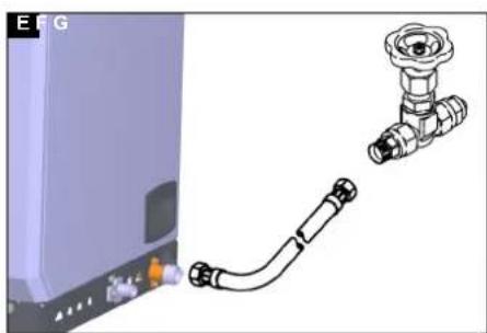
natural_image
Illustration of a wall-mounted industrial pipe fitting with a separate valve assembly (no text or symbols)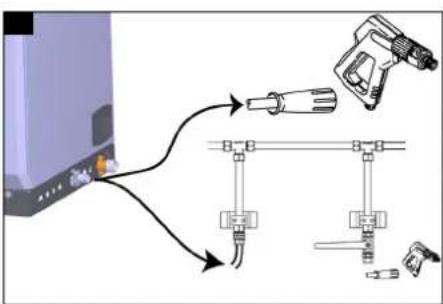
Inhalt
②4Manometer (Option)
Anlageninstallation
Hinweis
71364 Winnenden (Germany)
Tel.: +49 7195 14-0
Fax: +49 7195 14-2212

H. Jenner
Chairman of the Board of Management
S. Reiser
Manager Regulatory Affairs & Certification
Winnenden, 2024/09/01
71364 Winnenden (Germany)
Tel.: +49 7195 14-0
Fax: +49 7195 14-2212
Technische Daten
Safety instructions 21
Safety devices 21
Environmental protection 22
Intended use 22
Accessories and spare parts.... 23
Scope of delivery 23
Description of the device.... 23
Functional description.... 25
System installation.... 26
Startup 27
Operation 28
Transport 29
Storage 29
Care and service.... 29
Troubleshooting guide 31
Warranty 32
Declaration of Conformity 33
Technical data 34
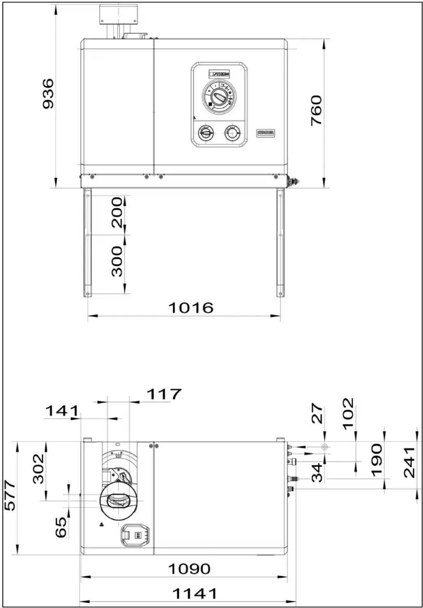
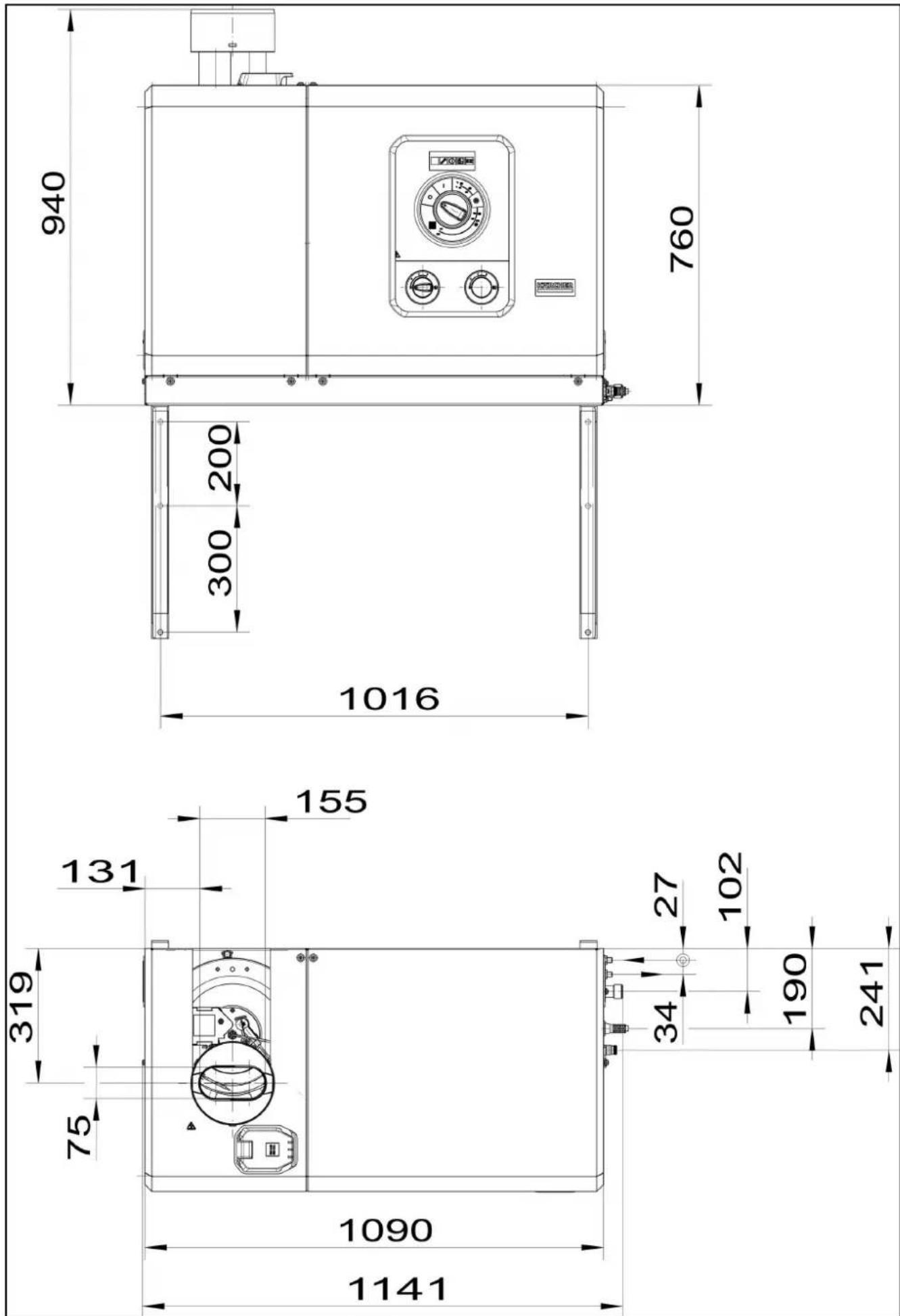
Dimension sheet HDS 8/18-4 ST+HDS 10/21-4 ST ..... 35
Dimension sheet HDS 13/20-4 ST.... 36
Customer Service department 37
General notes
Read these original operating instructions and the enclosed safety instructions before using the device for the first time. Proceed accordingly.
Keep both books for future reference or for future owners.
Safety instructions
⚠️ DANGER ● No changes may be made to the device.
△ WARNING • Exhaust gases are toxic. Never breathe in the exhaust gases. Ensure rooms where the device is operated are sufficiently ventilated and that exhaust gases can be conducted away.
Note • Observe the respectively applicable national regulations for liquid jet cleaners. • Observe the legislature's national accident prevention regulations. Liquid jet cleaners must be tested regularly and the results of the test recorded in writing. • Observe the safety instructions of the used the detergents. • Note that the heating system in the device is classified as a furnace. Furnaces must be inspected regularly according to the applicable national regulations. • According to the applicable national regulations, this high-pressure cleaner must be initially commissioned by a qualified person when used commercially. KÄRCHER has already performed and documented this initial commissioning for you. You can request the documentation for this from your KÄRCHER partner. Please provide the part number and works number of the device when requesting documentation. • We explicitly state that the application national regulations require that this device must be inspected regularly by a qualified person. Please contact your KÄRCHER partner for this.
Symbols on the device
Do not point the high-pressure jet at people, animals, live electrical equipment or at the device itself. Protect the device from frost.

Danger of injury from electrical voltage. Only qualified electricians or authorised and qualified technical specialists are permitted to work on the electrical systems.
According to applicable regulations, the device must never be used with the drinking water network without a system separator. Ensure that the connection to your house water system, with which the high-pressure cleaner is operated, is equipped with a system separator according to EN 12729 type BA. Water that has flowed through a system separator is classified as undrinkable.
Always connect the system separator to the water supply and never directly to the device.

Health risk from poisonous exhaust gases. Never inhale the exhaust gases.
Risk of burns from hot surfaces.

Code for information

Regulations, guidelines and standards
The gas supply company and the district chimney sweep should be consulted before the device is installed.
The regulations of building law, commercial law and emissions protection law must be observed during installation. We draw your attention to the regulations, directives and standards listed below:
- The device may only be installed by a specialised company in accordance with the relevant national regulations.
- The respective national regulations set by the legislator must be observed during the electrical installation.
- Adjustments, maintenance work and repairs to the burner may only be carried out by trained Kärcher service technicians.
- The locally applicable regulations must be adhered to when planning a chimney.
Workstation
The device is used to switch the system on and off and to set the water temperature. The detergent dosage can also be set and error messages can be viewed.
Depending on the system design, further workstations are located at the accessory devices (spraying devices), which are connected to the tapping points. Remote controls can optionally be installed at these workstations.
Safety devices
△CAUTION
Risk of injury due to missing or modified safety devices!
Safety devices are provided for your own protection.
Do not bypass, remove or render ineffective any safety devices.
The safety devices are set and sealed by the manufacturer. Adjustments are performed only by customer service.
Water shortage safeguard
The water shortage safety device (flow switch) prevents the burn-er from overheating and the high-pressure pump from running dry in the event of a water shortage. The appliance switches off if the water supply is insufficient.
Pressure switch
The pressure switch switches off the device when the maximum working pressure is exceeded.
Safety valve Safety block
If the maximum permissible system pressure is exceeded, the safety valve opens to reduce the pressure in the system. The safety valve is factory-set and sealed. It may only be adjusted by customer service.
Flame monitoring
The flame monitoring system monitors the brightness of the flame on the burner and switches the burner off in the event of a fault.
Overcurrent protection
The motor of the high-pressure pump is protected by the electronics and a winding circuit breaker.
Exhaust gas thermostat
If the emission temperature rises above the permissible value, the emission temperature limiter switches off the burner and locks it.
Temperature limiter
The temperature limiter switches the burner off when the temperature is too high.
Air pressure switch
The air pressure switch switches off the burner as soon as the fan fails to generate air pressure.
exhaust pressure switch
The exhaust gas pressure switch switches off the burner if an impermissible high counterpressure builds up in the exhaust gas system, e.g. due to a blockage.
Pressure relief of high pressure system (option)
After switching off the device via the high-pressure gun, a solenoid valve located in the high-pressure system opens after the operating standby time has elapsed. This reduces the pressure built up in the high-pressure system.
Safety latch
The safety catch on the high-pressure gun prevents the device from being switched on accidentally.
Readiness time
If the device is not used for 30 minutes, the device switches off. The readiness time can be activated and deactivated by customer service via the service menu.
Environmental protection

The packing materials can be recycled. Please dispose of packaging in accordance with the environmental regula-

Electrical and electronic devices contain valuable, recyclable materials and often components such as batteries, rechargeable batteries or oil, which - if handled or disposed of rectly - can pose a potential danger to human health and the environment. However, these components are required for the act operation of the device. Appliances marked by this sym- re not allowed to be disposed of together with the household dish.
Kärcher detergents are separator-friendly (ASF). That means the function of an oil separator is not impaired. A list of recommended detergents can be found in Chapter Accessories and spare parts.
Notes on the content materials (REACH)
Current information on content materials can be found at: www.kaercher.de/REACH
Intended use
- The device is used to remove dirt from surfaces using a free-flowing water stream. It is used in particular for cleaning machines, vehicles and facades.
- The system must be installed so that the rear opening is closed, for example by a wall.
- Only clean water may be used as a high-pressure medium. Contamination leads to premature wear and tear or deposits in the device.
△DANGER
Use at petrol stations or other hazardous areas
Risk of injury
Adhere to the respective safety regulations.
Note
Do not allow waste water containing mineral oil to enter the ground, water or sewage system. Only wash the engine or under-body in suitable areas with oil separators.
Water supply limit values
ATTENTION
Dirty water
Premature wear and tear or deposits in the device Supply the device using only clean water, or recycled water that does not exceed the specified limit values.
The following limit values apply to the water supply:
- pH value: 6.5-9.5
- Electrical conductivity: Conductivity of fresh water + 1200 S/cm, maximum conductivity 2000 S/cm
- Settleable particles (sample volume 1 l, settling time 30 minutes): < 0.5 mg/l
- Filterable particles: < 50 mg/l, no abrasive substances
• Hydrocarbons: < 20 mg/l
• Chloride: < 300 mg/l
• Sulphate: < 240 mg/l
• Calcium: < 200 mg/l
• Total hardness: < 28 °dH, < 50° TH, < 500 ppm (mg CaCQ/l) - Iron: < 0.5 mg/l
• Manganese: < 0.05 mg/l
• Copper: < 2 mg/l
• Active chloride: < 0.3 mg/l
• Free of unpleasant odours
Accessories and spare parts
Only use original accessories and original spare parts. They ensure that the appliance will run fault-free and safely.
Information on accessories and spare parts can be found at www.kaercher.com.
Detergent
Detergents make cleaning tasks easier and a selection of detergents is shown in the table. The instructions on the packaging must be observed before using the detergents.
| Area of application | Contamination, type of application | Detergent | Kärcher designation | Dosing |
| Automotive industry, petrol stations, haulage companies, vehicle fleets | Dust, road dirt, mineral oils (on painted surfaces) | Active cleaner, neutral * RM 55 | * 0,5-8% | |
| Active cleaner, alkaline RM 81† | 0,25-1,25% | |||
| Natural active cleaner, alkaline | RM 82N | |||
| RM 803* | ||||
| Foam cleaner RM 838 direct | ||||
| RM 806 | ||||
| Vehicle preservation Hot wax | RM 41 | |||
| Hot wax | RM 820* | |||
| Spray wax RM 821* | ||||
| Super pearl wax | RM 824* | |||
| Metalworking industry | Oils, grease, dust and similar soiling | Active cleaner, neutral * | RM 55 * | 0,5-8% |
| Active cleaner, alkaline RM 81† | 0,25-1,25% | |||
| RM 803* | ||||
| RM 806 | ||||
| For heavy soiling | RM 31* 0,375-2,5% | |||
| Liquid (with corrosion protection) | RM 39 | |||
| Food processing companies | Light to medium soiling, grease/oil, large surfaces | Parts cleaner | RM 39 | |
| Active cleaner, neutral * RM 55 | * 0,5-8% | |||
| Active cleaner, alkaline RM 81* | 0,25-1,25% | |||
| Natural active cleaner, alkaline | RM 82N | |||
| Foam cleaner, neutral | RM 57 | |||
| Foam cleaner RM 58* | ||||
| Gel foam OSC | RM 882 | |||
| RM 31*/** | 0,375-2,5% | |||
| Smoke resin | Smoke resin remover | RM 33** | ||
| Cleaning and disinfection | RM 732 | |||
| Disinfection | RM 735 | |||
| Limescale, mineral deposits | RM 25** | |||
| Foam cleaner RM 59* | ||||
| Sanitary area | Limescale, urine scale, soaps etc. | Basic cleaner | RM 25* | |
| Foam cleaner RM 59 |
* Separator-friendly
** only for short use, two-step method, rinse with clear water.
Scope of delivery
During unpacking, check the contents for completeness. In the event of shipping damage, please notify your dealer.
Note
A standard nozzle is included in the scope of delivery. Further accessories are not included in the scope of delivery.
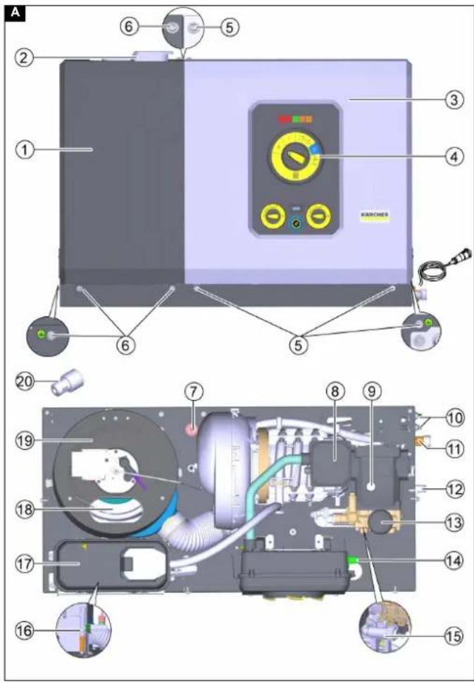
Description of the device
Illustration A
① Cover, left
②Filling point for system care
③Cover, right
④Control panel + electrical box
⑤ Cover fastening screws, right
⑥ Cover fastening screws, left
⑦ Fuel filter
⑧Terminal box of motor
⑨Filling point for pump oil
⑩Fuel line (supply + return)
⑪ Water inlet
⑫High-pressure outlet
⑬Pressure tank
⑭System care setting + service switch
⑮Fresh water filter
⑯ Safety block
⑰ Float tank with system care container
⑱ Exhaust gas outlet
⑲ Booster heater
⑳Standard nozzle
The following attachment kits are available separately:
• Remote control (not shown)
• Pressure relief (not shown)
• Second detergent + dosage
• Steel floor structure (not shown)
• Water inlet solenoid valve (not shown)
- Operating hours counter + pressure gauge
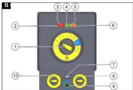
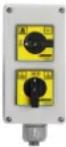
Control panel
Illustration B
①Main switch
②Service menu indicator light (red)
③Service indicator light (red)
④Operation indicator light (green)
⑤Detergent indicator light (orange)
⑥System care indicator light (orange)
⑦Operating hours counter (option)
⑧Detergent dosing valve 2 (option)
⑨Pressure gauge (option)
⑩Detergent dosing valve 1
Meaning of the LED indicators
| Indicator light Blink | code Meaning |
| Indicator light Service menu (red) | - This indicator light is only relevant for service technicians. |
| Indicator light Service (red) | lights up Carry out service/maintenance after 600 h pump operation after 400 h burner operation |
| flashes 1x Leakage on the device The device switches off. | |
| flashes 2x Current/voltage fault: Asymmetry Over/under current Over/undervoltage The device switches off. | |
| flashes 3x Winding protection contact fault The device switches off. | |
| flashes 4x Exhaust gas fault The device switches off. | |
| flashes 5x Water shortage / dry running The device switches off. | |
| flashes 6x Flame sensor LED too bright / too dark The device switches off. | |
| flashes 7x Water outlet temperature sensor fault The device switches off. | |
| flashes 8x Communication fault The device switches off. | |
| Indicator light Operation (green) | lights up Normal operation without faults |
| flashes 1x Pump has been running continuously for 30 minutes | |
| flashes 2x Pump has been continuously inactive for 30 minutes | |
| Detergent indicator light (orange) | lights up Detergent 1 empty |
| flashes 1x Detergent 2 empty | |
| System care indicator light (orange) | lights up System care empty |
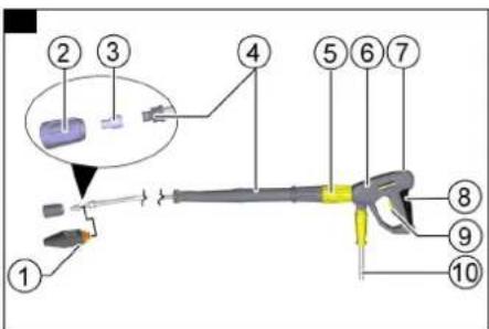
High-pressure gun and lance (accessory)
Note
No accessories are included in the scope of delivery. Illustration C
①Vibrasoft rotary nozzle
②Union nut
③High-pressure nozzle
④EASY!Lock spray lance
⑤Pressure/quantity regulation
⑥EASY!Force high-pressure gun
⑦ Safety latch
⑧Trigger
⑨ Safety lever
⑩EASY!Lock high-pressure hose
Functional description
- The cold water reaches the suction side of the high-pressure pump via the motor cooling coil and the float tank. System car (RM 110) is dosed into the float tank. Depending on the water hardness, this can be adjusted by customer service as required. The pump conveys water and detergent sucked in through the instantaneous water heater. The proportion of de-
tergent in the water can be adjusted using a dosing valve. The instantaneous water heater is heated by a burner.
- The high-pressure outlet is connected directly to a high-pressure hose or to an existing high-pressure network in the building. The high-pressure gun is connected to the tapping points of this network using a high-pressure hose.
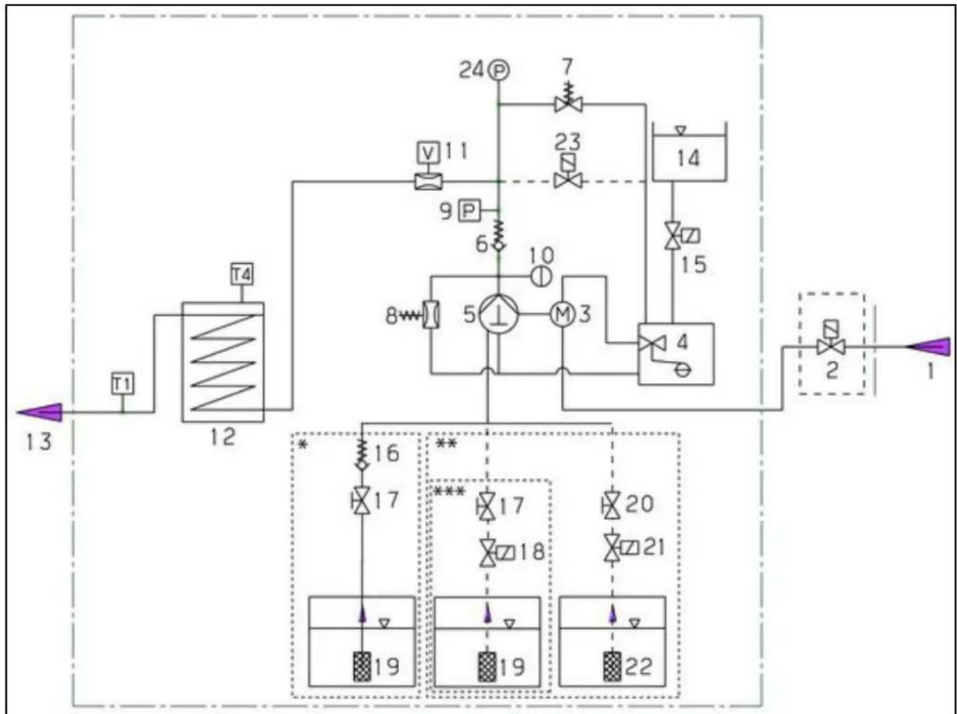
Flow chart
flowchart
graph TD
    A["13"] --> B["T1"]
    B --> C["12"]
    C --> D["T4"]
    D --> E["24P"]
    E --> F["7"]
    F --> G["23"]
    G --> H["14"]
    H --> I["15"]
    I --> J["4"]
    J --> K["2"]
    K --> L["1"]

    subgraph Component 1
        M["16"] --> N["17"]
        N --> O["19"]
        P["10"] --> Q["5"]
        R["M3"] --> S["1"]
    end

    subgraph Component 2
        T["17"] --> U["18"]
        V["20"] --> W["21"]
        X["19"] --> Y["22"]
        Z["***"] --> AA["17"]
        AB["22"] --> AC["19"]
①Water inlet
②Water inlet solenoid valve (option)
③Electric motor
④Float tank
⑤High-pressure pump
⑥Check valve
⑦ Safety valve
⑧Overflow valve
⑨Pressure switch
⑩Pressure tank for high pressure
⑪Water shortage safeguard
⑫ Booster heater
Water outlet temperature sensor T1
T4 exhaust gas temperature monitor
* Flow chart with 1 detergent without remote control (delivery status)
** Flow chart with 2 detergents and remote control (optional)
*** Flow chart with 1 detergent and remote control (optional)
⑬High-pressure outlet
⑭DGT container (system care)
⑮DGT solenoid valve (system care)
⑯Detergent check valve
⑰Dosing valve 1
⑱ Solenoid valve for detergent 1 (option)
⑲Detergent inlet 1
⑳Dosing valve 2 (option)
②1 Solenoid valve for detergent 2 (option)
②2 Detergent inlet 2 (option)
②3Pressure relief valve (option)
⑳Pressure gauge (option)
System installation
Note
Installation may only be carried out by authorised specialist personnel!
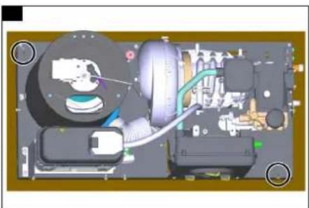
Unloading
On delivery, the device is bolted to the transport pallet to secure it.
- Remove the cardboard and the squared timbers.
- Release the screws of the cover and remove the cover.
- Remove the 2 screws at the front right and rear left to release the device frame from the pallet.
Illustration D
- Lift the device off the pallet and refit the cover.
General
- The heating equipment in the device is a firing system. The locally applicable regulations must be observed during installation.
- Only use tested chimneys and exhaust gas pipes.
Notes Oil installation
- When installing a fuel oil tank in the device installation room, observe the regulations on the storage of flammable liquids.
Fuel lines
Provide a two-pipe system with supply and return lines for the fuel lines.
• Maximum heating oil pre-pressure: 0.05 MPa (0.5 bar)
- Maximum negative pressure between heating oil filter and pump: 0.04 MPa (0.4 bar)
- Before the initial startup of the device, connect the external fuel lines to the device and supply them with fuel. This also applies to cold water operation, as otherwise the fuel pump will no longer be lubricated and will fail after a short time.
Air/exhaust gas routing
- The components for air/exhaust gas system are not included with the device. Observe the local regulations for building installation.
• Each device must be connected to its own chimney. - Carry out the exhaust gas routing in accordance with local regulations and in consultation with the responsible chimney sweep.
Wall mounting
- Check the load capacity of the wall before installation. Use suitable plugs and screws for concrete, cavity block, brick and aerated concrete walls, e.g. an injection anchor.
- The device must not be rigidly connected to the water supply or high-pressure pipework. The connecting hoses must always be fitted.
- Provide a stopcock between the water pipe network and the connecting hose.
Installation of the high-pressure lines
Illustration F
Observe the relevant national regulations when installing the high-pressure lines.
- The pressure drop in the pipework must be less than 1.5 MPa.
- The finished pipework must be tested at 32 MPa.
- The insulation of the pipework must be temperature-resistant up to 100^ C.
Setting up the detergent containers
- Set up the containers so that the lower level of the detergent is not more than 1.5 m below the base of the device and the upper level is not above the base of the device.
Remote control (option)
Remote controls can be connected between the device and the tapping points. These allow the device to be operated directly at the tapping point.
Various mounting kits for remote controls are available depending on the application.
| Function Description | ||
 | Reset After the stand | by time has elapsed, the device can be re-started directly at the tapping point. |
 | Emergency off | |
 | On/Off + detergent (turn switch)Single workstation | Switching the device on and off at the tapping point.Activation of the hot water function (burner switches on).Selection of whether detergent should be added:No admixture, admixture RM 1 or admixture RM 2, as set on the device. |
 | On/Off + detergent (push buttons)up to 5 spots | Switching the device on and off at the tapping point.Activation of the hot water function (burner switches on).Selection of whether detergent should be added:No admixture, admixture RM 1 or admixture RM 2 (option), as set on the device. |
Water connection
Illustration E
-
Connect the water inlet to the water pipe network using a suitable hose.
-
The capacity of the water supply must be at least 1300 l/h at a minimum of 0.15 MPa.
- The water temperature must be under 30 °C.
- If the "Solenoid valve water inlet" attachment kit is installed, the valve blocks the water inlet until water is required at a tapping point or the device is switched on.
Electrical connection
Note
Switch-on procedures will generate short-term voltage drops. Unfavourable mains conditions may cause other devices to be impaired.
ATTENTION
Exceeding the grid impedance
Electrical shock in the event of a short-circuit
The maximum permissible mains grid impedance at the electrical connection point (see Technical data) must not be exceeded. Contact your electricity supplier in the case of any uncertainties regarding the mains grid impedance at your electrical connection point.
- For connected loads, see technical data and type plate.
- The electrical connection must be carried out by an electrician and comply with IEC 60364-1.
- All live parts, cables and devices in the work area must be in proper condition and be protected against water jets.
△DANGER
Danger of death from electric shock.
If the device is operated at a socket without an error current circuit breaker or without a protective contact (earthing), there is a danger of death from electric shock in the event of a fault! Only operate the device at sockets with an earthing contact and with an error current circuit breaker with a nominal fault current of max. 30 mA.
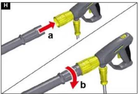
Mounting the high-pressure gun, spray lance, nozzle and high-pressure hose
Device with ANTI!Twist: Attach the yellow high-pressure hose connection to the high-pressure gun.
Note
The EASY!Lock system connects components quickly and safely via a single turn of the quick-release thread.
- Connect the spray lance to the high-pressure gun and hand-tighten (EASY!Lock).
Illustration H
-
Plug the high-pressure nozzle onto the spray lance.
-
Fit the union nut and hand-tighten (EASY!Lock).
- Device without a hose reel: Connect the high-pressure hose to the high-pressure gun and high-pressure connection of the device and tighten hand-tight (EASY!Lock).
- Device with a hose reel: Connect the high-pressure hose to the high-pressure gun and hand-tighten (EASY!Lock).
ATTENTION
Rolled-up high-pressure hose
Risk of damage
Fully unroll the high-pressure hose before starting operation.
Installation example
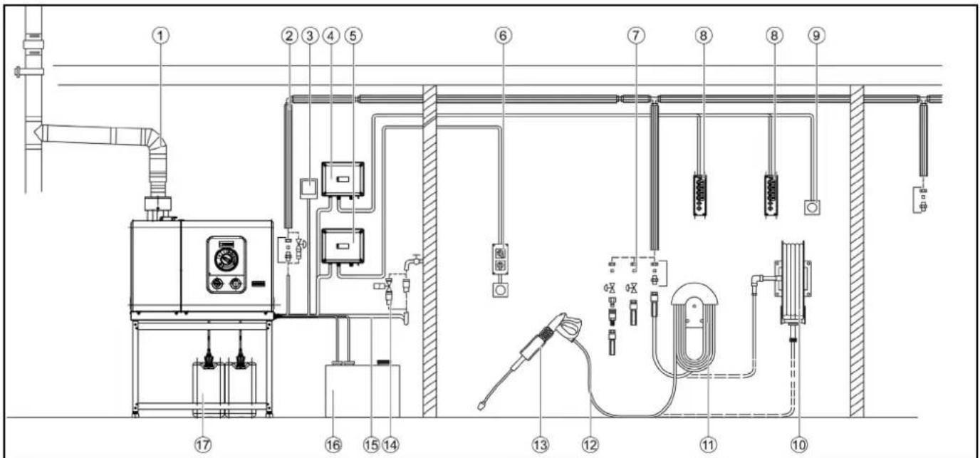
① Exhaust gas pipe
②Pipework with thermal insulation
③Reset button
④Control cabinet with multiple remote control
⑤Control cabinet with single remote control
⑥ Remote control attachment kit (single) including emergency stop
⑦Connection point with stopcock and quick coupling
⑧ Remote control attachment kit (multiple)
⑨Emergency stop button
⑩Hose reel
⑪ Hose switch
⑫High-pressure hose
⑬Tapping point with high-pressure gun, spray lance and nozzle
⑭Supply water solenoid valve
⑮Water hose
⑯ Heating oil tank
⑰Detergent tank
Startup
⚠ WARNING
Risk of injury
Damaged components can lead to injuries when operating the device.
Check that the device, accessories, supply lines and connections are in perfect condition. Do not use the device if it is not in perfect condition.
1 Ensure the water inlet is OK.
2 Remove the detergent suction from the device.
3 Connect the heating oil.
4 Ensure the power supply is OK.
Note
RM 110 prevents calcification of the heating coil, device and pipework in the presence of hard water.
Note
RM 111 prevents the formation of black water and cares for the pump in the presence of soft water.
| Water hardness (°dH) | Scale on the turn switch (1-10) | System care products to be used |
| <3 3 RM 111 | ||
| 3...7 1 RM 110 | ||
| 7...14 2 RM 110 | ||
| 14...21 3 RM 110 | ||
| >21 4 RM 110 |
- Determine the local water hardness via the local supply company or with a hardness tester (order number 6.768-004.0).
- Set the system care dosage using the turn switch on the control panel.
Refilling the system care
- The system care is a highly effective agent for preventing calcification of the heating coil when operating with calcareous tap water. This is drip-fed dosed into the float container.
- The dosage is set to medium water hardness at the factory and can be adjusted to the water hardness on site if necessary.
- Refill the system care.
Operation
Standby mode
- If the high-pressure gun is closed during operation, the device will switch off.
- If the gun is opened again within the activatable standby time (30 minutes), the device restarts automatically.
- If the operating standby time is exceeded, the safety timer switches off the pump and burner.
- To restart the device, set the device switch to the "0" position, then switch it on again. If the device is controlled by a remote control, it can be restarted using the corresponding switch on the remote control.
Switch to standby mode
ATTENTION
Risk of injury
Risk of injury from escaping, possibly hot water stream!
Check the device for damage each time before use.
- Check the high-pressure hose, the pipework, the fittings and the spray lance for damage before each use.
- Replace leaking components immediately and seal leaking joints.
- Check the hose coupling for tight fit and leaks.
- Check the filling level of the detergent container and top up with detergent if necessary.
- Check the filling level of the system care and top up if necessary.
Nozzle selection
△CAUTION
Risk of damage as a result of incorrect nozzle
Vehicle tyres can be damaged when cleaning with a round jet. Always clean vehicle tyres with a flat jet nozzle (25°) and a spray distance of at least 30 cm.
We recommend the following nozzles, depending on the device and the cleaning task:
| Nozzle | Part number | Spray angle | Pressure (MPa) |
| HDS 8/18-4 St | |||
| 045 2.113 | -053.0 40° 17 | ||
| 043 2.113 | -008.0 25° 18 | ||
| 045 2.113 | -033.0 0° 17 | ||
| 048 2.113 | -010.0 25° 15 | ||
| 055 2.113 | -055.0 40° 11 | ||
| 055 2.113 | -025.0 25° 11 | ||
| 055 2.113 | -035.0 0° 11 | ||
| HDS 10/21-4 St | |||
| 050 2.113 | -054.0 40° 21 | ||
| 050 2.113 | -023.0 25° 21 | ||
| 050 2.113 | -034.0 0° 21 | ||
| 060 2.113 | -026.0 25° 15 | ||
| 060 2.113 | -048.0 15° 15 | ||
| 060 2.113 | -036.0 0° 15 | ||
| 070 2.113 | -028.0 25° 11 | ||
| 070 2.113 | -049.0 15° 11 | ||
| 072 2.113 | -013.0 25° 10 | ||
| HDS 13/20-4 St | |||
| 070 2.113 | -028.0 25° 20 | ||
| 075 2.113 | -056.0 40° 16 | ||
| 075 2.113 | -037.0 0° 16 | ||
| 080 2.113 | -057.0 40° 14 | ||
| 080 2.113 | -015.0 25° 14 | ||
| 080 2.113 | -051.0 15° 14 | ||
| 080 2.113 | -038.0 0° 14 | ||
| 100 2.113 | -017.0 25° 9 | ||
| Nozzle | Part number | Spray angle | Pressure (MPa) |
| 100 2.113 | -052.0 15° 9 |
Changing nozzles
△DANGER
Risk of injury!
Switch off the device and actuate the high-pressure gun until the device is depressurised before changing the nozzle.
. - -
1. Secure the high-pressure gun by pushing the safety latch forwards.
2. Change the nozzle.
Cold water operation
For removing light contamination and for rinsing, e.g. garden machines, terrace, tools.
- Set the power switch to "I".
Operation with hot water
⚠️DANGER
Hot water
Risk of scalding
Avoid contact with hot water.
- Set the power switch to the desired temperature.
Eco level
The device works in the most economical temperature range (max. 60 °C).
Operation with detergent
△DANGER
Risk of injury from detergent
Serious damage to health due to improper use of detergents.
Observe the detergent manufacturer's safety data sheet.
Wear the prescribed personal protective gear.
Note
KÄRCHER detergents ensure fault-free operation. Ask us for advice, request our catalog or our detergent information sheets.
- Hang the detergent suction hose in a container with detergent.
- Set the detergent dosing valve to the desired dosage. The dosage is set in stages from 0 (no detergent) to 6 (highest dosage).
Recommended cleaning method
- Spray the detergent sparingly on the dry surface and let it work for a while (do not let it dry).
- Rinse off the loosened dirt with the high-pressure jet.
After operation with detergent
- Immerse the filter in clear water.
- Turn the dosing valve to the highest detergent concentration.
- Start the device and rinse clear for one minute.
Operation with detergent at the tapping point
As an alternative to dosing detergent at the device, detergent can also be added directly at the dispensing points.
Various options are available for this, e.g.a cup foam lance.
△WARNING
Risk of injury from detergent
Health risk due to incorrect handling of detergents.
Adhere to the safety instructions stated on the detergent packaging.
ATTENTION
Risk of damage from unsuitable detergents
Using unsuitable detergents may damage the device and the item being cleaned.
Use only detergents approved by KÄRCHER.
Observe the dosing recommendations and notes provided with the detergent.
Use detergents sparingly to help conserve the environment.
Note
KÄRCHER detergents ensure fault-free operation. Ask us for a consultation, request our catalogue or our detergent information sheets.
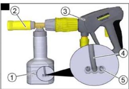
Illustration G
①Container
② Foam nozzle
③High-pressure gun
④Suction hose
⑤Gate
Detergent admixture: 3=high, 2=medium, 1=low
- Unscrew the container.
- Plug the desired gate into the suction hose.
- Fill the detergent into the container.
- Screw the container onto the foam nozzle.
- Disconnect the spray lance from the high-pressure gun.
- Connect the cup foam lance to the high-pressure gun and hand-tighten.
- Start up the high-pressure cleaner.
After operating with detergent
The cup foam lance must be flushed after use to prevent the formation of detergent deposits.
- Unscrew the container.
- Pour the remaining detergent back into the original packaging.
- Fill the container with clear water.
- Screw the container onto the cup foam lance nozzle.
- Operate the cup foam lance for approx. 1 minute to flush the detergent residue.
- Empty the container.
Opening/closing the high-pressure gun
- Actuate the safety lever and trigger.
The high-pressure gun opens. - Release the safety lever and trigger.
The high-pressure gun closes.
Pressure/quantity regulator on the high-pressure gun △DANGER
Danger of a loose spray lance
Risk of injury
Take care to ensure that the spray lance screw connection does not release when adjusting the pressure/quantity control.
- Set the power switch to max. 98 °C.
- Adjust the working pressure and flow rate by turning (variable) the pressure/quantity regulator on the high-pressure gun (+/-).
Switching off the device
△DANGER
Danger of scalding from hot water
Contact with hot water can lead to scald injuries.
After operation with hot water, the device must be operated with an opened gun with cold water for at least 2 minutes.
- Close the water inlet.
- Open the high-pressure gun.
- Switch on the pump with the power switch and let it run for 5-10 seconds.
- Close the high-pressure gun.
- Set the trigger to "0/OFF".
- Close the stopcock on the water inlet and, if necessary, also close other stopcocks at the tapping points
- Remove the water connection.
- Actuate the high-pressure guns at the tapping points until the system is depressurised.
- Lock the high-pressure guns by pushing the safety latch forwards.
Switching off in the event of an emergency
- Turn the main switch to position "0".
- Close the water inlet.
- Actuate the high-pressure gun until the device is completely depressurised.
Transport
△CAUTION
Risk of injury, risk of damage
Be aware of the weight of the device during transportation.
- When transporting in vehicles, secure the device against slipping and tipping over according to the applicable guidelines.
Storage
△CAUTION
Risk of injury or damage due to non-observance of the weight!
When transporting and storing the device, there is a risk of injury and damage due to its weight.
Take into account the weight of the device for transportation and storage, see chapter Technical data.
ATTENTION
Risk of damage due to frost!
Water that is not completely drained can damage the device and accessories during freezing.
Empty the water completely from the device and accessories.
Protect the device and accessories from frost.
Care and service
Service contract
We recommend that you choose a service contract to ensure reliable operation of the device. Please contact your KÄRCHER customer service department responsible.
Maintenance intervals
Daily
- Check the high-pressure gun.
- Check the mains cable.
- Check the filling level of the detergent containers.
- Check the filling level of the system care.
- Check the high-pressure hoses.
Weekly
ATTENTION
Risk of damage due to milky oil
Operation with milky oil can lead to damage to the device.
If the oil is milky, inform the authorised Customer Service immediately.
- Check the system for leaks.
- Check the appearance and level of the pump oil.
- Check the vibration dampener.
Monthly
- Check the pump for leaks.
- Check the system for internal deposits. To do this, start up the system with a spray lance without a high-pressure nozzle. If the operating pressure on the device pressure gauge (optional) rises above 3 MPa, the system must be descaled.
- Clean the fresh water filter.
- Clean the fuel filter.
Every six months or after maintenance display on the device
- Change the oil in the high-pressure pump.
- Have the entire system checked and cleaned by customer service.
Annually
- Replace the fuel filter (earlier if necessary).
- Perform the safety test.
Every 5 years at the latest
- Perform the pressure test according to the manufacturer's specifications.
Maintenance work
Changing the oil
See the "Technical data" section for the oil volume and type.
- Provide a catch pan for approx. 1 litre of oil.
- Loosen the oil drain plug.
- Drain the oil into the catch pan.
Note
Dispose of the old oil in an environmentally friendly manner or hand it over to an authorised collection point.
- Tighten the oil drain plug again.
- Slowly fill with new oil up to the centre of the sight glass or between the "Min" and "Max" markings on the dipstick.
Vent the device
- Switch the device on "I/ON".
- Unlock the lever of the high-pressure gun.
- Press the lever of the high-pressure gun. The device switches on.
- Allow the device for run a maximum of 2 minutes until the water escaping from the high-pressure gun is free of air bubbles.
- Release the lever of the high-pressure gun.
- Lock the lever of the high-pressure gun.
Cleaning the fresh water filters
- Close the water inlet.
- Release the screws of the cover and remove the cover.
- Unscrew the filter casing in front of the pump and remove the water filter.
- Clean the filter and replace if necessary
- Mount the device in reverse order.
Descale the device
Deposits accumulating in the pipework increase the flow resistance and the motor load becomes too high.
△DANGER
Hazard due to inflammable gases
Risk of explosion
Do not smoke during the descaling process. Ensure good ventilation.
△DANGER
Acid danger
Risk of acid burns
Wear safety goggles and protective gloves.
Execution:
According to legal regulations, only approved boiler solvents with a test certificate may be used for removing deposits.
• RM 101; Dissolves descaling and detergent residues.
1. Fill a 20 litre container with 15 litres of water.
2. Add 1 litre of scale solvent.
3. Connect the water hose directly to the pump head and hang the free end into the container.
4. Place the connected spray lance in the container without a nozzle.
5. Start the motor according to the operating instructions of the motor manufacturer.
6. Open the high-pressure gun and do not close it again during descaling.
7. Set the temperature controller to a work temperature of 40^ C.
8. Let the device run until the work temperature is reached.
9. Switch the device off and allow it to stand for 20 minutes. The high-pressure gun must remain open.
10. Then pump the device empty.
Note
For the purposes of corrosion protection and neutralising acid residues, we recommend then pumping an alkaline solution (e.g. RM 81) through the device via the detergent container.
Frost protection
The device should be installed in a frost-protected room. If there is a risk of frost, e.g. when installed in an outside area, the device must be drained and flushed with antifreeze.
- Unscrew the water supply hose and the high-pressure hose.
- Allow the device for run for a maximum of 1 minute until the pump and lines are empty.
- Unscrew the supply line at the boiler base and allow the heating coil to drain.
- Pour a commercially available antifreeze into the float tank. Observe the handling instructions of the anti-freeze manufacturer when doing this.
- Place a catch pan under the high-pressure outlet.
- Switch on the device (without burner) until the device is completely flushed.
Note
The antifreeze also provides a certain degree of corrosion protection.
Troubleshooting guide
△DANGER
Inadvertently starting up device, touching live components Risk of injury, electric shock
Switch off the device before performing any work on the device. Remove the mains plug.
Have all checks and work on electrical parts performed by a qualified electrician.
In case of any malfunctions not mentioned in this chapter, contact the authorised Customer Service.
Who is permitted to eliminate faults?
Operator: Work labelled with "Operator" may only be performed by instructed persons capable of operating and maintaining high-pressure systems.
Qualified electrician: Work labelled with "Electrician" may only be performed by qualified electricians.
Customer Service: Work labelled with "Customer service" may only be performed by KÄRCHER customer service technicians or KÄRCHER-authorised technicians.
Troubleshooting guide
| Fault | Cause | Rectification | Person responsible |
| Device is not running | There is no voltage in the machine. | 1. Check the plug and socket.2. Check if the voltage specified on the type plate matches the voltage of the power source.3. Check the mains connection for damage. | Operator, qualified electrician |
| Safety timer active. 1. Briefly switch | off the device at the trigger an then on again. | Operator | |
| Fuse blown in the control circuit. 1. | Insert new fuse. Eliminate the reason for the overload if it burns out again. | Customer Service department | |
| HP pressure switch (high pressure) faulty. | 1. Check the pressure switch. Customer Service department | ||
| Burner does not ignite or flame goes out during operation | Temperature controller set too low. | 1. Set the temperature regulator higher. Operator | |
| Power switch is not set to warm water. | 1. Set the device to a higher temperature. | Operator | |
| Low water cut-out in the safety block has switched off (Service indicator light flashes 5x). | 1. Ensure sufficient water supply.2. Check the device for leaks. | Operator | |
| No fuel. | 1. Check the fuel supply. | Operator | |
| Exhaust gas thermostat has triggered (Service indicator light flashes 4x) | 1. Set the power switch to "0".2. Allow the device to cool down.3. Switch the device on. | Operator | |
| Malfunction occurs repeatedly. | 1. Contact Customer Service. | Operator | |
| Service indicator light flashes 1x | Leak in the high-pressure system. | 1. Check the high-pressure system and the connections for leaks. | Operator |
| Service indicator light flashes 2x | Fault in the voltage supply or current consumption of the motor too high. | 1. Check the power supply and the mains power supply circuit breaker.2. Contact Customer Service. | Operator |
| Service indicator light flashes 3x | Motor overloaded or overheated. | 1. Set the power switch to "0".2. Allow the device to cool down.3. Switch the device on. | Operator |
| Malfunction occurs repeatedly. | 1. Contact Customer Service. | Customer Service | |
| Service indicator light flashes 4x | Exhaust gas thermostat has triggered. | 1. Set the power switch to "0".2. Allow the device to cool down.3. Switch the device on. | Operator |
| Malfunction occurs repeatedly. | 1. Contact Customer Service. | Customer Service | |
| Service indicator light flashes 5x | Water shortage. | 1. Check the water connection and the supply lines. | Operator |
| Reed switch stuck in the water shortage safeguard or magnetic piston stuck. | 1. Contact Customer Service. | Customer Service | |
| The service indicator light flashes 6x | Flame sensor has switched off the burner. | 1. Contact Customer Service. | Customer Service |
| Service indicator light flashes 7x | Water outlet temperature sensor fault. | 1. Contact Customer Service. | Customer Service |
| Service indicator light flashes 8x | Communication fault. | 1. Contact Customer Service. | Customer Service |
| Service indicator light lights up | Maintenance required.The device continues running. | 1. Contact Customer Service. | Customer Service department |
| Insufficient or no detergent delivery | Dosage set too low. 1. Increase the | dosage. Operator | |
| Detergent filter clogged or tank empty (detergent LED lights up or flashes). | 1. Clean the filter.2. Fill with detergent. | Operator | |
| Detergent suction hoses, dosing valve or solenoid valve leaking or blocked. | 1. Check the detergent supply.2. Replace the defective or leaking parts. | Operator, customer service | |
| Malfunction occurs repeatedly. 1. | Contact Customer Service. Operator | ||
| System care LED lights up System care used up. 1. Refill the system care. Operator | |||
| Pump not reaching the required pressure | Flushed the nozzle. 1. Replace the nozzle. Operator | ||
| Detergent tank is empty. 1. Top up detergent or close the dosing valve. | Operator | ||
| Not enough water. 1. Ensure for sufficient water supply. Operator | |||
| Fresh water filter contaminated. 1. Clean the fresh water filter. Operator | |||
| Detergent dosing valve is leaking. | 1. Check and seal the valve. | Operator | |
| Detergent hoses are leaking. 1. Replace the detergent hoses. Operator | |||
| Float valve is jammed. | 1. Check the valve for free movement. | Operator | |
| Safety valve is leaky. | 1. Check the setting.2. Install new seal, if required. | Customer Service department | |
| Flow control valve is leaking or set too low. | 1. Check the valve parts.2. Replace the parts if damaged, clean if dirty. | Customer Service department | |
| Solenoid valve for pressure relief is defective. | 1. Replace the solenoid valve. | Customer Service department | |
| High-pressure pump knocking, pressure gauge fluctuates greatly | Vibration dampener is defective. | 1. Replace the vibration dampener. | Customer Service department |
| High-pressure pump draws in a small amount of air. | 1. Check the suction system and eliminate any leaks. | Customer Service department | |
| Detergent container empty and detergent dosing activated. | 1. Top up detergent or set detergent dosage to 0. | Operator | |
| Not enough water, water inlet/fresh water filter blocked. | 1. Check the water inlet.2. Clean the fresh water filter. | Operator | |
| The device keeps turning on and off when the high-pressure gun is open. | Nozzle in the spray lance is clogged. | 1. Check the nozzle and clean it. | Operator |
| Device is scaled. | 1. Descale the device (see Descale the device) | Operator/customer service | |
| The switching point of the overflow valve has become misaligned. | 1. Reset the overflow valve. | Customer Service department | |
| The device does not switch off when the high-pressure gun is closed | Air in the pump. | 1. Vent the device. | Operator |
| Safety valve or safety valve seal is defective. | 1. Replace the safety valve or the seal. | Customer Service | |
| Pressure switch faulty. | 1. Contact Customer Service. | Customer Service | |
Warranty
The warranty conditions issued by our relevant sales company apply in all countries. We shall remedy possible malfunctions on your appliance within the warranty period free of cost, provided that a material or manufacturing flaw is the cause. In a warranty case, please contact your dealer (with the purchase receipt) or the next authorised customer service site.
(See overleaf for the address)
Further warranty information (if available) can be found in the service area of your local Kärcher website under "Downloads".
Declaration of Conformity
EU Declaration of Conformity
We hereby declare that the product named below complies with the relevant provisions of the directives and regulations listed.
This declaration is invalidated by any changes made to the product that are not approved by us.
Product: High-pressure cleaner ST
Type: 1.698-xxx
Type: 1.699-xxx
Directives and Regulations
2006/42/EC (+2009/127/EC)
2014/30/EU
2014/68/EU
2011/65/EU
2009/125/EC
(EU) 2019/1781
Harmonised standards used
EN 60335-1
EN 60335-2-79
EN 55014-1: 2017 + A11: 2020
EN 55014-2: 1997 + A1: 2001 + A2: 2008
EN 61000-3-2: 2014
EN IEC 63000: 2018
HDS 8/18-4 ST; HDS 10/21-4 ST
EN 61000-3-3: 2013
HDS 13/20-4 ST
EN 61000-3-11: 2000
Name and address
Documentation supervisor:
S. Reiser
Alfred Kärcher SE & Co. KG
Alfred-Kärcher-Str. 28 - 40
71364 Winnenden (Germany)
Tel.: +49 7195 14-0
Fax: +49 7195 14-2212
H. Jenner
Chairman of the Board of Management
S. Reiser
Manager Regulatory Affairs & Certification
Winnenden, 2024/09/01
The undersigned act on behalf of and with the authority of the
Board of Directors.
Alfred Kärcher SE & Co. KG
Alfred-Kärcher-Str. 28 - 40
71364 Winnenden (Germany)
Ph.: +49 7195 14-0
Fax: +49 7195 14-2212
Declaration of Conformity (UK)
We hereby declare that the product named below complies with the relevant provisions of the directives and regulations listed.
This declaration is invalidated by any changes made to the product that are not approved by us.
Product: High-pressure cleaner ST
Type: 1.698-xxx
Type: 1.699-xxx
Directives and Regulations
S.I. 2008/1597 (as amended)
S.I. 2016/1091 (as amended)
S.I. 2016/1105 (as amended)
S.I. 2012/3032 (as amended)
S.I. 2010/2617 (as amended)
(EU) 2019/1781
Designated standards used
EN 60335-1
EN 60335-2-79
EN 55014-1: 2017 + A11: 2020
EN 55014-2: 1997 + A1: 2001 + A2: 2008
EN 61000-3-2: 2014
EN IEC 63000: 2018
HDS 8/18-4 ST; HDS 10/21-4 ST
EN 61000-3-3: 2013
HDS 13/20-4 ST
EN 61000-3-11: 2000
Name and address
Documentation supervisor:
S. Reiser
Alfred Kärcher SE & Co. KG
Alfred-Kärcher-Str. 28 - 40
71364 Winnenden (Germany)
Tel.: +49 7195 14-0
Fax: +49 7195 14-2212

H. Jenner
Chairman of the Board of Management

S. Reiser
Manager Regulatory Affairs & Certification
Winnenden, 2024/09/01
The undersigned act on behalf of and with the authority of the Board of Directors.
Alfred Kärcher SE & Co. KG
Alfred-Kärcher-Str. 28 - 40
71364 Winnenden (Germany)
Ph.: +49 7195 14-0
Fax: +49 7195 14-2212
Technical data
| HDS 8/18-4 St HDS 10/21-4 St HDS 13/20-4 St | ||||
| Electrical connection | ||||
| Mains voltage V 400 400 400 | ||||
| Phase ~ 3 3 3 | ||||
| Power frequency Hz 50 50 50 | ||||
| Power rating kW 5,5 8 9,5 | ||||
| Power protection (C-type, gL/gG) | A 16 25 25 | |||
| Protection type | IPX5 | IPX5 | IPX5 | |
| Protection class | I | I | I | |
| Maximum permissible mains grid impedance | Ω | 0,3784 | ||
| Water connection | ||||
| Input amount (min.) | l/h (l/min) | 1000 (16,7) | 1300 (21,7) | 1500 (25) |
| Feed pressure (max.) | MPa (bar) | 1 (10) | 1 (10) | 1 (10) |
| Input temperature (max.) | °C | 30 30 30 | ||
| Device performance data | ||||
| Water flow rate | l/h (l/min) | 800 (13,3) | 1000 (16,7) | 1300 (21,7) |
| Operating pressure water with standard nozzle | MPa (bar) | 18 (180) | 21 (210) | 20 (200) |
| Operating pressure safety valve (max.) | MPa (bar) | 24,0 (240) | 27,0 (270) | 27,0 (270) |
| Working temperature hot water (max.) | °C | 98 98 98 | ||
| Detergent flow rate | l/h (l/min) | 0-45 (0-0,75) | 0-58 (0-0,97) | 0-45 (0-0,75) |
| Burner output | kW 61 77 108 | |||
| Total water temperature increase under full load | K | 65 | 65 | 65 |
| Heating oil consumption (max.) | kg/h | 5,1 6,5 9,1 | ||
| High-pressure gun recoil force | N | 65 57 72 | ||
| Nozzle size of standard nozzle | 043 050 070 | |||
| Dimensions and weights | ||||
| Typical operating weight | kg | 134 143 168 | ||
| Length | mm | 1141 | 1141 | 1141 |
| Width | mm | 577 577 577 | ||
| Height with chimney adapter | mm | 936 | 936 | 940 |
| High-pressure pump | ||||
| Filling quantity | I | 0,5 | 0,65 | 0,65 |
| Oil type | SAE 15W-40 | SAE 15W-40 | SAE 15W-40 | |
| Burner | ||||
| Fuel | EL heating oil, diesel, diesel B7/B10 or HVO 100 | EL heating oil, diesel, diesel B7/B10 or HVO 100 | EL heating oil, diesel, diesel B7/B10 or HVO 100 | |
| Values determined in accordance with EN 60335-2-79 | ||||
| Sound level LpA | dB(A) | 78 | 78 | 78 |
| Uncertainty KpA | dB(A) | 3 | 3 | 3 |
| Sound power level LWA + Uncertainty KWA | dB(A) | 95 | 95 | 95 |
| Hand-arm vibration value | m/s2 | 3,9 3,8 4,8 | ||
| Uncertainty K | m/s2 | 0,9 1,3 1 | ||
Exemption reason according to Regulation (EU) 2019/1781 for pump motor: Article 2 (2) a).
Subject to technical changes without notice.
Customer Service department
| System type: Manufacturer no: Initial startup on: | |
| Test performed on:Findings:Signature | |
| Test performed on:Findings:Signature | |
| Test performed on:Findings:Signature | |
| Test performed on:Findings:Signature | |
Contenu
2006/42/CE (+2009/127/CE)
2014/30/UE
2014/68/UE
2011/65/UE
2009/125/CE
(UE) 2019/1781
71364 Winnenden (Germany)
Chairman of the Board of Management
S. Reiser
Manager Regulatory Affairs & Certification
Winnenden, le 01/09/2024
71364 Winnenden (Germany)
71364 Winnenden (Germania)
Tel.: +49 7195 14-0
Fax: +49 7195 14-2212

H. Jenner
Chairman of the Board of Management

S. Reiser
Manager Regulatory Affairs & Certification
Winnenden, 01/09/2024
71364 Winnenden (Germany)
Tel.: +49 7195 14-0
Fax: +49 7195 14-2212
Dati tecnici
2006/42/CE (+2009/127/CE)
2014/30/UE
2014/68/UE
2011/65/UE
2009/125/CE
(UE) 2019/1781
71364 Winnenden (Germany)

Chairman of the Board of Management
S. Reiser
Manager Regulatory Affairs & Certification
Winnenden, 01/09/2024
71364 Winnenden (Germany)
Tel.: +49 7195 14-0
Fax: +49 7195 14-2212
Datos técnicos
2006/42/CE (+2009/127/CE)
2014/30/UE
2014/68/UE
2011/65/UE
2009/125/CE
(UE) 2019/1781
71364 Winnenden (Germany)
Telephone: +49 7195 14-0
Fax: +49 7195 14-2212

H. Jenner
Chairman of the Board of Management

S. Reiser
Manager Regulatory Affairs & Certification
Winnenden, 01/09/2024
Overstroombeveiliging
71364 Winnenden (Germany)
Tel.: +49 7195 14-0
Fax: +49 7195 14-2212

H. Jenner
Chairman of the Board of Management

S. Reiser
Manager Regulatory Affairs & Certification
Winnenden, 2024/09/01
71364 Winnenden (Germany)
Tel.: +49 7195 14-0
Fax: +49 7195 14-2212
Technische gegevens
2006/42/AT (+2009/127/AT)
2014/30/AB
2014/68/AB
2011/65/AB
2009/125/EG
(AB) 2019/1781
Chairman of the Board of Management

S. Reiser
Manager Regulatory Affairs & Certification
Winnenden, 2024/09/01
71364 Winnenden (Germany)
Telefon: +49 7195 14-0
Fax: +49 7195 14-2212

H. Jenner
Chairman of the Board of Management

S. Reiser
Manager Regulatory Affairs & Certification
Winnenden, 01.09.2024
D-71364 Winnenden (Germany)
Tfn: +49 7195 14-0
Fax: +49 7195 14-2212
Tekniska data
• Kloridit: < 300 mg/l
71364 Winnenden (Germany)
Puhelin: +49 7195 14-0
Chairman of the Board of Management

S. Reiser
Manager Regulatory Affairs & Certification
Winnenden, 1.9.2024
71364 Winnenden (Germany)
Puh.: +49 7195 14-0
2006/42/EF (+2009/127/EF)
2014/30/EU
2014/68/EU
2011/65/EU
2009/125/EF
(EU) 2019/1781
Anvendte harmoniserte standarder
EN 60335-1
EN 60335-2-79
EN 55014-1: 2017 + A11: 2020
EN 55014-2: 1997 + A1: 2001 + A2: 2008
EN 61000-3-2: 2014
EN IEC 63000: 2018
HDS 8/18-4 ST; HDS 10/21-4 ST
EN 61000-3-3: 2013
HDS 13/20-4 ST
EN 61000-3-11: 2000
Navn og adresse
71364 Winnenden (Germany)
Telefon: +49 7195 14-0
Chairman of the Board of Management
S. Reiser
Manager Regulatory Affairs & Certification
Winnenden, 2024/09/01
71364 Winnenden (Germany)
Tlf.: +49 7195 14-0
2006/42/EF (+2009/127/EF)
2014/30/EU
2014/68/EU
2011/65/EU
2009/125/EF
(EU) 2019/1781
71364 Winnenden (Germany)
Telefon: +49 7195 14-0
Fax: +49 7195 14-2212

H. Jenner
Chairman of the Board of Management

S. Reiser
Manager Regulatory Affairs & Certification
Winnenden, 2024/09/01
71364 Winnenden (Germany)
Tlf.: +49 7195 14-0
Fax: +49 7195 14-2212
Tekniske data
Toode: Körgsurvepesur ST
Tüüp: 1.698-xxx
Tüüp: 1.699-xxx
2006/42/EÜ (+2009/127/EÜ)
2014/30/EL
2014/68/EL
2011/65/EL
2009/125/EÜ
(EL) 2019/1781
71364 Winnenden (Germany)
Tel: +49 7195 14-0

Chairman of the Board of Management
S. Reiser
Manager Regulatory Affairs & Certification
Winnenden, 2024/09/01
71364 Winnenden (Germany)
Tel: +49 7195 14-0
Chairman of the Board of Management

S. Reiser
Manager Regulatory Affairs & Certification
Vinendene (Winnenden), 01.09.2024.
Chairman of the Board of Management

S. Reiser
Manager Regulatory Affairs & Certification
Uruchomienie
2006/42/WE (+2009/127/WE)
2014/30/UE
2014/68/UE
2011/65/UE
2009/125/WE
(UE) 2019/1781
71364 Winnenden (Germany)
Telefon: +49 7195 14-0
Chairman of the Board of Management
S. Reiser
Manager Regulatory Affairs & Certification
Winnenden, 01.09.2024 r.
71364 Winnenden (Germany)
Tel.: +49 7195 14-0
Chairman of the Board of Management

S. Reiser
Manager Regulatory Affairs & Certification
Winnenden, 2024/09/01
2006/42/ES (+2009/127/ES)
2014/30/EU
2014/68/EU
2011/65/EU
2009/125/ES
(EU) 2019/1781
Chairman of the Board of Management

S. Reiser
Manager Regulatory Affairs & Certification
Winnenden, 2024/09/01
2006/42/ES (+2009/127/ES)
2014/30/EÚ
2014/68/EÚ
2011/65/EÚ
2009/125/ES
(EÚ) 2019/1781
71364 Winnenden (Germany)
Tel.: +49 7195 14-0
Fax: +49 7195 14-2212

H. Jenner
Chairman of the Board of Management
S. Reiser
Manager Regulatory Affairs & Certification
Winnenden, 01.09.2024
71364 Winnenden (Germany)
Tel.: +49 7195 14-0
Fax: +49 7195 14-2212
Technické údaje
①Cev za dimne pline
2006/42/ES (+2009/127/ES)
2014/30/EU
2014/68/EU
2011/65/EU
2009/125/ES
(EU) 2019/1781
Chairman of the Board of Management

S. Reiser
Manager Regulatory Affairs & Certification
Winnenden, 1. 9. 2024
Podpisniki ravnajo po navodilih in s pooblastilom uprave.
Alfred Kärcher SE & Co. KG
Alfred-Kärcher-Str. 28 - 40
71364 Winnenden (Germania)
Telefon: +49 7195 14-0
Fax: +49 7195 14-2212

Chairman of the Board of Management
S. Reiser
Manager Regulatory Affairs & Certification
Winnenden, 2024/09/01
71364 Winnenden (Germania)
Tel.: +49 7195 14-0
Fax: +49 7195 14-2212
Date tehnice
2006/42/EZ (+2009/127/EZ)
2014/30/EU
2014/68/EU
2011/65/EU
2009/125/EZ
(EU) 2019/1781
71364 Winnenden (Germany)
Tel.: +49 7195 14-0
Chairman of the Board of Management

S. Reiser
Manager Regulatory Affairs & Certification
Winnenden, 01.09.2024.
①Dimovodna cev
②Cevovod sa toplotnom izolacijom
③Taster za resetovanje
④Razvodni orman za višestruki daljinski upravljač
⑤Razvodni orman za jednostruki daljinski upravljač
⑥ Dodatak za daljinski upravljač (jednostruki), uključujući hitno zaustavljanje
⑦ Priključna tačka sa slavinom za zatvaranje i brzom spojnicom
⑧ Dodatak za daljinski upravljač (višestruki)
⑨Taster za hitno zaustavljanje
⑩Doboš za namotavanje creva
⑪Držač creva
⑫Visokopritisno crevo
⑬ Mesto ispuštanja sa visokopritisnom ručnom prskalicom, cev za prskanje i mlaznica
⑭Magnetni ventil, dovod vode
⑮Crevo za vodu
⑯Rezervoar za lož ulje
⑰ Rezervoar sredstva za čišćenje
Puštanje u pogon
⚠UPOZORENJE
Opasnost od povreda
Oštećene komponente mogu dovesti do povreda tokom rada uređaja.
Proverite besprekorno stanje uređaja, pribora, dovoda i priključaka. Ako stanje nije besprekorno, ne smete koristiti uređaj.
2006/42/EZ (+2009/127/EZ)
2014/30/EU
2014/68/EU
2011/65/EU
2009/125/EZ
(EU) 2019/1781
Primenjene harmonizovane norme
EN 60335-1
EN 60335-2-79
EN 55014-1: 2017 + A11: 2020
EN 55014-2: 1997 + A1: 2001 + A2: 2008
EN 61000-3-2: 2014
EN IEC 63000: 2018
HDS 8/18-4 ST; HDS 10/21-4 ST
EN 61000-3-3: 2013
HDS 13/20-4 ST
EN 61000-3-11: 2000
Naziv i adresa
Lice ovlašćeno za dokumentaciju:
S. Reiser
Alfred Kärcher SE & Co. KG
Alfred-Kärcher-Str. 28 - 40
71364 Winnenden (Nemačka)
Tel.: +49 7195 14-0
Chairman of the Board of Management

S. Reiser
Manager Regulatory Affairs & Certification
Winnenden, 2024/09/01
Potpisnici deluju po nalogu i uz punomoć upravnog odbora.
Alfred Kärcher SE & Co. KG
Alfred-Kärcher-Str. 28 - 40
71364 Winnenden (Germany)
Tel.: +49 7195 14-0
71364 Winnenden (Germany)
Tηλ.: +49 7195 14-0
Φαξ: +49 7195 14-2212

H. Jenner
Chairman of the Board of Management

S. Reiser
Manager Regulatory Affairs & Certification
Winnenden, 2024/09/01
71364 Winnenden (Germany)
Tηλ.: +49 7195 14-0
Φαξ: +49 7195 14-2212
Τεχνικά στοιχεία
71364 Winnenden (Germany)
Тел.: +49 7195 14-0
Факс: +49 7195 14-2212

Chairman of the Board of Management
S. Reiser
Manager Regulatory Affairs & Certification
71364 Winnenden (Germany)
Тел.: +49 7195 14-0
Факс: +49 7195 14-2212
Chairman of the Board of Management

S. Reiser
Manager Regulatory Affairs & Certification
71364 Winnenden (Germany)
Тел.: +49 7195 14-0
Факс: +49 7195 14-2212
Пайдалануға беру
Chairman of the Board of Management
S. Reiser
Manager Regulatory Affairs & Certification
Winnenden, 2024/09/01
71364 Winnenden (Germany)
Chairman of the Board of Management

S. Reiser
Manager Regulatory Affairs & Certification
Виненден, 2024/09/01
71364 Winnenden (Germany)
Тел.: +49 7195 14-0
Факс: +49 7195 14-2212
Технически данни

Chairman of the Board of Management
S. Reiser
Manager Regulatory Affairs & Certification
Winnenden, 2024/09/01
Chairman of the Board of Management

S. Reiser
Manager Regulatory Affairs & Certification
10/09/2024, وينیدن
بوب الدخان
② عزل حRARY
③ادة الضبط
④# ## ## ##
⑤دي عن بعد
⑥.لك التوقف
الاضطراري
⑦ارنة سربعة
⑧بعد (متعدد)
⑨ الاضطراري
⑩부터 الخرطوم
⑪ حامل الخرطوم
natural_image
Black and white line drawing of a hand giving a thumbs-up gesture (no text or symbols)THANK YOU!
Register your product and benefit from many advantages.
www.kaercher.com/welcome


Rate your product and tell us your opinion.
natural_image
Icon showing a gear and wrench, no text or symbols presentwww.kaercher.com/dealersearch
Alfred Kärcher SE & Co. KG
Alfred-Kärcher-Str. 28-40
71364 Winnenden (Germany)