
CB-200-GB - Massage device HOMEDICS - Free user manual and instructions
Find the device manual for free CB-200-GB HOMEDICS in PDF.

| Product Type | Electronic nerve stimulator / Massage device |
| Brand | Homedics |
| Model | CB-200-GB (CB-200-EU) |
| Dimensions (L x W x H) | 338 x 324 x 48 mm |
| Weight | Approx. 950 g |
| Main power supply | AC adapter 100-240 V~50/60 Hz, output 6 V DC 500 mA, or 4 AA 1.5 V batteries (not included) |
| Remote control power supply | 2 AAA 1.5 V batteries (not included) |
| Main functions | Plantar massage by electrical impulses, body massage via gel electrodes, 99 intensity levels for foot and body, 14 automatic programs for feet and 10 for body, manual mode, adjustable timer from 1 to 60 minutes, wireless remote control |
| Intended uses | Relieve muscle aches, stimulate blood circulation, relax tired muscles, reduce swelling in feet, ankles and legs |
| Contraindications | Pregnancy (first trimester), wearing a pacemaker or medical implant, treatment for deep vein thrombosis |
| Precautions for use | Do not use on the chest, mouth, neck, damaged or wet skin; do not use while driving, sleeping, or with other therapeutic devices; keep a minimum distance of 7 m from mobile phones |
| Cleaning and maintenance | Main unit: soft cloth slightly damp and well wrung out. Gel electrodes: clean with water using fingertips, no detergent, and store in the provided plastic covers. |
| Spare parts / Repairability | Replacement gel electrodes available at www.homedics.co.uk. No user-serviceable parts. Do not open the casing. |
| Operating environment | Home use, operating temperature -5°C to 50°C, humidity 30% to 90% RH |
| Storage | Temperature -10°C to 60°C, humidity 10% to 95% RH, protected from dust and heat |
| Standards | CE (Directive 93/42/EEC), EN 60601-1-2 (Electromagnetic compatibility) |
Frequently Asked Questions - CB-200-GB HOMEDICS
User questions about CB-200-GB HOMEDICS
0 question about this device. Answer the ones you know or ask your own.
Ask a new question about this device
Download the instructions for your Massage device in PDF format for free! Find your manual CB-200-GB - HOMEDICS and take your electronic device back in hand. On this page are published all the documents necessary for the use of your device. CB-200-GB by HOMEDICS.
USER MANUAL CB-200-GB HOMEDICS
natural_image
White HOMEDICS infant foot massage device with black feet and digital display (no text or symbols on device body)Instruction Manual
CB-200-EU
2year guarantee
QUICK START GUIDE
PLEASE NOTE – THIS DEVICE DOES NOT VIBRATE – IT USES ELECTRICAL IMPULSES, NOT VIBRATION! For detailed operation of your Circulator please refer to the comprehensive instructions within this manual.

Remove your Circulator from the packaging. Take out the Remote Control and remove the screw from the back door using a screwdriver. Then insert 2 piece AAA batteries into the compartment as per indication. Then screw up the battery door. Please refer to page 16 for a step-by-step guide on changing the battery on the remote control.
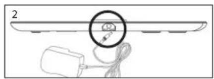
Connect the DC adapter to a suitable mains outlet and plug the small DC socket into the device.
Turn on the power the central display will light up orange and go off.
natural_image
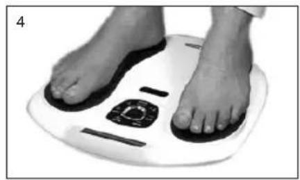
Close-up of a person's feet on a white foam roller with black foot markers (no text or symbols visible)Remove your footwear and socks or stockings. PLACE YOUR BARE FEET ONTO THE FOOT PADS. YOUR RIGHT FOOT ON THE RIGHT FOOT PAD AND YOUR LEFT FOOT ON THE LEFT FOOT PAD. BOTH FEET NEED TO BE ON THE DEVICE FOR IT TO WORK.
Sit in a comfortable chair. Place your bare feet on the left and right foot plates. Increase the intensity levels for the foot by pressing the "SOLE+" or to press "SOLE - " to decrease the intensity. The intensity level ranges from 0-99, slowly increase the level until you begin to feel the micro-current stimulation.
For a full explanation of setting the intensity, refer to page 14
IMPORTANT CUSTOMER INFORMATION
PLEASE READ:
Q: How do I use it?
A: Simply place your 'BARE FEET' ON THE FOOT PADS. The right foot on the right footpad and the left foot on the left footpad at the same time. The device will not work unless you have your soles on the foot pads.
Q: Does it vibrate?
A: No. This device DOES NOT VIBRATE. Circulator has been specifically designed to send tiny electrical impulses through the soles of your feet. This action causes your calf muscles to contract and release forcing the blood back up through the veins in your legs.
Q: I'm not feeling anything in my feet or legs?
A: Please note that the 'intensity' level goes all the way up to 99. The aim is not to get to 99, but to a level that suits you. This level may change on a daily basis.
Q: My feet are very dry and I'm not feeling the electrical impulses.
A: Remember to keep hydrated; drink plenty of fluids. Also, if you moisturise your feet, this will boost the health benefits.
Q: Is it difficult to use?
A: No. Simply place your bare feet onto the footpads, select the intensity setting and it automatically counts down from 30 minutes.
Q: Am I too old to get any benefit from it?
A: No. The product is suitable for any adult age.
Q: Can it really help me? I'm not very active and sit for most of the day.
A: Yes. As we sit, the blood naturally pools to the lower legs due to gravity, this is a natural action in the body. If we do not take frequent walks or exercise, the blood will pool and could cause your legs and feet issues such as swelling and poor blood circulation. Circulator may reduce these symptoms.
Q: My legs ache after using the device.
A: Either you had it on a SOLE setting that was too high for you (so reduce this setting next time you use it) or you have used it too many times within a few days. Just give your legs time to relax and then re-use the device.
WARNING
Should not be used by women in the first trimester of pregnancy, by people fitted with a pacemaker or other implanted medical device, or anyone being treated for existing deep vein thrombosis (DVT). Any questions, please call our Customer Service Number or consult your health professional.
IMPORTANT SAFETY INFORMATION
1) Please read these instructions thoroughly before use.
2) Please check that you have all of the component parts as detailed in this user manual.
3) Take all parts out of the plastic bags and examine them to familiarize yourself with the components.
Notes on safety
- The icons and warning signs are indicated here for your safety and correct usage of the product as well as to prevent injuries and/or damage to properties.
• The icons and meanings are as follows:
| Description of markings | |
 | The icon indicates prohibitions (must not do).Matters involving certain prohibitions are indicated by text or pictures in or near.The icon to the left means “Prohibitions to Disassemble”. |
 | The icon indicates something that is compulsory (must be observed).Matters involving certain compulsory actions are indicated by text or pictures in or near.The icon to the left refers to “General compulsory action”. |
 | This product should not be used by persons with medical implants, e.g. heart pacemakers, artificial heart, lung or other electronic life support systems. |
 | This symbol indicates that batteries must not be disposed of in the domestic waste as they contain substances which can be damaging to the environment and health. Please dispose of batteries in designated collection points. |
 | This marking indicates that this product should not be disposed with other household wastes throughout the EU. To prevent possible harm to the environment or human health from uncontrolled waste disposal, recycle it responsibly to promote the sustainable reuse of material resources. To return your used device, please use the return and collection systems or contact the retailer where the product was purchased. They can take this product for environmental safe recycling. |
 | Consult instructions for use. |
 | Date of manufacturers. |
 | Manufacturer's name. |
 | Batch Code. |
| [86XT] | Class II equipment |
| [YABD] | Caution, consult accompanying documents |
 | Type BF applied Part |
 | This symbol means serial number which is on the underside of the device and on the packaging. |
 | This symbol indicates that the unit meets the basic requirements set by the CE Directive 93/42/EEC concerning medical devices. |
| Danger | |
 | This unit must not be used in combination with the following medical devices:(1) Internally transplanted electronic medical devices, e.g. pacemakers(2) Electronic life support equipment, such as respirators(3) Electronic medical devices attached to the body, such as electrocardiographsUsing this unit with other electronic medical devices may cause erroneous operation of those devices. |
| Warning | |
 | The product should not be used during pregnancy, by people fitted with a pacemaker or other implanted medical device, or anyone being treated for Deep Vein Thrombosis (DVT). Not suitable for persons under 16 years of age. Persons with the following conditions must consult a doctor before using this unit:1) acute disease2) malignant tumor3) infectious disease4) cardiac dysfunction5) high fever6) abnormal blood pressure7) skin sensory disorders or skin problems8) receiving medical treatment, especially those feeling discomfort. May cause an accident or ill health. |
 | Do not use this unit near the heart, above the neck, on the head, around the mouth or on diseased skin.May cause an accident or ill health.- Application of electrodes between the neck and diaphragm (chest area) may increase the risk of cardiac fibrillation |
| Do not use this unit simultaneously with other therapeutic device or in combination with ointments including spray type ointments.May cause discomfort or ill health.- Simultaneous connection of a PATIENT to a h.f. surgical EQUIPMENT may result in burns at the site of the STIMULATOR electrodes and possible damage to the STIMULATOR.- Operation in close proximity (e.g. 1 m) to a shortwave or microwave therapy EQUIPMENT may produce instability in the STIMULATOR output. | |
| Do not use this unit for purposes other than treatment indicated in this manual.May lead to accident, problems, or failure of the unit. | |
| Do not insert the electrode cord plug into any place other than the electrode cord jack of the main unit.May cause an electric shock or accident. | |
 | Do not disassemble or remodel this unit.No user serviceable parts. |
| Caution | |
 | If the unit is not functioning properly or you feel discomfort, immediately stop using the unit.If you feel any problems with your body or skin, consult a doctor and follow his/her instructions. |
| If you want to move the Electrode Pad to another region or your body during treatment, be sure to turn off the power first.If not, you may receive a strong electrical shock. | |
| Do not try to attach the Pads to any other person during the treatment.You may receive strong electrical shock. | |
| Do not start treatment while wearing an electronic device.The settings and timings of the device may be affected. | |
 | Do not use this unit on infants or people not capable of expressing their intentions.May cause an accident or ill health. |
| Do not use this unit in places with high humidity such as bathrooms or while taking a bath or shower.You will receive a strong electrical shock. | |
| Do not use this unit while sleeping.The main unit may develop trouble, or the pad may move to an unexpected region and cause ill health. | |
| Do not use this unit while driving.Receiving sudden strong stimulation may lead to traffic accident. | |
| Do not leave the Electrode Pad attached to the skin after treatment.Pro longed attachment may cause skin irritation or infection. | |
| Be careful not to allow any metal object, such as a belt buckle or necklace to come into contact with the Electrode Pad during treatment.You may receive a strong electrical shock. | |
| Do not use cellular phones or other electronic devices near this unit. | |
| Put the Long Life pads only on skin or on the Long Life pads holder to avoid damage of the adhesive surfaces of the pads. | |
Important information regarding Electro Magnetic Compatibility
With the increased number of electronic devices such as PC's and mobile (cellular) telephones, medical devices in use may be susceptible to electromagnetic interference from other devices. Electromagnetic interference may result in incorrect operation of the medical device and create a potentially unsafe situation. Medical devices should also not interfere with other devices.
In order to regulate the requirements for EMC (Electro Magnetic Compatibility) with the aim to prevent unsafe product situations, the EN 60601-1-2 standard has been implemented. This standard defines the levels of immunity to electromagnetic interferences as well as maximum levels of electromagnetic emissions for medical devices.
This medical device manufactured by HoMedics conforms to this EN 60601-1-2 standard for both immunity and emissions. Nevertheless, special precautions need to be observed:
Do not use mobile (cellular) telephones and other devices, which generate strong electrical or electromagnetic fields, near the medical device. This may result in incorrect operation of the unit and create a potentially unsafe situation.
CB-200-EU needs special precautions regarding EMC and needs to be installed and put into service according to the EMC information provided in the ACCOMPANYING DOCUMENTS.
Portable and mobile RF communications equipment can affect CB-200-EU.
WARNING: the use of accessories, transducers and cables other than those supplied with the exception of the transducers and cables sold by the manufacturer of the CB-200-EU as replacement parts for internal components, may result in increased EMISSIONS or decreased IMMUNITY of CB-200-EU.
WARNING: the CB-200-EU should not be used adjacent to or stacked with other equipment.
Equipment not suitable for use in the presence of a flammable anaesthetic mixture with air or with oxygen or nitrous oxide.
WHAT IS ELECTRONIC NERVE STIMULATION?
INTENDED USE: Medical Purpose
This Electronic Nerve Stimulator is intended to be used as a massager to relieve (muscle) pain, increase blood circulation, relax stiff muscles, reduce swollen feet, ankles and fatigue in the feet/lower legs. The massaging effect is achieved by electronic stimulation of the nerves through electrode pads placed on the skin. Various massage regions and treatment programs can be selected.
Suitable Users: Please read "Notes on safety" before using the unit. (This unit should not be used by people prohibited from doing so in "Notes on safety".)
Environment: This unit is intended for home use only.
Effectiveness: Massager: relieve of (muscle) pain, stiffness and fatigue in the feet/lower legs.
Precautions for use: Please read "Notes on safety" before using the unit.
Electronic Nerve Stimulation is a non-invasive, safe nerve stimulation intended to reduce pain. The Circulatoruses proven neuromuscular electrical stimulation therapy to send micro current pulses through the soles of your feet. This type of electrical stimulation is clinically proven to be safe and effective and can be carried out in the comfort of your own home. The Circulator improves muscles function by stimulating nerves increasing the flow of blood helping to reduce PAIN, SWELLING, TIRED AND ACHING LEGS.
MACHINE OVERVIEW AND PART NAMES
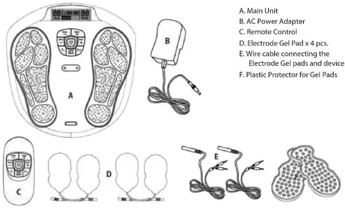
A. Main Unit
B. AC Power Adapter
C. Remote Control
D. Electrode Gel Pad x 4 pcs.
E. Wire cable connecting the Electrode Gel pads and device
F. Plastic Protector for Gel Pads

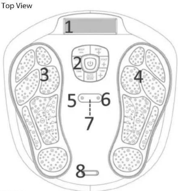
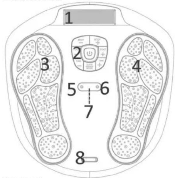
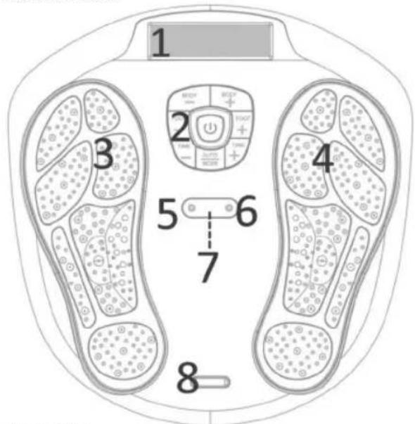
Side View

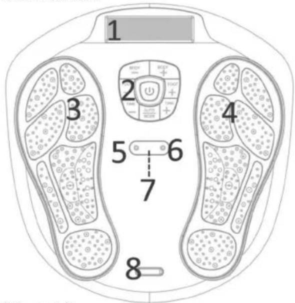
- LCD Display Screen
- Control Panel
- Electrode Area for Left Foot
- Electrode Area for Right Foot
- Cable Connecting the Electrode Gel Pads and Device.
- Cable Connecting the Electrode Gel Pads and Device.
- Remote Control Receiver Sensor
- Silver colour decoration plate
- Adaptor Jack
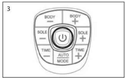
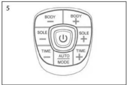
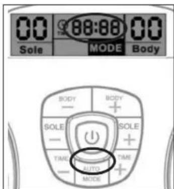
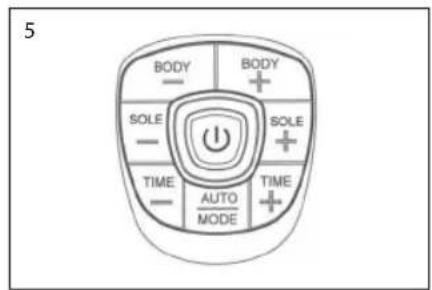
FUNCTION OF CONTROL PANEL
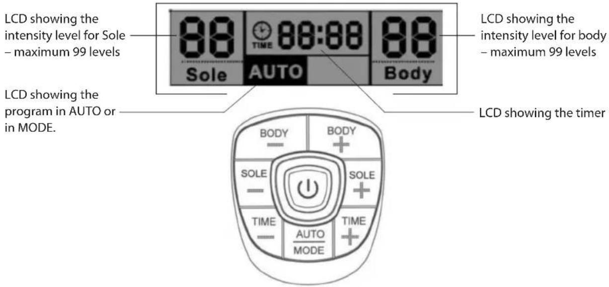
| ON/OFF switch button | |
| BODY – Decrease the output intensity of body (Available from 1 - 99 levels) | |
| BODY + Increase the output intensity of body (Available from 1 - 99 levels) | |
| SOLE - Decrease the output intensity of Sole (Available from 1 - 99 levels) | |
| SOLE + Increase the output intensity of sole (Available from 1 - 99 levels) | |
| TIME - Decrease the operation time (available from 1-60 minutes) | |
| TIME + Increase the operation time (available from 1-60 minutes) | |
| AUTO/MODE | Auto - the preset program with 14 pattern in cycle running for Foot and 10 pattern in cycle running for bodyMode - user can fix the program to the exiting massage pattern on the rest of the time |
Electrode area of the unit and the gel pad

natural_image
Diagram of a human footset with circular patterns and control panel (no text or labels)Fig. A
On the device the black colour area on the device which is the electrode area for the sole. (see. the fig. A).
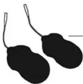
natural_image
Silhouette of two black oval objects with loop handles, resembling stylized menses or gloves (no text or symbols)Fig. B
On the gel pad, the black colour area on the sticky part is the electrode area for the body, size is 5 cm x 9 cm. (see. the fig. B)
CIRCULATOR OUTPUT WAVE FORMS
FOOT ELECTRO THERAPY MASSAGE: We will examine the operation in more detail later in your instructions but the principle is relatively easy to understand. Place your feet on the electrode areas, turn on Circulator with the central on/off switch, then increase the intensity for the foot. There are 99 different levels. When you start to feel the mild electro-therapy will depend on your own nerve sensitivity. Certain individuals will feel nothing until the intensity is up at a high level, others will feel the stimulation at relatively low levels. This is completely normal.
BODY PAIN RELIEF: If you choose to target pain in other areas of your body the Circulator comes with four gel pads. These can be used to treat arms, hips, thighs, abs or buttocks or target neck muscle or back pain.
OUTPUT WAVEFORM
***THE OUTPUTS HAVE NO DC COMPONENT
SOLE MASSAGER (during 1 kΩ load)
The auto mode will cycle through the 14 programs during the units operation, repeating automatically.
| Programme | Output |
| 1 | Pulse rate 12.2Hz with 8.5 seconds and off time in 900mS, A cycle repeating for 1 minute |
| 2 | Pulse rate 16.13Hz with 2.8 seconds and off time in 900mS, A cycle repeating for 1 minute |
| 3 | Pulse rate 20.0Hz with 8.4 seconds and off time in 900mS, A cycle repeating for 1 minute |
| 4 | Pulse rate 16.13Hz with 5.8 seconds and off time in 900mS, A cycle repeating for 1 minute |
| 5 | Pulse rate 16.16Hz with 7.0 seconds and off time in 900mS, A cycle repeating for 1 minute |
| 6 | Pulse rate 33.33Hz with 2.3 seconds and off time in 900mS, A cycle repeating for 1 minute |
| 7 | Pulse rate 12.50Hz with 4.6 seconds and off time in 900mS, A cycle repeating for 1 minute |
| 8 | Pulse rate 55.56Hz with 11.5 seconds and off time in 900mS, A cycle repeating for 1 minute |
| 9 | Pulse rate 23.32Hz with 5.6 seconds and off time in 900mS, A cycle repeating for 1 minute |
| 10 | Pulse rate 20.0Hz with 4.5 seconds and off time in 900mS, A cycle repeating for 1 minute |
| 11 | Pulse rate 10Hz with 5.3 seconds and off time in 900mS, A cycle repeating for 1 minute |
| 12 | Pulse rate 16.13Hz with 5.60 seconds and off time in 900mS, A cycle repeating for 1 minute |
| 13 | Pulse rate 26.32Hz with 3.5 seconds and off time in 900mS, A cycle repeating for 1 minute |
| 14 | Pulse rate 25Hz with 7.0 seconds and off time in 900mS, A cycle repeating for 1 minute |
BODY MASSAGER (during 1 kΩ load)
During the operation, the unit will cycle through the 10 programs, repeating automatically.
| Programme | Output |
| 1 | Pulse rate 25.00Hz with 5.8 seconds and off time in 900mS, A cycle repeating for 1 minute |
| 2 | Pulse rate 16.67Hz with 11.6 seconds and off time in 900mS, A cycle repeating for 1 minute |
| 3 | Pulse rate 12.5hz 9.7 seconds and off time in 900mS, A cycle repeating for 1 minute |
| 4 | Pulse rate 12.50Hz with 4.4 seconds and off time in 900mS, A cycle repeating for 1 minute |
| 5 | Pulse rate 25.00Hz with 13 seconds and off time in 900mS, A cycle repeating for 1 minute |
| 6 | Pulse rate 16.67Hz with 10.2 seconds and off time in 900mS, A cycle repeating for 1 minute |
| 7 | Pulse rate 12.5Hz with 5.6 seconds and off time in 900mS, A cycle repeating for 1 minute |
| 8 | Pulse rate 12.5Hz with 18.2 seconds and off time in 900mS, A cycle repeating for 1 minute |
| 9 | Pulse rate 16.67Hz with 5.1 seconds and off time in 900mS, A cycle repeating for 1 minute |
| 10 | Pulse rate 10Hz with 21.8 seconds and off time in 900mS, A cycle repeating for 1 minute |
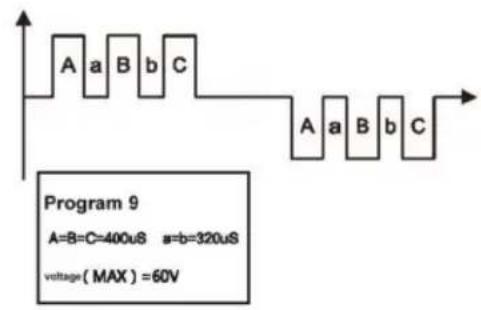
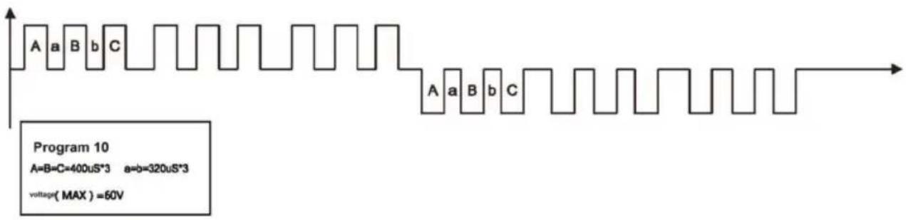
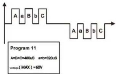
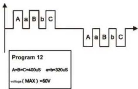
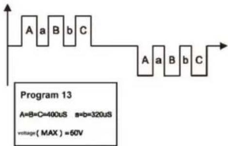
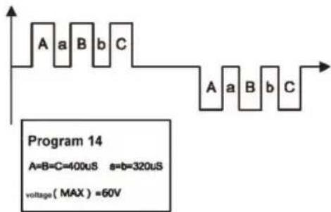
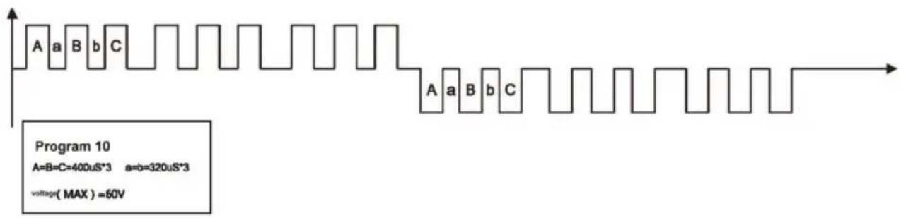
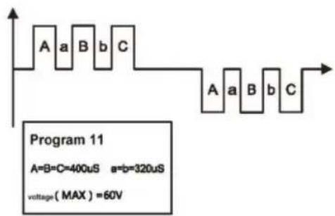
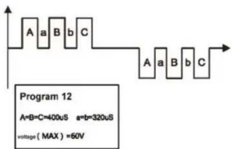
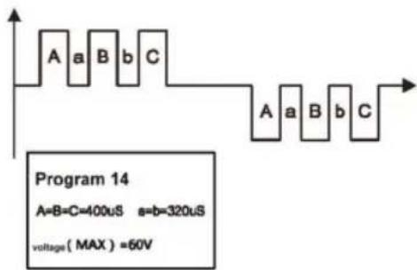
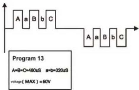
Foot Massager EMS Waveform and Pulse Width Diagram below:
During 1kΩ load connected with the sole electrode part.
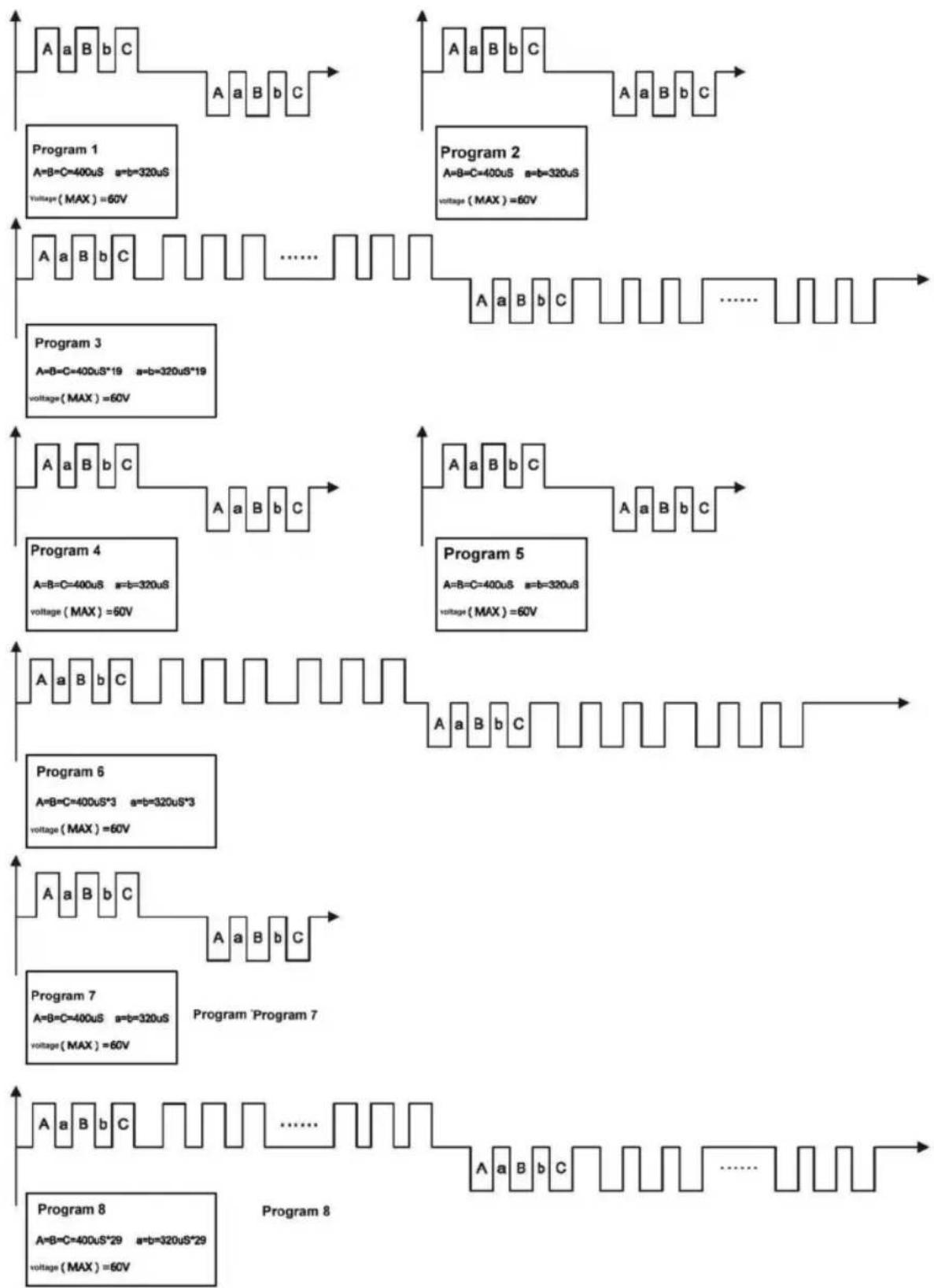
flowchart
graph TD
    subgraph Program 1
        A1["A=B=C=400uS a=b=320uS\nVoltage(MAX)=60V"] --> B1["B"]
        B1 --> C1["C"]
        C1 --> D1["A"]
    end
    subgraph Program 2
        A2["A=B=C=400uS a=b=320uS\nVoltage(MAX)=60V"] --> B2["B"]
        B2 --> C2["C"]
        C2 --> D2["A"]
    end
    subgraph Program 3
        A3["A=B=C=400uS*19 a=b=320uS*19\nVoltage(MAX)=60V"] --> B3["B"]
        B3 --> C3["C"]
        C3 --> D3["......"]
    end
    subgraph Program 4
        A4["A=B=C=400uS a=b=320uS\nVoltage(MAX)=60V"] --> B4["B"]
        B4 --> C4["C"]
        C4 --> D4["A"]
    end
    subgraph Program 5
        A5["A=B=C=400uS a=b=320uS\nVoltage(MAX)=60V"] --> B5["B"]
        B5 --> C5["C"]
        C5 --> D5["......"]
    end
    subgraph Program 6
        A6["A=B=C=400uS*3 a=b=320uS*3\nVoltage(MAX)=60V"] --> B6["B"]
        B6 --> C6["C"]
        C6 --> D6["......"]
    end
    subgraph Program 7
        A7["A=B=C=400uS a=b=320uS\nVoltage(MAX)=60V"] --> B7["B"]
        B7 --> C7["C"]
        C7 --> D7["......"]
    end
    subgraph Program 8
        A8["A=B=C=400uS*29 a=b=320uS*29\nVoltage(MAX)=60V"] --> B8["B"]
        B8 --> C8["C"]
        C8 --> D8["......"]
    end
BODY MASSAGER EMS Waveform and pulse width diagram below.
During 1kΩ load connected with the body electrode part

flowchart
graph TD
    subgraph Program 1
        A1["A=B=C=400uS a=b=320uS\nVoltage(MAX)=55V"] --> B1["Waveform"]
        B1 --> C1["Program 1"]
        C1 --> D1["Waveform"]
        D1 --> E1["Program 2"]
        E1 --> F1["Waveform"]
        F1 --> G1["Program 3"]
        G1 --> H1["Waveform"]
        H1 --> I1["Program 4"]
        I1 --> J1["Waveform"]
        J1 --> K1["Program 5"]
        K1 --> L1["Waveform"]
        L1 --> M1["Program 6"]
        M1 --> N1["Waveform"]
        N1 --> O1["Program 7"]
        O1 --> P1["Waveform"]
        P1 --> Q1["Program 8"]
        Q1 --> R1["Waveform"]
        R1 --> S1["Program 9"]
        S1 --> T1["Waveform"]
    end
    subgraph Program 2
        A2["A=B=C=400uS a=b=320uS\nVoltage(MAX)=55V"] --> B2["Waveform"]
        B2 --> C2["Program 2"]
        C2 --> D2["Program 3"]
        D2 --> E2["Program 4"]
        E2 --> F2["Program 5"]
        F2 --> G2["Program 6"]
        G2 --> H2["Program 7"]
        H2 --> I2["Program 8"]
        I2 --> J2["Program 9"]
        J2 --> K2["Program 10"]
    end
    subgraph Program 3
        A3["A=B=C=400uS a=b=320uS\nVoltage(MAX)=55V"] --> B3["Waveform"]
        B3 --> C3["Program 3"]
        C3 --> D3["Program 4"]
        D3 --> E3["Program 5"]
        E3 --> F3["Program 6"]
        F3 --> G3["Program 7"]
        G3 --> H3["Program 8"]
        H3 --> I3["Program 9"]
    end
    subgraph Program 4
        A4["A=B=C=400uS a=b=320uS\nVoltage(MAX)=55V"] --> B4["Waveform"]
        B4 --> C4["Program 4"]
        C4 --> D4["Program 5"]
        D4 --> E4["Program 6"]
        E4 --> F4["Program 7"]
        F4 --> G4["Program 8"]
        G4 --> H4["Program 9"]
    end
    subgraph Program 5
        A5["A=B=C=400uS a=b=320uS\nVoltage(MAX)=55V"] --> B5["Waveform"]
        B5 --> C5["Program 5"]
        C5 --> D5["Program 6"]
        D5 --> E5["Program 7"]
        E5 --> F5["Program 8"]
    end
    subgraph Program 6
        A6["A=B=C=400uS a=b=320uS\nVoltage(MAX)=55V"] --> B6["Waveform"]
        B6 --> C6["Program 6"]
        C6 --> D6["Program 7"]
        D6 --> E6["Program 8"]
    end
HOW TO OPERATE
For Feet - SOLE
- Place your bare feet onto Circulator(do not wear socks).
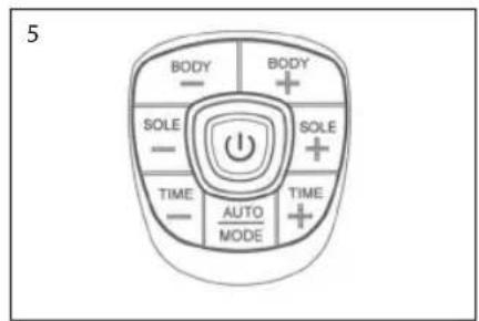
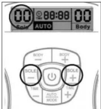
- Press the on/off button, the LCD screen will light up in Orange. And the program show AUTO and both Band shown in 00, which is in standby mode (see Fig. 1).
- Gently increase intensity setting by pushing the button of "SOLE +". Or decrease intensity setting by pushing the button of "SOLE -". The intensity level is adjustable between 0 and 99. The LCD display will show the selected level (see Fig. 2).
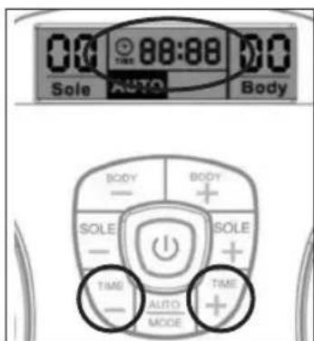
- You can adjust the auto off timer by pressing the "Time -" or "Time +". Timer range from 1-60 minutes. The timer will begin to count down from the time setting you select (see Fig. 3). To terminate the massage period, user can turn off the unit anytime by pressing the on/off button once.
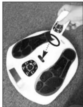
- If you are satisfied with the current massage programme, you can lock the current massage programme by pressing the Auto/Mode key. The rest of the massage time will then only run the selected massage programme (see Fig. 4).
IMPORTANT INFORMATION:
a. The aim is not to get up to level '99'.
b Chose an intensity level that is comfortable for you! This level may vary from day to day.
c. Remember to drink plenty of fluid – if you are dehydrated, this will reduce the effectiveness of the device.
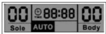
Fig. 1

Fig. 2

Fig. 3

Fig. 4
For Body
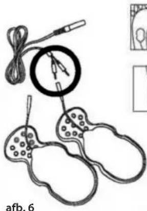
USING THE GEL PADS
Wash and dry skin before use. Connect the output wire to the gel pads. Connect the other end of the output wire to the output jack on Circulator. Remove the protective film from the adhesive pads. Attach the gel pads to the skin. Press the on/off button to turn on the unit and adjust the stimulating output intensity to the desired level. (The display will show the mode and level that you selected and start to count down).
natural_image
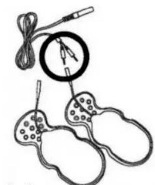
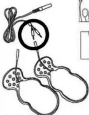
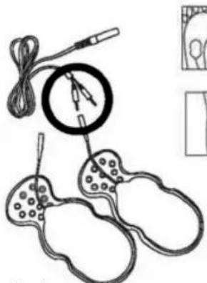
Illustration of a medical or scientific setup with coiled wires, a magnified circular component, and three separate ear-shaped devices (no text or symbols)Fig. 6
natural_image
Six-panel line drawing showing foot, torso, and leg views (no text or symbols)
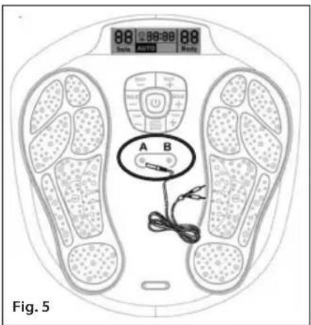
- Plug in the 2 cables into the cable jack on the unit (see Fig. 5).
- Connect pin of the cable to the gel pad properly (see Fig.6).
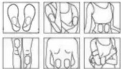
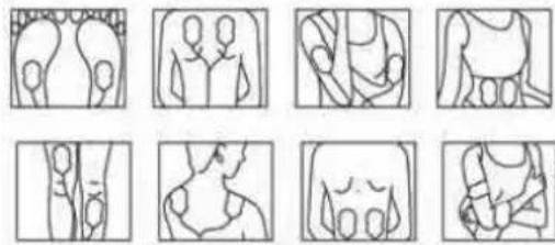
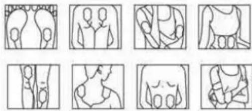
- Remove the protective film on the gel pad, and attached the 4 gel pads to the area of the body you wish to treat in accordance with warnings.
- Repeat operation as in foot instructions, adjust the intensity using for body.
- Gently increase intensity setting by pushing the button of "Body +". Or decrease intensity setting by pushing the button of "Body -". The LCD will also show the level which you have selected (see Fig. 7).
- To terminate the massage period, user can turn off the unit anytime by pressing the on/off button. If you want to use 2 gel pads only, then you must connect 1 gel pad to jack A and 1 gel pad to Jack B.
ADDITIONAL ACCESSORIES
Replacement gel pads
For information on how to buy replacement gel pads, please visit www.homedics.co.uk
natural_image
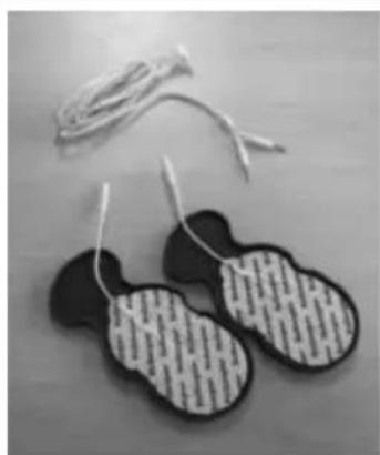
Pair of black and white patterned electronic circuit boards on a wooden surface (no text or symbols visible)Care of your gel pads
Never stick two adhesive pads to each other. Keep the adhesive gel pads clean, never expose them to high temperature or direct sunlight. If the electrode gel pads are insufficiently adhesive or dirty, wipe with a wet cloth or change for new ones, replacement parts will be available directly from HoMedics or your distributor.
Do not clean the electrode gel pads with any chemical.
ALWAYS try and protect the gel pads. Store the gel pads on the gel pad protector when not in use, as in the illustration.
CONNECT WITH THE SUPPLIED AC/DC POWER ADAPTER
natural_image
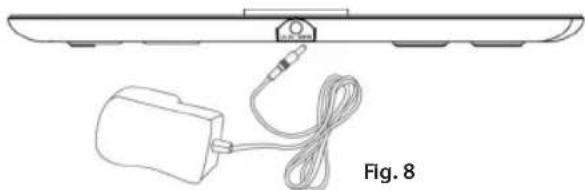
Diagram of a device with cable and plug, labeled Fig. 8 (no text or symbols on the diagram itself)Plug the DC plug of the power supply into the socket on the side of Circulator. (See Fig 8) Plug in power adapter to a suitable wall socket. (Make sure that the input voltage of the wall socket is suitable for the supplied adapter.)
INSTALLING BATTERIES FOR MAIN UNIT
If you want to use the Circulator with battery power instead of the supplied main adapter, the battery compartment is located on the underside of the unit.
Remove the battery cover from the unit by removing the screw with a screwdriver. Insert the new 4 pieces 1.5V size AA batteries with the + and - marks correctly aligned.
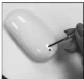
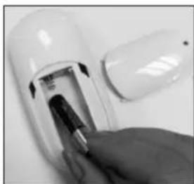
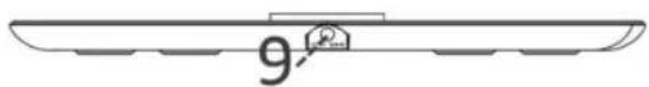
INSTALLING BATTERIES FOR REMOTE CONTROL
Remove the battery cover from the unit by removing the screw with the screwdriver. Insert the new 2 pieces 1.5V size AAA batteries with the + and - marks correctly aligned.
natural_image
Close-up of a hand using a screwdriver to apply a small white object on a plain surface (no text or symbols visible)
natural_image
Close-up of a hand inserting a plug into a white cylindrical device (no visible text or symbols)
natural_image
Close-up of a white handheld device with black control panel (no visible text or symbols)The transmitter of the remote control is at the top of it in black colour (Fig. 10), for using the remote control, please remember to point the transmitter to the receiver of the main unit, which is located at between the gel pad jack of the main unit. (Fig. 11).
natural_image
Top-down view of a white foot with black shoes and control buttons, being handled by a hand (no text or symbols visible)Fig. 11
Note on batteries:
Do not mix different types of batteries or old batteries with new ones. To prevent the risk of leakage or explosions, never recharge the batteries, apply heat or take them apart.
When not using batteries, remove them to prevent battery drain. If liquid leaks from the batteries, throw them away. See page 4 for correct disposal. Thoroughly clean the battery compartment with a dry cloth.
CLEANING

Electrode Gel pad
- When not in use, store the Electrode Gel pads on the plastic pad protectors provided at room temperature.
- Keep the Electrode Gel pads clean and dust free in a dry location, keep away from oily or sticky location. Otherwise the life of the electrodes varies depending on skin conditions, storage, amount of use, type of stimulation, and stimulation site. Usage may be extended by carefully cleaning the gel surface with water. Do not spill liquid on the wire.
- Single patient use only.
- Do not apply to cracked skin. Should a skin rash occur, discontinue use and contact your physician
- Do not use tissue, cloth etc. to wipe the electrode surface.
- Do not use finger nails, brushes etc. against the electrode surface as it might damage.
- Do not clean the pads too often, and don't use the detergent or hot water to clean the electrode gel pads

Main Device
- Switch off the power and remove the adapter and the electrode gel pad from the unit for storage in correct way.
• Always keep the main device clean by using a soft cloth to clean the surface of the unit.
• To clean the foot pedals, use a soft, damp, soapy cloth but make sure you squeeze the cloth dry and clean the foot pedal area. - If the device is very dirty, use a soft, damp, soapy cloth, but make sure you squeeze the cloth dry before cleaning the unit.
- Do not spill liquid on the device
- Do not immerse the device in water
- Do not clean with chemicals
- Store in a dry, dust free location in temperature between 10 to 40^ and 30% to 90% relative humidity.

Safety Precautions
- Do not open the device or repair it yourself. This will invalidate your warranty and may cause serious harm.
- If the device malfunctions, disconnect it from the power source and contact your selling agent as soon as possible.
- Use only the accessories supplied by the manufacturer.
- Use the device only for its intended purpose.
- Do not expose the device to extreme heat.
- Do not overload the electrical outlet.
- Do not stand on the machine. Use it when sitting down only.
- Do not spill liquid on the device or its accessories
The warranty is void if the product has been altered, misused or abused. HoMedics will not take any responsibility.
TROUBLESHOOTING & MAINTENANCE
| Problem | Cause | Rectification |
| Device will not turn on. | - Batteries inserted in wrong direction.- The adapter does not plug well into device properly. | - Insert batteries in correct direction or check the battery is in full power.- Check the connection of the adapter jack is in well connected. And also the DC adapter with well connecting to the main socket. |
| Power turns off too soon | - Gel pads not attached correctly to the skin. - Attach Gel pads correctly to the skin | |
| Power turns off while using massager | - If you are using the batteries operation, then the batteries might be weak/exhausted | - Fit 4 new identical 1.5V alkaline batteries type AA |
| - The 30 minute timer is included as this is the recommended maximum treatment time | - It is possible to simply restart the treatment if required (for a second user for example) | |
| - If you are using the body massage, the electrode gel pad may be broken | -Replace electrode gel pad | |
| It is difficult to attach Gel pad to the skin | - Transparent film not peeled off- Gel pad applied immediately after washing- Adhesive surface of Gel pad damaged- The gel pads got dirty and lost their adhesive/stickiness | - Peel off film on the adhesive surface of Gel pad- Sufficiently dry Gel pad- Replace Gel pad- Replace Gel pad or clean the gel pad with a small drop of water onto the sticky side of the electrode pad and rub into the surface |
| Adhesive surface of Gel pad is not sticky | - Use of Gel pad whilst perspiring- Gel pad washed too long and/or too frequently- Gel pads stored under high temperature, high humidity, direct sunlight | - Leave Gel pad in freezer for overnight |
| It is difficult to feel stimulation | - You sole is too dry, not enough moisture- Your sole is not placing on the foot pedal properly- Gel pads not attached correctly to the skin- Gel pads overlap each other- Electrode cord not connected correctly- Applied intensity too weak | - Put some water on your sole to moisturise your sole- Ensure both of your soles are placed on each pedal properly.- Attach Gel pad firmly to the skin- Reattach Long Life pads with no overlap- Connect electrode cord correctly- Increase the intensity by pressing the + button. |
| The skin turns red or the skin feels irritated | - Adhesive surface of Gel pads dirty or dry- Adhesive surface of Gel pads damaged | - Wash adhesive surface of Gel pads softly with your fingertips for about 3 seconds under slow running water- Replace Gel pads |
Hygiene
After using the product
Clean the device with a soft, damp cloth, but make sure you squeeze the cloth dry before cleaning the foot pedal area.
Store the Electrode Gel pads on the plastic pad protectors provided.
Storage
Keep the whole set of product clean and store in a dust free and dry location.
Storage temperature and humidity -10°C to 60°C, 10% to 95% RH
Operating temperature and humidity -5°C to 50°C, 30% to 90% RH
TECHNICAL SPECIFICATIONS
| Product Name Circulator | |
| Model CB-200-EU | |
| Power supply | 6V DC or 4x1.5V alkaline batteries type AA* for the main unit 2x1.5V alkaline batteries type AAA* for the remote control |
| Supplier of Adapter | Golden Profit Electronics Ltd. |
| Model no. of Adapter | GPE038-060050-3 |
| Adapter Input | AC 100-240V~50-60Hz 0.1A |
| Adapter Output DC 6V 500mA 3.0W | |
| Battery life >350 minutes | |
| Frequency generation Approx. 10 Hz to 55.56 Hz | |
| Power consumption 1.05 W | |
| Maximum Output Voltage U <54.8V (during 1 kΩ load) | |
| Maximum Output Current I < 910 μA (during 1 kΩ load) | |
| Operating temperature and humidity -5°C to 50°C | 30% to 90% RH |
| Storage temperature and humidity -10°C to 60°C, | 10% to 95% RH |
| Main unit dimensions 338(L) x 324 (W) x 48(H) mm | |
| Weight Approx. 950 g | |
| Package Contents | Quantity Parts1 Circulator1 AC/DC Adapter1 Remote Control2 Cable Wire for Electrode Gel pads4 Electrode Gel pads2 Plastic Gel pads protector1 Instruction manualAccessories:Only use original accessories.Check that the contents of the delivery are complete. |
* batteries not included.
IMPORTANT INFORMATION
Electro Magnetic Compatibility (EMC)
- Circulator needs special precautions regarding EMC and needs to be installed and put into service according to the EMC information provided in the ACCOMPANYING DOCUMENTS;
- Portable and mobile RF communications equipment can affect Circulator.
- Warning: the use of accessories, transducers and cables other than those specified with the exception of transducers and cables sold by the manufacturer of the Circulator as replacement parts for internal components, may result in increased EMISSIONS or decreased IMMUNITY of the Circulator.
- Warning: the Circulator should not be used adjacent to or stacked with other equipment.
| Guidance and manufacturer's declaration – electromagnetic emissions | ||
| The Circulator is intended for use in the electromagnetic environment specified below. The customer or the user of the Circulator should assure that it is used in such an environment. | ||
| Emission test Compliance | Electromagnetic environment – guidance | |
| RF emissionsCISPR 11 | Group 1 | The Circulator uses RF energy only for its internal function. Therefore, its RF emissions are very low and are not likely to cause any interference in nearby electronic equipment. |
| RF emissionsCISPR 11 | Class B | The Circulator is suitable for use in all establishments, including domestic establishments and those directly connected to the public low-voltage power supply network that supplies buildings used for domestic purposes. |
| Harmonic emissionsIEC 61000-3-2 | Class A | |
| Voltage fluctuations/flicker emissionsIEC 61000-3-3 | Complies | |
| Guidance and manufacturer's declaration - Electromagnetic Immunity | |||
| The Circulator is intended for use in the electromagnetic environment specified below. The customer or the user of the Circulator should assure that it is used in such an environment. | |||
| Immunity test | IEC 60601 test level | Compliance level E | Electromagnetic environment - guidance |
| Electrostatic discharge (ESD) IEC 61000-4-2 | ±6 kV contact ±8 kV air | ±6 kV contact ±8 kV air | Floors should be wood, concrete or ceramic tile. If the floor is covered with synthetic material, the relative humidity should be at least 30%. |
| Electrical fast transient/burst IEC 61000-4-4 | ±2 kV for power supply lines ±1kV for input/output lines | ±2 kV for power supply lines ±1kV for input/output lines | Mains power quality should be that of a typical commercial or hospital environment. |
| Surge IEC 61000-4-5 | ±1 kV line(s) and neutral | ±1 kV line(s) and neutral | Mains power quality should be that of a typical commercial or hospital environment. |
| Voltage dips, short interruptions and voltage variations on power supply input lines IEC 61000-4-11 | <5% UT (>95% dip in UT) for 0.5 cycle | <5% UT (>95% dip in UT) for 0.5 cycle | Mains power quality should be that of a typical commercial or hospital environment. If a dips or an interruption of mains power occurs, the current of the Circulator may be dropped off from normal level, it may be necessary to use uninterruptible power supply or a battery. |
| 40% UT (60% dip in UT) for 5 cycles | 40% UT (60% dip in UT) for 5 cycles | ||
| 70% UT (30% dip in UT) for 25 cycles | 70% UT (30% dip in UT) for 25 cycles | ||
| <5% UT (>95% dip in UT) for 5 sec | <5% UT (>95% dip in UT) for 5 sec | ||
| Power frequency (50Hz) magnetic field IEC61000-4-8 | 3A/m Not applicable | Not applicable | |
| NOTE: UT is the a.c. mains voltage prior to application of the test level. | |||
| Guidance and manufacture's declaration - electromagnetic immunity | |||
| The Circulator is intended for use in the electromagnetic environment specified below. The customer or the user should assure that it is used in such an environment. | |||
| Immunity test | IEC 6 0601 test level | Compliance level | Electromagnetic environment - guidance |
| Conducted RFIEC 61000-4-6 | 3 V/ms150 kHz to 80 MHz | 3 V/ms | Portable and mobile RF communications equipment should be used no c bser to any part of the ELECTRO FLEX, including cables, than the recommended separation distance calculated from the equation applicable to the frequency of the transmitter. |
| Radiated RFIEC 61000-4-3 | 3 V/m26 MHz to 2.5 GHz | 3 V/m | Recommended separation distance d=1,2 d=1,2 80 MHz to 800 MHz d=2,3 800 MHz to 2.5 GHzwhere P is the maximum output power rating of the transmitter in watts (W) according to the transmitter manufacturer and d is the recommend ed separation distance in metres (m).Field strengths from fixed RF transmitters, as determined by an electromagnetic site survey, a should be less than the compliance level in each frequency range b.Interference may occur in the vicinity of equipment marked with the following symbol: |
| 10 V/m26 MHz to 2.5 GHz | 10 V/m | ||
| NOTE 1 At 80 MHz and 800 MHz, the higher frequency range applies.NOTE 2 These guidelines may not apply in all situations. Electromagnetic propagation is affected by absorption and reflection from structures, objects and people. | |||
| a Field strengths from fixed transmitters, such as base stations for radio (cellular/cordless) telephones and land mobile radios, amateur radio, AM and FM radio broadcast and TV broadcast cannot be predicted theoretically with accuracy.To assess the electromagnetic environment due to fixed RF transmitters, an electromagnetic site survey should be considered. If the measured field strength in the location in which the Circulator is used exceeds the applicable RF compliance level above, the Circulator should be observed to verify normal operation. If abnormal performance is observed, additional measures may be necessary, such as reorienting or relocating the Circulator.b Over the frequency range 150 kHz to 80 MHz, field strengths should be less than 3 V/m. | |||
7.
| Recommended separation distances between portable and mobile RF communications equipment and the Circulator | |||
| The Circulator is intended for use in an electromagnetic environment in which radiated RF disturbances are controlled. The customer or the user of the Circulator can help prevent electromagnetic interference by maintaining a minimum distance between portable and mobile RF communications equipment (transmitters) and the Circulator as recommended below, according to the maximum output power of the communications equipment. | |||
| Rated maximum output power of transmitter W | Separation distance according to frequency of transmitter m | ||
| 150 kHz to 80 MHz d = 1,2 | 80 MHz to 800 MHz d = 1,2 | 800 MHz to 2,5 GHz d = 2,3 | |
| 0,01 0.12 0.12 0.23 | |||
| 0,1 0.38 0.38 0.73 | |||
| 1 1.2 1.2 2.3 | |||
| 10 3.8 3.8 7.3 | |||
| 100 12 12 23 | |||
| For transmitters rated at a maximum output power not listed above, the recommended separation distance d in meters (m) can be estimated using the equation applicable to the frequency of the transmitter, where P is the maximum output power rating of the transmitter in watts (W) according to the transmitter manufacturer.NOTE 1 At 80 MHz and 800 MHz, the separation distance for the higher frequency range applies.NOTE 2 These guidelines may not apply in all situations. Electromagnetic propagation is affected by absorption and reflection from structures, objects and people. | |||
GUIDE DE RAPIDE
natural_image
Close-up of a person's feet on a white foam roller with black footprints and circular buttons (no text or symbols visible)Retirez vos chaussures et chaussettes ou bas. PLACEZ VOS PIEDS NUS SUR LES PLATEAUX. VOTRE PIED DROIT SUR LE PLATEAU DE DROITE ET VOTRE PIED GAUCHE SUR LE PLATEAU DE GAUCHE. LES DEUX PIEDS DOIVENT ÊTRE BIEN POSÉS SUR L'APPAREIL POUR PROFITER DE SES BIENFAITS.

Vue du dessus

Vue du dessous
natural_image
Diagram of a human footset with circular patterns and control panel (no text or labels)Sch. A
natural_image
Silhouette of two black, rounded objects with loop handles, resembling stylized smiley or abstract shapes (no text or symbols)Sch. B


flowchart
graph TD
    subgraph Program 1
        A1["A=B=C=400uS a=b=320uS\nVoltage(MAX)=55V"] --> B1["Waveform with alternating blocks"]
        B1 --> C1["Output"]
    end
    subgraph Program 2
        A2["A=B=C=400uS a=b=320uS\nVoltage(MAX)=55V"] --> B2["Waveform with alternating blocks"]
        B2 --> C2["Output"]
    end
    subgraph Program 3
        A3["A=B=C=400uS a=b=320uS\nVoltage(MAX)=55V"] --> B3["Waveform with alternating blocks"]
        B3 --> C3["Output"]
    end
    subgraph Program 4
        A4["A=B=C=400uS a=b=320uS\nVoltage(MAX)=55V"] --> B4["Waveform with alternating blocks"]
        B4 --> C4["Output"]
    end
    subgraph Program 5
        A5["A=B=C=400uS a=b=320uS\nVoltage(MAX)=55V"] --> B5["Waveform with alternating blocks"]
        B5 --> C5["Output"]
    end
    subgraph Program 6
        A6["A=B=C=400uS a=b=320uS\nVoltage(MAX)=55V"] --> B6["Waveform with alternating blocks"]
        B6 --> C6["Output"]
    end
    subgraph Program 7
        A7["A=B=C=400uS a=b=320uS\nVoltage(MAX)=55V"] --> B7["Waveform with alternating blocks"]
        B7 --> C7["Output"]
    end
    subgraph Program 8
        A8["A=B=C=400uS a=b=320uS\nVoltage(MAX)=55V"] --> B8["Waveform with alternating blocks"]
        B8 --> C8["Output"]
    end
    subgraph Program 9
        A9["A=B=C=400uS a=b=320uS\nVoltage(MAX)=55V"] --> B9["Waveform with alternating blocks"]
        B9 --> C9["Output"]
    end
COMMENT L'UTILISER

natural_image
Eight sequential line drawings of human body parts, showing progressive stages from left to right (no text or symbols)natural_image
Pair of black-and-white striped electronic devices with wires attached (no text or symbols visible)natural_image
Diagram of a cable and plug assembly with a labeled section 'Sch. 8' (no text or symbols on the diagram itself)natural_image
Close-up of a hand using a screwdriver to apply a small dot on a white computer mouse (no text or symbols visible)Sch. 8 Sch. 9 Sch. 10
natural_image
Close-up of a hand inserting a small electronic device into a white cylindrical device (no visible text or symbols)
natural_image
Close-up of a white handheld device with black control panel (no visible text or symbols)natural_image
Close-up of a foot massage device with black buttons and a hand adjusting the pad (no visible text or symbols)Sch. 11
natural_image
Close-up of a person's feet on a white foam roller with black footprints (no text or symbols visible)
Ansicht von oben
Seitenansicht
natural_image
Front view of a medical or electronic device with four foot-shaped foot patterns and a central control panel (no text or symbols)Abb. A
natural_image
Silhouette of two black, oval-shaped objects with loop handles, resembling stylized smiley or abstract shapes (no text or symbols)Abb. B


The image is too blurry to recognize any text content.
$$ A = B = C = 4 0 0 \mu S \quad a = b = 3 2 0 \mu S $$
$$ \text { Voltage } (\text { MAX }) = 5 5 \mathrm{V} $$
$$ A = B = C = 4 0 0 \mu S \quad s = b = 3 2 0 \mu S $$
$$ \text { Voltage } (\text { MAX }) = 5 5 \mathrm{V} $$
$$ A = B = C = 4 0 0 u S \quad a = b = 3 2 0 u S $$
$$ \text { Voltage } (\text { MAX }) = 5 5 \mathrm{V} $$
$$ A = B = C = 4 0 0 \mu S \quad a = b = 3 2 0 \mu S $$
$$ \text { Voltage } (\text { MAX }) = 5 5 \mathrm{V} $$
$$ A = B = C = 4 0 0 \mu S \quad a = b = 3 2 0 \mu S $$
$$ \text { Voltage } (\text { MAX }) = 5 5 \mathrm{V} $$
$$ A = B = C = 4 0 0 \mu S \quad a = b = 3 2 0 \mu S $$
$$ \text { Voltage } (\text { MAX }) = 5 \text { SV } $$
$$ A = B = C = 4 0 0 u S \quad a = b = 3 2 0 u S $$
$$ \text { Voltage } (\text { MAX }) = 5 5 \mathrm{V} $$
$$ A = B = C = 4 0 0 u S \quad a = b = 3 2 0 u S $$
$$ \text { Voltage } (\text { MAX }) = 5 5 \mathrm{V} $$
$$ A = B = C = 4 0 0 \mathrm{uS} \quad a = b = 3 2 0 \mathrm{uS} $$
$$ \text { Voltage } (\text { MAX }) = 5 5 \mathrm{V} $$
$$ A = B = C = 4 0 0 u S \quad a = b = 3 2 0 u S $$
$$ \text { Voltage } (\text { MAX }) = 5 5 \mathrm{V} $$
WIE ES FUNKTIONIERT
Für den Fuß - SOHLE
natural_image
Illustration of a medical or laboratory procedure with a magnified circular component and two separate test tubes (no text or symbols present)Abb. 6

natural_image
Nine abstract line drawings of human figures in various poses, no text or symbols present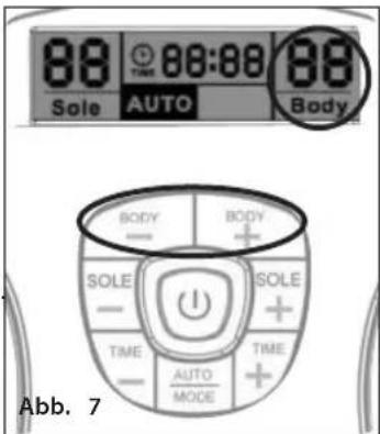
natural_image
Pair of black-and-white striped electronic devices with wires attached (no text or symbols visible)natural_image
Diagram showing a battery connected to a cable with a connector, labeled Abb. 8 (no text or symbols on the diagram itself)natural_image
Close-up of a hand holding a screwdriver touching a small electronic device (no visible text or symbols)natural_image
Close-up of a hand inserting a small electronic component into a white capsule (no visible text or symbols)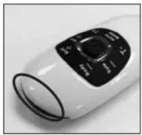
natural_image
Close-up of a white cylindrical device with black control knob (no visible text or symbols)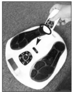
natural_image
Close-up of a hand holding a small object over a white foot with black footprints, no visible text or symbols.Abb. 11
natural_image
Close-up of a person's feet on a white foam roller with black footprints (no text or symbols visible)Vista desde arriba
Vista lateral
natural_image
Diagram of a human footset with circular patterns on the lower side, enclosed in a circular frame (no text or labels)Figura A
natural_image
Silhouette of two black, rounded objects with loop handles, resembling stylized smiley or abstract shapes (no text or symbols)Figura B


$$ A = B = C = 4 0 0 \mu S \quad a = b = 3 2 0 \mu S $$
$$ \text { Voltage } (\text { MAX }) = 5 5 \mathrm{V} $$
$$ A = B = C = 4 0 0 \mu S \quad a = b = 3 2 0 \mu S $$
$$ \text { Voltage } (\text { MAX }) = 5 5 \mathrm{V} $$
$$ A = B = C = 4 0 0 u S \quad a = b = 3 2 0 u S $$
$$ \text { Voltage } (\text { MAX }) = 5 5 \mathrm{V} $$
$$ A = B = C = 4 0 0 \mu S \quad a = b = 3 2 0 \mu S $$
$$ \text { Voltage } (\text { MAX }) = 5 5 \mathrm{V} $$
$$ A = B = C = 4 0 0 \mu S \quad a = b = 3 2 0 \mu S $$
$$ \text { Voltage } (\text { MAX }) = 5 5 \mathrm{V} $$
$$ A = B = C = 4 0 0 \mu S \quad a = b = 3 2 0 \mu S $$
$$ \text { Voltage } (\text { MAX }) = 5 5 \mathrm{V} $$
$$ A = B = C = 4 0 0 u S \quad a = b = 3 2 0 u S $$
$$ \text { Voltage } (\text { MAX }) = 5 5 \mathrm{V} $$
$$ A = B = C = 4 0 0 u S \quad a = b = 3 2 0 u S $$
$$ \text { Voltage } (\text { MAX }) = 5 5 \mathrm{V} $$
$$ A = B = C = 4 0 0 \mu S \quad a = b = 3 2 0 \mu S $$
$$ \text { Voltage } (\text { MAX }) = 5 5 \mathrm{V} $$
$$ A = B = C = 4 0 0 \mu S \quad a = b = 3 2 0 \mu S $$
$$ \text { voltage } (\text { MAX }) = 5 5 \mathrm{V} $$
FUNCIONAMIENTO
natural_image
Illustration of a medical or laboratory procedure with a magnified circular inset showing needle insertion (no text or symbols)Figura 6

natural_image
Nine-panel line drawing showing human body variations in different poses (front, side, torso, chest, hip, arm, chest) without any text or symbols.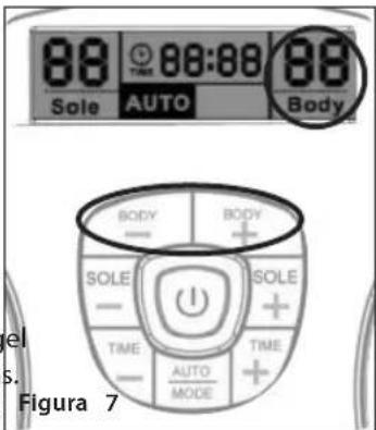
natural_image
Two black-and-white striped electronic earpieces with string tied on a wooden surface (no text or symbols visible)natural_image
Diagram of a device with cable and connector, labeled as Figure 8 (no text or symbols on the diagram itself)natural_image
Close-up of a hand using a screwdriver to apply a small dot on a white computer mouse (no text or symbols visible)
natural_image
Close-up of a hand inserting a battery into a white cylindrical device (no visible text or symbols)
natural_image
Close-up of a white electric fan with black control panel (no visible text or symbols)Figura 8 Figura 9 Figura 10
natural_image
Close-up of a foot massage device with black buttons and a hand adjusting the pad (no visible text or symbols)Figura 11
natural_image
Close-up of a person's feet on a white foam roller with black footprints (no text or symbols visible)Togliersi le scarpe e le calze o i collant. APPOGGIARE I PIEDI NUDI SULLE APPOSITE BASI DI APPOGGIO. IL PIEDE DESTRO SULLA BASE DI APPOGGIO DESTRA E IL PIEDE SINISTRO SULLA BASE DI APPOGGIO SINISTRA. ENTRAMBI I PIEDI DEVONO ESSERE APPOGGIATI SUL DISPOSITIVO PERCHÉ FUNZIONI.

natural_image
Top-down view of a human footset with visible sensor placement and control panel (no text or symbols)Fig. A
natural_image
Silhouette of two black, rounded objects with loop handles, resembling stylized smiley or abstract shapes (no text or symbols)Fig. B


$$ A = B = C = 4 0 0 \mu S \quad a = b = 3 2 0 \mu S $$
$$ \text { Voltage } (\text { MAX }) = 5 5 \mathrm{V} $$
$$ A = B = C = 4 0 0 \mu S \quad s = b = 3 2 0 \mu S $$
$$ \text { Voltage } (\text { MAX }) = 5 5 \mathrm{V} $$
$$ A = B = C = 4 0 0 u S \quad a = b = 3 2 0 u S $$
$$ \text { Voltage } (\text { MAX }) = 5 5 \mathrm{V} $$
$$ A = B = C = 4 0 0 \mu S \quad a = b = 3 2 0 \mu S $$
$$ \text { Voltage } (\text { MAX }) = 5 5 \mathrm{V} $$
$$ A = B = C = 4 0 0 \mu S \quad a = b = 3 2 0 \mu S $$
$$ \text { Voltage } (\text { MAX }) = 5 5 \mathrm{V} $$
$$ A = B = C = 4 0 0 \mu S \quad a = b = 3 2 0 \mu S $$
$$ \text { Voltage } (\text { MAX }) = 5 5 \mathrm{V} $$
$$ A = B = C = 4 0 0 u S \quad a = b = 3 2 0 u S $$
$$ \text { Voltage } (\text { MAX }) = 5 5 \mathrm{V} $$
$$ A = B = C = 4 0 0 u S \quad a = b = 3 2 0 u S $$
$$ \text { Voltage } (\text { MAX }) = 5 5 \mathrm{V} $$
$$ A = B = C = 4 0 0 \mathrm{uS} \quad a = b = 3 2 0 \mathrm{uS} $$
$$ \text { Voltage } (\text { MAX }) = 5 5 \mathrm{V} $$
$$ A = B = C = 4 0 0 \mu S \quad a = b = 3 2 0 \mu S $$
$$ \text { voltage } (\text { MAX }) = 5 5 \mathrm{V} $$
ISTRUZIONI D'USO
Fig. 1

Fig. 2
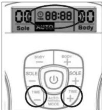
Fig. 3

Fig. 4
Per il corpo
UTILIZZO DEGLI ELETTRODI ADESIVI
natural_image
Illustration of a medical or surgical tool with a magnified inset showing internal components (no text or symbols)Fig. 6

natural_image
Nine abstract line drawings of human figures in various poses, no text or symbols present
ACCESSORI AGGIUNTIVI
natural_image
Close-up of two black-and-white electronic circuit boards with patterned covers, placed on a wooden surface (no text or symbols visible)natural_image
Diagram of a device with cable and plug, labeled Fig. 8 (no text or symbols on the diagram itself)natural_image
Close-up of a hand using a screwdriver to apply a small dot on a white computer mouse (no text or symbols visible)
natural_image
Close-up of a hand inserting a battery into a white cylindrical device (no visible text or symbols)
natural_image
Close-up of a white electric fan with black control panel (no visible text or symbols)natural_image
Close-up of a foot massage device with black buttons and a hand adjusting the pad (no visible text or symbols)Fig. 11
natural_image
Close-up of a person's feet on a white foam roller with black footprints (no text or symbols visible)Descalce-se, incluindo as meias. COLOQUE OS PÉS DESCALÇOS SOBRE AS PLATAFORMAS. O SEU PÉ DIREITO NA PLATAFORMA DIREITA E O PÉ ESQUERDO NA ESQUERDA. PARA QUE O DISPOSITIVO FUNCIONE, DEVE COLOCAR OS DOIS PÉS EM CMA DO DISPOSITIVO.

natural_image
Front view of a human footset with black circular patterns on both sides, enclosed in a circular frame (no text or symbols)Fig. A
natural_image
Silhouette of two black oval objects with loop handles, resembling stylized smiley or abstract shapes (no text or symbols)Fig. B


Diagrama de forma de onda EMS do massajador de corpo e largura de impulso abaixo:
flowchart
graph TD
    subgraph Program 1
        A1["A=B=C=400uS a=b=320uS\nVoltage(MAX)=55V"] --> B1["Waveform with transitions"]
        B1 --> C1["Waveform with transitions"]
    end
    subgraph Program 2
        A2["A=B=C=400uS a=b=320uS\nVoltage(MAX)=55V"] --> B2["Waveform with transitions"]
        B2 --> C2["Waveform with transitions"]
    end
    subgraph Program 3
        A3["A=B=C=400uS a=b=320uS\nVoltage(MAX)=55V"] --> B3["Waveform with transitions"]
        B3 --> C3["Waveform with transitions"]
    end
    subgraph Program 4
        A4["A=B=C=400uS a=b=320uS\nVoltage(MAX)=55V"] --> B4["Waveform with transitions"]
        B4 --> C4["Waveform with transitions"]
    end
    subgraph Program 5
        A5["A=B=C=400uS a=b=320uS\nVoltage(MAX)=55V"] --> B5["Waveform with transitions"]
        B5 --> C5["Waveform with transitions"]
    end
    subgraph Program 6
        A6["A=B=C=400uS a=b=320uS\nVoltage(MAX)=55V"] --> B6["Waveform with transitions"]
        B6 --> C6["Waveform with transitions"]
    end
    subgraph Program 7
        A7["A=B=C=400uS a=b=320uS\nVoltage(MAX)=55V"] --> B7["Waveform with transitions"]
        B7 --> C7["Waveform with transitions"]
    end
    subgraph Program 8
        A8["A=B=C=400uS a=b=320uS\nVoltage(MAX)=55V"] --> B8["Waveform with transitions"]
        B8 --> C8["Waveform with transitions"]
    end
    subgraph Program 9
        A9["A=B=C=400uS a=b=320uS\nVoltage(MAX)=55V"] --> B9["Waveform with transitions"]
        B9 --> C9["Waveform with transitions"]
    end
natural_image
Diagram of a medical or laboratory procedure showing a probe inserted into a circular device with a magnified inset (no text or labels)Fig. 6

natural_image
Nine abstract line drawings of human figures in various poses, no text or symbols present
natural_image
Close-up of two black-and-white electronic circuit boards with patterned covers, placed on a wooden surface (no text or symbols visible)natural_image
Diagram of a device with cable and plug, labeled Fig. 8 (no text or symbols on the diagram itself)natural_image
Close-up of a hand using a screwdriver to apply a small dot on a white computer mouse (no text or symbols visible)
natural_image
Close-up of a hand inserting a battery into a white cylindrical device (no visible text or symbols)
natural_image
Close-up of a white handheld device with black control panel (no visible text or symbols)natural_image
Close-up of a foot massage device with black buttons and a hand adjusting the pad (no visible text or symbols)Fig. 11
natural_image
Close-up of a person's feet on a white foam roller with black footprints (no text or symbols visible)Doe uw schoeisel en sokken of kousen uit. PLAATS UW BLOTE VOETEN OP DE VOETENPADS. UW RECHTERVOET OP DE RECHTERVOETZOOL, EN UW LINKERVOET OP DE LINKERVOETZOOL. BEIDE VOETEN MOETEN OP HET APPARAAT STAAN OM HET APPARAAT TE LATEN WERKEN.

Bovenaanzicht
Zijaanzicht
natural_image
Diagram of a human footset with circular patterns and control panel (no text or labels)afb. A
natural_image
Silhouette of two black oval objects with loop handles, resembling stylized smiley or abstract shapes (no text or symbols)afb. B


afb.1

afb.2

afb.3
afb.4
Voor het lichaam
natural_image
Illustration of a medical or surgical procedure with instruments and tubing, no text or symbols present
natural_image
Nine abstract line drawings of human figures in various poses, no text or symbols present
natural_image
Close-up of two black-and-white electronic circuit boards with patterned covers, placed on a wooden surface (no text or symbols visible)natural_image
Simple line drawing of a cable being inserted into a device labeled 'afb. 8' (no text or symbols on the diagram itself)natural_image
Close-up of a hand using a screwdriver to apply material to a small white object (no text or symbols visible)
natural_image
Close-up of a hand inserting a small electronic device into a white cylindrical device (no visible text or symbols)
natural_image
Close-up of a white handheld device with black control panel (no visible text or symbols)natural_image
Close-up of a white foam roller with black foot buttons and a hand holding a small object, showing a circular arrow indicating rotation (no text or symbols visible)afb. 11
Opmerking over batterijen:
natural_image
Close-up of a person's feet on a white foam roller with black footprints (no text or symbols visible)natural_image
Diagram of a human footset with circular patterns on the peric� (no text or labels)Şek. A
natural_image
Silhouette of two black oval objects with loop handles, resembling stylized smiley or abstract shapes (no text or symbols)Şek. B


$$ A = B = C = 4 0 0 \mu S \quad a = b = 3 2 0 \mu S $$
$$ \text { Voltage } (\text { MAX }) = 5 5 \mathrm{V} $$
$$ A = B = C = 4 0 0 \mu S \quad a = b = 3 2 0 \mu S $$
$$ \text { Voltage } (\text { MAX }) = 5 5 \mathrm{V} $$
$$ A = B = C = 4 0 0 u S \quad a = b = 3 2 0 u S $$
$$ \text { Voltage } (\text { MAX }) = 5 5 \mathrm{V} $$
$$ A = B = C = 4 0 0 \mu S \quad a = b = 3 2 0 \mu S $$
$$ \text { Voltage } (\text { MAX }) = 5 5 \mathrm{V} $$
$$ A = B = C = 4 0 0 \mu S \quad a = b = 3 2 0 \mu S $$
$$ \text { Voltage } (\text { MAX }) = 5 5 \mathrm{V} $$
$$ A = B = C = 4 0 0 \mu S \quad a = b = 3 2 0 \mu S $$
$$ \text { Voltage } (\text { MAX }) = 5 \text { SV } $$
$$ A = B = C = 4 0 0 u S \quad a = b = 3 2 0 u S $$
$$ \text { Voltage } (\text { MAX }) = 5 5 \mathrm{V} $$
$$ A = B = C = 4 0 0 u S \quad a = b = 3 2 0 u S $$
$$ \text { Voltage } (\text { MAX }) = 5 5 \mathrm{V} $$
$$ A = B = C = 4 0 0 \mu S \quad a = b = 3 2 0 \mu S $$
$$ \text { Voltage } (\text { MAX }) = 5 5 \mathrm{V} $$
$$ A = B = C = 4 0 0 \mu S \quad a = b = 3 2 0 \mu S $$
$$ \text { voltage } (\text { MAX }) = 5 5 \mathrm{V} $$
NASIL ÇALIŞTIRILIR
natural_image
Diagram of a medical or laboratory procedure showing a probe inserted into a circular component, with two separate views of the same device (no text or symbols present)
natural_image
Grid of nine abstract line drawings showing human and animal anatomical structures (no text or symbols)
natural_image
Pair of black-and-white striped electronic circuit boards with wires attached (no text or symbols visible)natural_image
Line drawing of a device with cable and connector, no text or symbols presentnatural_image
Close-up of a hand using a screwdriver to apply a small dot on a white computer mouse (no text or symbols visible)
natural_image
Close-up of a hand inserting a battery into a white cylindrical device (no visible text or symbols)
natural_image
Close-up of a white electric fan with black control panel (no visible text or symbols)natural_image
Close-up of a foot massage device with black buttons and a hand adjusting the pad (no visible text or symbols)Şek. 11
natural_image
Close-up of a person's feet on a white foam roller with black footprints (no text or symbols visible)natural_image
Top-down view of a human footset with circular patterns and a control panel (no text or symbols)Σχ. A
natural_image
Silhouette of two black, rounded objects with loop handles (no text or symbols)Σχ. B


Σχ. 1
Σχ.2
Σχ. 3

Σχ. 4
Για το σώμα
natural_image
Illustration of a medical or laboratory procedure with a magnified circular component and two separate test tubes (no text or symbols present)Σχ.6

natural_image
Nine abstract line drawings of human figures in various poses, no text or symbols present
natural_image
Close-up of two black-and-white striped electronic circuit boards with wires attached (no text or symbols visible)natural_image
Line drawing of a device with a cable and plug, labeled 'Σχ. 8' (no text or symbols on the diagram itself)natural_image
Close-up of a hand using a screwdriver to apply a small dot on a white computer mouse (no text or symbols visible)
natural_image
Close-up of a hand inserting a small electronic device into a white cylindrical device (no visible text or symbols)
natural_image
Close-up of a white electric fan with black control panel (no visible text or symbols)Σχ. 8 Σχ. 9 Σχ. 10
natural_image
Close-up of a foot massage device with black buttons and a hand adjusting the pad (no visible text or symbols)Σχ. 11
natural_image
Close-up of a person's feet on a white foam roller with black footprints and circular buttons (no text or symbols visible)natural_image
Diagram of a human footset with circular patterns on the sides, enclosed in a circular device (no text or labels)рис. А
natural_image
Two black, elongated objects with loop handles, resembling stylized oocytes or gelatinos (no text or symbols)рис. В


natural_image
Illustration of a medical or laboratory setup with wires, a magnified circular component, and two separate views (no text or symbols)рис. 6

natural_image
Nine abstract line drawings of human figures in various poses, no text or symbols present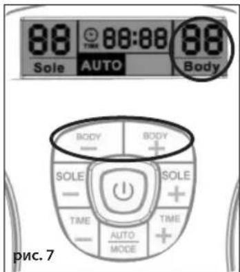
natural_image
Pair of black-and-white striped electronic circuit components with wires attached (no text or symbols visible)natural_image
Line drawing of a cable being inserted into a device (no text or symbols)Fig. 8
natural_image
Close-up of a hand using a screwdriver to apply liquid onto a white plastic object (no text or symbols visible)natural_image
Close-up of a hand inserting a small electronic device into a white plastic housing (no visible text or symbols)natural_image
Close-up of a white handheld electronic device with black control panel (no visible text or symbols)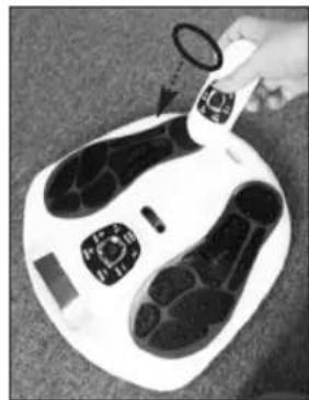
natural_image
Close-up of a white foot with black feet and a small circular object, possibly a device or sensor device (no visible text or symbols)рис. 11
natural_image
Close-up of a person's feet on a white foam roller with black footprints (no text or symbols visible)Zdjąć obuwie i skarpetki lub pończochy. UMIEŚCIĆ BOSE STOPY NA PODKŁADKACH DO STÓP. PRAWĄ NOGĘ NALEŻY UMIEŚCIĆ NA PRAWEJ PODKŁADCE, A LEWĄ STOPĘ NA LEWEJ PODKŁADCE. ABY URZĄDZENIE DZIAŁAŁO PRAWIDŁOWO, OBYDWIE STOPY MUSZĄ ZNAJDOWAĆ SIĘ NA PODKŁADKACH.

WAŻNE INFORMACJE DLA KLIENTA
ZALECA SIĘ PRZECZYTANIE PONIŻSZYCH INFORMACJI:
natural_image
Top-down schematic of a human footset with circular patterns and control panel (no text or labels)Rys. A
natural_image
Silhouette of two black oval objects with loop handles, resembling stylized menses or accessories (no text or symbols)Rys. B


$$ A = B = C = 4 0 0 \mu S \quad a = b = 3 2 0 \mu S $$
$$ \text { Voltage } (\text { MAX }) = 5 5 \mathrm{V} $$
$$ A = B = C = 4 0 0 \mu S \quad a = b = 3 2 0 \mu S $$
$$ \text { Voltage } (\text { MAX }) = 5 5 \mathrm{V} $$
$$ A = B = C = 4 0 0 u S \quad a = b = 3 2 0 u S $$
$$ \text { Voltage } (\text { MAX }) = 5 5 \mathrm{V} $$
$$ A = B = C = 4 0 0 \mu S \quad a = b = 3 2 0 \mu S $$
$$ \text { Voltage } (\text { MAX }) = 5 5 \mathrm{V} $$
$$ A = B = C = 4 0 0 \mu S \quad a = b = 3 2 0 \mu S $$
$$ \text { Voltage } (\text { MAX }) = 5 5 \mathrm{V} $$
$$ A = B = C = 4 0 0 \mu S \quad a = b = 3 2 0 \mu S $$
$$ \text { Voltage } (\text { MAX }) = 5 \text { SV } $$
$$ A = B = C = 4 0 0 u S \quad a = b = 3 2 0 u S $$
$$ \text { Voltage } (\text { MAX }) = 5 5 \mathrm{V} $$
$$ A = B = C = 4 0 0 u S \quad a = b = 3 2 0 u S $$
$$ \text { Voltage } (\text { MAX }) = 5 5 \mathrm{V} $$
$$ A = B = C = 4 0 0 \mu S \quad a = b = 3 2 0 \mu S $$
$$ \text { Voltage } (\text { MAX }) = 5 5 \mathrm{V} $$
$$ A = B = C = 4 0 0 \mu S \quad a = b = 3 2 0 \mu S $$
$$ \text { Voltage } (\text { MAX }) = 5 5 \mathrm{V} $$
OBSŁUGA

natural_image
Illustration of a medical or laboratory setup with wires, a magnified circle, and two sets of ear-shaped objects (no text or symbols)Rys. 6
natural_image
Nine abstract line drawings of human figures in various poses, no text or symbols present
natural_image
Two black-and-white electronic test strips with patterned covers, placed on a plain surface (no text or symbols visible)natural_image
Line drawing of a device with a cable and plug, labeled 'Rys. 8' (no text or symbols on the diagram itself)natural_image
Close-up of a hand using a screwdriver to apply a small dot on a white computer mouse (no text or symbols visible)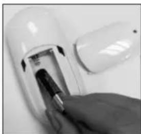
natural_image
Close-up of a hand inserting a small electronic device into a white cylindrical device (no visible text or symbols)
natural_image
Close-up of a white electric fan with black control panel (no visible text or symbols)natural_image
Top-down view of a white foam roller with black foot buttons and a hand holding a small object (no text or symbols visible)Rys. 11
natural_image
Close-up of a person's feet on a white foam roller with black footprints (no text or symbols visible)Ta av dina skor och strumpor eller strumpbyxor. PLACERA DINA BARA FÖTTER PÅ FOTDYNORNA. DIN HÖGRA FOT PÅ DEN HÖGRA FOTDYNAN OCH DIN VÄNSTRA FOT PÅ DEN VÄNSTRA FOTDYNAN. BÅDA FÖTTERNA MÅSTE VARA PÅ ENHETEN FÖR ATT DEN SKA FUNGERA.

Toppöversikt

Sidoöversikt
natural_image
Diagram of a human footset with circular patterns and a control panel (no text or labels)Fig. A
natural_image
Silhouette of two black, rounded objects with loop handles, resembling stylized smiley or abstract shapes (no text or symbols)Fig. B


flowchart
graph TD
    subgraph Program 1
        A1["A=8=C=400uS a=b=320uS\nVoltage(MAX)=55V"] --> B1["Waveform with alternating blocks"]
        B1 --> C1["Output"]
    end
    subgraph Program 2
        A2["A=B=C=400uS a=b=320uS\nVoltage(MAX)=55V"] --> B2["Waveform with alternating blocks"]
        B2 --> C2["Output"]
    end
    subgraph Program 3
        A3["A=B=C=400uS a=b=320uS\nVoltage(MAX)=55V"] --> B3["Waveform with alternating blocks"]
        B3 --> C3["Output"]
    end
    subgraph Program 4
        A4["A=B=C=400uS a=b=320uS\nVoltage(MAX)=55V"] --> B4["Waveform with alternating blocks"]
        B4 --> C4["Output"]
    end
    subgraph Program 5
        A5["A=B=C=400uS a=b=320uS\nVoltage(MAX)=55V"] --> B5["Waveform with alternating blocks"]
        B5 --> C5["Output"]
    end
    subgraph Program 6
        A6["A=B=C=400uS a=b=320uS\nVoltage(MAX)=55V"] --> B6["Waveform with alternating blocks"]
        B6 --> C6["Output"]
    end
    subgraph Program 7
        A7["A=B=C=400uS a=b=320uS\nVoltage(MAX)=55V"] --> B7["Waveform with alternating blocks"]
        B7 --> C7["Output"]
    end
    subgraph Program 8
        A8["A=B=C=400uS a=b=320uS\nVoltage(MAX)=55V"] --> B8["Waveform with alternating blocks"]
        B8 --> C8["Output"]
    end
    subgraph Program 9
        A9["A=B=C=400uS a=b=320uS\nVoltage(MAX)=55V"] --> B9["Waveform with alternating blocks"]
        B9 --> C9["Output"]
    end
HUR MAN ANVÄNDER
För fötterna – SOLE
Fig. 1

Fig. 2

Fig. 3

Fig. 4

För kroppen
ANVÄNDA GELDYNORNA
natural_image
Diagram of a medical or laboratory setup with wires, a magnified circular component, and two separate views (no text or symbols)Fig. 6

natural_image
Nine abstract line drawings of human figures in various poses, no text or symbols present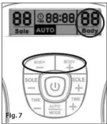
natural_image
Close-up of two black-and-white electronic earpieces with patterned soles, attached to a white string (no text or symbols visible)natural_image
Diagram showing a device connected to a cable with a connector, labeled Fig. 8 (no text or symbols on the diagram itself)natural_image
Close-up of a hand using a screwdriver to apply a small dot on a white computer mouse (no text or symbols visible)
natural_image
Close-up of a hand inserting a battery into a white cylindrical device (no visible text or symbols)
natural_image
Close-up of a white handheld device with black control panel (no visible text or symbols)natural_image
Close-up of a foot massage device with black buttons and a hand adjusting the pad (no visible text or symbols)Fig. 11
natural_image
Close-up of a person's feet on a white foam roller with black footprints (no text or symbols visible)Aftag fodtøj og sokker/strømper. ANBRING DINE BARE F∅DDER PÅ FODPUDERNE. H∅JRE FOD PÅ H∅JRE FODPUDE OG VENSTRE FOD PÅ VENSTRE FODPUDE. BEGGE F∅DDER SKAL VÆRE PÅ APPARATET, FOR AT DET VIRKER.


Set oppefra

Set fra siden
natural_image
Diagram of a human footset with circular patterns on both sides, enclosed in a circular device (no text or labels)Fig. A
natural_image
Silhouette of two black, oval-shaped objects with loop handles, resembling stylized smiley or abstract forms (no text or symbols)Fig. B
På gelpuden er det sorte område på den klæbende del elektrodeområdet for kroppen, det måler 5 x 9 cm (se fig. B).
UDGANGSSIGNALETS B∅LGEFORMER FOR CIRCULATOR
B∅LGEFORM FOR UDGANGSSIGNAL
***UDGANGSSIGNALERNE HAR INGEN CD-KOMPONENT
FODSÅLSMASSAGEANORDNING (ved 1 kΩ belastning) Autotilstand veksler mellem de 14 programmer under apparatets drift og gentager dem automatisk.


flowchart
graph TD
    subgraph Program 1
        A1["A=8=C=400uS"] -->|a=b=320uS| B1["Voltage (MAX) =55V"]
    end
    subgraph Program 2
        A2["A=8=C=400uS"] -->|a=b=320uS| B2["Voltage (MAX) =55V"]
    end
    subgraph Program 3
        A3["A=8=C=400uS"] -->|a=b=320uS| B3["Voltage (MAX) =55V"]
    end
    subgraph Program 4
        A4["A=8=C=400uS"] -->|a=b=320uS| B4["Voltage (MAX) =55V"]
    end
    subgraph Program 5
        A5["A=8=C=400uS"] -->|a=b=320uS| B5["Voltage (MAX) =55V"]
    end
    subgraph Program 6
        A6["A=8=C=400uS"] -->|a=b=320uS| B6["Voltage (MAX) =55V"]
    end
    subgraph Program 7
        A7["A=8=C=400uS"] -->|a=b=320uS| B7["Voltage (MAX) =55V"]
    end
    subgraph Program 8
        A8["A=8=C=400uS"] -->|a=b=320uS| B8["Voltage (MAX) =55V"]
    end
    subgraph Program 9
        A9["A=8=C=400uS"] -->|a=b=320uS| B9["Voltage (MAX) =55V"]
    end
    subgraph Program 10
        A10["A=8=C=400uS"] -->|a=b=320uS| B10["Voltage (MAX) =55V"]
BETJENING
Til fod - SOLE
natural_image
Illustration of a medical or laboratory procedure with wires, probes, and two labeled anatomical structures (no text or symbols present)Fig. 6

natural_image
Grid of nine abstract line drawings showing human and animal anatomical structures (no text or symbols)
natural_image
Close-up of two black-and-white electronic circuit boards with patterned covers, placed on a wooden surface (no text or symbols visible)! Pas på dine gelpuder
natural_image
Diagram of a cable being inserted into a device, labeled Fig. 8 (no text or symbols on the diagram itself)natural_image
Close-up of a hand using a screwdriver to apply a small dot on a white computer mouse (no text or symbols visible)natural_image
Close-up of a hand inserting a small electronic device into a white cylindrical device (no visible text or symbols)
natural_image
Close-up of a white handheld device with black control panel (no visible text or symbols)natural_image
Close-up of a foot massage device with black buttons and a hand adjusting the pad (no visible text or symbols)Fig. 11
natural_image
Close-up of a person's feet on a white foam roller with black footprints and circular buttons (no text or symbols visible)Fjern sko og sokker eller strømper. PLASSER DE NAKNE F∅TTENE PÅ FOTPLATENE. DIN H∅YRE FOT PÅ H∅YRE FOTPLATE OG DIN VENSTRE FOT PÅ VENSTRE FOTPLATE. BEGGE F∅TTENE MÅ VÆRE PLASSERT PÅ ENHETEN FOR AT DEN SKAL FUNGERE.
natural_image
Diagram of a human footset with circular patterns and control panel (no text or labels)Fig. A
natural_image
Silhouette of two black, rounded objects with loop handles, resembling stylized smiley or abstract shapes (no text or symbols)fig. B


natural_image
Illustration of a medical or laboratory procedure with a magnified circular component and two separate test tubes (no text or symbols present)fig. 6

natural_image
Grid of nine abstract line drawings showing human and animal anatomical structures (no text or symbols)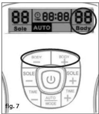
natural_image
Close-up of two black-and-white electrocution test clips with patterned soles, attached to a white string (no text or symbols visible)natural_image
Line drawing of a device with a cable and plug, labeled 'fig. 8' (no text or symbols on the diagram itself)natural_image
Close-up of a hand using a screwdriver to apply a small dot on a white computer mouse (no text or symbols visible)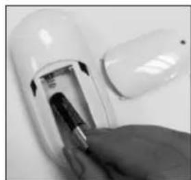
natural_image
Close-up of a hand inserting a battery into a white cylindrical device (no visible text or symbols)
natural_image
Close-up of a white electric fan with black control panel (no visible text or symbols)fig. 8 fig. 9 fig. 10
natural_image
Close-up of a foot massage device with black buttons and a hand adjusting the pad (no visible text or symbols)fig. 11
FEILS∅KING OG VEDLIKEHOLD
natural_image
Close-up of a person's feet on a white foam roller with black footprints (no text or symbols visible)Poista jalkineesi ja sukat tai sukkahousut. ASTU PALJAIN JALOIN JALKATYYNYILLE. ASETA OIKEA JALKA OIKEALLE TYYNYLLE JA VASEN VASEMMALLE. MOLEMPIEN JALKOJEN TULEE OLLA LAITTEEN PÄÄLLÄ, JOTTA TÄMÄ TOIMISI.

natural_image
Diagram of a human footset with circular patterns and control panel (no text or labels)Kuva A
natural_image
Silhouette of two black, rounded objects with loop handles, resembling stylized smiley or abstract shapes (no text or symbols)Kuva B


$$ A = B = C = 4 0 0 \mu S \quad a = b = 3 2 0 \mu S $$
$$ \text { Voltage } (\text { MAX }) = 5 5 \mathrm{V} $$
$$ A = B = C = 4 0 0 \mu S \quad s = b = 3 2 0 \mu S $$
$$ \text { Voltage } (\text { MAX }) = 5 5 \mathrm{V} $$
$$ A = B = C = 4 0 0 u S \quad a = b = 3 2 0 u S $$
$$ \text { Voltage } (\text { MAX }) = 5 5 \mathrm{V} $$
$$ A = B = C = 4 0 0 \mu S \quad a = b = 3 2 0 \mu S $$
$$ \text { Voltage } (\text { MAX }) = 5 5 \mathrm{V} $$
$$ A = B = C = 4 0 0 \mu S \quad a = b = 3 2 0 \mu S $$
$$ \text { Voltage } (\text { MAX }) = 5 5 \mathrm{V} $$
$$ A = B = C = 4 0 0 \mu S \quad a = b = 3 2 0 \mu S $$
$$ \text { Voltage } (\text { MAX }) = 5 5 \mathrm{V} $$
$$ A = B = C = 4 0 0 u S \quad a = b = 3 2 0 u S $$
$$ \text { Voltage } (\text { MAX }) = 5 5 \mathrm{V} $$
$$ A = B = C = 4 0 0 u S \quad a = b = 3 2 0 u S $$
$$ \text { Voltage } (\text { MAX }) = 5 5 \mathrm{V} $$
$$ A = B = C = 4 0 0 \mu S \quad a = b = 3 2 0 \mu S $$
$$ \text { Voltage } (\text { MAX }) = 5 5 \mathrm{V} $$
$$ A = B = C = 4 0 0 \mu S \quad a = b = 3 2 0 \mu S $$
$$ \text { Voltage } (\text { MAX }) = 5 5 \mathrm{V} $$
KÄYTTÖOHJEET
natural_image
Grid of nine abstract line drawings showing human and animal anatomical structures (no text or symbols)
natural_image
Close-up of two black-and-white electronic earpieces with patterned soles, attached to a white string (no text or symbols visible)Geelityynyjen hoito
natural_image
Line drawing of a Kuva 8 device with cable and connector (no text or symbols on the diagram itself)natural_image
Close-up of a hand using a screwdriver to apply a small dot on a white computer mouse (no text or symbols visible)natural_image
Close-up of a hand inserting a small electronic component into a white cylindrical device (no visible text or symbols)
natural_image
Close-up of a white handheld device with black control panel (no visible text or symbols)natural_image
Close-up of a foot massage device with black buttons and a hand adjusting the pad (no visible text or symbols)Kuva 11
natural_image
Close-up of a computer mouse with a magnifying glass highlighting the lens (no text or symbols visible)natural_image
Close-up of a person's feet on a white foam roller with black foot markers (no text or symbols visible)Zujte si boty a ponožky nebo punčochy. POLOŽTE BOSÁ CHODIDLA NA NOŽNÍ PODLOŽKY. PRAVOU NOHU POLOŽTE NA PRAVOU PODLOŽKU A LEVOU NOHU NA LEVOU PODLOŽKU. ABY PRÍSTROJ FUNGOVAL, MUSÍ BÝT OBĚ CHODIDLA POLOŽENA NA PODLOŽKÁCH.
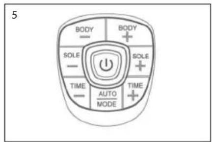
Pohled shora
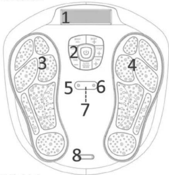
Pohled zboku
natural_image
Diagram of a human footset with circular patterns and control panel (no text or labels)obr. A
natural_image
Silhouette of two black oval objects with loop handles, resembling stylized smiley or abstract shapes (no text or symbols)Obr. B


$$ A = B = C = 4 0 0 \mu S \quad a = b = 3 2 0 \mu S $$
$$ \text { Voltage } (\text { MAX }) = 5 5 \mathrm{V} $$
$$ A = B = C = 4 0 0 \mu S \quad s = b = 3 2 0 \mu S $$
$$ \text { Voltage } (\text { MAX }) = 5 5 \mathrm{V} $$
$$ A = B = C = 4 0 0 u S \quad a = b = 3 2 0 u S $$
$$ \text { Voltage } (\text { MAX }) = 5 5 \mathrm{V} $$
$$ A = B = C = 4 0 0 \mu S \quad a = b = 3 2 0 \mu S $$
$$ \text { Voltage } (\text { MAX }) = 5 5 \mathrm{V} $$
$$ A = B = C = 4 0 0 \mu S \quad a = b = 3 2 0 \mu S $$
$$ \text { Voltage } (\text { MAX }) = 5 5 \mathrm{V} $$
$$ A = B = C = 4 0 0 \mu S \quad a = b = 3 2 0 \mu S $$
$$ \text { Voltage } (\text { MAX }) = 5 5 \mathrm{V} $$
$$ A = B = C = 4 0 0 u S \quad a = b = 3 2 0 u S $$
$$ \text { Voltage } (\text { MAX }) = 5 5 \mathrm{V} $$
$$ A = B = C = 4 0 0 u S \quad a = b = 3 2 0 u S $$
$$ \text { Voltage } (\text { MAX }) = 5 5 \mathrm{V} $$
$$ A = B = C = 4 0 0 \mu S \quad a = b = 3 2 0 \mu S $$
$$ \text { Voltage } (\text { MAX }) = 5 5 \mathrm{V} $$
$$ A = B = C = 4 0 0 u S \quad a = b = 3 2 0 u S $$
$$ \text { Voltage } (\text { MAX }) = 5 5 \mathrm{V} $$
POUŽITÍ PŘÍSTROJE
Pro chodidla - SOLE


natural_image
Grid of nine abstract line drawings showing human and animal anatomical structures (no text or symbols)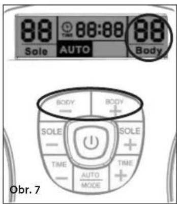
natural_image
Close-up of two black-and-white striped electronic circuit components with wires attached (no text or symbols visible)natural_image
Close-up of a hand holding a screwdriver near a transparent computer mouse (no visible text or symbols)Obr. 8
natural_image
Close-up of a hand using a screwdriver to apply a small object on a white surface (no text or symbols visible)Obr. 8 Obr. 9 Obr. 10

natural_image
Close-up of a hand inserting a plug into a white cylindrical device (no visible text or symbols)
natural_image
Close-up of a white handheld device with black control panel (no visible text or symbols)natural_image
Close-up of a white foam roller with black footprints and a hand holding a small object, no visible text or symbols.Obr. 11
natural_image
Close-up of a person's feet on a white foam roller with black footprints (no text or symbols visible)natural_image
Diagram of a human footset with circular patterns and control panel (no text or labels)A ábra
natural_image
Silhouette of two black, oval-shaped objects with loop handles, resembling stylized smiley or abstract forms (no text or symbols)B. ábra


natural_image
Illustration of a medical or laboratory setup with two sets of test probes and a circular device, no visible text or symbols.
natural_image
Nine abstract line drawings of human figures in various poses, no text or symbols present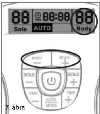
natural_image
Pair of black-and-white electrocution test probes with hatched patterns, attached to a white string (no text or symbols visible)A gélpárnák ápolása
natural_image
Close-up of a hand using a screwdriver to apply a small dot on a white computer mouse (no text or symbols visible)
natural_image
Close-up of a hand inserting a small electronic device into a white cylindrical device (no visible text or symbols)
natural_image
Close-up of a white handheld device with black control panel (no visible text or symbols)- ábra 9. ábra 10. ábra
natural_image
Close-up of a foot massage device with black buttons and a hand adjusting the pad (no visible text or symbols)- ábra
natural_image
Close-up of a person's feet on a white foam roller with black footprints and circular buttons (no text or symbols visible)Vyzujte si topánky a pančuchy alebo ponožky. POLOŽTE BOSÉ CHODIDLÁ NA PODLOŽKY PRE CHODIDLÁ. PRAVÉ CHODIDLO POLOŽTE NA PRAVÚ PODLOŽKU A L'AVÉ CHODIDLO NA L'AVÚ PODLOŽKU. ZARIADENIE BUDE FUNGOVAŤ LEN VTEDY, KEĎ BUDÚ OBE CHODIDLÁ NA PODLOŽKÁCH.
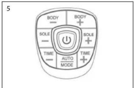
natural_image
Diagram of a human footset with circular patterns and control panel (no text or labels)Obr. A
natural_image
Silhouette of two black oval objects with loop handles, resembling stylized smiley or abstract shapes (no text or symbols)Obr. B
flowchart
graph TD
    subgraph Program 1
        A1["A=B=C=400uS a=b=320uS\nVoltage(MAX)=60V"] --> B1["Waveform with alternating 'a' and 'b' segments"]
    end
    subgraph Program 2
        A2["A=B=C=400uS a=b=320uS\nVoltage(MAX)=60V"] --> B2["Waveform with alternating 'a' and 'b' segments"]
    end
    subgraph Program 3
        A3["A=B=C=400uS*19 a=b=320uS*19\nVoltage(MAX)=60V"] --> B3["Waveform with alternating 'a' and 'b' segments"]
    end
    subgraph Program 4
        A4["A=B=C=400uS a=b=320uS\nVoltage(MAX)=60V"] --> B4["Waveform with alternating 'a' and 'b' segments"]
    end
    subgraph Program 5
        A5["A=B=C=400uS a=b=320uS\nVoltage(MAX)=60V"] --> B5["Waveform with alternating 'a' and 'b' segments"]
    end
    subgraph Program 6
        A6["A=B=C=400uS*3 a=b=320uS*3\nVoltage(MAX)=60V"] --> B6["Waveform with alternating 'a' and 'b' segments"]
    end
    subgraph Program 7
        A7["A=B=C=400uS a=b=320uS\nVoltage(MAX)=60V"] --> B7["Waveform with alternating 'a' and 'b' segments"]
    end
    subgraph Program 8
        A8["A=aB b C"] --> B8["Waveform with alternating 'a' and 'b' segments"]
    end
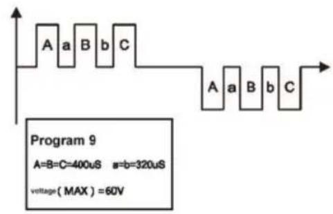
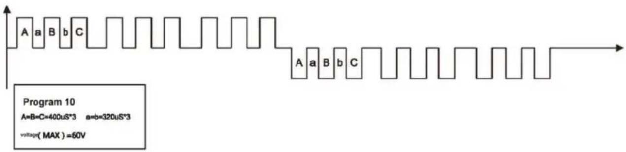
other
| Segment | Value | |---------|--------------| | A | 400uS*3 | | B | 320uS*3 | | C | 60V |


Priebeh impulzu EMS masáže tela a graf šírky impulzu:
Počas zat'aženia 1 kΩ pri pripojení s elektródovou čast'ou pre telo
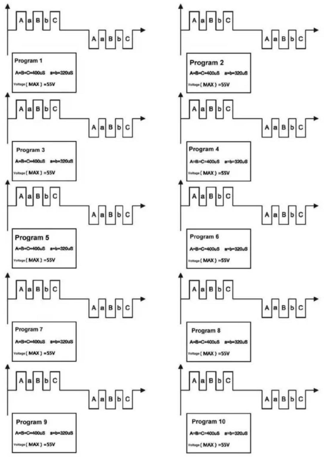
flowchart
graph TD
    A1["Program 1\nA=B=C=400uS a=b=320uS\nVoltage(MAX)=55V"] --> B1["Program 2\nA=B=C=400uS a=b=320uS\nVoltage(MAX)=55V"]
    A2["Program 3\nA=B=C=400uS a=b=320uS\nVoltage(MAX)=55V"] --> B2["Program 4\nA=B=C=400uS a=b=320uS\nVoltage(MAX)=55V"]
    A3["Program 5\nA=B=C=400uS a=b=320uS\nVoltage(MAX)=55V"] --> B3["Program 6\nA=B=C=400uS a=b=320uS\nVoltage(MAX)=55V"]
    A4["Program 7\nA=B=C=400uS a=b=320uS\nVoltage(MAX)=55V"] --> B4["Program 8\nA=B=C=400uS a=b=320uS\nVoltage(MAX)=55V"]
    A5["Program 9\nA=B=C=400uS a=b=320uS\nVoltage(MAX)=55V"] --> B5["Program 10\nA=B=C=400uS a=b=320uS\nVoltage(MAX)=55V"]
SPÔSOB POUŽITIA
Pre dolné končatiny – SOLE (Chodidlo)
DÔLEŽITÉ INFORMÁCIE:


natural_image
Grid of nine abstract line drawings showing human and animal anatomical structures (no text or symbols)
natural_image
Close-up of two black-and-white electronic circuit boards with patterned covers, placed on a wooden surface (no text or symbols visible)natural_image
Simple line drawing of a device with a cable and connector, labeled 'Obr. 8' (no text or symbols on the diagram itself)natural_image
Close-up of a hand using a screwdriver to apply a small dot on a white computer mouse (no text or symbols visible)Obr. 8 Obr. 9 Obr. 10

natural_image
Close-up of a hand inserting a small electronic component into a white cylindrical device (no visible text or symbols)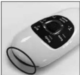
natural_image
Close-up of a white handheld device with black control panel (no visible text or symbols)natural_image
Close-up of a foot massage device with black buttons and a hand adjusting the pad (no visible text or symbols)Obr. 11