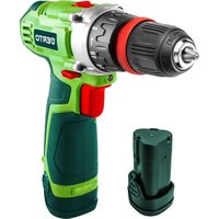
50G273 - Drill Verto - Free user manual and instructions
Find the device manual for free 50G273 Verto in PDF.


User questions about 50G273 Verto
0 question about this device. Answer the ones you know or ask your own.
Ask a new question about this device
Download the instructions for your Drill in PDF format for free! Find your manual 50G273 - Verto and take your electronic device back in hand. On this page are published all the documents necessary for the use of your device. 50G273 by Verto.
USER MANUAL 50G273 Verto
natural_image
Simple line drawing of an open book with no text or symbols visible50G273
text_image
1 2 3 12 1 18 4 8 7 6 5 VERTO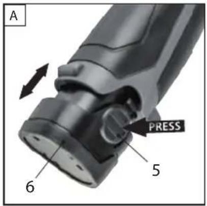
text_image
A PRESS 5 6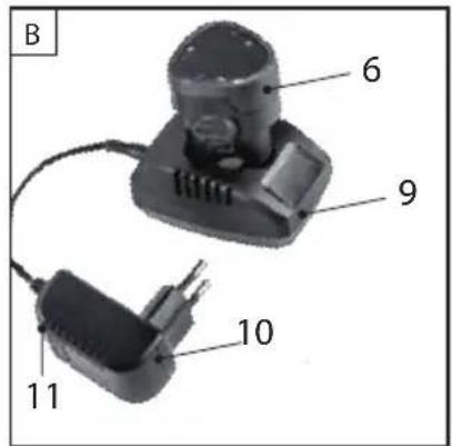
text_image
B 6 9 10 11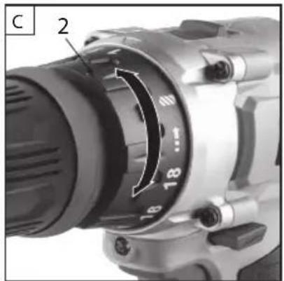
natural_image
Close-up of a mechanical device with a dial indicator and numbered component (no readable text or symbols)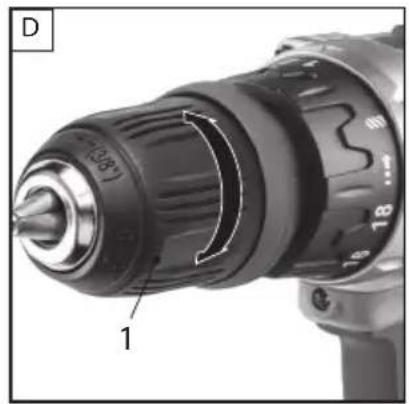
natural_image
Close-up of a drill bit with a curved arrow indicating rotation (no text or symbols visible)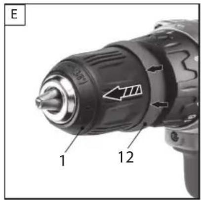
text_image
E 1 12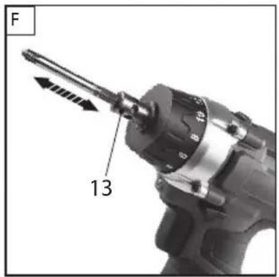
text_image
F 13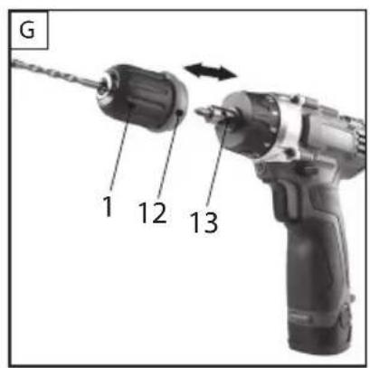
text_image
G 1 12 13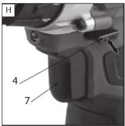
text_image
H 4 7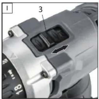
natural_image
Close-up of a mechanical device with labeled parts (1, 3) and directional arrows, no readable text or symbols beyond labelsPL INSTRUKCJA OBSŁUGI....5
GB INSTRUCTION MANUAL 11
SR UPUTSTVO ZA UPOTREBU 66
GR ODHΓIEΣ XPHΣΗΣ 70
ES INSTRUCCIONES DE USO....74
IT MANUALE PER L'USO....78
FR MANUEL D'INSTRUCTION....86
INSTRUKCJA ORYGINALNA (OBSŁUGI)
WIERTARKO - WKRETARKA AKUMULATOROWA 50G273
UWAGA: PRZED PRZYSTĄPIENIEM DO UŻYTKOWANIA ELEKTRONARZĘDZIA NALEŻY UWAŻNIE PRZECZYTAĆ NINIEJSZĄ INSTRUKCJĘ I ZACHOWAĆ JĄ DO DALSZEGO WYKORZYSTANIA.
SZCZEGÓŁOWE PRZEPISY BEZPIECZEŃSTWA
SZCZEGÓLNE PRZEPISY DOTYCZĄCE BEZPIECZNEJ PRACY WIERTARKO - WKRETARKA
text_image
GTX SERVICE
text_image
QR code image containing encoded data, no visible human-readable textC€
/Signed for and on behalf of:/
/GRUPA TOPEX Quality Agent/
CAUTION: BEFORE USING THE POWER TOOL READ THIS MANUAL CAREFULLY AND KEEP IT FOR FUTURE REFERENCE.
DETAILED SAFETY REGULATIONS
SPECIFIC REGULATIONS REGARDING SAFE USE OF THE DRILL
- Use ear protectors and safety goggles when operating the drill. Exposure to noise may cause hearing loss. Metal dust and other particles floating in the air may cause permanent eye injury.
- Use additional handles supplied with the tool. Loss of control may cause operator personal injury.
ADDITIONAL RULES FOR SAFE DRILL OPERATION
- Use only recommended battery and charger.
- Always keep the battery away from sources of fire. Do not leave the battery for a long time in high temperature (in direct sunlight, in proximity of heaters and wherever the temperature exceeds 50^ ).
- The battery charging time cannot be longer than 8 hours, otherwise the battery may be damaged.
- Battery charging process should be supervised by the user.
- Avoid charging the battery in temperature below 0^ .
- Charger supplied with the drill is designed for operation with this product only. Do not use it for other purposes.
- Do not put any metal objects into the charger.
- Do not change direction of spindle rotation when the tool is operating. Otherwise the drill may be damaged.
- Use soft, dry cloth to clean the drill. Never use detergents or alcohol.
- Disconnect the charger from power supply before cleaning.
- If you intend to charge more than one battery successively, make a 30 minute break between charges.
SPECIAL SAFETY CONDITIONS FOR CHARGER
OPERATION
- Check condition of the charger, cable and plug before each use. Do not use the charger when it is damaged.
- Keep this manual. It contains important charger use and safety instructions.
- Before using the charger, read all relevant information contained within this manual, see markings on the charger and the product it is designed for.
• To reduce the risk of potential body injury use the charger for charging Li-Ion batteries only. Other type batteries may explode and cause personal injury or material damages. - Do not expose the charger to humidity or water.
- Use of any connecting elements not supplied or not recommended by the manufacturer of the charger may cause fire, personal injury or electric shock.
- Make sure the power cord is not located in a pathway, is not exposed to treading or other danger (e.g. strong tension).
- Do not use extension cord unless absolutely necessary. Use of improper extension cord may cause fire or electric shock.
When it is necessary to use extension cord, first make sure that:
- Extension cord socket matches plug prongs of the original charger power cord.
-
The extension cord is in good technical condition.
-
Do not use the charger with damaged cord or plug. Damage should be repaired by a qualified person.
- Do not use the charger after it has been hit, dropped or otherwise damaged. Entrust the testing and potential repair to an authorized service workshop.
- Do not try to disassemble the charger. All repairs should be made at an authorized service workshop. Improper charger assembly may cause electric shock or fire.
- Disconnect the charger from power supply before starting any maintenance or cleaning.
- In case of battery damage or improper use it may produce gas. When it occurs, ventilate room and seek medical attention in case of medical symptoms.
- Keep the charger clean. Dirt can be the cause of electric shock.
- Do not use the charger when placed on flammable surface (e.g. paper, textiles) or in proximity of flammable substance. Greater charger temperature when charging increases risk of fire.
When the charger is not in use, it should be disconnected from mains network.
CAUTION! This device is designed to operate indoors.
The design is assumed to be safe, protection measures and additional safety systems are used, nevertheless there is always a small risk of injuries at work.
Li-ion batteries may leak, set on fire or explode when heated to high temperature or short-circuited. Do not store the batteries in a car in hot and sunny days. Do not open the battery. Li-ion batteries contain electronic protection devices that, if damaged, may cause fire or explosion of the battery.
CONSTRUCTION AND USE
Drill is a battery powered tool. Drive consists of a commutator DC motor with planetary gear. The drill is designed for screwing in and out screws and bolts in wood, metal, plastics and ceramics, and for drilling holes in such materials. Quick and tool-free removal of the drill chuck allows to install single-ended driver bits with different lengths and with hexagonal shanks, sized 6.35 mm (1/4"), directly on the spindle. An advantage of the solution is operability in hard to reach areas. Cordless, battery-powered power tools are especially useful for works in interior furnishing, adaptation of premises etc.
Use the power tool in accordance with the manufacturer's instructions only.
DESCRIPTION OF DRAWING PAGES
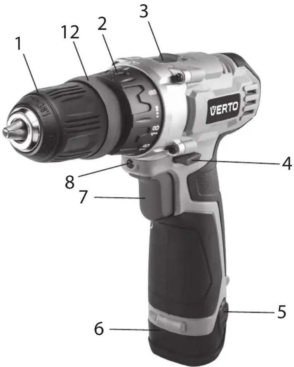
Below enumeration refers to the device elements depicted on the drawing pages of this manual.
- Quick-release chuck
- Torque adjustment ring
- Gear switch
- Direction selector switch
- Battery lock button
- Battery
- Switch
- Illumination
VERTO
-
Charging station
-
Charger
- LED
- Locking ring
- Spindle
* Differences may appear between the product and drawing.
MEANING OF SYMBOLS


CAUTION
WARNING
ASSEMBLY / SETTINGS
INFORMATION
EQUIPMENT AND ACCESSORIES
- Battery - 2 pcs
- Charger - 1 pce
- Charging station - 1 pce
REMOVING AND INSERTING THE BATTERY

- Set the direction selector switch (4) in middle position.
- Push battery lock buttons (5) and slide out the battery (6) (fig. A).
- Insert charged battery (6) into the handle holder, you should hear when the battery lock buttons (5) snap.
BATTERY CHARGING

Drill is supplied with partially charged battery. The battery should be charged in ambient temperature between 4°C and 40°C. New battery, or one that has not been used for a long time, will reach full efficiency after approximately 3 to 5 charge/discharge cycles.

- Remove the battery (6) from the drill (fig. A).
- Connect the charger (10) to a mains socket (230 V AC).
- Connect the charging station (9) to the charger (10).
- Put the battery (6) into the charging station (9) (fig. B).

- Once the charger (10) has been connected to mains green LED will light up (11), signalling presence of charging voltage.
- When the battery (6) is placed in charging station (9) red LED lights up (11), which indicates that the battery charging is in progress (fig. B).
- Green LED (11) turns on again when the battery is fully charged (after 5 hours) or battery temperature is too high (above 45°C).

When the battery reaches too high temperature during charging (above 45^ C) charging is interrupted. Charging resumes automatically when the battery cools down. This temperature rise inside the battery is not likely and may never occur. Each time the battery is removed and inserted into charging station during recharge, the charging cycle resets regardless of the current battery level.

Batteries heat up strongly when charging. Do not operate just after charging – wait for the battery to cool down to room temperature. It will prevent battery damage.
SPINDLE BRAKE

Drill is equipped with electronic brake that stops the spindle immediately after the switch button (7) is released. The brake ensures precision when screwing or drilling and prevents free spindle rotation after switching off.
Switching off – release the switch button (7).

Each time the switch button (7) is pressed, the LED diode (8) lights up to illuminate the workplace.
ROTATIONAL SPEED CONTROL

Increase or reduce pressure on the switch button (7) to adjust drilling or driving speed while operating. Speed adjustment allows for a soft start, which prevents dill slipping when drilling holes in gypsum or glaze, and allows for operation control when driving screws in and out.
OVERLOAD CLUTCH

Set the torque adjustment ring (2) in appropriate position to permanently set overload clutch to defined torque value. When the set torque is reached, overload clutch disconnects automatically. It prevents from driving screws too deep or damaging the drill.
TORQUE ADJUSTMENT

- Different screws and materials require different torque to be applied.
- The bigger the number corresponding to given position, the bigger is the torque (fig. C).
- Set the torque adjustment ring (2) to appropriate torque value.
• Always start operation with low torque. - Increase the torque gradually until obtaining desired results.
- Use higher settings to undo screws.
- When drilling, choose setting marked with the drill symbol. The torque is the greatest with this setting.
- Knowledge how to choose appropriate torque setting comes with practice.

Setting the torque adjustment ring in the drilling position deactivates the overload clutch.
INSTALLATION OF WORKING TOOL IN THE DRILL CHUCK

- Set the direction selector switch (4) in the middle position.
- Turn the ring of the quick release chuck (1) counter clockwise (see mark on the ring) to spread jaws enough to insert drill or driver bit (fig. D).
• To fix the working tool, turn the ring of the quick release chuck (1) clockwise and tighten.

Deinstallation of the tool is similar to installation, only the sequence of actions is reversed.

Make sure the tool position is correct when installing drill or driver bit in the quick release chuck. Use additional magnetic adapter as an extension when using short driver bits.
DRILL CHUCK INSTALLATION AND REMOVAL

- Pull the locking ring (12) forward and slide the drill chuck (1) off the spindle (fig. E).
- Installation of the drill chuck (1) is similar to removal, only the sequence of actions is reversed.
- Pull the locking ring (12) away and slide the drill chuck (1) onto the spindle until you can clearly hear the lock snaps in (it may be necessary to rotate the drill chuck slightly so it can reach appropriate position).
INSTALLATION AND REPLACEMENT OF WORKING TOOLS IN THE SPINDLE HOLDER

- Place appropriate working bit directly in the spindle holder (13) (fig. F). - Ensure the bit is inserted to the end and is properly installed. - To remove the working tool, pull the working bit out of the spindle holder.

Use additional driver bit adapter with short driver bits. It is recommended to always make a pilot hole before screwing screws with the screwdriver. When a short driver bit is installed in the spindle, it is not necessary to remove it when installing the drill chuck (fig. G).
RIGHT-LEFT DIRECTION OF ROTATION

Choose direction of spindle rotation with the direction selector switch (4) (fig. H).
Clockwise rotation - set the switch (4) to the extreme left position.
Counter-clockwise rotation - set the switch (4) to the extreme right position.
* In certain cases position of the switch related to rotation may be different than specified. Please refer to graphic signs located on the switch or tool body.

Safe position of the direction selector switch (4) is in the middle, it prevents accidental starting of the power tool.
- Drill cannot be started, when the switch is in this position.
- Use this position of the switch to change drills or bits.
- Before starting the tool make sure the position of the direction selector switch (4) is correct.

Do not change direction of rotation when the drill spindle is rotating.
CHANGE OF GEAR

The gear switch (3) (fig. 1) allows to increase the rotational speed range.
Gear I: small speed range, big torque
Gear II: greater speed range, smaller torque.
Set the gear switch in position appropriate for the works to perform. When the switch is blocked and cannot be moved, turn the spindle slightly.

Never change the gear switch position when the drill is operating. It may damage the power tool.

Long lasting drilling at low rotational speed of the spindle may cause motor overheating. Make periodic breaks in operation or allow the tool to operate at top speed without load for approximately 3 minutes.
- Cleaning the device after each use is recommended.
- Do not use water or any other liquid for cleaning.
- Clean the drill with a dry cloth or blow with compressed air at low pressure.
- Do not use any cleaning agents or solvents, they may damage plastic parts.
-
Clean ventilation holes in the motor casing regularly to prevent device overheating.
-
Store the drill in a dry place, beyond reach of children.
- Store the device with the battery removed.
All defects should be repaired by service workshop authorized by the manufacturer.
TECHNICAL PARAMETERS
RATED PARAMETERS
| Cordless Drill 50G273 | |
| Parameter Value | |
| Battery voltage 10,8 V DC | |
| Battery type Li-ion | |
| Battery capacity 1300 mAh | |
| Range of idle rotational speed | 0-350 / 0-1350 min ^-1 |
| Chuck range 0,8-10 mm | |
| Torque control range 1 – 18 plus drilling | |
| Max. torque (soft drive) 19 Nm | |
| Max. torque (hard drive) 35 Nm | |
| Protection class III | |
| Weight, drill with battery 1,1 kg | |
| Year of production 2020 | |
| 50G273 defines type and indication of the device | |
| Charger | |
| Parameter Value | |
| Supply voltage | 230 V AC |
| Power supply frequency | 50 Hz |
| Charging voltage | 13,5 V DC |
| Max. charging current | 350 mA |
| Battery charging time | 3-5 h |
| Protection class | II |
| Weight | 0,07 kg |
| Year of production 2020 | |
NOISE LEVEL AND VIBRATION PARAMETERS
| Sound pressure | Lp_A = 67dB (A) K=3dB (A) |
| Sound power | Lw_A = 78 dB (A) K=3dB (A) |
| Vibration acceleration | a_h = 1,9 m/s^2 K=1,5 m/s^2 |

Noise and vibration information
Noise produced by the device is defined with: level of produced sound pressure Lp_A and level of sound power Lw_A (where K is measurement uncertainty). Vibrations produced by the device are defined with vibration acceleration value a_h (where K is measurement uncertainty).
Sound pressure Lp_N sound power Lw_A and vibration acceleration a_h specified in this manual have been measured in accordance with EN 60745. Specified vibration level a_h can be used to compare tools and for initial evaluation of exposition to vibrations.
VERTO
Specified vibration level is representative only for main applications of the device. When the device is used for other purposes or with different working tools, the vibration level may change. Insufficient or too rare maintenance may increase vibration level. The abovementioned factors may lead to higher exposure to vibrations during whole working time.
In order to precisely define exposure to vibrations, include periods when the device is switched off and when it is switched on but not used for working. Once all factors have been carefully considered, total exposition to vibrations may be significantly lower.
To protect the user from results of exposure to vibrations, use additional safety measures such as: device and working tool periodic maintenance, proper hand temperature conditions, good work organisation.
ENVIRONMENT PROTECTION
Do not dispose of electrically powered products with household wastes, they should be utilized in proper plants. Obtain information on waste utilization from your seller or local authorities. Used up electric and electronic equipment contains substances active in natural environment. Unrecycled equipment constitutes a potential risk for environment and human health.
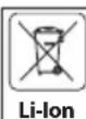
The storage batteries/batteries must not be disposed with domestic waste, put in a fire or into the water. Damaged or used up storage batteries must be properly recycled in compliance with the current directive pertaining to disposal of storage batteries and batteries.
* Right to introduce changes is reserved.
"Grupa Topex Spółka z ograniczoną odpowiedzialnością" Spółka komandytowa with seat in Warsaw at ul. Pograniczna 2/4 (hereinafter Grupa Topex) informs, that all copyrights to this instruction (hereinafter Instruction), including, but not limited to, text, photographies, schemes, drawings and layout of the instruction, belong to Grupa Topex exclusively and are protected by laws accordingly to Copyright and Related Rights Act of 4 February 2004 (ustawa o prawie autorskim i prawach pokrewnych, Dz. U. 2006 No 90 item 631 with later amendments). Copying, processing, publishing, modifications for commercial purposes of the entire Instruction or its parts without written permission of Grupa Topex are strictly forbidden and may cause civil and legal liability.

DODATNA PRAVILA ZA VARNO UPORABO
VRTALNIKA-VIJAČNIKA
GRAFISKÄS DALAS APRAKSTS
DARBVÄRPSTAS BREMZES

LAADIJA ERIOUTUSJUHISED
POSEBNI PROPISI O SIGURNOSTI
POSEBNI PROPISI VEZANI ZA SIGURAN RAD BUŠILICOM-IZVIJAČEM
- Koristite štitnike sluha za vrijeme rada s bušilicomizvijačem. Ako se izlažete buci, to može dovesti do gubitka sluha. Metalna piljevina i druge leteće čestice mogu trajno oštetiti vid.
- Alat koristite s dodatnim drškama koje su s njim dostavljene. Gubitak kontrole može dovesti do osobnih povreda radnika.
DODATNA SIGURNOSNA PRAVILA RADA
BUŠILICOM-IZVIJAČEM
PRIBOR I DODATNA OPREMA
-
Aku-baterija - 2 kom.
-
Punjač - 1 kom.
-
Stanica za punjenje - 1 kom.
PRIPREMA ZA RAD
VAĐENJE / STAVLJANJE AKU-BATERIJE

PROTUOPTEREĆUJUĆA SPOJKA

Postavljanje prstena za regulaciju okretnog momenta (2) u odgovarajući položaj uzrokuje trajno namještanje spojke na određenu veličinu okretnog momenta. Nakon postizanja postavljene brzine okretnog momenta automatski dolazi do isključivanja protuopterećujuće spojke. To će pomoći pri zaštiti od zavijanja vijka preduboko odnosno od oštećenja bušilice-izvijača.
REGULACIJA OKRETNOG MOMENTA

- Za različite vijke i različite materijale koristite razne veličine momenta.
- Moment je tim veći, čim je veći broj koji odgovora tom položaju (crtež C).
- Podesite prsten za regulaciju okretnog momenta (2) na određenu veličinu okretnog momenta.
- Uvijek počnite raditi od momenta niže vrijednosti.
- Postepeno povećavajte moment, sve dok ne postignete zadovoljavajući rezultat.
- Za odvijanje vijaka odaberite više postavke.
- Za bušenje treba odabrati postavke označene simbolima svrdla. Kod tih postavki postiže se najbolja vrijednost okretnog momenta.
VERTO
