
Aquarea PAW-TD23B6E5 - Water heater PANASONIC - Free user manual and instructions
Find the device manual for free Aquarea PAW-TD23B6E5 PANASONIC in PDF.

| Product type | Storage water heater "tank-in-tank" |
| Brand | Panasonic |
| Model | Aquarea PAW-TD23B6E5 |
| Dimensions (H x W x D) | 1751 x 599 x 646 mm |
| Empty / filled weight | 111 kg / 401 kg |
| DHW / buffer volume | 230 L / 60 L |
| Electrical supply | 230 V ~ 50 Hz, single-phase |
| Backup heating element power | 2.8 kW |
| Max. operating pressure (DHW) | 1.0 MPa (10 bar) |
| Max. operating pressure (buffer) | 0.3 MPa (3 bar) |
| Max. operating temperature | 80 °C |
| Insulation (material/thickness) | PUR 4th generation / 50 mm |
| Static heat loss (DHW/buffer) | 52 W / 29 W |
| Energy loss at 65 °C (DHW/buffer) | 1.25 / 0.7 kWh/24 h |
| ERP class (DHW/buffer) | B / A |
| Reservoir material | Stainless steel EN 1.4521 |
| Connections | DHW: Ø22 mm, buffer: Ø22 mm, valve: 3/4" |
| Main functions | DHW production, radiator/underfloor heating, compatible with air/water heat pump |
| Regular maintenance | Check pressure gauge (2x/year), operate safety valve (1x/year), check anode (if present) |
| Safety devices | Thermal and pressure relief valve, overheat protection (85°C), TSR thermostat |
| Spare parts available | Yes: anode, heating element, pump, valve, etc. |
| Warranty | 2 years |
Frequently Asked Questions - Aquarea PAW-TD23B6E5 PANASONIC
User questions about Aquarea PAW-TD23B6E5 PANASONIC
0 question about this device. Answer the ones you know or ask your own.
Ask a new question about this device
Download the instructions for your Water heater in PDF format for free! Find your manual Aquarea PAW-TD23B6E5 - PANASONIC and take your electronic device back in hand. On this page are published all the documents necessary for the use of your device. Aquarea PAW-TD23B6E5 by PANASONIC.
USER MANUAL Aquarea PAW-TD23B6E5 PANASONIC
Languages in manual:
| EN - English | HU - Hungary |
| BG - Bulgarian | IT - Italian |
| CS - Czech | LV - Latvian |
| DA - Danish | NL - Dutch |
| DE - German | NO - Norwegian |
| EE - Estonian | PL - Polish |
| ES - Spanish | PT - Portugese |
| FI - Finnish | RO - Romanian |
| FR - French | SK - Slovenian |
| GR - Greek | SV - Swedish |
| HR - Croatian | TR - Turkish |
SAFETY INFORMATION
INSTALLATION MANUAL
OPERATING INSTRUCTIONS
TDS - TECHNICAL DATA SHEET

natural_image
Technical line drawing of a rectangular industrial or mechanical enclosure with internal components and no visible text or symbols.CONTENTS
1. Safety instructions .... 3
1.1 General information 3
1.2 Safety instructions for users 4
1.3 Safety instructions for installers 4
2. Product description 5
2.1. Product identification 5
2.2. Intended use 5
2.3 CE marking 5
2.4 Technical data 5
2.5. ErP data (TDS).... 5
3. Installation instructions 6
3.1. Products covered by these instructions 6
3.2. Included in delivery 6
3.3. Product dimensions 6
3.4. Requirements for installation location 7
3.5. Pipe installation 8
3.6. Electrical installation.... 10
4. Maintenance and draining.... 12
4.1. Checking the manometer 12
4.2. Checking the safety valve.... 12
4.3. Checking the protective anode.... 12
4.4 Draining the product 12
5. Spare parts.... 13
5.1. Spare parts list 13
6. Warranty conditions.... 14
6.1. Warranty conditions 14
7. Recycling and handover 15
7.1 Disposal 15
7.2 Handover to end-user 15
7.3 Installer/electrician contact information ....15
Dear customer
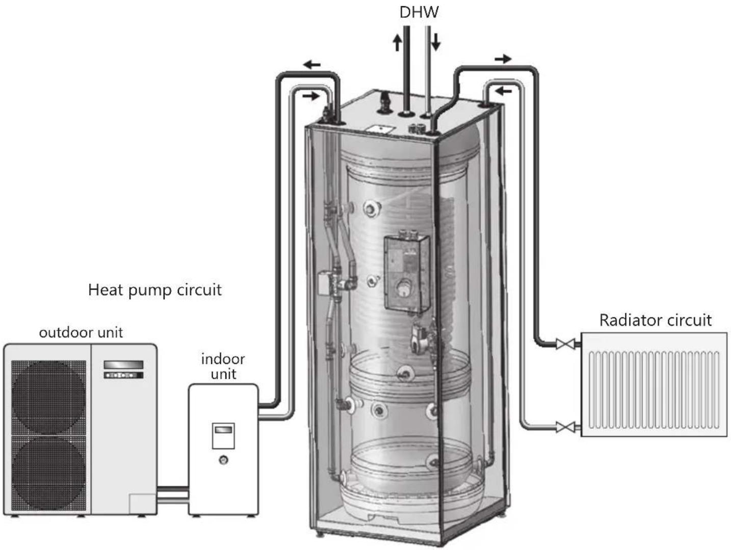
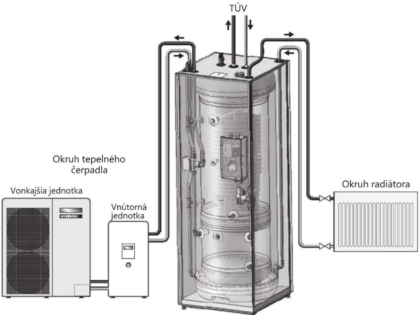
PAW-TD23B6E5 is a high-grade stainless steel tank-in-tank unit with high performance and very low heat losses, intended to supply the household with domestic hot water and heating to radiators / underfloor heating.
The unit is insulated with 50 mm. of 4th gen. PUR insulation material, reducing heat losses to a minimum. The 230L domestic hot water tank with a built-in large heating coil will supply sufficient hot water for a normal household, while the 60L buffer tank reduces the number of start and stop sequences for the air/water heat pump. This increases the heat pump lifespan, energy efficiency and provides greater comfort. The tank-in-tank technology also reduces the total footprint of the system.
1. SAFETY INSTRUCTIONS
1.1 General information
- Read the following safety instructions carefully before installing, maintaining or adjusting the water heater.
- Personal injury or material damage may result if the product is not installed or used in the intended manner.
- Keep this manual and other relevant documents where they are accessible for future reference.
- The manufacturer assumes compliance (by the end-user) with the safety, operating and maintenance instructions supplied and (by the installer) with the fitting manual and relevant standards and regulations in effect at the date of installation.
natural_image
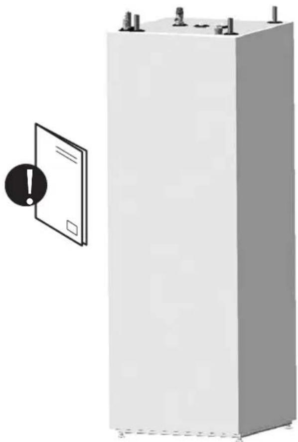
Illustration of a large industrial battery with warning symbol and warning label (no text or symbols on main body)Symbols used in this manual:
| ⚠ WARNING | Could cause serious injury or death |
| ⚠ CAUTION | Could cause minor or moderate injury or damage to property |
| ∅ | DO NOT |
| ! | DO |
| ⚠️ CAUTION |
| Incorrect repairs may lead to danger for users. Only trained and qualified technicians are authorised to install, move, modify or repair this product. |
| The warranty does not apply if the applicable regulations are not complied with. |
| The tank must not be stored outdoors before installation. |
| Always wear gloves during installation or repair. Touching the pipes may lead to hot or cold burns. |

This document should be kept in a suitable place where it is accessible for future reference.
1.2 Safety instructions for users
| ⚠ WARNING | |
| ∅ | The overflow from the Temperature & Pressure relief valve must NOT be sealed or plugged. |
| ∅ | The product must NOT be covered. Do NOT place foreign objects near or on the product. |
| ∅ | The product must NOT be modified or changed from its original state. |
| ∅ | Children must NOT play with the product or go near it without supervision. |
| ! | The product should be filled with water before the power is switched on. |
| ! | Maintenance/settings should only be carried out by persons over 18 years of age, with sufficient understanding. |
| ⚠️ CAUTION | |
| ∅ | The product must not be exposed to frost, over-pressure, over-voltage or chlorine treatment. See warranty conditions. |
| ∅ | Maintenance/settings should not be carried out by persons of diminished physical or mental capacity, unless they have been instructed in the correct use by someone responsible for their safety. |
1.3 Safety instructions for installers
| ⚠ WARNING | |
| ∅ | The overflow from the Temperature & Pressure relief valve must NOT be sealed or plugged. |
| ! | Any overflow pipe from the safety valve must be installed uninterruptable and frost-free with a fall to the drain/gully. |
| ! | The electrical wiring diagram in this manual must be followed. No optional wiring is allowed. All work on electrical systems must be performed by an authorized installer. |
| ! | The mains cable should withstand 90°C. A strain reliever must be fitted. |
| ! | The product must be filled with water before the power is switched on. |
| ! | The relevant regulations and standards, and this installation manual, must be followed. |
| ! | For the buffer tank - a closed pressurized system of installation - it is obligatory to install a safety valve with a rated pressure of max. 0.3 MPa (3 bar), which prevents the elevation of pressure in the buffer tank by more than 0.1 MPa (1 bar) above the rated pressure. This safety valve must be supplied and installed separately, and is not part of this product. To ensure proper functioning of the safety valve, annual control to remove any blockage of the outlet shall be performed. |
| ⚠️ CAUTION | |
| 💡 | The product should be placed in a room with a drain. |
| 💡 | The product should be properly aligned vertically and horizontally, on a floor surface suitable for the total weight of the product when in operation. See table 2.4. |
| 💡 | The product must have a service clearance of 120 cm in front of the cover / 50 cm on top. |
2. PRODUCT DESCRIPTION
2.1 Product identification
Identification details can be found on the type plate fixed to the product. It contains product information and other useful data.
The product is designed and manufactured in accordance with:
• Safety standard EN 60335-1
• Safety standard EN 60335-2-21
• Welding standard EN ISO 3834-2
• Pressure vessel standard EN 12897
2.2 Intended use
The product is designed to supply domestic hot water in combination with a central heating and cooling system. The product has been designed to be connected to an external heat pump.
2.3 CE marking
CE
The CE mark shows that the product complies with the relevant Directives. See Declaration of Conformity at the manufacturers' website for more information.
The product complies with EU directives:
- Low voltage LVD 2014/35/EU
• Electromagnetic compatibility EMC 2014/30/EU - Pressurised equipment PED 2014/68/EU
Any safety valve(s) used in the system shall be CE-marked and comply with PED 2014/68/EU.
2.4 Technical data
| Parameter Unit Description | ||
| Measures HxWxD mm 1751x599x6 | 46 | |
| Weight (empty) kg 111 | ||
| Weight (full) | kg 401 | |
| Volume | litres DHW+Buffer | 230+60 |
| Electric element - effect | kW | 2.8 |
| Power supply | V / Phase / Hz | 230 / 1 / 50 |
| Domestic hot water tank: | ||
| Volume | litres | 230 |
| Max working pressure | MPa (bar) | 1,0 (10) |
| Pressure test (bar) | MPa (bar) | 1,5 (15) |
| Max working temp | °C | 80 |
| Connections / Material | mm / EN | 22 / 1.4404 |
| Tank material | EN 1.4521 | |
| Insulation | Material/thickness | PUR / 50 |
| Heating coil surface | m2 1.8 | |
| Energy loss at 65°C | kWh/24h | 1,25 / 0,7 |
| Buffer tank: | ||
| Volume | litres | 60 |
| Max working pressure | MPa (bar) | 0,3 (3,0) |
| Pressure test | MPa (bar) | 0,39 (3.9) |
| Max working temp | °C | 80 |
| Connections / Material | mm / EN | 22 , copper |
| Tank material | EN 1.4521 | |
| Insulation | Material/thickness | PUR / 50 |
2.5 ErP data - Technical Data Sheet
| Brand | Model name | ErP rating DHW tank | ErP rating buffer tank | Standing heat loss DHW tank | Standing heat loss buffer tank | Storage vol. ltr. DHW tank | Storage vol. ltr. buffer tank | |
| OSO | PAW-TD23B6E5 | B | A | 52 | 29 | 230 | 60 | |
| Directive: 2010/30/EU Regulation: EU 812/2013 | Directive: 2009/125/EC Regulation: EU 814/2013 | |||||||
| Heat loss tested according to standard: EN 12897:2016 | ||||||||
3. INSTALLATION INSTRUCTIONS
3.1 Products covered by these instructions
80341990 PAW-TD23B6E5
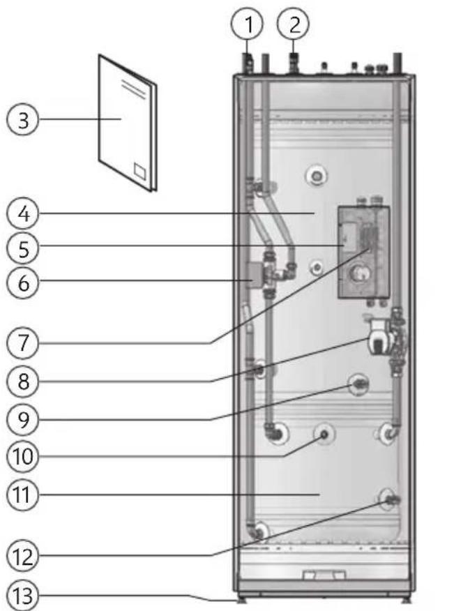
3.2 Included in delivery
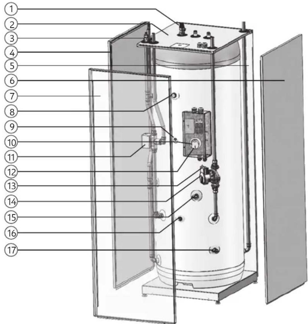
| Ref no. | Pcs. | Description |
| 1 | 1 | Air vent valve for DHW tank |
| 2 | 1 | Temperature and pressure valve (T&P) |
| 3 | 1 | Installation manual (this document) |
| 4 | 1 | DHW tank, 230L, max pressure 10.0 bar |
| 5 | 1 | Electronic box |
| 6 | 1 | 3-way valve |
| 7 | 1 | Terminal block |
| 8 | 1 | Circulation pump |
| 9 | 1 | Drain valve for DHW tank |
| 10 | 1 | Air vent valve for buffer tank |
| 11 | 1 | Buffer tank, 60L, max pressure 3.0 bar |
| 12 | 1 | Drain valve for buffer tank |
| 13 | 4 | Adjustable feet |
3.3 Product dimensions
All dimensions in mm.
| Product. | A | B | C | D | E | F | |||
| NDS | 17 | -37 | 175 | 51 | 1853 | 646 | 599 |
Tolerance +/- 5 mm. (not dimension A).
3.3.1 Important notice before installation
Make sure you've chosen a heat pump that suits existing heating system and power equipment. The product must also suit the nominal water flow, lift height and size of the system. Only use clean water in the tank. If the water quality is poor the tank may be damaged. There is also a risk of corrosion and clogging if the water quality is not maintained. The water quality must not exceed these values:
Chloride content < 100 mg/l
Total Dissolved Solids < 200 mg/l
pH level > 6.0 / < 9.5
Should the water quality exceed the above parameters, a sacrificial anode may be installed in the plugged G3/4" internal connection in the DHW tank. The anode must be in compliance with local regulations, and fitted by an authorized installer before the system has been filled with water. When the sacrificial anode is installed, the water quality must not exceed these values:
Chloride content < 250 mg/l
Total Dissolved Solids < 500 mg/l
pH level > 6.0 / < 9.5

3.3.2 Pipe connections and valves
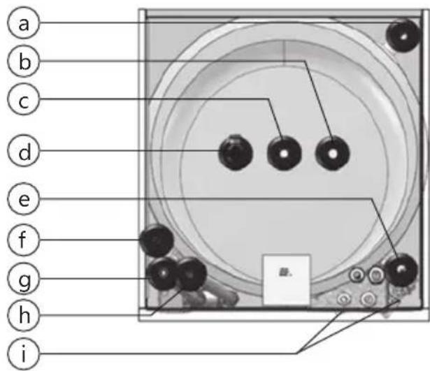
| Ref. Dim. Description |
| a ø22 Radiator circuit return |
| b ø22 Domestic cold water in |
| c ø22 Domestic hot water out |
| d 3/4" Temperature and pressure valve (T&P) |
| e ø22 Radiator circuit flow |
| f ø22 Heat pump circuit flow |
| g 1/8" Air vent valve for heating system |
| h ø22 Heat pump circuit return |
| i DN15 Drain valves (DHW tank & buffer tank) |
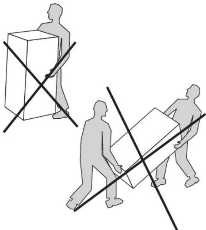
3.3.3 Transport and unpacking
The product should be transported carefully, with packaging. Also please note:
- The product is very heavy and should not be lifted by one person alone.
- Do not transport the unit horizontal. This can cause damage or failure.
• To avoid hand injury, wear gloves when moving the product and/or while removing the packaging. - Be careful not to damage the product while removing the packaging.
- To avoid damage an installed tank must be drained before moving.
| ⚠️ CAUTION |
| Pipe stubs, valves etc. should not be used to lift the product as this could cause malfunctions. |
3.4 Requirements for installation, location and positioning
natural_image
Illustration of two human figures carrying boxes with diagonal lines, no text or symbols present| ⚠️ CAUTION | |
| 💡 | The product shall be placed in a room with a drain to avoid any damages in case of water escaping from the product. |
| 💡 | The product must be placed in an area that is dry, clean, free of vapour, volatile oils, smoke and gases to avoid any damages to internal parts of the product. |
| 💡 | The product shall be placed in a dry and permanently frost-free position. |
| 💡 | The product shall be placed on a floor surface suitable for the total weight of the product when in operation. See product data plate. |
| 💡 | Install the tank unit as close to the heat pump as possible. This limits the necessary volume of coolant (due to pipe length). |
| 💡 | The product must have a service clearance of 120 cm in front of the cover / 50 cm on top. |
| 💡 | The product shall be easily accessible in the home for servicing and maintenance. |
3.5 Pipe installation
The domestic hot water tank (upper) is designed to be permanently connected to the mains water supply. The buffer tank (lower) is designed to be permanently connected to the heating system, with max. pressure 3 bar / 0.3 MPa. A separate safety valve with rated opening pressure max. 3.0 bar must be installed in the heating system. Approved pipes of the correct size should be used for installation. The relevant standards and regulations must be followed.
3.5.1 Heating and domestic hot water
Use connectors that reduce transfer of vibration, and can withstand the water temperature and pressure. To avoid "taps" in the heating system, the pipes must be able to withstand temperature differences.
3.5.2 Pipe connection dimensions
| Cold water inlet | Hot water outlet | HP flow | HP return | Rad. flow | Rad. return | Drain |
| 22 22 | 22 22 | 22 22 | DN15 |
3.5.3 Pipe installation procedure
-
Place the unit in the desired position. Adjust unit to a level position by using the adjustable feet. The tank must be levelled before it is connected and filled with water. Remove front cover, see pt. 3.5.4.
-
Flush/clean the existing heating system carefully to avoid contaminating the particle filter.
-
Connect the domestic water supply. A mixing valve is recommended to avoid scalding.
-
Connect the unit supply and return pipes to the existing heating system. The various pipes are marked on the top of the tank.
-
Connect an escape pipe and tundish between the Temperature & Pressure relief valve and the floor drain.
-
Connect an escape pipe between the radiator safety valve and the floor drain.
-
Verify if the expansion vessel is dimensioned for the heating system (approx. 10% of the total volume in the system.)
-
Check the re-pressure of the expansion vessel. The pressure depends on how high the water has to be lifted.
-
Fill the domestic hot water tank before filling the buffer tank. Open a hot water tap to ventilate and allow free flow of water.
-
Put the 3-way valve manually in "fill mode" (both flow way open) and open the manual / automatic air vent.
-
Fill the radiator system and close the manual air vent.
-
Keep the pressure within the recommended pressure range to prevent the water escaping through the safety valve. Restore the 3-way valve in automatic position.
-
Bleed the radiators. Check the system pressure. Fill more water to the system if needed. Repeat until all air is bled from the system.
-
Check if the diverting valve switches to radiator operation and that the radiators heat up. Bleed the system once it is warm. Check for leaks in the system.
-
Close the automatic air vent after approx. two weeks to prevent air from entering the system.
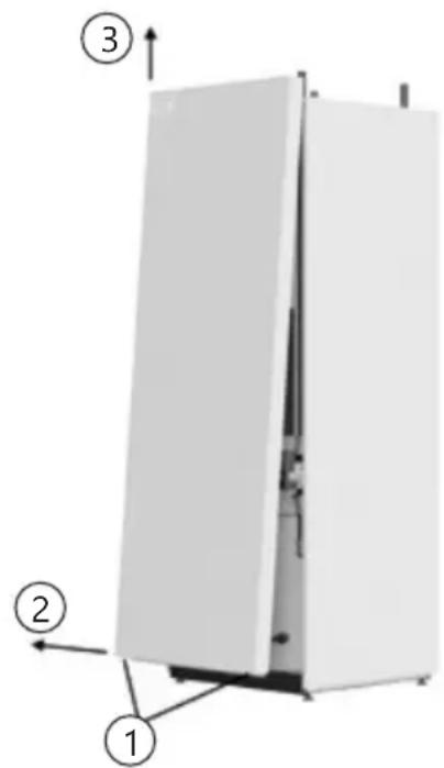
3.5.4 Removing the front cover
-
Unscrew and remove the two screws in the lower part of the front panel (1).
-
Pull out the lower part of the front approx. 100-150mm. (2).
-
Grip the sides of the front panel and lift it straight up (3).
-
Remove the front panel carefully to not damage the contact or the cable connection between the display and the control unit inside the front panel.
3.5.5 Pipe connection layout
3.5.6 Fitting instructions
| ⚠ WARNING | |
| 💡 | The product must be filled with water before the power is switched on. |
| 💡 | Any overflow pipe from the T&P valve must be installed uninterruptable and frost-free with a continuous fall to the drain/gully. |
| CAUTION | |
| ! | The product should be placed in a room with a drain to avoid any damages in case of water escaping from the product. |
| ! | The product should be placed on a floor surface suitable for the total weight of the product when in operation. See product data plate. |
| ! | The product must have a service clearance of 120 cm in front of the cover / 50 cm on top. |
3.5.7 Installation recommendation
| RECOMMENDATION | |
| - | Allow clearance to the floor for venting purposes. Screw the feet out a minimum of 15 mm from the bottom of the product. |
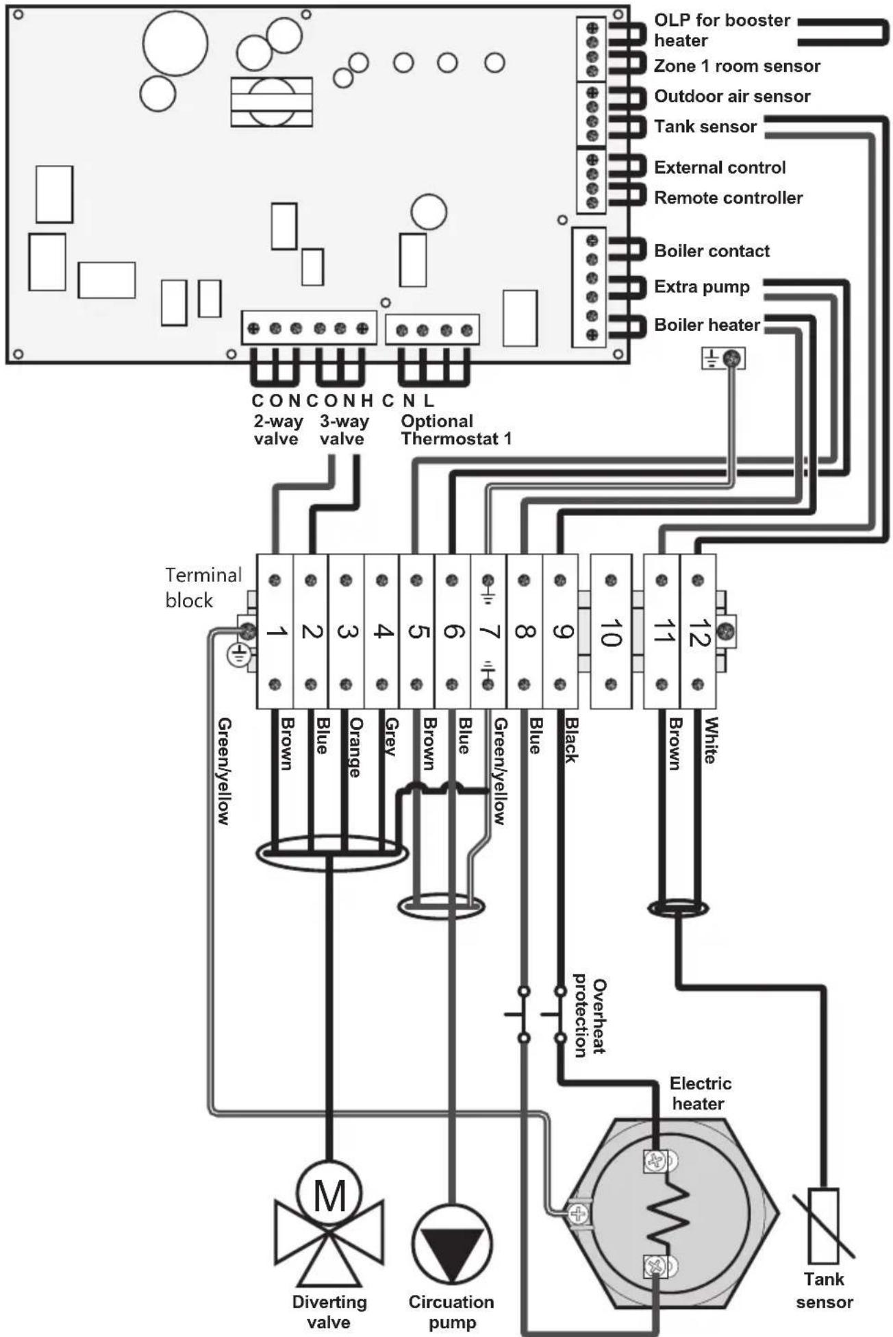
3.6 Electrical installation
Fixed electric fittings should be used for installation. Any fixed electric fittings must be installed by an authorised electrician. The relevant standards and regulations must be followed.
Wiring: Connect the corresponding wires from the hydrobox into the electronic box inside the tank unit according to pt. 3.6.4. OLP for Booster Heater at the HP must be jumpered.
3.6.1 Backup immersion heater thermostat
The immersion heater is designed as an auxiliary backup heat source. Power to the immersion heater must not be switched on until the unit is filled with water. The unit is fitted with one 2.8 kW immersion heater which is located in the electrical box, see pt. 5.1.
Alternative thermostats must not be used. Follow the wiring instructions (right) connecting the live (L), neutral (N) and earth cables as indicated.
The heater must be connected to a minimum 16 amp dedicated permanent supply complying with current local wiring regulations, isolation is required via a minimum 20 amp double pole isolation switch with a minimum 3 mm separation required.
All electrical wiring should be carried out by a competent electrician, using a heat resistant cable (minimum 85°C), and be in accordance with the latest local Wiring Regulations. The TSR thermostat functions solely as a safety cut-out and will operate at 85°C (±5°C). Should this happen, check reasons for thermal cut-out button being released and when satisfied press the reset button (R).
3.6.2 Replacing the safety cut.out thermostat Disconnect power supply. Disconnect power cables
(L) and (N) from the thermostat by loosening screw A and B. Pull thermostat straight out of the element. Fit the replacement thermostat by inserting the temperature sensor (D) into the tube (E). Push thermostat connectors firmly into the connector receptors (C) and make sure the connectors are inserted fully into the receptors. Refit power cables (L) and (N), tighten screws A and B to 2 Nm (+/- 0.1).
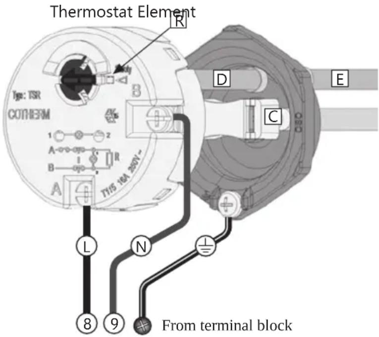
| WARNING |
| Constant voltage present in electronic box. Before any electrical work is done, the power supply must be disconnected and secured against activation while the work is in progress. |
| The thermostat must never be dismantled/opened. This will compromise its function and cause risk of overheating. Warranty will cease. |
3.6.3 Fitting instructions
| ⚠ WARNING | |
| 💡 | The product must be filled with water before the power is switched on. |
| 💡 | Any fixed electric fittings must be installed by an authorised electrician. The relevant standards and regulations must be followed. |
| 💡 | The mains cable should withstand 90°C. A strain reliever must be fitted. |
| ⚠️ CAUTION | |
| #! | The product must have a service clearance of 120 cm in front of the cover / 50 cm on top. |
| #! | In case of damage to the mains cable, it should be replaced with a suitable mains cable from the manufacturer. |
3.6.4 Electrical wiring diagram - main PCB of Heat Pump (Aquarea H and J series)
4.MAINTENANCE AND DRAINING
Maintenance should be carried out by persons over 18 years of age, with sufficient understanding. If in doubt, contact authorized installer.
4.1 Checking the manometer
Check manometer 2 times/year. It is particularly important to check the manometer after a new installation. The manometer showing the pressure within the radiator system should display between 0.5 – 1.2 bar. If needed, fill the system with water until the manometer shows 1.0 bar. If you feel uncertain contact your installer.
4.2 Checking the temperature & pressure relief valve
Exercise the T&P relief valve once every year by turning its wheel until water is streaming out of the valve. The test is performed to safeguard the function of the valve.
The temperature variations within the system make the water expand, which may lead to water occasionally dripping out of the overflow pipe. This is normal and no action is necessary.
⚠ WARNING
The overflow from the T&P safety valve must NOT be blocked, sealed or plugged.
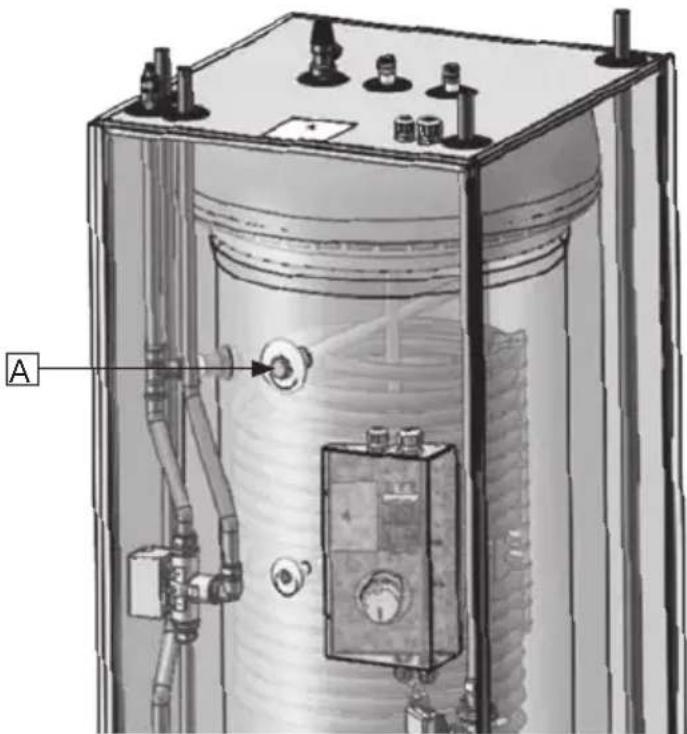
4.3 Checking the protective anode (if installed)
- Shut the system down using the on/off button on the control panel. Switch control fuse off.
- Turn off the cold water supply to the tank.
- De-pressurize the buffer tank to less than 0.5 bar.
- Open a domestic hot water tap to release pressure from the tank. Leave open.
- Open the drain valve for the DHW tank. The product will drain.
- Unscrew, pull out and clean the anode (A).
- Measure the diameter. If the diameter of the anode is less than 10 mm it must be replaced.
- Refit the anode with torque 40Nm.
- Close the domestic hot water tap.
-
Open incoming cold water supply to the tank.
-
Re-pressurize the buffer tank to previous setting.
- Restart the system by turning the control fuse on and push the on/off button on the unit control panel.
natural_image
Technical diagram of a cylindrical industrial or gas storage unit with internal components and piping (no text or symbols visible)⚠ WARNING
Replace the anode if the diameter is less than 10 mm. The anode protects the tank from aggressive chemical substances in the water.
4.4 Draining the product
- Shut the system down using the on/off button on the control panel. Switch control fuse off.
- Turn off the cold water supply to the tank.
- De-pressurize the buffer tank to less than 0.5 bar.
- Open a domestic hot water tap to release pressure from the tank. Leave open.
- Open the drain valve for the DHW tank. The product will drain.
To refill the product see pt. 3.5.3.
5. SPARE PARTS
5.1 Spare parts list
| Pos No. | Article no. | Part name Description | |
| 1 | 920 | 20 | Temperature & Pressure relief G1/2Mx15mm., Reliance TPR 15, 10 bar/90-95°C |
| 2 | 18-6041 | Cover panel Top | |
| 3 | 1-1011 | Air vent valve heating circuit G1/8M, ø2 mm. vent | |
| 4 | 18-6124 | Cover panel Left/right side | |
| 5 | 18-6160 | Cover panel Rear side | |
| 6 | 18-6124 | Cover panel Left/right side | |
| 7 | 18-6099 | Cover panel Front | |
| 8 | 56029 | Optional 3/4" anode G3/4M, Al rod, L480 mm. | |
| 9 | 1-1099 | Sensor /Thermistor ø8 mm., including wire 1.5 m. | |
| 10 | 80313 | El. overheat protection Cotherm TSR 00037, 85°C | |
| 11 | 1-4045 | 3 way valve G1M, Honeywell SPDT, V4044F1034 | |
| 12 | 71252 | El. heating element G 5/4M, 2800W / 1x230V, INC825/CW625N | |
| 13 | 1-1199 | Electric cable connection, pump Electric cable for Wilo Yonos Para circ. pump | |
| 14 | 1-10053 | Circulation pump | Wilo Yonos Para 25-130/7-5 |
| 15 | 1-1007 | Drain valve DHW tank | G1/2M, ø7 mm. drain |
| 16 | 1-1011 | Air vent valve buffer tank | G1/8M, ø2 mm. vent |
| 17 | 1-1007 | Drain valve buffer tank G1/2M, ø7 mm. drain |
6. WARRANTY CONDITIONS
WARRANTY
1. Scope
The Distributor warrants for 2 years from the date of purchase, that the Product will: i) conform to specification, ii) be free from defects in materials and workmanship, subject to conditions below.
The warranty only applies to Products purchased by a consumer, that has been installed for private use and that has been sold by the Distributor or a designated retailer where the Products have been originally sold by the Distributor.
The warranty does not apply to Products purchased by commercial entities or for Products that have been installed for commercial use. These shall be subject only to the mandatory provisions of the law. The conditions and limitations set out below shall apply.
2. Coverage
If a defect arises and a valid claim is received within the statutory warranty period, at its option and to the extent permitted by law, the Distributor shall either; i) repair the defect, or; ii) replace the product with a product that is identical or similar in function, or; iii) refund the purchase price.
Any exchanged Product or component will become the legal property of the Distributor. Any valid claim or service does not extend the original warranty. The replacement Product or part does not carry a new warranty.
3. Conditions
The warranty applies only if the conditions set out below are met in full:
- The Product has been installed by a professional installer, in accordance with the instructions in the installation manual and all relevant Codes of Practice and Regulations in force at the time of installation.
- The Product has not been modified in any way, tampered with or subjected to misuse and no factory fitted parts have been removed for unauthorized repair or replacement.
- The buffer tank has only been filled with water in compliance with the European Drinking Water Directive EN 98/83 EC.
- The DHW tank has only been connected to a domestic mains water supply in compliance with the European Drinking Water Directive EN 98/83 EC. The water quality must not exceed these values:
$$ \begin{array}{l} \text { Chloride content } < 1 0 0 \mathrm{mg/l} \ \text { Total Dissolved Solids } < 2 0 0 \mathrm{mg/l} \ \mathrm{pH} \text { level } > 6. 0 / < 9. 5 \ \end{array} $$
Should the water quality exceed the above parameters, a sacrificial anode may be installed in the plugged G3/4" internal connection in the DHW tank. The anode must be in compliance with local regulations, and fitted by an authorized installer before the system has been filled with water. When the sacrificial anode is installed, the water quality must not exceed these values:
$$ \begin{array}{l} \text { Chloride content } < 2 5 0 \mathrm{mg/l} \ \text { Total Dissolved Solids } < 5 0 0 \mathrm{mg/l} \ \mathrm{pH} \text { level } > 6. 0 / < 9. 5 \ \end{array} $$
- Any disinfection has been carried out without affecting the Product in any way whatsoever. The Product shall be isolated from any system chlorination.
- Service and/or repair shall be done according to the installation manual and all relevant codes of practice. Any replacement parts used shall be original spare parts supplied by the Distributor.
- Any third-party costs associated with any claim has been authorized in advance by the Distributor in writing.
- The purchase invoice and/or installation and servicing invoice, a water sample as well as the defective product is made available to the Distributor upon request.
Failure to follow these instructions and conditions may result in product failure, and water escaping from the Product.
4. Limitations
The warranty does not cover:
- Any fault or costs arising from incorrect installation, incorrect application, lack of regular maintenance in accordance with the installation manual, neglect, accidental or malicious damage, misuse, any alteration, tampering or repair carried out by a non-professional, any fault arising from the tampering with or removal of any factory fitted safety components or measures.
- Any consequential damage or any indirect loss caused by any failure or malfunction of the Product whatsoever.
- Any pipework or any equipment connected to the Product.
- The effects of frost, lightning, voltage variation, lack of water, dry boiling, excess pressure or chlorination procedures.
- Damage caused during transportation. Buyer shall give the carrier notice of such damage.
- Costs arising if the Product is not immediately accessible for servicing.
These warranties do not affect the Buyer's statutory rights.
7. RECYCLING
Information for users on collection and disposal of old equipment:
7.1 Disposal
The shown symbols on the products, packaging and/or accompanying documents mean that used electrical and electronic products should not be mixed with general household waste.
For proper treatment, recovery and recycling of old products, please bring them to applicable collection points in accordance with your national legislation and the Directives 2002/96 EC and 2006/66 EC.
By disposing of these products correctly, you will help saving valuable resources and prevent any potential negative effects on human health and the environment which could otherwise arise from inappropriate waste handling.
For more information about collection and recycling of old products, please contact your local municipality, your waste disposal service or the point of sale where you purchased the item(s).
Penalties may be applicable for incorrect disposal
of this waste, in accordance with national legislation.
7.1.1 For business users in the European Union: If you wish to discard electrical and electronic equipment, please contact your dealer or supplier for further information.
7.1.2. Information on disposal in other countries outside the Eropean Union
These symbols are only valid in the European Union. If you wish to discard these items, please contact your local authorities or dealer and ask for the correct method of disposal.
7.2 Handover to end-user
| THE INSTALLER MUST: |
| Brief the end-user on safety and maintenance instructions. |
| Brief the end-user on settings and how to drain the product. |
| Hand this installation manual over to the end-user. |
| Enter contact details in the installer/electrician information form below (pt. 7.3). |
7.3 Installer/electrician information
| INSTALLER: | |
| Company name: | |
| Installer name: | |
| Installer phone: | |
| Installer email: | |
| Date of installation: | |
| ELECTRICIAN: | |
| Company name: | |
| Electrician name: | |
| Electrician phone: | |
| Electrician email: | |
| Date of electric connection: | |
| Notes: | |

This document should be kept in a suitable place where it is accessible for future reference.
PAW-TD23B6E5
230+60 литра
BG
natural_image
Technical line drawing of a rectangular industrial or mechanical enclosure with internal components and no visible text or symbols.natural_image
Illustration of a tall industrial battery with warning symbol and warning label (no text or symbols on main body)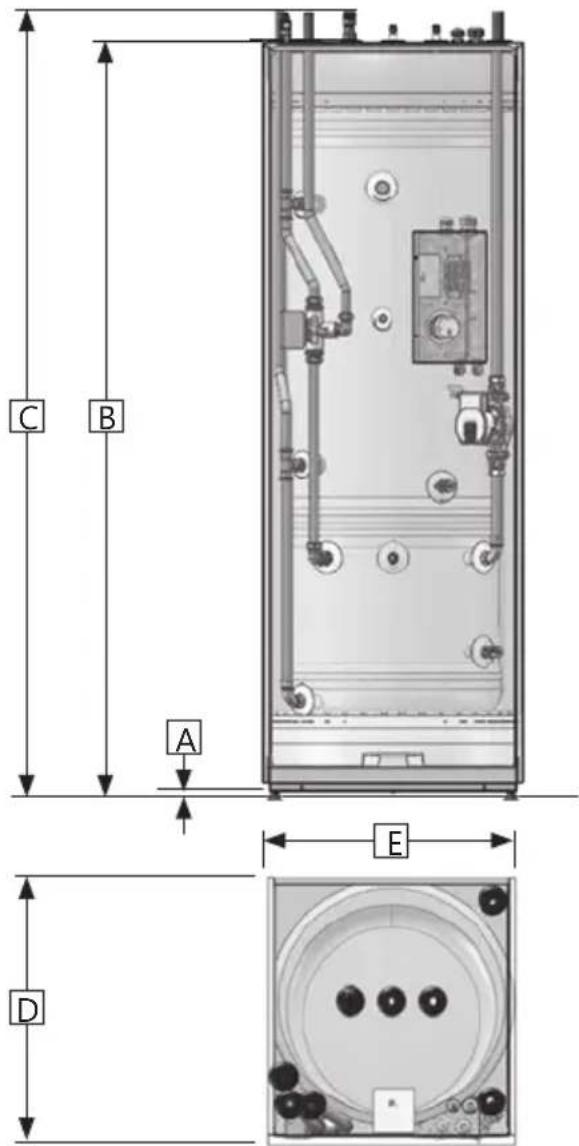
natural_image
Illustration of two human figures carrying boxes with diagonal lines, no text or symbols present3.4 Изисквания за монтаж, местоположение и позициониране
natural_image
3D diagram of a white refrigerator with labeled parts (1, 2, 3), showing front and side views without any text or symbols.4. ПОДДРЪЖКА И ИЗТОЧВАНЕ
natural_image
Technical diagram of a cylindrical industrial vessel with internal components and labeled section A (no text or symbols beyond label)⚠️ ПРЕДУПРЕЖДЕНИЕ
6. ГАРАНЦИОННИ УСЛОВИЯ
ГАРАНЦИЯ
1. Обхват
natural_image
Technical line drawing of a rectangular industrial or mechanical enclosure with internal components and no visible text or symbols.BEZPEČNOSTNÍ INFORMACE
NÁVOD K INSTALACI
NÁVOD K OBSLUZE
TECHNICKÉ ÚDAJE
OBSAH
natural_image
Illustration of a large industrial battery with warning symbol and warning label (no text or symbols on main body)
natural_image
Illustration of two workers carrying boxes with a diagonal line crossing, no text or symbols present4. ÚDRŽBA A VYPOUŠTĚNÍ
natural_image
Technical diagram of a cylindrical industrial vessel with internal components and piping (no text or labels)⚠️ VAROVÁNÍ
6. ZÁRUČNÍ PODMÍNKY
ZÁRUKA
1. Rozsah
natural_image
Technical line drawing of a rectangular industrial or mechanical enclosure with internal components and no visible text or symbols.INSTALLATIONSVEJLEDNING SIKKERHEDSINFORMATION BETJENINGSANVISNINGER TEKNISK DATABLAD (TDB)
INDHOLDSFORTEGNELSE
natural_image
Illustration of a large industrial battery with warning symbol and warning label (no text or symbols on main body)
3.3.2 Rørtislutninger og ventiler
4. VEDLIGEHOLDELSE OG T∅MNING
natural_image
Technical diagram of a cylindrical industrial vessel with internal components and piping (no text or symbols)⚠ ADVARSEL
Udskift anoden, hvis diameteren er mindre end 10 mm. Anoden beskytter beholderen mod aggressive kemiske stoffer i vandet.
6. GARANTIBETINGELSER
GARANTI
1. Omfang
natural_image
Technical line drawing of a rectangular industrial or mechanical enclosure with internal components and no visible text or symbols.natural_image
Illustration of a large industrial battery with warning symbol and warning label (no text or symbols on main body)
natural_image
Illustration of two human figures carrying boxes with diagonal lines, no text or symbols present3.5 Rohrinstallation
natural_image
Technical diagram of a cylindrical industrial vessel with internal components and piping (no text or symbols)
WARNUNG
6. GARANTIEBEDINGUNGEN
GARANTIE
1. Umfang
natural_image
Technical line drawing of a rectangular industrial or mechanical enclosure with internal components and no visible text or symbols.natural_image
Illustration of a rectangular battery with warning symbol and warning label (no text or symbols on main body)
natural_image
Illustration of three human figures carrying boxes with diagonal lines, no text or symbols present⚠️ ΠΡΟΣΟΧΗ
natural_image
Technical diagram of a cylindrical industrial vessel with internal components and labeled section A (no text or symbols beyond label)⚠️ ΠΡΟΕΙΔΟΠΟΙΗΣΗ
6. ΟΡΟΙ ΕΓΓΥΗΣΗΣ
ΕΓΓΥΗΣΗ
1. Πεδίο εφαρμογής
natural_image
Technical line drawing of a rectangular industrial or mechanical enclosure with internal components and no visible text or symbols.natural_image
Illustration of a rectangular battery with warning symbol and warning label (no text or symbols on main body)
natural_image
Illustration of two human figures carrying boxes with diagonal lines, no text or symbols presentnatural_image
Technical diagram of a cylindrical industrial vessel with internal components and piping (no text or symbols)
ADVERTENCIA
6. CONDICIONES DE LA GARANTÍA
GARANTÍA
1. Ámbito
natural_image
Technical line drawing of a rectangular industrial or mechanical enclosure with internal components and no visible text or symbols.OHUTUSTEAVE
PAIGALDUSJUHEND
KASUTUSJUHEND
TDS - TEHNILINE ANDMELEHT
SISUKORD
1. Ohutusjuhised 3.
natural_image
Illustration of a large rectangular device with a warning symbol and an exclamation mark, no text or labels present.
natural_image
Illustration of two human figures carrying boxes with diagonal lines, no text or symbols present4. HOOLDUS JA TÜHJENDAMINE
natural_image
Technical diagram of a cylindrical industrial vessel with internal components and labeled section A (no text or symbols beyond label)△! HOIATUS
6. GARANTIITINGIMUSED
GARANTII
1. Kehtivusala
natural_image
Technical line drawing of a rectangular industrial or mechanical enclosure with internal components and no visible text or symbols.TURVALLISUUSTIEDOT
ASENNUSOHJEET
KÄYTTÖOHJEET
TDS - TEKNINEN ESITE
SISÄLTÖ
natural_image
Illustration of a large industrial battery with warning symbol and warning label (no text or symbols on main body)
4. KUNNOSSAPITO JA TYHJENNYS
natural_image
Technical diagram of a cylindrical industrial device with internal components and labeled section A (no text or symbols beyond label)⚠️ VAROITUS
6. TAKUUEHDOT
TAKUU
1. Laajuus
natural_image
Technical line drawing of a rectangular industrial or mechanical enclosure with internal components and no visible text or symbols.CONSIGNES DE SÉCURITÉ MANUEL D'INSTALLATION INSTRUCTIONS DE FONCTIONNEMENT TDS - FICHE TECHNIQUE
SOMMAIRE
natural_image
Illustration of a rectangular battery unit with warning symbol and warning label (no text or symbols on main body)
natural_image
Illustration of two human figures carrying boxes with diagonal lines, no text or symbols present3.5.6 Instructions de raccordement
4. ENTRETIEN ET VIDANGE
natural_image
Technical diagram of a cylindrical industrial vessel with internal components and piping (no text or symbols)
AVERTISSEMENT
6. CONDITIONS DE GARANTIE
GARANTIE
1. Étendue
natural_image
Technical line drawing of a rectangular industrial or mechanical enclosure with internal components and no visible text or symbols.PRIRUČNIK ZA UGRADNJU S INFORMACIJAMA O SIGURNOSTI I RADNE UPUTE TPL - TEHNIČKI PODATKOVNI LIST
SADRŽAJ
1. Sigurnosne upute .... 3
1.1 Opći podaci.... 3
1.2 Sigurnosne upute za korisnike .... 4
1.3 Sigurnosne upute za montere 4
2. Opis proizvoda 5
2.1. Identifikacija proizvoda 5
2.2. Namjena 5
2.3 CE oznaka.... 5
2.4 Tehnički podaci.... 5
2.5. ErP podaci (TPL).... 5
3. Upute za ugradnju 6
3.1. Proizvodi obuhvaćeni ovim uputama ... 6
3.2. Sastavni dio isporuke 6
3.3. Mjere proizvoda 6
3.4. Zahtjevi koje mora zadovoljavati
mjesto za ugradnju 7
3.5. Ugradnja cijevi 8
3.6. Električna instalacija.... 10
4. Održavanje i pražnjenje.... 12
natural_image
Illustration of a rectangular battery with warning symbol and warning label (no text or symbols on main body)Simboli koji se upotrebljavaju u ovom priručniku:
| ⚠ UPOZORENJE | Može doći do ozbiljne ozljede ili smrtnog slučaja. |
| ⚠ OPREZ | Može uzrokovati manju ili umjerenu ozljedu ili štetu na imovini |
| ∅ | NIJE DOPUŠTENO |
| ! | DOPUŠTENO |

3.3.2 Spojevi cijevi i ventili
natural_image
Illustration of two human figures carrying boxes, one with a diagonal line crossing the other (no text or symbols)| ⚠ UPOZORENJE |
| Konstantni tlak prisutan u elektroničkoj kutiji. Prije obavljanja električnih radova strujno napa- janje mora se odspojiti i zaštititi od aktiviranja dok su radovi u tijeku. |
| Termostat se nikada ne smije rastavljati/otva- rati. To će ugroziti njegovu funkciju i dovesti do rizika od pregrijavanja. Jamstvo je ništavno. |
3.6.3 Upute za postavljanje
4. ODRŽAVANJE I PRAŽNJENJE
natural_image
Technical diagram of a cylindrical industrial vessel with internal components and labeled section A (no text or symbols beyond label)⚠ UPOZORENJE
6. JAMSTVENI UVJETI
JAMSTVO
1. Opseg
natural_image
Technical line drawing of a rectangular industrial or mechanical enclosure with internal components and no visible text or symbols.ÜZEMBIZTONSÁGI TÁJÉKOZTATÓ BESZERELÉSI ÚTMUTATÓ MÜKÖDTETÉSI ÚTMUTATÓ TDS - MÜSZAKI ADATLAP
TARTALOMJEGYZÉK
natural_image
Illustration of a large industrial battery with warning symbol and warning label (no text or symbols on main body)
natural_image
Illustration of two human figures carrying boxes with diagonal lines, no text or symbols presentnatural_image
Technical diagram of a cylindrical industrial vessel with internal components and piping (no text or labels)⚠ VIGYÁZAT
6. GARANCIÁLIS FELTÉTELEK
GARANCIA
1. Hatály
natural_image
Technical line drawing of a rectangular industrial or mechanical enclosure with internal components and no visible text or symbols.natural_image
Illustration of a rectangular battery with warning symbol and warning label (no text or symbols on main body)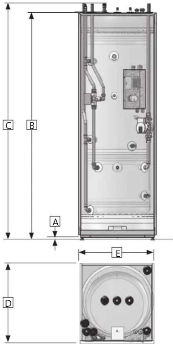
natural_image
Illustration of two human figures carrying boxes with diagonal lines, no text or symbols presentnatural_image
Technical diagram of a cylindrical industrial vessel with internal components and labeled section A (no text or symbols beyond label)AVVERTENZA
natural_image
Technical line drawing of a rectangular industrial or mechanical enclosure with internal components and no visible text or symbols.DROŠĪBAS INFORMĀCIJAS UZSTĀDĪŠANAS ROKASGRĀMATAS LIETOŠANAS INSTRUKCIJAS TDL - TEHNISKO DATU LAPA
SATURS
natural_image
Illustration of a large rectangular battery with warning symbol and warning label (no text or symbols on main body)2. PRODUKTA APRAKSTS

3.3.2. Caurułu savienojumi un vârsti
natural_image
Illustration of two human figures carrying boxes with diagonal lines, no text or symbols present4. UZTURĒŠANA UN IZTUKŠOŠANA
natural_image
Technical diagram of a cylindrical industrial vessel with internal components and piping (no text or symbols)
BRĪDINĀJUMS
6. GARANTIJAS NOSACIJUMI
GARANTIJA
1. Darbības joma
natural_image
Technical line drawing of a rectangular industrial or mechanical enclosure with internal components and no visible text or symbols.VEILIGHEIDSINFORMATIE INSTALLATIEHANDLEIDING GEBRUIKSAANWIJZING TDS-TECHNISCH FICHE
INHOUD
natural_image
Illustration of a rectangular battery with warning symbol and warning label (no text or symbols on main body)2. PRODUCTBESCHRIJVING
2.1 Productidentificatie

natural_image
Illustration of two human figures carrying boxes with diagonal lines, no text or symbols present4. ONDERHOUD EN AFVOER
natural_image
Technical diagram of a cylindrical industrial vessel with internal components and piping (no text or symbols)⚠ WAARSCHUWING
6. GARANTIEVOORWAARDEN
GARANTIE
1. Bereik
natural_image
Technical line drawing of a rectangular industrial or mechanical enclosure with internal components and no visible text or symbols.SIKKERHETSINFORMASJON
FDV INFORMASJON
MONTASJEANVISNING
TDS - TECHNICAL DATA SHEET
INNHOLDSFORTEGNELSE
1. Sikkerhetsinstruks 3
natural_image
Illustration of a rectangular battery with warning symbol and warning label (no text or symbols on main body)
natural_image
Illustration of two human figures carrying boxes, one with a diagonal line crossing the other (no text or symbols)4. VEDLIKEHOLD OG AVTAPNING
natural_image
Technical diagram of a cylindrical industrial vessel with internal components and piping (no text or symbols)ADVARSEL
6. GARANTIBETINGELSER
GARANTI
1. Omfang
natural_image
Technical line drawing of a rectangular industrial or mechanical enclosure with internal components and no visible text or symbols.INFORMACJE DOTYCZĄCE BEZPIECZEŃSTWA
INSTRUKCJA MONTAŻU
INSTRUKCJA OBSŁUGI
KARTA DANYCH TECHNICZNYCH (TDS)
SPIS TREŚCI
natural_image
Illustration of a large rectangular battery with warning symbol and warning label (no text or symbols on main body)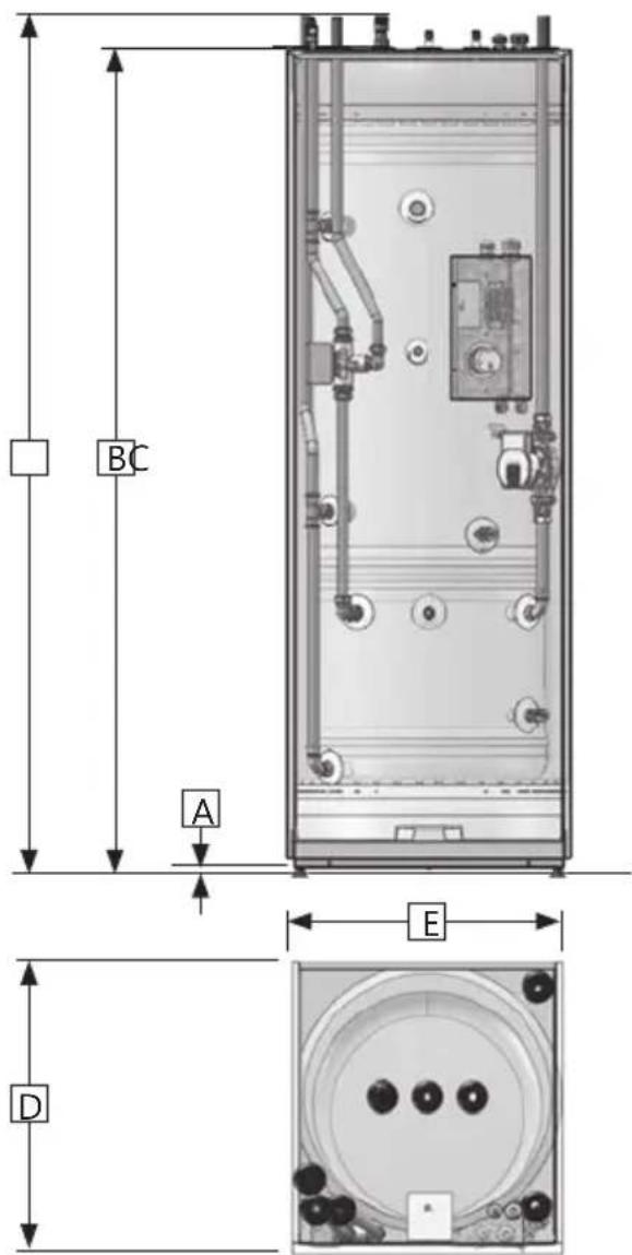
natural_image
Illustration of two human figures carrying boxes with diagonal lines, no text or symbols presentnatural_image
Diagram of a white refrigerator with labeled parts (1, 2, 3), showing internal structure and mounting points (no text or symbols beyond labels)4. KONSERWACJA I OPRÓŻNIANIE
natural_image
Technical diagram of a cylindrical industrial vessel with internal components and labeled section A (no text or symbols beyond label)
OSTRZEŻENIE
6. WARUNKI GWARANCJI
GWARANCJA
1. Zakres gwarancji
natural_image
Technical line drawing of a rectangular industrial or mechanical enclosure with internal components and no visible text or symbols.natural_image
Illustration of a rectangular battery with warning symbol and warning label (no text or symbols on main body)Símbolos utilizados neste manual:

natural_image
Illustration of two human figures carrying boxes with diagonal lines, no text or symbols presentnatural_image
Technical diagram of a cylindrical industrial vessel with internal components and piping (no text or labels)AVISO
6. CONDIÇÕES DA GARANTIA
GARANTIA
1. Âmbito
natural_image
Technical line drawing of a rectangular industrial or mechanical enclosure with internal components and no visible text or symbols.INFORMATII PRIVIND SIGURANTA
MANUAL DE INSTALARE
INSTRUCTIUNI DE UTILIZARE
FDT - FIŞÃ DE DATE TEHNICE
CONTINUT
natural_image
Illustration of a large industrial container with warning symbol and warning label (no text or symbols on main body)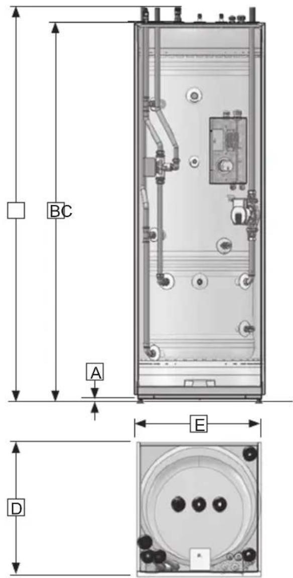
natural_image
Two silhouettes of people carrying boxes with diagonal lines, no text or symbols present4. ÎNTRETINEREA ŞI DRENAREA
natural_image
Technical diagram of a cylindrical industrial vessel with internal components and piping (no text or symbols)
AVERTIZARE
6. CONDIȚIILE GARANȚIEI
GARANTIE
1. Scop
natural_image
Technical line drawing of a rectangular industrial or mechanical enclosure with internal components and no visible text or symbols.SÄKERHETSINFORMATION
SÄKERHETSMANUAL
BRUKSANVISNING
TDS – TEKNISKT DATABLAD
INNEHÅLL
natural_image
Illustration of a large rectangular battery with warning symbol and warning label (no text or symbols on main body)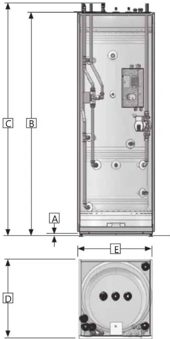
3.5.3 Rörinstallation, procedur
4. UNDERHÅLL OCH TÖMNING
natural_image
Technical diagram of a cylindrical industrial vessel with internal components and piping (no text or symbols)⚠️ WARNING
6. GARANTIVILLKOR
GARANTI
1. Omfattning
natural_image
Technical line drawing of a rectangular industrial or mechanical enclosure with internal components and no visible text or symbols.BEZPEČNOSTNÉ INFORMÁCIE
NÁVOD NA INŠTALÁCIU
NÁVOD NA OBSLUHU
TDS - KARTA TECHNICKÝCH ÚDAJOV
OBSAH
natural_image
Illustration of a large industrial battery with warning symbol and warning label (no text or symbols on main body)3. POKYNY NA INŠTALÁCIU

3.3.2 Pr pojky potrubia a ventily
Ref. Dim. Popis a
a ø22 N vrat radi torov ho okruhu b
b ø22 Studen itkov voda dnu
3.5.5 Schéma pripojenia potrubia
4.ÚDRŽBA A VYPÚŠŤANIE
natural_image
Technical diagram of a cylindrical industrial or gas storage unit with internal components and piping (no text or symbols visible)⚠️ VAROVANIE
6. ZÁRUČNÉ PODMIENKY
ZÁRUKA
1. Rozsah
natural_image
Technical line drawing of a rectangular industrial or mechanical enclosure with internal components and no visible text or symbols.GÜVENLİK BİLGİLERİ
KURULUM EL KİTABI
İŞLETİM TALİMATLARI
TDS - TEKNİK VERİ SAYFASI
iÇERİK
natural_image
Illustration of a rectangular battery with warning symbol and warning label (no text or symbols on main body)pH seviyesi > 6,0 / < 9,5
pH seviyesi > 6,0 / < 9,5


natural_image
Illustration of two human figures carrying boxes with diagonal lines, no text or symbols present4. BAKIM VE TAHLİYE
natural_image
Technical diagram of a cylindrical industrial vessel with internal components and labeled section A (no text or symbols beyond label)UYARI
6. GARANTI KOŞULLARI
GARANTI
1. Kapsam

- CONTENTS
- Safety instructions .... 3
- Product description 5
- Installation instructions 6
- Maintenance and draining.... 12
- Spare parts.... 13
- Warranty conditions.... 14
- Recycling and handover 15
- Dear customer
- SAFETY INSTRUCTIONS
- General information
- Safety instructions for users
- Safety instructions for installers
- PRODUCT DESCRIPTION
- Product identification
- Intended use
- CE marking
- CE
- INSTALLATION INSTRUCTIONS
- Products covered by these instructions
- Included in delivery
- Product dimensions
- Important notice before installation
- Pipe connections and valves
- Transport and unpacking
- Requirements for installation, location and positioning
- Pipe installation
- Heating and domestic hot water
- Pipe installation procedure
- Removing the front cover
- Pipe connection layout
- Fitting instructions
- Installation recommendation
- Electrical installation
- Backup immersion heater thermostat
- 4.MAINTENANCE AND DRAINING
- Checking the manometer
- Checking the temperature & pressure relief valve
- ⚠ WARNING
- Checking the protective anode (if installed)
- Draining the product
- SPARE PARTS
- Spare parts list
- WARRANTY CONDITIONS
- WARRANTY
- Scope
- Coverage
- Conditions
- Limitations
- RECYCLING
- Information for users on collection and disposal of old equipment:
- Disposal
- PAW-TD23B6E5
- Изисквания за монтаж, местоположение и позициониране
- ПОДДРЪЖКА И ИЗТОЧВАНЕ
- ⚠️ ПРЕДУПРЕЖДЕНИЕ
- ГАРАНЦИОННИ УСЛОВИЯ
- ГАРАНЦИЯ
- Обхват
- OBSAH
- ÚDRŽBA A VYPOUŠTĚNÍ
- ⚠️ VAROVÁNÍ
- ZÁRUČNÍ PODMÍNKY
- ZÁRUKA
- Rozsah
- INDHOLDSFORTEGNELSE
- Rørtislutninger og ventiler
- VEDLIGEHOLDELSE OG T∅MNING
- ⚠ ADVARSEL
- GARANTIBETINGELSER
- GARANTI
- Omfang
- Rohrinstallation
- WARNUNG
- GARANTIEBEDINGUNGEN
- GARANTIE
- Umfang
- ⚠️ ΠΡΟΣΟΧΗ
- ⚠️ ΠΡΟΕΙΔΟΠΟΙΗΣΗ
- ΟΡΟΙ ΕΓΓΥΗΣΗΣ
- ΕΓΓΥΗΣΗ
- Πεδίο εφαρμογής
- ADVERTENCIA
- CONDICIONES DE LA GARANTÍA
- GARANTÍA
- Ámbito
- SISUKORD
- Ohutusjuhised 3.
- HOOLDUS JA TÜHJENDAMINE
- △! HOIATUS
- GARANTIITINGIMUSED
- GARANTII
- Kehtivusala
- SISÄLTÖ
- KUNNOSSAPITO JA TYHJENNYS
- ⚠️ VAROITUS
- TAKUUEHDOT
- TAKUU
- Laajuus
- SOMMAIRE
- Instructions de raccordement
- ENTRETIEN ET VIDANGE
- AVERTISSEMENT
- CONDITIONS DE GARANTIE
- Étendue
- SADRŽAJ
- Sigurnosne upute .... 3
- Opis proizvoda 5
- Upute za ugradnju 6
- Održavanje i pražnjenje.... 12
- Spojevi cijevi i ventili
- Upute za postavljanje
- ODRŽAVANJE I PRAŽNJENJE
- ⚠ UPOZORENJE
- JAMSTVENI UVJETI
- JAMSTVO
- Opseg
- TARTALOMJEGYZÉK
- ⚠ VIGYÁZAT
- GARANCIÁLIS FELTÉTELEK
- GARANCIA
- Hatály
- AVVERTENZA
- SATURS
- PRODUKTA APRAKSTS
- Caurułu savienojumi un vârsti
- UZTURĒŠANA UN IZTUKŠOŠANA
- BRĪDINĀJUMS
- GARANTIJAS NOSACIJUMI
- GARANTIJA
- Darbības joma
- INHOUD
- PRODUCTBESCHRIJVING
- Productidentificatie
- ONDERHOUD EN AFVOER
- ⚠ WAARSCHUWING
- GARANTIEVOORWAARDEN
- Bereik
- INNHOLDSFORTEGNELSE
- Sikkerhetsinstruks 3
- VEDLIKEHOLD OG AVTAPNING
- ADVARSEL
- SPIS TREŚCI
- KONSERWACJA I OPRÓŻNIANIE
- OSTRZEŻENIE
- WARUNKI GWARANCJI
- GWARANCJA
- Zakres gwarancji
- AVISO
- CONDIÇÕES DA GARANTIA
- GARANTIA
- Âmbito
- CONTINUT
- ÎNTRETINEREA ŞI DRENAREA
- AVERTIZARE
- CONDIȚIILE GARANȚIEI
- Scop
- INNEHÅLL
- Rörinstallation, procedur
- UNDERHÅLL OCH TÖMNING
- ⚠️ WARNING
- GARANTIVILLKOR
- Omfattning
- POKYNY NA INŠTALÁCIU
- Pr pojky potrubia a ventily
- Schéma pripojenia potrubia
- 4.ÚDRŽBA A VYPÚŠŤANIE
- ⚠️ VAROVANIE
- ZÁRUČNÉ PODMIENKY
- iÇERİK
- BAKIM VE TAHLİYE
- UYARI
- GARANTI KOŞULLARI
- Kapsam
Brand : PANASONIC
Model : Aquarea PAW-TD23B6E5
Category : Water heater