
DH-3MS1 - Water heater PANASONIC - Free user manual and instructions
Find the device manual for free DH-3MS1 PANASONIC in PDF.


| Product Type | Electric Instantaneous Water Heater |
| Model | DH-3MS1 |
| Brand | Panasonic |
| Installation | Wall-mounted |
| Dimensions (H x W x D) | 320 mm x 180 mm x 110 mm |
| Weight | 2.5 kg |
| Power Supply | 220-240 V ~ 50/60 Hz |
| Rated Power | 3.0 kW |
| Water Connection | G 1/2 inch |
| Max Water Temperature | 60 °C |
| Min Operating Water Pressure | 0.1 MPa |
| Max Operating Water Pressure | 0.6 MPa |
| Flow Rate (at 25°C rise) | 3.0 L/min |
| Heating Element | Copper immersion heater |
| Control Type | Manual on/off with temperature selection |
| Safety Features | Thermal cut-off, pressure relief valve, IPX4 splash-proof |
| Energy Efficiency Class | B (for water heating) |
| Noise Level | < 40 dB(A) |
| Maintenance | Descaling every 6 months; clean inlet filter |
| Spare Parts Availability | Heating element, thermostat, pressure switch, inlet valve |
| Warranty | 2 years (subject to terms) |
| Certifications | CE, RoHS |
Frequently Asked Questions - DH-3MS1 PANASONIC
User questions about DH-3MS1 PANASONIC
0 question about this device. Answer the ones you know or ask your own.
Ask a new question about this device
Download the instructions for your Water heater in PDF format for free! Find your manual DH-3MS1 - PANASONIC and take your electronic device back in hand. On this page are published all the documents necessary for the use of your device. DH-3MS1 by PANASONIC.
USER MANUAL DH-3MS1 PANASONIC
Please retain the warranty card printed on the last page of this booklet and ensure to register the warranty online at www.panasonic.com.my 重要通知
B.MALAYSIA
Panduan Penggunaan
Operating Instructions
(Installation Instructions included) 12 - 21
中文
使用说明书
(包括安装说明) 22-31
Thank you for purchasing the Panasonic Electric Home Shower. This appliance is intended for household use only. For optimum performance and safety, please carefully read this Operating Instructions and keep this documentation in a safe place for future reference.
natural_image
Pure mechanical diagram showing a valve or fitting with a handle and internal components, no text or symbols present.4. PANDUAN KEROSAKAN
Tombol Kawalan Kuasa / Tombol Kawalan Suhu
Nota
natural_image
Three technical line drawings of mechanical components or assemblies, showing internal and external views (no text or symbols)Bahagian 1 Bahagian 2

PERHATIAN

4. Pendawaian elektrik

AMARAN

1. SAFETY INSTRUCTIONS
SAFETY INSTRUCTIONS
To be followed absolutely
Before operating, please read the following "Safety Instructions" carefully.
To prevent personal injury, injury to others and property damage, the following instructions must be followed.
Incorrect operation caused by failure to follow instructions will cause harm or damage, the seriousness of which is classified as follow:

WARNING
This sign warns of death or serious injury.

CAUTION
This sign warns of injury to users or damage to property.
The instructions to be followed are classified by the following symbols:

This symbol (with a white background) denotes an action that is PROHIBITED.


This symbol (with a black background) denote action that is COMPULSORY.

WARNING

Stop using the Unit when any abnormality/failure occurs and turn "OFF" the Miniature Circuit Breaker (MCB). (Risk of smoke/fire/electric shock/scalding)
The ELB Reset Lever cannot be reset. Please refer to item no. 3. TEST OPERATION at page 21.
- Burnt odor, or smoke is detected during operation.
abnormally. The Front Plate/Back Plate is deformed or abnormally hot.
• The outlet water temperature become extremely hot and cannot be controlled using the Power Control Knob / Temperature Control Knob.
Contact your authorized dealer immediately for maintenance/repair.

The Unit must be earthed.
Improper grounding could cause electric shock.

Switch off the Miniature Circuit Breaker (MCB) before any service.

In time of lightning/ thunder, switch "OFF" the Miniature Circuit Breaker (MCB) in advance to protect the shower Unit against possible damage.

Inspect on the built-in ELB (once a month) to avoid a hazard to users such as damage to property, serious injury or death. Please refer to item no. 3. TEST OPERATION at page 21.

Each time shower water is turned 'ON', check the water temperature by hand before showering.

When the shower is used by someone such as child, old person, sick person and physically handicapped person, the person responsible for their safety is kindly requested to pay attention and check the shower temperature by using hand from time to time.

Pay attention to shower temperature when reducing the volume of water. The shower temperature will become very hot if the water flow rate is too low.

This appliance is not intended for use by persons (including children) with reduced physical, sensory or mental capabilities, or lack of experience and knowledge, unless they have been given supervision or instruction concerning use of the appliance by a person responsible for their safety. Children should be supervised to ensure that they do not play with the appliance.

- If the ELB Reset Lever cannot be reset even if you push it up or if it soon slides down during operation, please do not use the Unit and contact the authorized dealer immediately. Never fix the ELB Reset Lever forcibly with tape, etc.

- Do not insert finger or other objects into the electric home shower Unit to avoiding physical and electric shock hazards.

- Do not replace the Shower Head, Shower Hose or any other parts of the Unit with spare parts other than genuine parts.
Parts for other models will not fit to this model and may cause hazardous condition to user.
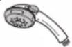

Shower Head Shower Hose

- Do not spray water to the Unit, nor put wet towels on it to avoid from coming into contact with any live parts etc., in order to prevent smoke emission, ignition, fire and electric shock hazards.
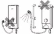

- Metallic/chrome hose and conductive valve shall not be used.

CAUTION

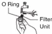
Please make sure the O Ring is not removed and shall be free from foreign particle to avoid water leaking.

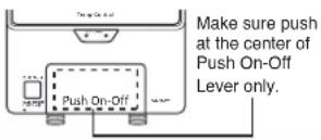
Press Push On-Off Lever before and after each shower.
Press the Push On-Off Lever only. Do not pull.

Never use benzene, thinner, bleaching agent, etc. for cleaning purpose to avoid smoke emission, ignition, fire and electric shock hazards.


Avoid using dirty water as it may affect heater performance and other components.

- Do not block the Shower Head with hand, towel or bend the hose. The water flow rate will drop and water temperature may become very hot.
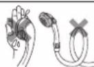

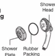
• Take care not to damage the holes of the Shower Plate during the cleaning. The Rubber Packing shall be set on the Shower Head before fixing back the Shower Plate to Shower Head. Do not remove part other than Shower Plate and Rubber Packing.

- In order to avoid a hazard due to inadvertent resetting of the thermal cut-out, this appliance must not be supplied through an external switching device, such as a timer, or connected to a circuit that is regularly switched on and off by the utility.
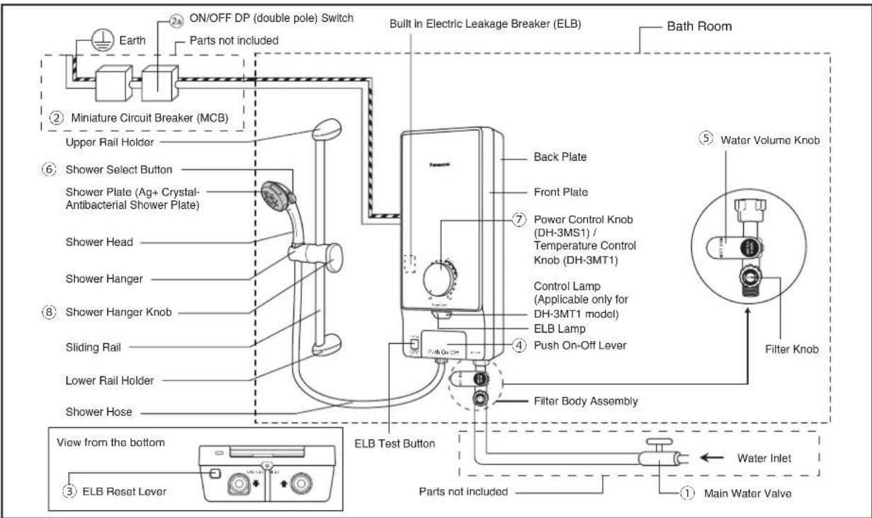
- PARTS IDENTIFICATION
- ACCESSORIES
| Description: | Items: | ||
 Shower Head Packing Shower Head Packing |  Shower Head (1 set) Shower Head (1 set) | ||
 Shower Hanger Packing Shower Hanger Packing |  Shower Hose (1 set) Shower Hose (1 set) | 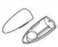 X 2Rail Holder (2 set) X 2Rail Holder (2 set) | 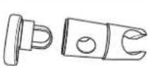 Shower Hanger Ass'y (1 set) Shower Hanger Ass'y (1 set) |
 Installation Packing Installation Packing |  6 X 2Wall Plug (6 pcs) Rubber Packing (2 pcs) Screws (6 pcs) 6 X 2Wall Plug (6 pcs) Rubber Packing (2 pcs) Screws (6 pcs) |  |  |
 Filter Body Packing Filter Body Packing | 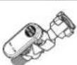 Filter Body Assembly (1 set) Rubber Packing (1 pc) Filter Body Assembly Caution Sheet (1 pc) Filter Body Assembly (1 set) Rubber Packing (1 pc) Filter Body Assembly Caution Sheet (1 pc) |  |  |
 Sliding Rail Sliding Rail |  Sliding Rail (1 pc) Sliding Rail (1 pc) | ||
 Installation Packing Installation Packing |  X 8 X 2Wall Plug (8 pcs) Rubber Packing (2 pcs) Screws (8 pcs) X 8 X 2Wall Plug (8 pcs) Rubber Packing (2 pcs) Screws (8 pcs) |  |  |
HOW TO USE ELECTRIC HOME SHOWER
1. HOW TO USE
- Turn "On" the Main Water Valve.
- Switch "On" the Miniature Circuit Breaker (MCB) and ON/OFF DP (double pole) Switch.
- Push the ELB Reset Lever if it is down.
- Turn Water Volume Knob to clockwise.
- Turning it clockwise increases the volume of water thus decrease the water temperature.
- Turning it anticlockwise decreases the volume of water thus increase the water temperature.
-
Press the Push On-Off Lever, water will start flowing from the Shower Head and the ELB light will turn red.
-
To stop the water flow, press the Push On-Off Lever again (the position of the Push On-Off Lever remains the same).
- This button controls both water and electricity supply to the set.
- Adjust to the desired shower condition by operating the Water Volume Knob and the Power Control Knob / Temperature Control Knob.
Then the operation can be made easily by pushing the Push On-Off Lever only.

CAUTION

Press Push On-Off Lever before and after each shower.
Press the Push On-Off Lever only. Do not pull.
6. Temperature setting
DH-3MS1
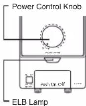
(a) The shower temperature can be gradually controlled by setting the Power Control Knob to the desired position.
(b) If you turn the Power Control Knob clockwise the shower temperature will go up, reaching the highest temperature at "High". The temperature can be gradually controlled.
(c) If the Power Control Knob is at "Off" position, the water temperature will remain at inlet temperature.
(d) In case of continuous usage at high temperature setting, water temperature will increase and it may cause the control device in the set to activate temporarily resulting water temperature to drop.
DH-3MT1
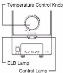
(a) The shower temperature can be gradually controlled by setting the Temperature Control Knob to the desired position.
(b) If the Temperature Control Knob is turned clockwise to 'Recommended Temp', you can get comfortable water temperature.
(c) If the Temperature Control Knob is at "Off" position, the water temperature will remain at inlet water temperature.
(d) Control Lamp (orange) will light up when water temperature is stable at the desired position.
(e) Control Lamp will turn off when water flow is too much, and it is beyond the controllable range.
(f) Reduce the water flow by turning the Water Volume Knob anticlockwise until Control Lamp is "On".
(g) In case of continuous usage at high temperature setting, water temperature will increase and it may cause the control device to activate temporarily resulting water temperature to drop.
-
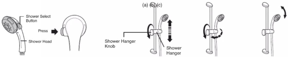
Select the preferred shower with the Shower Select Button. Please press the button fully.
-
Shower head can be set to various position.
(a) Loosen Shower Hanger Knob and adjust higher or lower.
Tighten Shower Hanger Knob.
(b) Loosen Shower Hanger Knob and Shower Hanger can be adjusted to the left or right. Tighten Shower Hanger Knob.
(c) The angle of Shower Head can be adjusted by moving the Shower Head upper or lower.
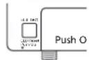
ELB: ON condition
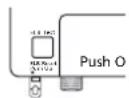
ELB: OFF condition
DH-3MS1
DH-3MT1
2. WATER FLOW RATE ADJUSTMENT
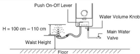
(1) How to adjust to maximum water flow rate.
Step 1: Push the Push On-Off Lever and select Wide Shower type on the Shower Head using the Shower Select Button (refer Figure 1).
Step 2: Turn "Off" the Main Water Valve.
Step 3: Turn the Shower Head upward at waist height.
Step 4: Turn the Water Volume Knob to maximum volume position (refer Figure 2).
Step 5: Gradually "On" the Main Water Valve and adjust the splashing height (H) of the shower.
It is recommended to adjust the water splashing height (H) at 100 cm \~ 110cm (approximately 3L/min).
(If splashing height (H) is too high, hot water temperature will drop because of an excessive flow rate).
Note: 1. Pay attention to shower temperature when reducing the volume of water.
The shower temperature will become very hot if the water flow rate is too low.
- Water Volume Knob is at maximum position at this stage (refer Step 4).
Please adjust it to suitable flow rate using the Water Volume Knob by turning it anticlockwise.

Spot Shower

Normal Shower

Wide Shower
Shower Select Button

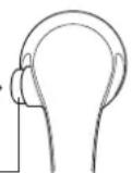
Figure 1 Figure 2
Water Volume Knob
3. MAINTENANCE

WARNING

Switch "OFF" the Miniature Circuit Breaker (MCB) before service.
(1) Main Body cleaning.
Be sure to switch "OFF" the Miniature Circuit Breaker beforehand.
1) Clean it with moist cloth.
2) Never use benzene, thinner, detergent, bleach, etc.
3) Do not spray water to the unit, not put wet towels on it.
4) Make sure to use suitable cloth to clean the Front Plate surface to avoid scratch.
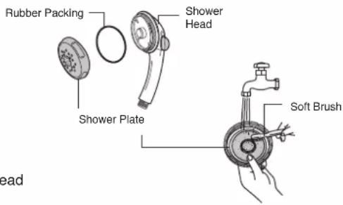
(2) Shower Head cleaning.
1) Turn the Shower Plate anticlockwise and remove it from the Shower Head with hand.
2) Clean the Shower Plate's holes by using a soft brush from time to time. (Recommended once a week).

CAUTION

Take care do not damage the holes of the Shower Plate during the cleaning. The Rubber Packing shall be set on the Shower Head before fixing back the Shower Plate to Shower Head. Do not remove other parts other than Shower Plate and Rubber Packing.
(3) Filter Unit Cleaning (Filter Unit is fixed to Filter Knob)
Clean the Filter of the Filter Unit with water once a week.
Clean the Filter Unit when hot water is not drawn normally.
Dismantle, cleaning and assemble of Filter Unit
① Close the Main Water Valve.
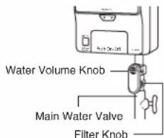
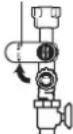
② Turn Water Volume Knob clockwise if it is blocking the Filter Knob. Turn the Filter Knob anticlockwise and pull it out.
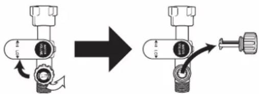
③ Clean the Filter Unit.
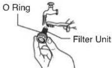
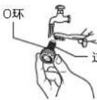
Please make sure the O Ring is not removed and shall be free from foreign particle to avoid water leaking.
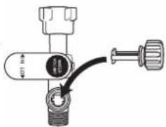
④ Insert the Filter Unit and tighten it properly (clockwise).
⑤ Turn the Water Volume Knob to its original position base on Water Flow Rate Adjustment at page 16.
natural_image
Mechanical valve assembly diagram showing a knob and adjustment knob (no text or labels)4. TROUBLESHOOTING
(1) Check the following points before asking for repair.
| Symptom Points to | be checked |
| Water is not drawn normally. | 1. Check the Filter Unit. Clean the Filter if it is clogged by stain and dirt (refer Filter Unit Cleaning as above).2. Check the Shower Head and Shower Plate. Clean the Shower Head and Shower Plate if it is clogged by dirt (refer Shower Head Cleaning at page 16). |
| No hot water comes out from the outlet(no electric supply to the unit) | 1. Make sure the Push On-Off Lever is at “On” position.2. Make sure the ELB Reset Lever is not slide down.Push up the ELB Reset Lever to reset the ELB (see TEST OPERATION at page 21).3. Make sure to switch on the ON/OFF DP (double pole) Switch.4. Make sure to switch on the Miniature Circuit Breaker (MCB). |
| No water flows out from the Shower Head at all. | 1. Check the Main Water Valve. Turn “On” the Main Water Valve if it is closed (refer HOW TO USE at page 15).2. Check the ELB Lamp (Red) indication.Red lamp light “Off”. Check the Push On-Off Lever, if the red lamp still light “Off”.please do not use the unit and contact the authorized dealer immediately. |
| Water not hot enough. | 1. Check the WATER FLOW RATE ADJUSTMENT as in page 16. |
(2) If abnormalities as mentioned below are found during use, please do not use the Unit and contact your authorized dealer immediately.
1) Water leakage.
2) No water flow.
3) Water temperature cannot be controlled.
4) ELB lamp does not light up.
(3) Special skill is required for repairing. Never try to repair the Unit by yourself.
5. SPECIFICATION
| Model | DH-3MS1 | DH-3MT1 |
| Voltage | 240 V a.c. 50 Hz | |
| Power Consumption | 3600 W | |
| Electric Power Control | Inlet Water Temp. (OFF), 1000 W ~ 3600 W | |
| Min. Water Pressure | 9.8 kPa / 0.1 kgf/cm2 / 1.42 psi | |
| Max. Water Pressure | 380 kPa / 3.87 kgf/cm2 / 55 psi | |
| Dimension | 420(H) mm x 185(W) mm x 85(D) mm | |
| Weight | 1.6 kg | 1.7 kg |
| Outlet System | Single Point System (Open Outlet) | |
HOW TO INSTALL ELECTRIC HOME SHOWER
WARNING

- Proper size of Flexible Cord and electric wiring must be installed to avoid smoke emission and fire hazards.
- During installation process make sure electric and water supply is turn "OFF".
• The home shower must be permanently connected to the electric supply through the ON/OFF DP (double pole) Switch having a contact separation of at least 3 mm in all poles incorporated in the fixed wiring. This switch must be clearly identifiable but out of reach of a person using a fixed bath or shower.

The Unit must be earthed.
Improper grounding could cause electric shock.

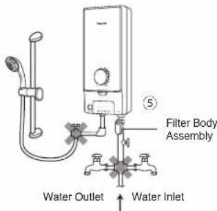
- Never install Filter Body Assembly at the outlet, inlet water cannot be filtered and allows foreign particles to enter the Unit. It will cause Heater Unit and Shower Head to clog up.
- Do not install, remove and reinstall the Unit by yourself.
Improper installation will cause leakage, electric shock or fire. Installation and wiring must be done by competent personnel. - Do not share the inlet and outlet pipe of the Home Shower Unit with other outlets.
The pressure may drop due to water being drawn off at other point. The shower temperature may become very hot.
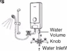
Outlet
CAUTION

- Flexible Cord must enter the Unit thru designated point only (do not make additional holes).
1. BEFORE INSTALLATION
(1) Make sure water flow pressure.
Min. water pressure 9.8 kPa / 0.1 kgf/cm² / 1.42 psi
Max. water pressure 380 kPa / 3.87 kgf/cm² / 55 psi
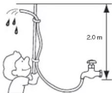
• How to measure the water pressure as illustrated. Water should flow out of the
Hose 2.0 m above the Main Water Valve.
Note: When removing the Unit from package, some water may be found inside.
This is normal as the Unit is tested during the manufacturing process.
2. HOW TO INSTALL

WARNING

During installation process make sure electric and water supply is turn "OFF".
-
Where to install the Unit.
-
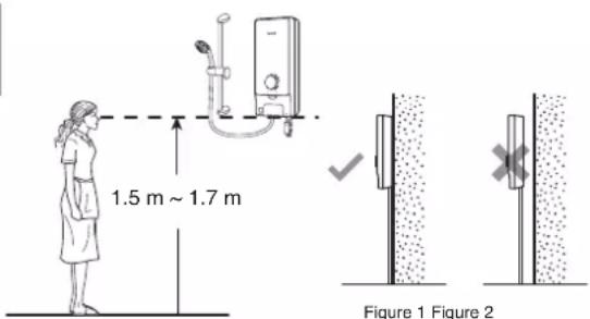
Be sure to install the Unit on the wall as illustrated in Figure 1 (vertical condition only).
- Do not install the Unit away from wall surface as shown in Figure 2.
-
The Unit must be installed at 1.5 m \~ 1.7 m above the floor.
-
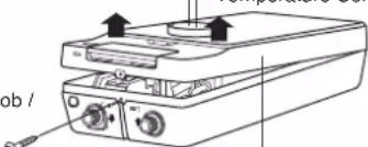
How to remove the Front Plate
① Make sure the Power Control Knob / Temperature Control Knob is at "Off" condition.
② Remove the screw at the bottom of the Unit.
③ Remove the Front Plate by lifting up the bottom side and then unhook the top side.
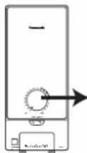

Power Control Knob / Temperature Control Knob
Note
Power Control Knob / Temperature Control Knob attached to Front Plate.
Lift up
Power Control Knob /
Temperature Control Knob
Screw
Front Plate
3. How to fix Electric Home Shower.
①
① The distance of the Unit should be more than 250 mm at right and left of the wall.
② Make 4 holes at the wall by means of a drill (refer Figure 1).
③ Drive a Wall Plug into the hole.
135 mm
② 25 mm
Wall Wall
Screw
383 mm
11.5 mm
11.5 mm
∅6 mm
③
Wall Plug
250 mm minimum
126 mm
171.7 mm
15 mm
Figure 1
④ Lead the Flexible Cord to the set thru Portion 1 or 2 as shown below for electric wiring process.
Portion 1
④
Portion 1 Portion 2
Portion 2
⑤ · Mount the Unit on the wall with 4 screws.
- Drive each Screw into the two upper Wall Plugs through the screw holes on the Back Plate.
• After tighten up the two upper Screws, tighten up the remaining two Screws.
⑤
Back Plate
Wall
Screw
Wall Plug
CAUTION
Flexible Cord must enter the Unit thru designated point only (do not make additional holes).
⑥ Please ensure the set fixed tightly on wall by shaking it left and right.
Note: The Back Plate must be mounted with 4 Screws.
⑥
Back Plate
Wall
Wall Plug
4. Electric wiring
WARNING
Proper size of Flexible Cord and electric wiring must be installed to avoid smoke emission and fire hazards.
WARNING
The home shower must be permanently connected to the electric supply through the ON/OFF DP (double pole) Switch having a contact separation of at least 3 mm in all poles incorporated in the fixed wiring. This switch must be clearly identifiable but out of reach of a person using a fixed bath or shower.
① Lead the Flexible Cord connected to ELB terminal inside the Unit: 2.5 mm ^4 , 3 core Flexible Cord.
Earth
Flexible Cord 2.5 mm², 3 core
② Unscrew the Cord Holder and fix the Flexible Cord. Strip the lead wire (coating). Fasten the live wire (L) and neutral wire (N) to the ELB (L,N) and earth wire to the Ground Point with 1 N·m (10 kgf.cm) torque. Fix back the Cord Holder to its position to clamp the Flexible Cord.
ON/OFF DP
(double pole) Switch
Miniature Circuit
Breaker (MCB)
Bath Room
1 N·m
L N
Ground
Point
L N
L N
ELB Terminal
Cord Holder
5 mm
13 mm 85 mm
L
N
13 mm
110 mm
Flexible
Cord
Main Power Board
③ Connect wires in correct polarity (L,N).
- Connect the wires in wrong polarity (L,N) causes an abnormal condition which may lead to electric leaking, burning, etc.
- Before wiring, please check polarity (L,N) with voltage range of a tester or voltmeter by connecting one terminal of the meter to earth while the other to one of the Power Supply terminals.
- When the needle of the meter deflects greatly, the polarity of the Power Supply terminal is 'L'.
Earth
Tester
Power-Supply
Terminals
Earth Rod

WARNING

The Unit must be earthed.
Improper grounding could cause electric shock.
• The Unit must be earthed.
- Earth Rod fixing procedure. Select suitable place to bury the optional Earth Rod (DQ-6H) for at least 70 cm below ground surface.
- Ensure that the ground resistance is less than 100 Ω. If it is not, drive the Rod deeper into ground surface or use 2 or 3 Rods.

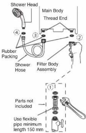
5. Piping installation procedure
① Place Rubber Packing between Filter Body Assembly and Flexible Pipe. Do not use Piping Tape. Tighten it by Spanner firmly.
② Place Rubber Packing between Filter Body Assembly and Main Body. Do not use Piping Tape. Tighten it by hand firmly.
③ Place Rubber Packing between Shower Hose and Main Body.
Do not use Piping Tape. Tighten it by hand firmly.
④ Place Rubber Packing between Shower Hose and Shower Head. Do not use Piping Tape. Tighten it by hand firmly.
⑤ The Filter Body Assembly should be placed in the front direction of the Unit.
| WARNING | Do not share the inlet or outlet pipe of Home Shower Unit with other outlets.The pressure may drop due to water being drawn off at other point. The shower water temperature may become very hot. | |
| CAUTION | Avoid using dirty water as it may affect heater performance and other components. | |
| Make sure no water leaks from pipe connection.NOTE: | ||
| NOTE: | When glue is used for external piping connection, must wait for the glue to dry before proceed to test run with water. | |
6. How to fix the Front Plate
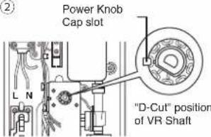
① Make sure the Power Control Knob / Temperature Control Knob on Front Plate and it is at "Off" position.
② Make sure the Power Knob Cap slot and the D-Cut position of the VR Shaft are located as shown (Off condition).
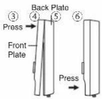
③ Close the Front Plate of the Unit according to the sequence as illustrated.
④ Push in the Power Control Knob / Temperature Control Knob until it is fully inserted
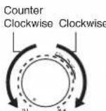
⑤ Please ensure to rotate the Power Control Knob / Temperature Control Knob clockwise until "High" and counter clockwise until "Off" to ensure the knob is fully inserted to the Power Knob Cap slot inside.
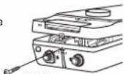
⑥ Fix the Screw at the bottom of the Unit.
①

Power Control Knob / Temperature Control Knob
②
Note:
- Do not push the ELB Test Button during fixing the Front Plate.
- Do not apply extreme force to insert the Power Control Knob / Temperature Control Knob during fixing the Front Plate because it will damage the switch inside the Unit.
7. Shower Hanger installation.
① Install the Rail Holder so that the Shower Head height not higher than the unit top.
Make sure the wall level must be same to the Rail Holder fixing position. If the wall is not at the same level, please use spacer (not included) to fix the accessory.
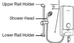
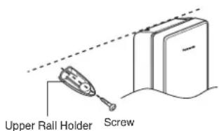
② Install the Upper Rail Holder on the wall but not higher than the unit top. Tighten the Upper Rail Holder with 1 screw.
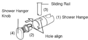
③ Prepare the Shower Hanger and Sliding Rail, remove the Shower Hanger Knob by turning it (anticlockwise) then install the parts following the number (1), (2), (3) and (4). Note: Make sure hole of Shower Hanger (1) is align with hole of Shower Hanger (2) and slot the Sliding Rail.
④ Tighten the Shower Hanger with Shower Hanger Knob.
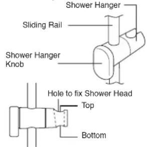
* Shower Hanger will drop off easily once the knob is loosen.
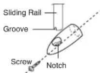
⑤ Install to the Upper and Lower Rail Holder with the Grooves of the Sliding Rail inserted to the Rail Holder's Notches. Tighten the Lower Rail Holder with 1 Screw (Make sure to insert the Wall Plugs into the screw hole).
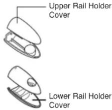
⑥ Cover the Upper and Lower Rail Holder with the Rail Holder Covers.
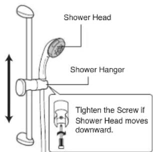
⑦ Adjust the Shower Hanger at the required level and hang the Shower Head as shown in diagram below.
3. TEST OPERATION
-
• Before switch "ON" electricity check the wiring.
-
Switch "ON" the Miniature Circuit Breaker (MCB) and ON/OFF DP (double pole) Switch.
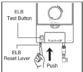
- Set the ELB of the unit to "On". (Push up the ELB Reset Lever if it is down)
- Push the ELB Test Button.
- It is normal if the ELB turns "Off" (the ELB Reset Lever falls) and push the ELB Reset Lever up.
Refer figure as shown. - Inspection on the built-in ELB (once a month) to avoid a hazard to users such as damage to property, serious injury or death.

WARNING

If the ELB Reset Lever cannot be set even if you push it up or if it soon slides down during operation, please do not use the unit and contact the authorized dealer immediately. Never fix the ELB Reset Lever forcibly with tape, etc.
-
• Turn "On" the Main Water Valve.
-
Turn clockwise the Water Volume Knob.
-
Check if water leaks from the Pipe Line.
-
• Press the Push On-Off Lever once, the ELB lamp lights and water start flowing out of the Shower Head.
- Turn the Power Control Knob / Temperature Control Knob clockwise and hot water flows out. (Adjust to suitable water temperature.)
- • Refer detail for HOW TO USE and WATER FLOW RATE ADJUSTMENT on page 15 & 16.
目录
使用电热花洒器前
页次
22
③ 清洗过滤器组件。
过滤器组件

注意
natural_image
Pure mechanical diagram of a valve or fitting with no text, numbers, or symbols4. 发生故障时
No. 3, Jalan Sesiku 15/2, Section 15, Shah Alam Industrial Site, 40200 Shah Alam, Selangor Darul Ehsan, Malaysia.
http://www.panasonic.com
TERMS AND CONDITIONS OF WARRANTY
This Warranty entitles the customer to a guaranteed free service on Panasonic products within a period of 12 months from the date of purchase. *An additional warranty of 12 months also provided for DIGITAL STILL / VIDEO / SLR CAMERA, if the warranty is being registered via online at http://club.panasonic.com.my either directly by purchaser or by Panasonic Authorized Dealer and approved by Panasonic Malaysia Sdn Bhd.
The above shall be subject to the terms and conditions listed below:
- This warranty applies to each new product purchased for domestic use in Malaysia from Panasonic Authorized Dealers supplied by Panasonic Malaysia Sdn Bhd ("Panasonic Malaysia")
- Validity of warranties registered online evidenced in printouts shall be subject to approval by Panasonic Malaysia pursuant to applicable Panasonic policies, rules, discretion or otherwise.
- Customer is required to present the original warranty card or warranty registration certificate together with the original purchase receipt for your free warranty service, failing which Panasonic Malaysia or Panasonic Authorized Service Dealers reserves the right to decline any warranty claim.
- This warranty applies to ascertained manufacturing defects arising from normal usage within the warranty period. Panasonic Malaysia or Panasonic Authorized Service Dealers will at their discretion not to impose charges for any repair and/or replacement of defective components or parts of the product. Any spare parts replaced under this warranty shall become the property of Panasonic Malaysia.
- This warranty card is not replaceable in the event of loss, theft and/or delacement.
- Panasonic Malaysia reserve the right to refuse to attend to any product installed in locations which are deemed inaccessible, inappropriate and/or hazardous to the safety and wellbeing of its service agents.
- To the extent permitted by law, no other warranties, whether express or implied, including warranties of merchantable quality and fitness for a particular purpose, shall apply to the product. Panasonic Malaysia shall not be liable for loss of profits, human injury, special, indirect or consequential damages sustained in any whatsoever proceeding, claim and/or demand resulting or attributed to the product or services rendered to it.
- All express and implied conditions herein or otherwise are subject to Panasonic Malaysia authority and discretion where and when deemed appropriate.
- Panasonic Malaysia reserves the right to bring back the product for further investigation or diagnosis and shall not reliable for any compensation claims due to whatsoever inconvenience caused to Customer.
- Customer shall pay for a minimum checking/service fees and transportation fee for any non-manufacturing defect service request to be determined by Panasonic Malaysia (if any).
- For non-Panasonic online platform purchase, customer must refer the original selleragent for 3rd party defect coverage.
- Products which do not carry valid model and serial/batch number, warranty of the product is void.
- Home service only applicable for BUILT-IN-KITCHEN (BIK) / RANGE HOOD / HOME SHOWER / CEILING FAN / VENTILATION FAN / WATER PUMP (for Ground installation only), other than this product indication, additional fees will be imposed.
(A) What is NOT covered in this warranty:
A.1. Defects caused by the attack of household pests, pets, fire, lightning, natural disasters, flood, corrosion, rusting, cosmetic damage, dent, crack, pollution, abnormal voltage or usage of generator, tampering, alteration or repair by unauthorized person, misuse, negligence, nots, accident or operation of the products contrary to the instructions contained in the products' Operating and Installation Instruction, commercial usage, including abnormal long usage hours; or, under extreme usage environmental conditions, improper testing, demonstration, maintenance, installation, product serial batch number has been removed or made illegible or has been tempered with, usage of non-genuine spare parts, adjustment or alteration of any kind.
A.2. Consumable items and accessories packaged with Panasonic products.
A.3. If the customer authorizes Panasonic Malaysia to repair the Product(s) which is not covered under the warranty (refer A.1.), the Customer must pay all the charges for all parts, shipping, and labour for the repair and return of the Product.
A.4. The content and continuity of the services through Apps are operated by respective service providers and such service may be discontinued either temporally or permanently without notice.
(B) Conditional Warranty:
B.1. DVD/VCD/Blu-ray Player: Only one replacement of Optical Pick-up Head within warranty period upon confirmation of fault. Subsequent replacement will be charged accordingly.
B.2. Range Hood: No warranty for bulb.
The English language version will be the official version for the purpose of interpretation of this warranty. Users are advised to install a lightning-resistant tool on their product. For further information, please contact our Authorize dealer.
TERMA DAN SYARAT JAMINAN
Registration No. 197601000977 (26975-W)
Customer Care Centre
Tel: 03 7953 7600 Fax: 03 7953 7606
E-mail: ccc@my.panasonic.com
Service Centre
2, 2A, 2B, Jalan Impian Emas 7,
81300 Skudai, Johor Bahru.
Tel: 07-554 3531 / 07-558 3561 Fax: 07-557 3506
Collection Centre
Kelantan
Lot 1854, Paya Bemban,
Jalan Hospital,
15400 Kota Bahru, Kelantan
Tel: 09-748 1578 Fax: 09-743 6605
Pahang / Terengganu
A303m Jalan Air Putih,
25700 Kuantan, Pahang.
Tel: 09-560 5120 Fax: 09-560 5212
Sabah
Lot. 6, Lrg Mangga 1,
BDC/Milek Perkasa Ind. Estate,
Kolombong, 88450 Kota Kinabalu, Sabah.
Tel:088-428 713 Fax:088-437 543
Sarawak
Lot 3293, Jalan Kwong Lee Bank.
Lorong Sebor, 93450 Kuching
Tel: 082-336 126 / 336 326
Fax:082-482 660
Negeri Sembilan/Perak/Melaka, visit our website: http://www.panasonic.com/my/support/service-centre.html for our nearest Authorised Service Centre.
| THIS WARRANTY CARD IS TO BE RETAINED BY CUSTOMER. FOR WARRANTY SERVICE, PRESENT THIS WARRANTY CARD WITH ORIGINAL PURCHASE RECEIPT | ||
| Customer's Name :Address :E-mail Address : | Date of PurchaseDate Month Year(To be completed by dealer) | |
| Tel No. | House : | Dealer's name and address (Stamp) |
| Handphone : | ||
| Product | ||
| Model | ||
| Serial No. / BatchNo. | ||
The customer's data or personal information collected is governed in accordance to Personal Data Protection Act 2010 (PDPA) and applicable personal data protection policy. This policy may be reviewed from time to time and obtain detailed & updated version, please refer to Panasonic Malaysia website www.panasonic.com.my
- PANDUAN KEROSAKAN
- Nota
- Pendawaian elektrik
- SAFETY INSTRUCTIONS
- SAFETY INSTRUCTIONS
- WARNING
- Stop using the Unit when any abnormality/failure occurs and turn "OFF" the Miniature Circuit Breaker (MCB). (Risk of smoke/fire/electric shock/scalding)
- The Unit must be earthed.
- CAUTION
- HOW TO USE ELECTRIC HOME SHOWER
- HOW TO USE
- Temperature setting
- DH-3MS1
- DH-3MT1
- WATER FLOW RATE ADJUSTMENT
- How to adjust to maximum water flow rate.
- MAINTENANCE
- Main Body cleaning.
- Shower Head cleaning.
- Filter Unit Cleaning (Filter Unit is fixed to Filter Knob)
- TROUBLESHOOTING
- SPECIFICATION
- HOW TO INSTALL ELECTRIC HOME SHOWER
- BEFORE INSTALLATION
- HOW TO INSTALL
- How to fix Electric Home Shower.
- Electric wiring
- Earth Rod
- Piping installation procedure
- How to fix the Front Plate
- Note:
- Shower Hanger installation.
- TEST OPERATION
- 目录
- 使用电热花洒器前
- 发生故障时
- TERMS AND CONDITIONS OF WARRANTY
- What is NOT covered in this warranty:
- Conditional Warranty:
- TERMA DAN SYARAT JAMINAN
- Service Centre
- Collection Centre
Brand : PANASONIC
Model : DH-3MS1
Category : Water heater