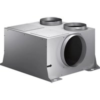
AR400130 - Fan GAGGENAU - Free user manual and instructions
Find the device manual for free AR400130 GAGGENAU in PDF.


| Product type | Extraction fan |
| Brand | Gaggenau |
| Model | AR400130 |
| Category | Fan |
| Weight | 7.3 kg |
| Dimensions (estimated) | Height: 250 mm, Width: 350 mm, Depth: 350 mm |
| Installation | Indoor wall mounting |
| Electrical connection | Via 5 m connection cable supplied with the hood |
| Power supply | 230 V ~, 50 Hz |
| Power | 150 W (estimated) |
| Material | Anti-corrosion treated metal |
| Use | Extraction of stale air, compatible with range hoods |
| Maintenance | Clean with a damp cloth, disconnect power |
| Safety | Disconnect the device before any intervention; repairs by a specialist only |
| Compliance | Applicable safety provisions |
| Warranty | 2 years (parts and labor) |
| Accessories included | Dowels and screws for solid masonry |
| Duct diameter | 150 mm (estimated) |
| Ambient temperature | 0 to 40 °C |
| Protection rating | IPX4 (estimated) |
Frequently Asked Questions - AR400130 GAGGENAU
User questions about AR400130 GAGGENAU
0 question about this device. Answer the ones you know or ask your own.
Ask a new question about this device
Download the instructions for your Fan in PDF format for free! Find your manual AR400130 - GAGGENAU and take your electronic device back in hand. On this page are published all the documents necessary for the use of your device. AR400130 by GAGGENAU.
USER MANUAL AR400130 GAGGENAU
natural_image
Technical diagram of a mechanical housing with bolted components and a directional arrow indicating movement (no text or symbols)natural_image
3D diagram of a mechanical assembly with circular components and housing, no visible text or symbols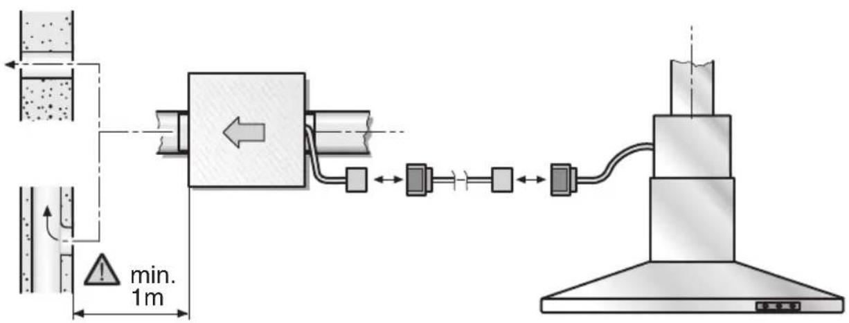
This appliance conforms to the relevant safety regulations.
Repairs should only be carried out by qualified specialists.
Improperly executed repairs can give rise to significant hazards for the user.
⚠️ Note down the type designation of the external fan in the extractor hood operating instructions.
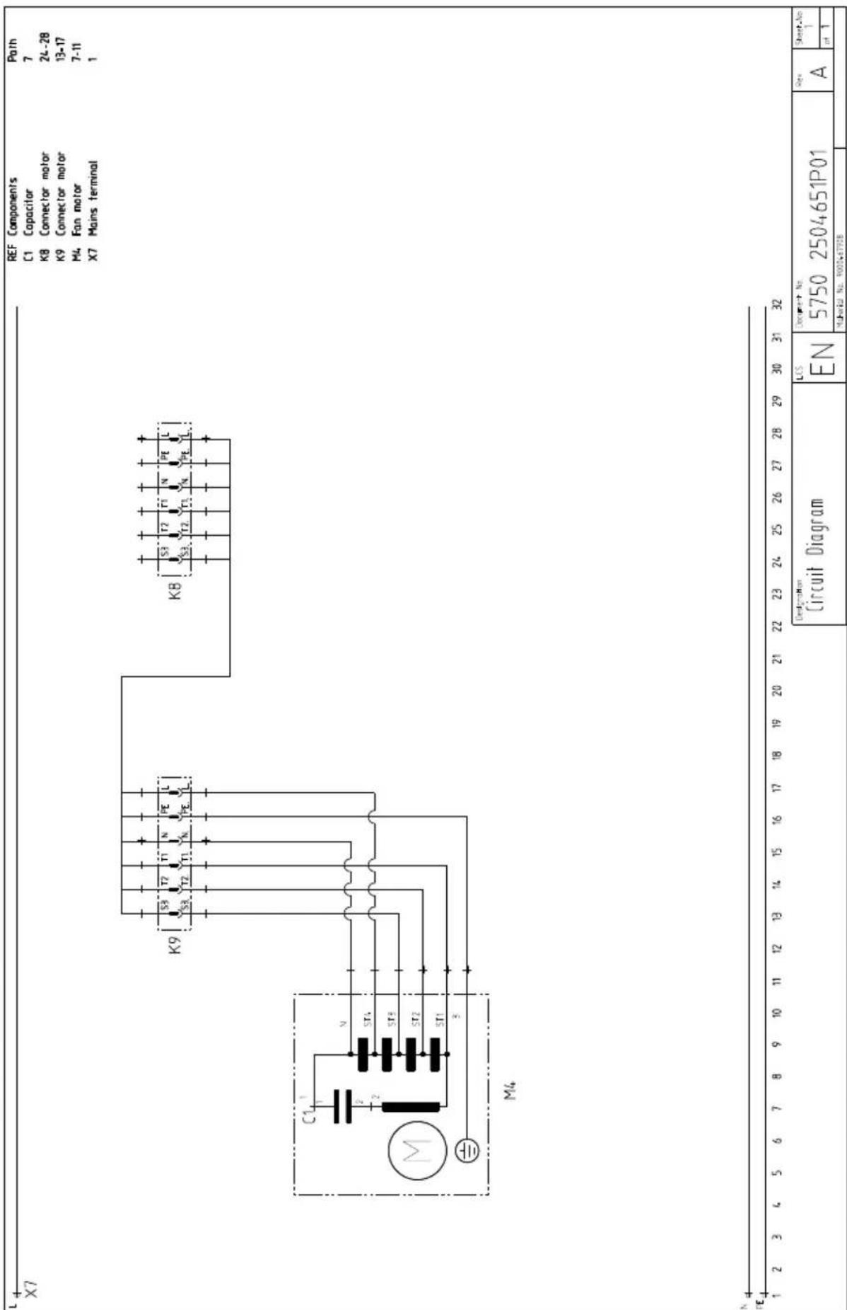
⚠ The appliance should only be connected up to the mains and taken into use by a qualified specialist.
⚠️ Before carrying out repairs or maintenance, isolate the fan. To do this, disconnect the plug-and-socket connection of the electric cable which is connected to the extractor hood or disconnect the extractor hood power cord from the power supply.
⚠️If the connecting cable for this appliance is damaged, the cable must be replaced by the manufacturer or his customer service or a similarly qualified person in order to prevent serious injury to the user.
⚠️ Old appliances are not worthless rubbish. If they are disposed of in an environment-friendly manner, valuable raw materials can be recovered for use again. Before you dispose of an old appliance, make sure that it has been rendered inoperative.
⚠️ Your new appliance was protected on its way to you by the packaging. None of the materials cause pollution to the environment and all can be recycled for use again. Please help to protect the environment and dispose of the packaging in an environment-friendly manner.
You can obtain information about the best method disposing of old appliances and packaging from your dealer or local municipal council.
Prior to installation
The exhaust air must not be removed via a functioning smoke or exhaust-gas flue or via a duct which is used to ventilate a fireplace in the installation room.
Observe the official and statutory regulations for the removal of exhaust air (e.g. Landesbauordnungen)..
Removal of exhaust air via a non-functioning smoke or exhaust-gas flue requires the consent of a heating engineer.
If the extractor hood is operating in exhaust-air mode at the same time as a flue-type heater (e.g. gas, oil or solid-fuel heater, instantaneous water heater, boiler), there must be an adequate air supply which the fireplace requires for combustion.
Safe operation is possible if the partial vacuum in the installation room of the fireplace does not exceed 4 Pa (0.04 mbar).
This can be achieved if the combustion air is able to flow through non-lockable openings, e.g. in doors, windows and in conjunction with an air supply/air-intake wall box or by other technical procedures such as reciprocal interlocking.
If the air supply is inadequate, there is a risk of poisoning caused by combustion gases being drawn back into the room.
An air supply/air-intake wall box alone does not ensure compliance with the limiting value.
Note: When assessing the air supply, always take into account the entire ventilation system in the house. This rule does not apply when using cooking appliances, e.g. hob or gas cooker.
⚠️Attach the inner wall fan inside the building only, but not in living rooms.
When attaching the inner wall fan, ensure that it is accessible for maintenance and repairs.
⚠ The plug-and-socket connections of the electric cables must be located inside the building.
Preparing the wall
⚠️RISK OF INJURY, DAMAGE TO PROPERTY
Before drilling the holes for the designated installation location, check for concealed electrical cables and other lines.
☐ The wall must be level and vertical.
☐ The enclosed screws and wall plugs are suitable for solid brickwork. Use the appropriate fixing materials for other wall structures (e.g. plaster board, porous concrete, poroton bricks). Ensure that the wall has adequate load bearing capacity.
☐ Ensure that the depth of the drilled holes corresponds with the length of the screws.
☐ Ensure that the wall plugs are secure.
Weight: 7,3 kg.
We reserve the right to construction changes within the context of technical development.
Installation
-
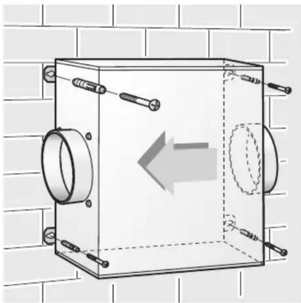
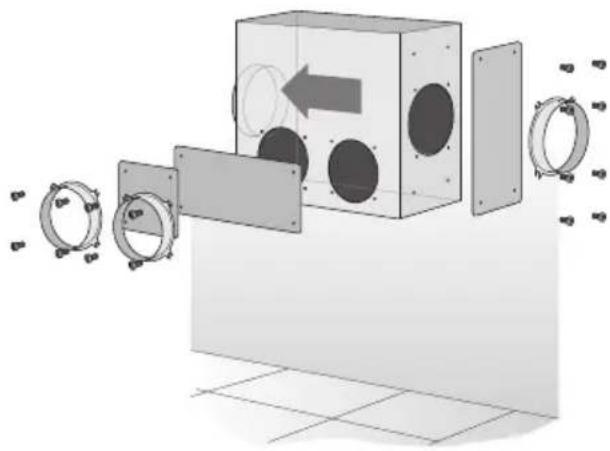
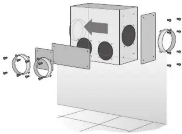
Hold the fan on the wall. Note the direction of the air conduction.
-
Mark the 4 mounting boreholes.
-
Drill the 4x 8 mm ∅ mounting boreholes. Insert wall plugs and screw the fan to the wall.
⚠ The fan is connected to the extractor hood with the \~ 5 m extension cable enclosed with the extractor hood.
-
Connect the pipe from the fan to the extractor hood and feed to the outside.
-
Connect the fan to the extractor hood with the extension cable.
⚠ The additional cover on the plug must always be attached and closed for safety reasons.
natural_image
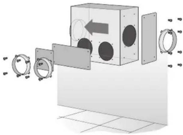
Technical diagram of a mechanical housing with bolted components and an arrow indicating direction (no text or symbols)Variable connection options:
natural_image
3D diagram of a mechanical assembly with housing, rollers, and mounting holes (no text or symbols)
natural_image
Technical line drawing of a rectangular mechanical housing with bolted components and an arrow indicating direction (no text or symbols)natural_image
3D diagram of a mechanical assembly with housing, rollers, and directional arrow (no text or symbols)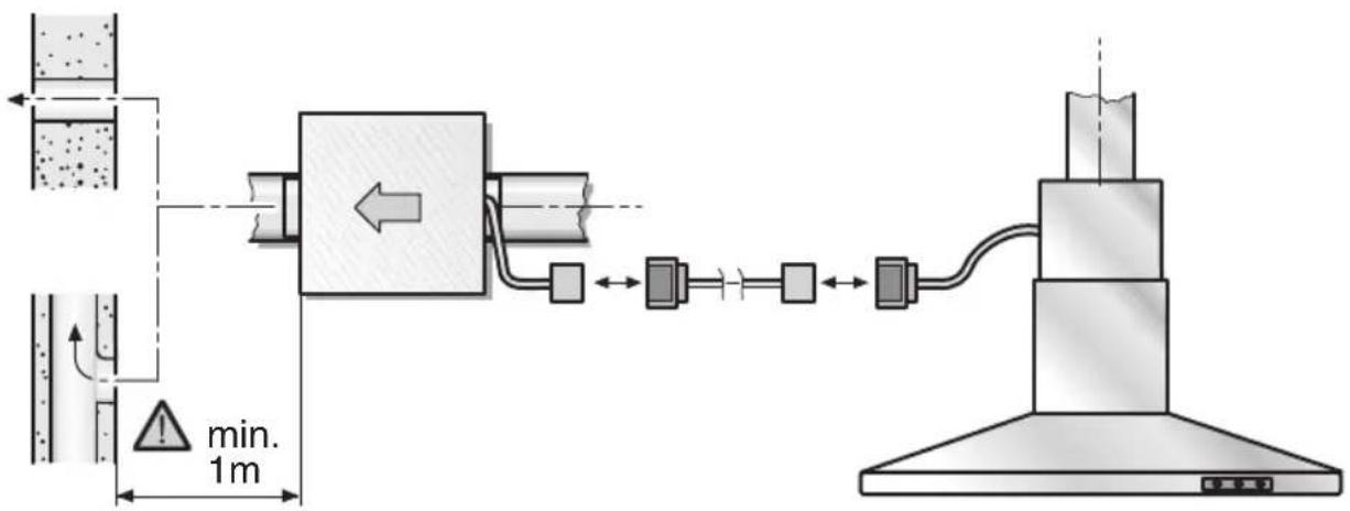
natural_image
Technical diagram of a mechanical housing with bolted components and a directional arrow indicating movement (no text or symbols)natural_image
3D diagram of a mechanical assembly with housing, rollers, and directional arrow (no text or symbols)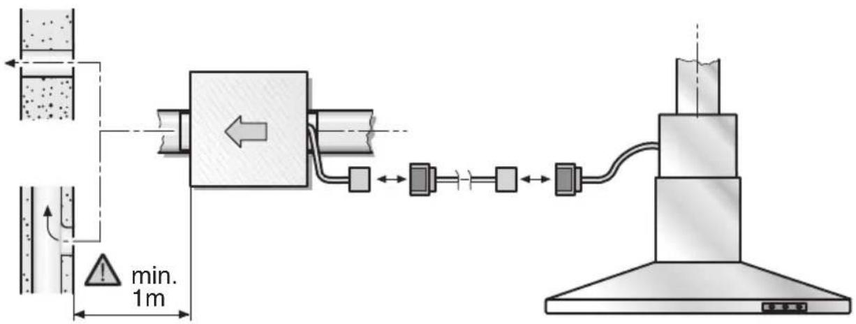
natural_image
Technical line drawing of a mechanical housing with bolted components and a directional arrow indicating movement (no text or symbols)natural_image
3D diagram of a mechanical assembly with housing, rollers, and mounting brackets (no text or symbols)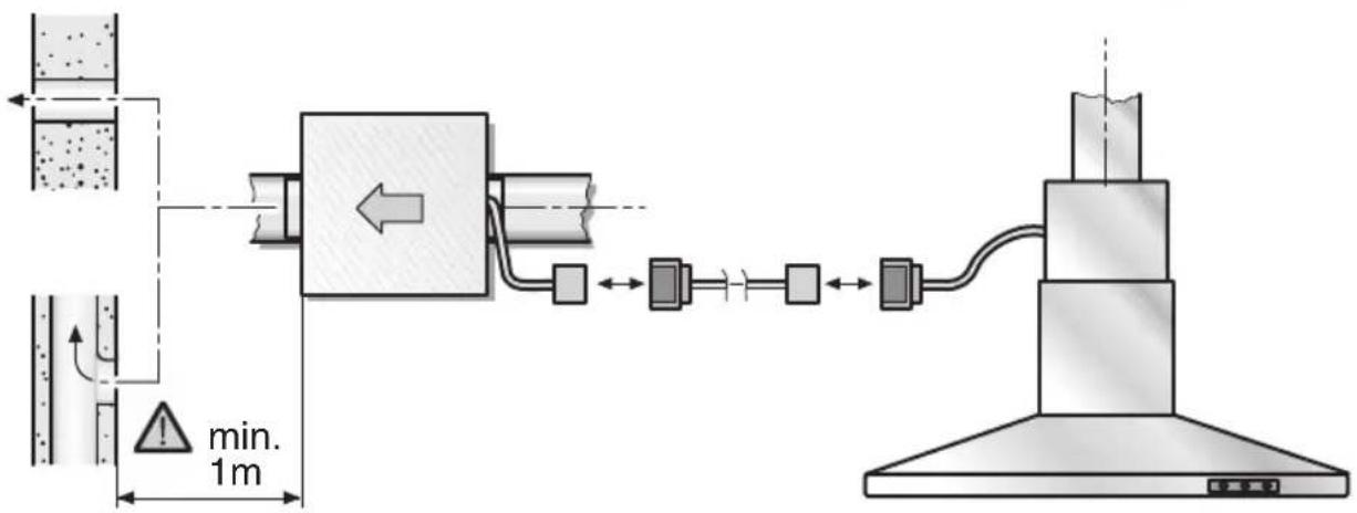
natural_image
Technical diagram of a mechanical housing with bolted components and an arrow indicating direction (no text or symbols)natural_image
3D diagram of a mechanical assembly with housing, rollers, and mounting holes (no text or symbols)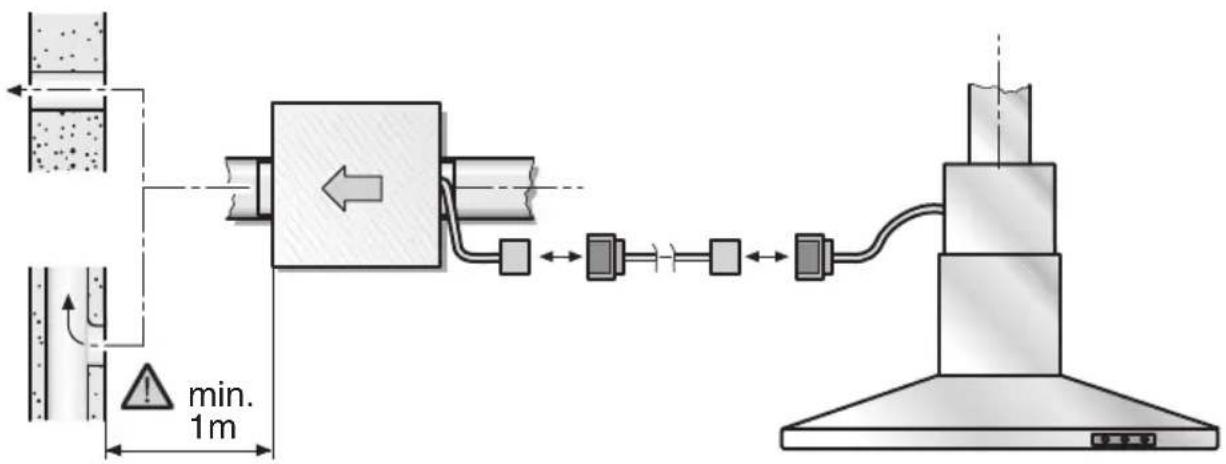
natural_image
Technical diagram of a mechanical housing with bolted components and an arrow indicating direction (no text or symbols)natural_image
3D diagram of a mechanical assembly with housing, rollers, and directional arrow (no text or symbols)
natural_image
Technical line drawing of a rectangular mechanical housing with bolted components and an arrow indicating direction (no text or symbols)Olika anslutningsalternativ:
natural_image
3D diagram of a mechanical assembly with housing, rollers, and directional arrow (no text or symbols)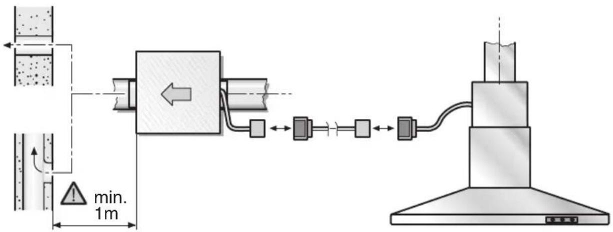
natural_image
Technical line drawing of a rectangular mechanical housing with bolted components and an arrow indicating direction (no text or symbols)Variable tilslutningsmuligheder:
natural_image
3D diagram of a mechanical assembly with housing, rollers, and mounting brackets (no text or symbols)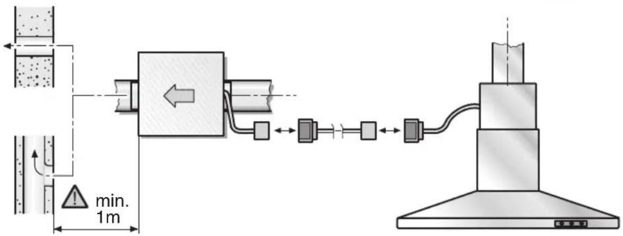
natural_image
Technical line drawing of a rectangular mechanical housing with bolted components and an arrow indicating direction (no text or symbols)natural_image
3D diagram of a mechanical assembly with housing, rollers, and mounting holes (no text or symbols)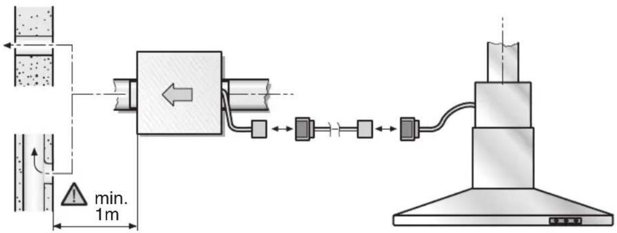
Tärkeitä ohjeita
natural_image
Technical line drawing of a rectangular mechanical housing with bolted components and an arrow indicating direction (no text or symbols)natural_image
Technical diagram of a rectangular mechanical housing with bolted components and a circular component, mounted on a brick wall (no text or symbols)natural_image
3D diagram of a mechanical assembly with housing, rollers, and mounting holes (no text or symbols)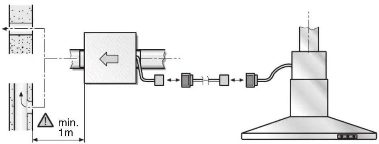
natural_image
Technical line drawing of a mechanical housing with bolted components and an arrow indicating direction (no text or symbols)natural_image
3D diagram of a mechanical assembly with circular components and mounting brackets, no visible text or symbols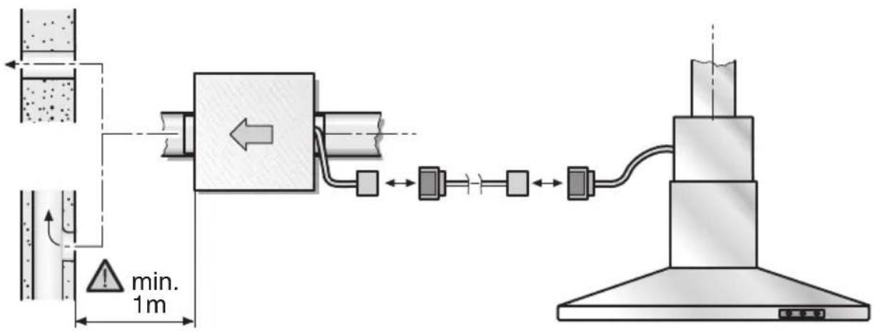
natural_image
Technical line drawing of a rectangular mechanical housing with bolted components and an arrow indicating direction (no text or symbols)natural_image
3D diagram of a mechanical assembly with housing, rollers, and directional arrow (no text or symbols)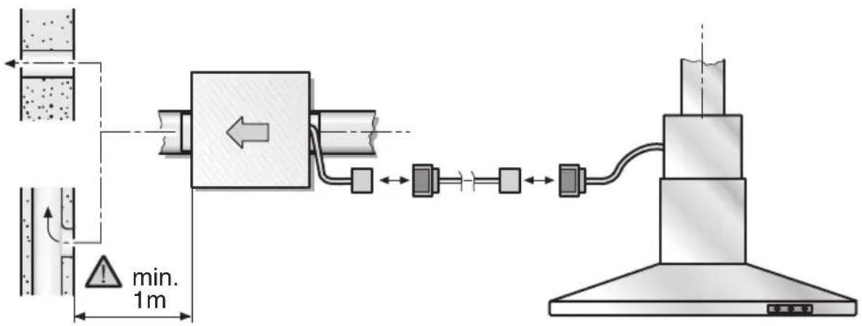
natural_image
Technical line drawing of a mechanical housing with bolted components and an arrow indicating direction (no text or symbols)natural_image
3D diagram of a mechanical assembly with housing, rollers, and directional arrow (no text or symbols)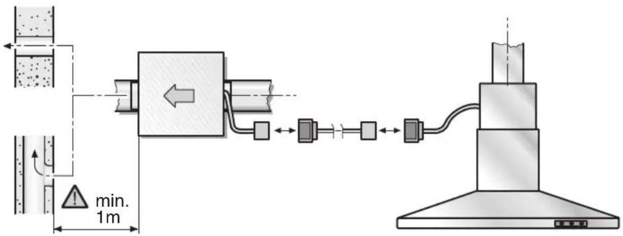
natural_image
Technical line drawing of a rectangular mechanical housing with bolted components and an arrow indicating direction (no text or symbols)natural_image
3D diagram of a mechanical assembly with housing, rollers, and directional arrow (no text or symbols)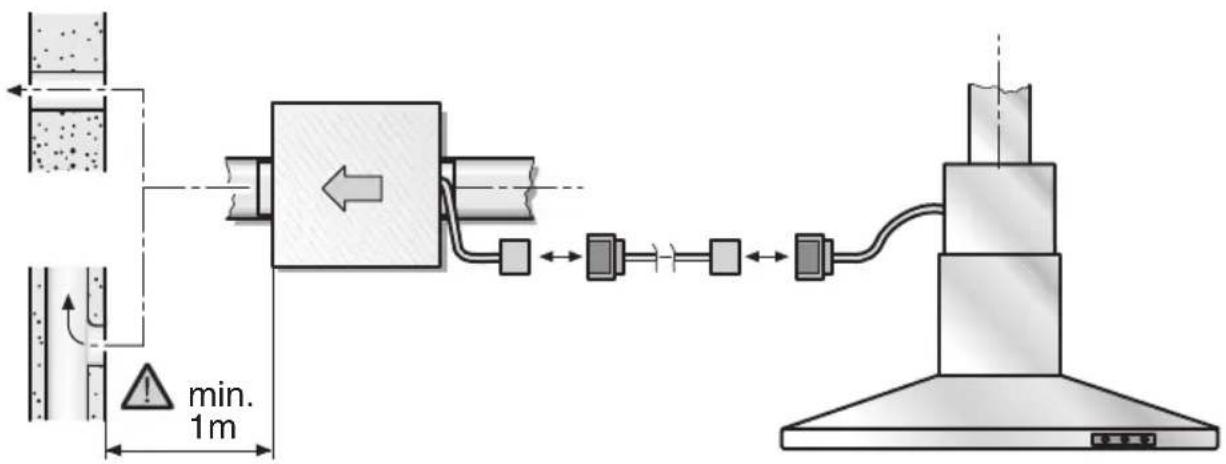
Notizen
The reproduction, transmission or use of this document or its contests is not permitted without express written authority. Offenders will be liable for damages. All rights including rights created by patent grant or registration of a utility model or design are reserved. Copyright reserved.
- Improperly executed repairs can give rise to significant hazards for the user.
- Prior to installation
- Observe the official and statutory regulations for the removal of exhaust air (e.g. Landesbauordnungen)..
- If the air supply is inadequate, there is a risk of poisoning caused by combustion gases being drawn back into the room.
- Preparing the wall
- ⚠️RISK OF INJURY, DAMAGE TO PROPERTY
- Weight: 7,3 kg.
- Installation
- Tärkeitä ohjeita
- Notizen
Brand : GAGGENAU
Model : AR400130
Category : Fan