
Vitronic 18 W - Water filter OASE - Free user manual and instructions
Find the device manual for free Vitronic 18 W OASE in PDF.

| Brand | Oase |
| Model | Vitronic 18 W |
| Product type | UVC clarifier for pond |
| Power consumption | 18 W |
| Connection voltage | 220-240 V AC, 50/60 Hz |
| Mains cable length | 5 m |
| Protection rating | IP24 (protected against water splashes) |
| UVC lamp | 18 W TC-S (UV-C) |
| Maximum flow rate | 3500 l/h |
| Maximum operating pressure | 0.6 bar |
| Connections | 3 × G1 1/2 |
| Hose diameter | 25, 32, 38 mm |
| Maximum pond volume (without fish) | 20 m³ |
| Maximum pond volume (with fish) | 10 m³ |
| Maximum pond volume (with koi) | 5 m³ |
| Dimensions (L × W × H) | 529 × 186 × 130 mm |
| Weight | 2.1 kg |
| Permissible water values (pH) | 6.8 - 8.5 (freshwater) |
| Water temperature | +4 to +35 °C |
| Main function | Elimination of algae, bacteria and germs by UVC radiation |
| Wear parts | UVC lamp, quartz glass, O-ring |
| Service life of the UVC lamp | 8000 hours (approx. one season) |
| Maintenance | Cleaning of quartz glass, lamp replacement |
| Safety | Do not use without water flow, disconnect before maintenance |
| Frost protection | Remove and store frost-free |
Frequently Asked Questions - Vitronic 18 W OASE
User questions about Vitronic 18 W OASE
0 question about this device. Answer the ones you know or ask your own.
Ask a new question about this device
Download the instructions for your Water filter in PDF format for free! Find your manual Vitronic 18 W - OASE and take your electronic device back in hand. On this page are published all the documents necessary for the use of your device. Vitronic 18 W by OASE.
USER MANUAL Vitronic 18 W OASE
natural_image
Three black industrial sensors with metallic connectors and ports, shown from different angles (no text or symbols visible)Vitronic
11 W, 18 W, 24 W, 36 W, 55 W
EN Operating instructions
FR Notice d'emploi
Vitronic 11 W 18 W, 24 W, 36 W, 55 W
Vitronic 18 W, 24 W, 36 W, 55 W


natural_image
Simple line drawing of a checkmark and a vertical wall-mounted device (no text or symbols)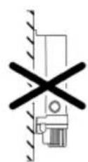
VTC000€


VTC0007
Vitronic 18 W, 24 W, 36 W
Vitronic 18 W, 24 W, 36 W

VTC0011
Inbetriebnahme
Vitronic 18 W, 24 W, 36 W, 55 W

VTC0010
Vitronic 18 W, 24 W, 36 W, 55 W
So gehen Sie vor:
natural_image
Technical line drawing of a mechanical device with no visible text or symbolsVitronic 18 W, 24 W, 36 W, 55 W

natural_image
Mechanical assembly diagram showing a hand operating a tool with a magnified inset highlighting the component (no text or symbols present)VTC0003
Gerätekopf einbauen
DE
So gehen Sie vor:
Vitronic 18 W, 24 W, 36 W, 55 W

VTC0005
VTC0008
Lagern/Überwintern
▶ Disconnect all electrical units in the water from the power supply before reaching into the water. Otherwise there is a risk of injuries or death by electrocution.
This unit can be used by children aged 8 and above and by persons with reduced physical, sensory or mental capabilities or lack of experience and knowledge if they are supervised or have been instructed on how to use the unit in a safe way and they understand the hazards involved. Do not allow children to play with the unit. Only allow children to carry out cleaning and user maintenance under supervision.
EN
Safety information
Electrical connection
- Special regulations apply to electrical installation in outdoor areas. Only allow a qualified electrician to perform the electrical installation.
— The qualified electrician has the required professional training, knowledge and skills to perform electrical installations in outdoor areas. The qualified electrician can detect potential risks and adheres to regional and national standards, regulations and directives.
— For your own safety, please consult a qualified electrician. - Only connect the unit if the electrical data of the unit and the power supply match.
- Only plug the unit into a correctly installed outlet. Ensure that the unit is fused for a rated fault current of max. 30 mA by means of a fault current protection device.
- Extension cables and power distributors (e.g. outlet strips) must be suitable for outdoor use (splash-proof).
- Protect open plugs and sockets from moisture.
Safe operation
- Do not use the unit, if electrical lines or the housing are damaged.
- A damaged connection cable cannot be replaced. Dispose of the unit.
- Do not carry or pull the unit by its power cable.
- Route lines so that they are protected from damage and nobody can trip over them.
- Never make technical modifications to the unit.
- Only carry out work on the unit that is described in this manual.
- Only use original spare parts and accessories.
Intended use
Only use the product described in this manual as follows:
- For cleaning garden ponds.
- For operation with clean water.
- Operate the product in compliance with the technical data. (→ Technical data)
The following restrictions apply to the unit:
- This product is not suitable for general lighting, but is only intended for the purpose described here.
- Never operate the UVC lamp outside the casing or use it for any other purpose. The UVC radiation is harmful to the eyes and skin even in small doses.
- Do not use for commercial or industrial purposes.
- Never run the unit without water.
- Never use the unit with fluids other than water.
- Not to be used for sterilizing drinking water or other fluids.
- Do not use in conjunction with chemicals, foodstuff, easily flammable or explosive substances.
Product description
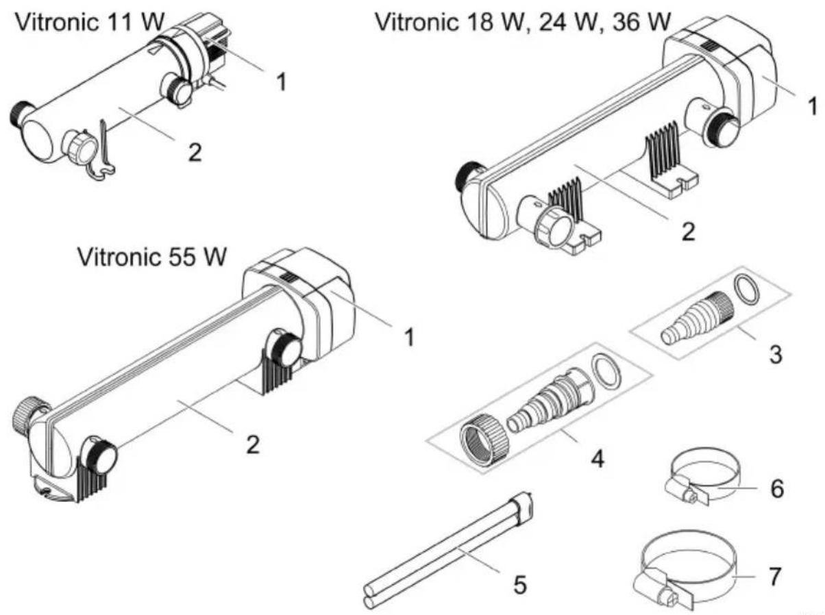
Scope of delivery
EN
VTC0001
Vitronic 11 W 18 W, 24 W, 36 W, 55 W
| Description | Quantity | Quantity | |
| 1 | Unit head | 1 | 1 |
| 2 | Casing | 1 | 1 |
| 3 | Transparent stepped hose adapter with O-ringFor hose diameter 19 ... 38 mm | 2 | - |
| 4 | Transparent stepped hose adapter with union nut and flat sealFor hose diameter 25 ... 38 mm | - | 2 |
| 5 | UVC lampVitronic 11 W: pre-installed at factory | - | 1 |
| 6 | Hose clip 20 ... 32 mm | - | 2 |
| 7 | Hose clip 35 ... 50 mm | - | 2 |
Properties
The UV radiation of the UVC clarifier removes suspended algae, bacteria and germs. The UVC clarifier is integrated in the water circuit, ideally upstream of a pond filter.
Symbols on the unit
| IP 24 | The unit is protected against splash water and against contact with dangerous components. |
| Dangerous UVC radiation. | |
| Protect the unit from direct sunlight. | |
| The lamp is suitable for direct fastening to normally flammable mounting surfaces. | |
| Protect the unit from freezing temperatures. | |
| Do not dispose of the unit with normal household waste. | |
| Read the operating instructions. |
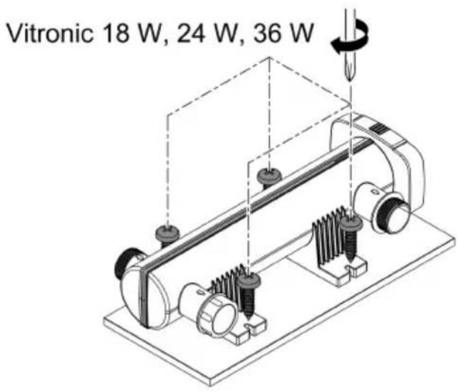
Installation and connection
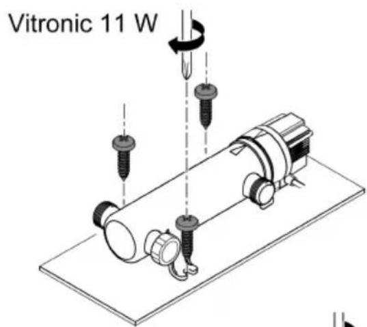
Vitronic 11 W
- It is not necessary to remove the unit head in order to fasten the casing on the ground.
- The UVC lamp has been pre-installed at the factory.
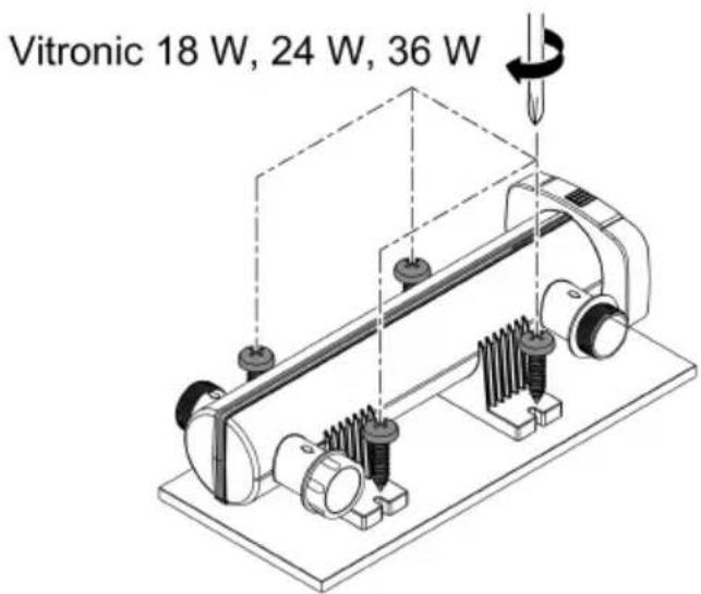
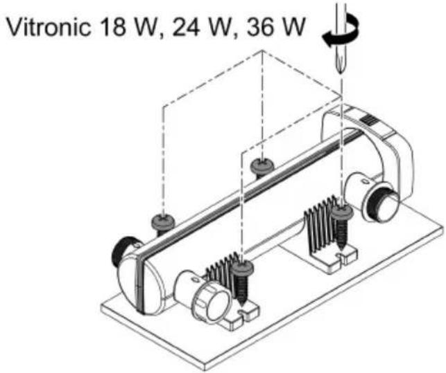
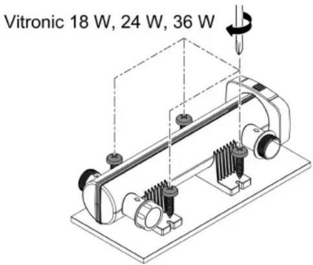
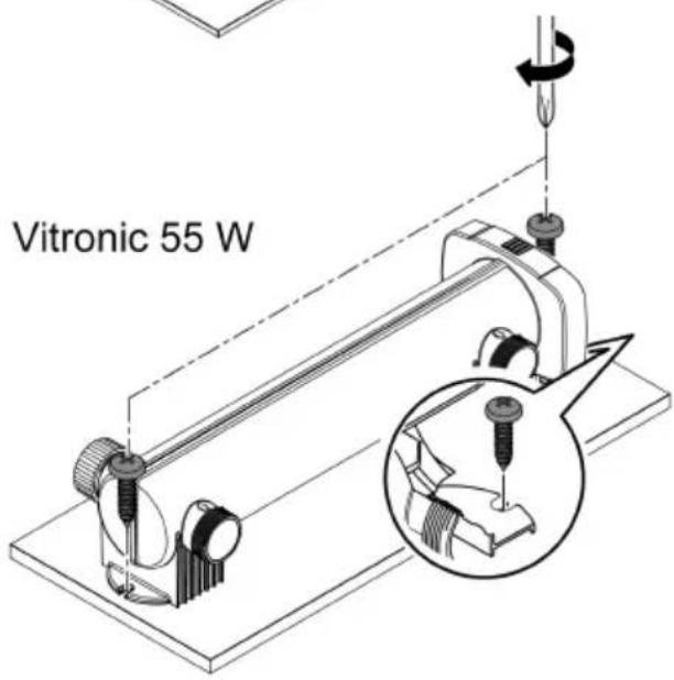
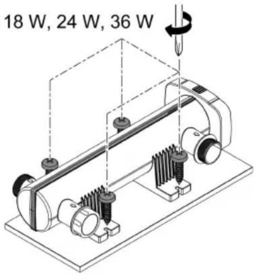
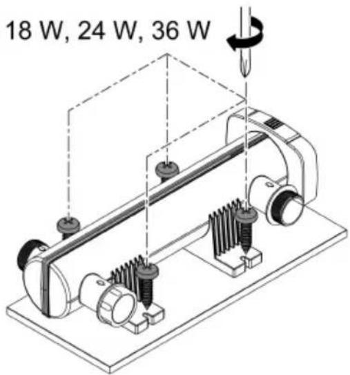
Vitronic 18 W, 24 W, 36 W, 55 W
- It is necessary to remove the unit head before fastening the casing on the ground. (→ Dismantling the unit head)
- The UVC lamp was not pre-installed at the factory. Insert the UVC lamp in the unit head before reinstalling the unit head. (→ Cleaning the quartz glass / Replacing the UVC lamp)
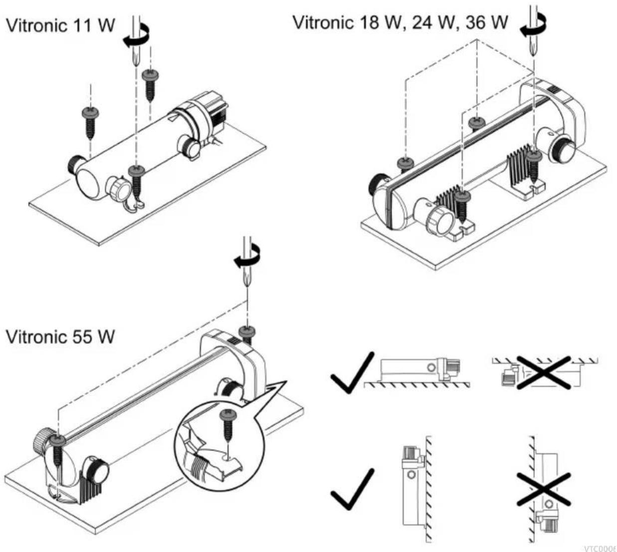
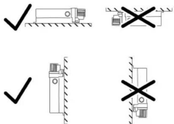
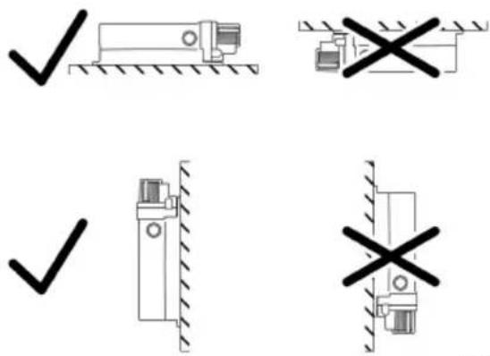
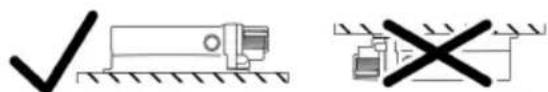
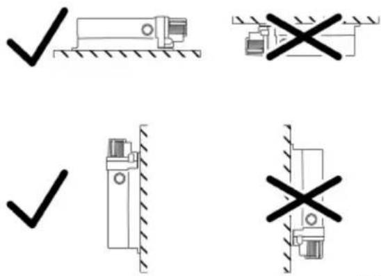
Installing the unit
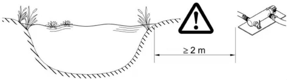
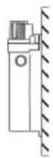
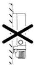
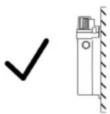
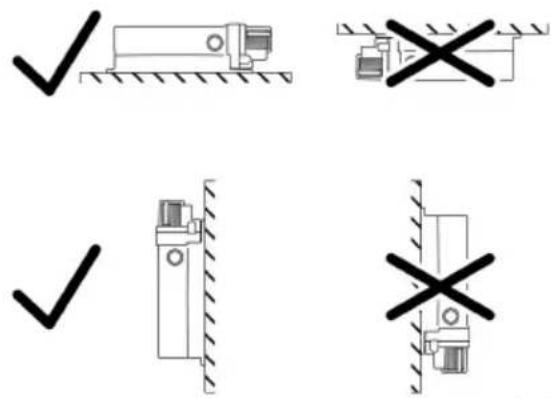
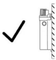
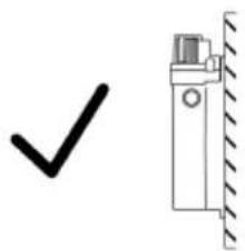
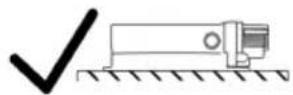
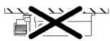
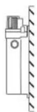
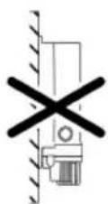
• Install the unit at least 2 m from the edge of the pond.
- Only install the unit in the permitted positions. This ensures fault-free operation.
- Allow sufficient space for carrying out maintenance work.
VTC001


natural_image
Two diagrams showing a truck with checkmark and cross symbols, no text or labels present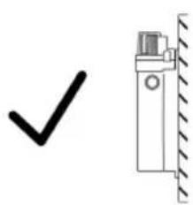
natural_image
Simple line drawing of a checkmark and a vertical wall-mounted device (no text or symbols)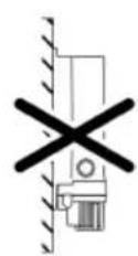
VTC000€
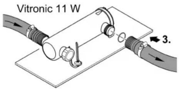
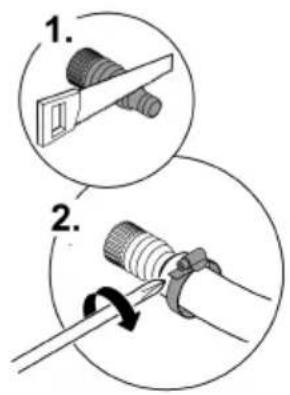
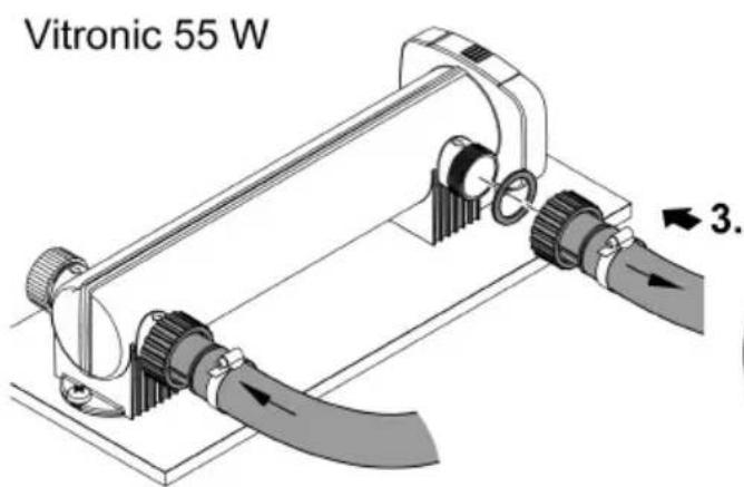
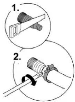
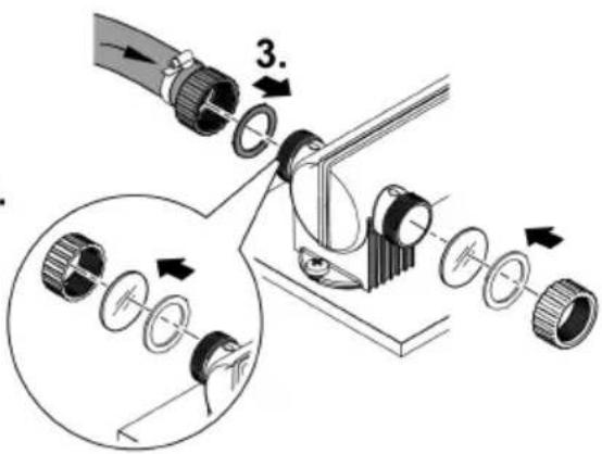
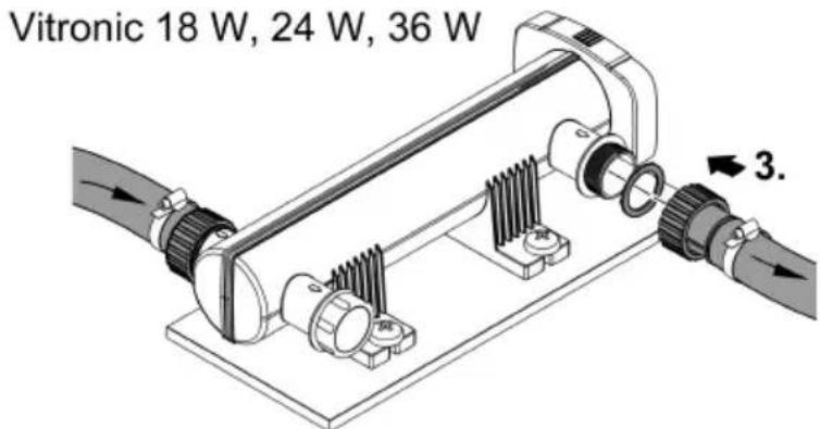
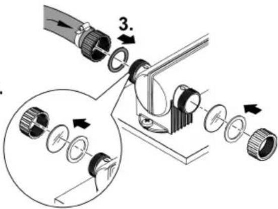
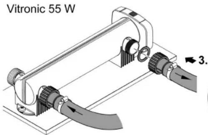
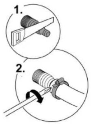
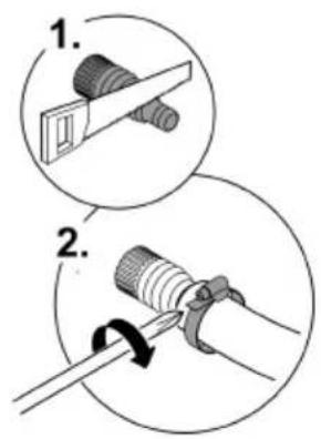
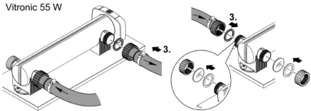
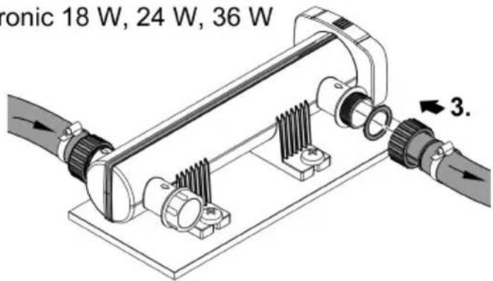
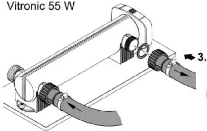
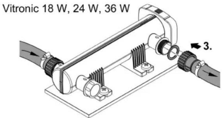
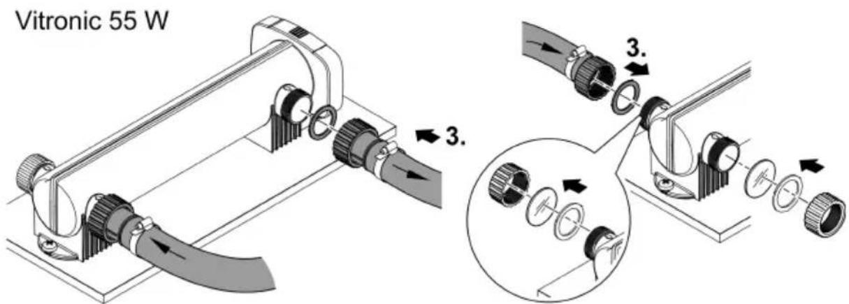
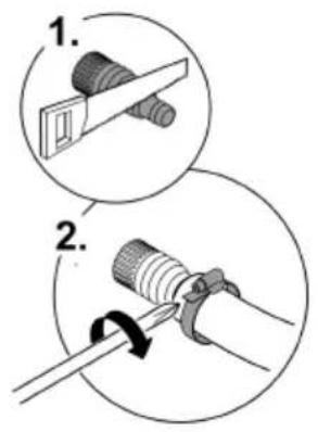
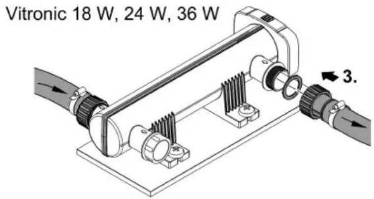
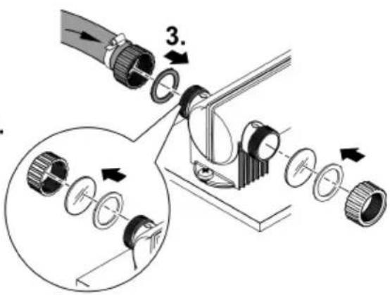
Establishing the connections
- Use hoses that are suitable for a pressure of at least 1 bar.
- Shorten the stepped hose adapters according to the hose diameter in use.
- Secure the hose with a hose clip.
- Hand-tighten the union nut of the stepped hose adapter.
- Screw the stepped hose adapter with the flat seal or O-ring onto the connection so that the connection is leak-tight.
- You can choose from the two connections arranged opposite each other to ensure that the hose is routed optimally.
- Use the closing cap to close the connection that is not in use.
— Vitronic 55 W: The closing cap has an inspection glass for function checks.


VTC0007
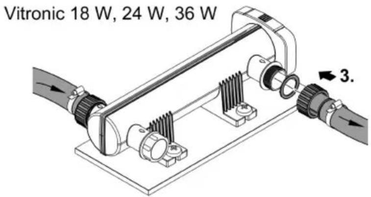
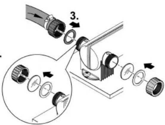
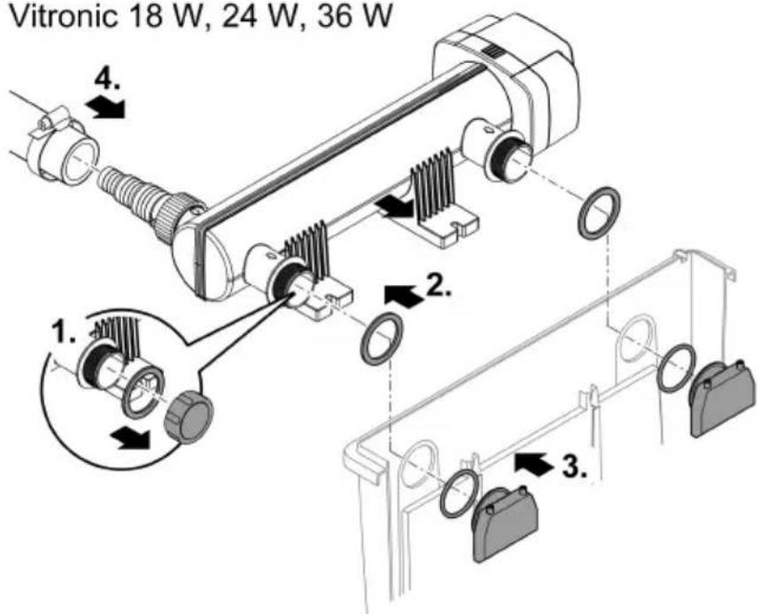
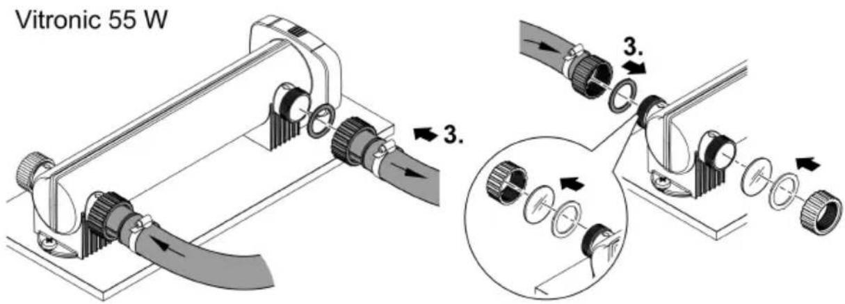
Connecting the unit to the flow-through filter.
Vitronic 18 W, 24 W, 36 W
The unit is suitable for connection to flow-through filters. Both outlet sockets are screwed to the inlet nozzles on the flow-through filter. Adhere to the instructions for use of the flow-through filter.
How to proceed:
- Unscrew the closing cap.
- Guide the two outlet sockets with the flat seal through the two holes in the container wall of the flow-through filter.
- Screw the inlet nozzle with the O-ring onto the outlet socket and hand-tighten the inlet nozzle.
- Connect the supply hose to the inlet socket. (→ Establishing the connections)
Vitronic 18 W, 24 W, 36 W

VTC0011
Commissioning/start-up
Start-up sequence:
-
Switch on the pump and wait until the casing of the UVC clarifier is filled with water.
-
Switch on the UVC clarifier.
— Never run the UVC clarifier without water flowing through.
-
Check the UVC clarifier function.
-
Check all connections for leaks.
Switching ON/OFF
- Switching on: Plug the power plug into the outlet.
- The unit switches on immediately.
- Switching off: Pull the power plug from the outlet.
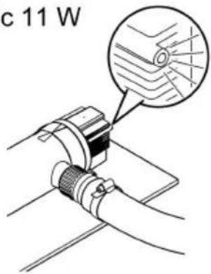
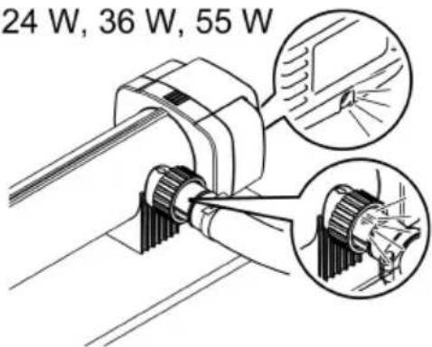
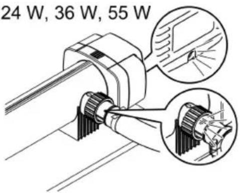
Checking the function
| Function check | Vitronic | ||
| 11 W | 18 W, 24 W, 36 W | 55 W | |
| The function display is lit when the UVC lamp is switched on. | √ | √ | √ |
| The UV light shines through the transparent stepped hose adapter when the UVC lamp is switched on. | × | √ | √ |
| The UV light shines through the closing cap when the UV lamp is switched on. | × | × | √ |
Vitronic 11 W
Vitronic 18 W, 24 W, 36 W, 55 W

VTC0010
Maintenance and cleaning
NOTE
Do not use aggressive cleaning agents or chemical solutions. These agents can damage the housing, impair the function of the device and harm animals, plants and the environment.
▶ Only clean the unit from the outside with clear water and a soft brush.
- Recommended cleaning agent for removing stubborn limescale deposits:
— Pump cleaning agent PumpClean from OASE.
— Vinegar- and chlorine-free household cleaning agent.
Dismantling the unit head

CAUTION
The ultra-violet radiation of the UVC lamp can burn your eyes and skin.
▶ Never operate the UVC lamp outside out the casing or in a damaged casing.
▶ Disconnect the unit from the power grid before starting any maintenance work or before replacing the UVC lamp.

CAUTION
The quartz glass and UVC lamp could break and cause cuts.
▶ Act with caution when performing work on the UVC clarifier in order to avoid cuts.
▶ Avoid shocks, impacts and abrupt movements to prevent the glass from breaking.
For safety reasons, the UVC lamp can only be turned on when the UVC clarifier is properly installed in the unit.
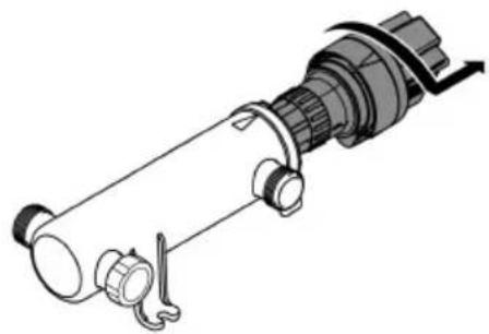
Vitronic 11 W
How to proceed:
- Turn the unit head counter-clockwise up to the stop and carefully pull it out of the casing together with the O ring.
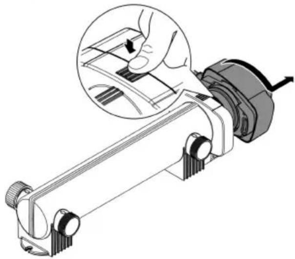
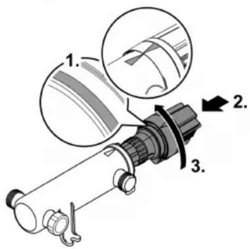
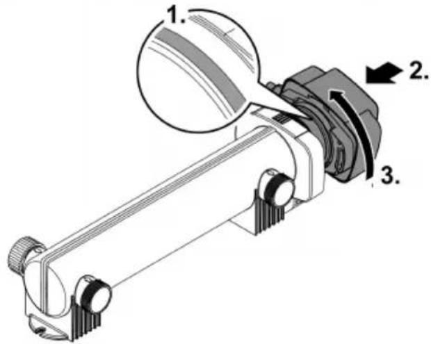
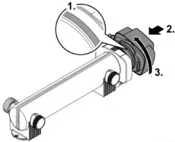
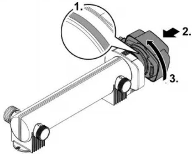
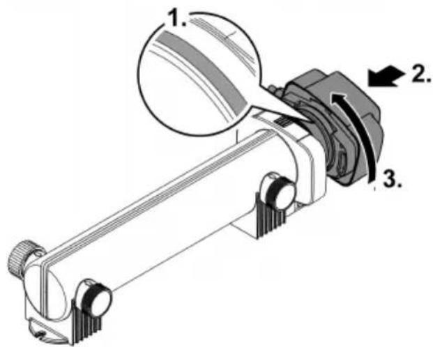
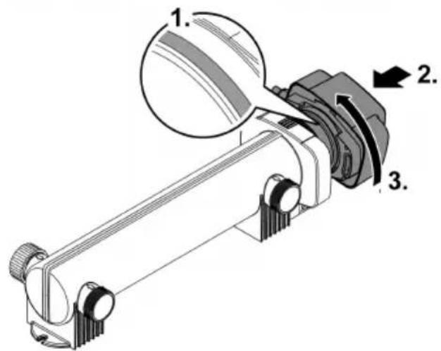
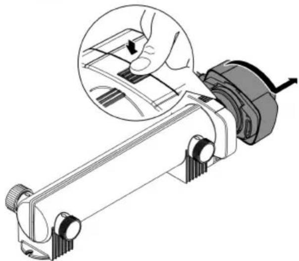
Vitronic 18 W, 24 W, 36 W, 55 W
How to proceed:
- Push down the snap-fit hook, then turn the unit head counter-clockwise up to the stop and carefully pull the unit head out of the casing.
Vitronic 11 W
natural_image
Technical line drawing of a mechanical device with no visible text or symbolsVitronic 18 W, 24 W, 36 W, 55 W
natural_image
Mechanical assembly diagram showing a lever mechanism with a hand adjusting a component, no text or symbols present.VTC0003
Fitting the unit head
How to proceed:
- Check the O-ring on the unit head for correct fit.
- Clean the O-ring, replace it if it is damaged.
- Carefully push the unit head into the casing up to the stop while applying slight pressure.
- While doing so, slightly turn the unit head to ensure that the tenons and the grooves of the bayonet closure mesh.
- Turn the unit head clockwise up to the stop.
Vitronic 11 W
Vitronic 18 W, 24 W, 36 W, 55 W

VTC0005
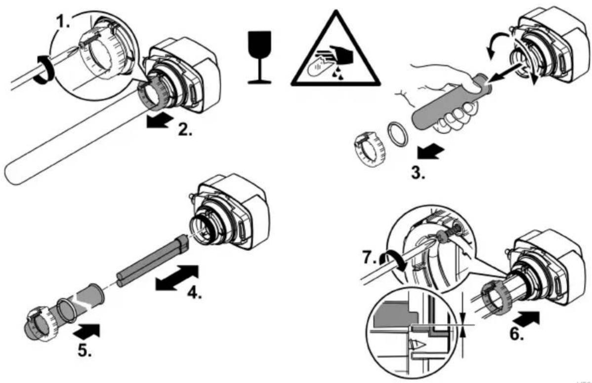
Cleaning the quartz glass / Replacing the UVC lamp
Replace the UVC lamp after no more than 8000 operating hours. With constant operation, this corresponds approximately to one pond season. This ensures optimum filtering performance.
CAUTION
The quartz glass and UVC lamp could break and cause cuts.
▶ Act with caution when performing work on the UVC clarifier in order to avoid cuts.
- Avoid shocks, impacts and abrupt movements to prevent the glass from breaking.
Prerequisite
- The unit head is removed. (→ Dismantling the unit head)
- Only use UVC lamps, the identification and power data of which correspond to the information on the type plate. (→ Technical data)
How to proceed:
- Loosen the self-tapping screw until the the screw tip is sunk into the casing of the clamping screw.
- Carefully remove the quartz glass by pulling it forward with a slight turning movement.
- Carefully push the quartz glass with the O-ring as far as the stop in the unit head during installation.
- Ensure that the O ring is located in the gap between the unit head and the quartz glass.
- Tighten the clamping screw up to the stop.
- Wipe the quartz glass with a damp cloth to remove dirt and fingerprints.
Storage/overwintering
The unit is not frost-proof and has to be removed and put into storage if freezing temperatures are expected.
How to correctly store the unit:
- Thoroughly clean the unit and replace damaged components.
- Store the unit in a dry and frost-free place.
Troubleshooting
| Malfunction | Possible cause | Remedy |
| The performance of the unit is not satisfactory | The water is extremely soiled | Remove algae and leaves from the pond |
| Replace the water in the pond | ||
| The quartz glass is soiled | Clean the quartz glass | |
| The UVC lamp has lost its filter effect | Replace the UVC lamp. The filter effect is exhausted after 8000 operating hours. | |
| The flow rate is too high | Reduce the pump output | |
| The UVC lamp does not light up | The power plug is not connected | Plug the power plug into the outlet |
| The UVC lamp is defective | Replace the UVC lamp | |
| The power connection is defective | Check the electrical connection | |
| Vitronic 55 W: The UVC clarifier has shut down due to overheating | The UVC clarifier will automatically switch on again once it has cooled down |
Technical data
| Description | Vitronic | ||||||
| 11 W | 18 W | 24 W | 36 W | 55 W | |||
| Connection voltage | V AC | 220 ... 240 | 220 ... 240 | 220 ... 240 | 220 ... 240 | 220 ... 240 | |
| Mains frequency | Hz | 50/60 | 50/60 | 50/60 | 50/60 | 50/60 | |
| Power consumption | W | 14 | 18 | 24 | 36 | 55 | |
| Length of power cable | m | 5 | 5 | 5 | 5 | 5 | |
| Protection type | IP24 | IP24 | IP24 | IP24 | IP24 | ||
| UVC lamp | Type | 11 W TC-S (UV-C) | 18 W TC-S (UV-C) | 24 W TC-S (UV-C) | 36 W TC-S (UV-C) | 55 W TC-S (UV-C) | |
| Flow rate | Max. | l/h | 1700 | 3500 | 4500 | 6000 | 8500 |
| Operating pressure | Max. | bar | 0.5 | 0.6 | 0.6 | 0.6 | 0.6 |
| Connections | 3 × G1 | 3 × G1 12 | 3 × G1 12 | 3 × G1 12 | 3 × G1 12 | ||
| Hose diameter | mm | 19, 25, 32, 38 | 25, 32, 38 | 25, 32, 38 | 25, 32, 38 | 25, 32, 38 | |
| Suitable for max. pond volume | Without fish population | m^3 | 10.0 | 20.0 | 25.0 | 40.0 | 60.0 |
| With fish population | m^3 | 5.0 | 10.0 | 12.5 | 20.0 | 30.0 | |
| Including koi carp | m^3 | 2.5 | 5.0 | 6.5 | 10.0 | 15.0 | |
| Dimensions | Length | mm | 330 | 529 | 529 | 529 | 660 |
| Width | mm | 120 | 186 | 186 | 186 | 155 | |
| Height | mm | 100 | 130 | 130 | 130 | 130 | |
| Weight | kg | 1.3 | 2.1 | 2.3 | 2.3 | 2.3 | |
Permissible water values
| Type | Fresh water, pond water | Pool water | |
| pH value | 6.8 ... 8.5 | 7.2 ... 8.3 | |
| Hardness | DH | 8 ... 15 | 8 ... 15 |
| Free chlorine | mg/l | <0.3 | <0.6 |
| Chloride content | mg/l | <250 | <250 |
| Salt content | % | <0.4 | <0.4 |
| Overall dry residue | mg/l | <50 | <50 |
| Temperature | °C | +4 ... +35 | +4 ... +30 |
EN
Wear parts
• UVC lamp, quartz glass and O-ring for quartz glass
Disposal
NOTE

Do not dispose of this unit with household waste.
▶ Dispose of the UVC lamp and the unit by using the return system provided for this purpose.
▶ Render the unit unusable by cutting the cables.

AVERTISSEMENT
Vitronic 11 W 18 W, 24 W, 36 W, 55 W
Vitronic 18 W, 24 W, 36 W, 55 W


natural_image
Simple line drawing of a checkmark and a vertical wall-mounted device (no text or symbols)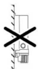
VTC000€


VTC0007
Vitronic 18 W, 24 W, 36 W
Vitronic 18 W, 24 W, 36 W, 55 W

VTC0010
Vitronic 18 W, 24 W, 36 W, 55 W
natural_image
Technical line drawing of a mechanical device with no visible text or symbolsVitronic 18 W, 24 W, 36 W, 55 W

natural_image
Mechanical assembly diagram showing a hand operating a tool with a magnified inset highlighting the component (no text or symbols present)VTC0003
Vitronic 18 W, 24 W, 36 W, 55 W

VTC0005
VTC0008
Vitronic 11 W 18 W, 24 W, 36 W, 55 W
Vitronic 18 W, 24 W, 36 W, 55 W


VTC0007
Vitronic 18 W, 24 W, 36 W
Vitronic 18 W, 24 W, 36 W

VTC0011
Ingebruikname
Vitronic 18 W, 24 W, 36 W, 55 W

VTC0010
Vitronic 18 W, 24 W, 36 W, 55 W
Zo gaat u te werk:
natural_image
Technical line drawing of a mechanical device with no visible text or symbolsVitronic 18 W, 24 W, 36 W, 55 W

natural_image
Mechanical assembly diagram showing a lever mechanism with a hand adjusting a component, no text or symbols present.VTC0003
Apparaatkop monteren
Zo gaat u te werk:
Vitronic 18 W, 24 W, 36 W, 55 W

VTC0005
VTC0008
Opslag/overwinteren
Vitronic 11 W 18 W, 24 W, 36 W, 55 W
Vitronic 18 W, 24 W, 36 W, 55 W


VTC000€


VTC0007
Vitronic 18 W, 24 W, 36 W
Vitronic 18 W, 24 W, 36 W, 55 W

VTC0010
Vitronic 18 W, 24 W, 36 W, 55 W
natural_image
Technical line drawing of a mechanical device with no visible text or symbolsVitronic 18 W, 24 W, 36 W, 55 W

natural_image
Mechanical assembly diagram showing a lever mechanism with a hand adjusting a component, no text or symbols present.VTC0003
Vitronic 18 W, 24 W, 36 W, 55 W

VTC0005
VTC0008
Vitronic 11 W 18 W, 24 W, 36 W, 55 W
Vitronic 18 W, 24 W, 36 W, 55 W


natural_image
Two technical diagrams showing a vehicle under checkmark and a truck with cross symbol (no text or labels)
natural_image
Simple line drawing of a checkmark and a vertical wall-mounted device (no text or symbols)
VTC000€

VTC0007
Vitronic 18 W, 24 W, 36 W
Vitronic 18 W, 24 W, 36 W

VTC0011
Vitronic 18 W, 24 W, 36 W, 55 W

VTC0010
Vitronic 18 W, 24 W, 36 W, 55 W
natural_image
Technical line drawing of a mechanical device with no visible text or symbolsVitronic 18 W, 24 W, 36 W, 55 W

natural_image
Mechanical assembly diagram showing a hand operating a tool with a magnified inset highlighting the component (no text or symbols present)VTC0003
Montar a cabeça
Vitronic 18 W, 24 W, 36 W, 55 W
VTC0005
PT
Armazenar/Invernar
Vitronic 11 W 18 W, 24 W, 36 W, 55 W
Vitronic 18 W, 24 W, 36 W, 55 W


natural_image
Simple line drawing of a checkmark and a vertical wall-mounted device (no text or symbols)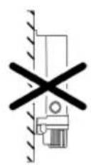
VTC000€


VTC0007
Vitronic 18 W, 24 W, 36 W
Vitronic 18 W, 24 W, 36 W

VTC0011
Messa in funzione
Vitronic 18 W, 24 W, 36 W, 55 W

VTC0010
Vitronic 18 W, 24 W, 36 W, 55 W
natural_image
Technical line drawing of a mechanical device with no visible text or symbolsVitronic 18 W, 24 W, 36 W, 55 W

natural_image
Mechanical assembly diagram showing a hand operating a tool with a magnified inset highlighting the component (no text or symbols present)VTC0003
Vitronic 18 W, 24 W, 36 W, 55 W

VTC0005
Vitronic 11 W 18 W, 24 W, 36 W, 55 W
Vitronic 18 W, 24 W, 36 W, 55 W
Vitronic 18 W, 24 W, 36 W


VTC000€
Skab forbindelse


VTC0007
Vitronic 18 W, 24 W, 36 W
Vitronic 18 W, 24 W, 36 W, 55 W

VTC0010
Vitronic 18 W, 24 W, 36 W, 55 W
Sådan gør du:
natural_image
Technical line drawing of a mechanical device with no visible text or symbolsVitronic 18 W, 24 W, 36 W, 55 W

natural_image
Mechanical assembly diagram showing a hand operating a tool with a magnified inset highlighting the component (no text or symbols present)VTC0002
Montering af apparathoved
Sådan gør du:
Vitronic 18 W, 24 W, 36 W, 55 W
VTC0005
DA
VTC0008
Opbevaring/overvintring
Vitronic 11 W 18 W, 24 W, 36 W, 55 W
Vitronic 18 W, 24 W, 36 W, 55 W
- Før du kan feste huset til overflaten, må du fjerne enhetshodet. (→ Ta av apparathodet)
- UV-lampen er ikke formontert på fabrikk. Plasser UVC-lampen i enhetshodet før du installerer enhetshodet på nytt.(→ Rengjør kvartsglass / Erstatt UVC-lampe)


VTC000€


VTC0007
Vitronic 18 W, 24 W, 36 W
Vitronic 18 W, 24 W, 36 W
VTC0011
Igangsetting
Vitronic 18 W, 24 W, 36 W, 55 W

VTC0010
Vitronic 18 W, 24 W, 36 W, 55 W
Slik går du frem:
natural_image
Technical line drawing of a mechanical device with no visible text or symbolsVitronic 18 W, 24 W, 36 W, 55 W

natural_image
Mechanical assembly diagram showing a hand operating a tool with a magnified inset highlighting the component (no text or symbols present)VTC0002
Vitronic 18 W, 24 W, 36 W, 55 W

VTC0005
VTC0008
Lagring/overvintring
Apparatet er ikke frostsikkert og må demonteres og lagres innendørs hvis man forventer frost. Slik lagrer du apparatet riktig:
Vitronic 11 W 18 W, 24 W, 36 W, 55 W
Vitronic 18 W, 24 W, 36 W, 55 W


VTC000€


VTC0007
Vitronic 18 W, 24 W, 36 W
Vitronic 18 W, 24 W, 36 W

SV
VTC0011
Driftstart
Vitronic 18 W, 24 W, 36 W, 55 W

VTC0010
Vitronic 18 W, 24 W, 36 W, 55 W
Gör så här:
natural_image
Technical line drawing of a mechanical device with no visible text or symbolsVitronic 18 W, 24 W, 36 W, 55 W

natural_image
Mechanical assembly diagram showing a hand operating a tool with a magnified inset highlighting the component (no text or symbols present)VTC0003
Montera apparatens ovandel
Gör så här:
Vitronic 18 W, 24 W, 36 W, 55 W

VTC0005
VTC0008
Vitronic 11 W 18 W, 24 W, 36 W, 55 W
Vitronic 18 W, 24 W, 36 W, 55 W


VTC000€


FI


VTC0007
Vitronic 18 W, 24 W, 36 W
Vitronic 18 W, 24 W, 36 W

VTC0011
Käyttöönotto
Vitronic 18 W, 24 W, 36 W, 55 W
VTC0010
Puhdistus ja huolto
OHJE
Vitronic 18 W, 24 W, 36 W, 55 W
Toimit näin:
natural_image
Technical line drawing of a mechanical device with no visible text or symbolsVitronic 18 W, 24 W, 36 W, 55 W

natural_image
Mechanical assembly diagram showing a hand operating a tool with a magnified inset highlighting the component (no text or symbols present)VTC0003
Laitepään asennus
Toimit näin:
Vitronic 18 W, 24 W, 36 W, 55 W

VTC0005
FI
VTC0008
Vitronic 11 W 18 W, 24 W, 36 W, 55 W
Vitronic 18 W, 24 W, 36 W, 55 W
HU


natural_image
Simple line drawing of a checkmark and a vertical wall-mounted device (no text or symbols)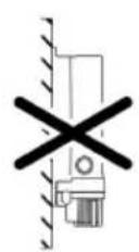
VTC0006


VTC0007
Vitronic 18 W, 24 W, 36 W
Vitronic 18 W, 24 W, 36 W

HU
VTC0011
Üzembe helyezés
Vitronic 18 W, 24 W, 36 W, 55 W

VTC0010
Vitronic 18 W, 24 W, 36 W, 55 W
natural_image
Technical line drawing of a mechanical device with no visible text or symbolsVitronic 18 W, 24 W, 36 W, 55 W

natural_image
Mechanical assembly diagram showing a hand operating a tool with a magnified inset highlighting the component (no text or symbols present)VTC0002
Vitronic 18 W, 24 W, 36 W, 55 W

VTC0005
HU
VTC0008
Tárolás/Telelés
Vitronic 11 W 18 W, 24 W, 36 W, 55 W
Vitronic 18 W, 24 W, 36 W, 55 W


VTC000€
Podłączenie


PL

VTC0007
Vitronic 18 W, 24 W, 36 W
Vitronic 18 W, 24 W, 36 W

VTC0011
Rozruch
Vitronic 18 W, 24 W, 36 W, 55 W

VTC0010
PL
Vitronic 18 W, 24 W, 36 W, 55 W
natural_image
Technical line drawing of a mechanical device with no visible text or symbolsVitronic 18 W, 24 W, 36 W, 55 W

natural_image
Mechanical assembly diagram showing a hand operating a component with a magnified inset highlighting the mechanism (no text or symbols present)VTC0003
Vitronic 18 W, 24 W, 36 W, 55 W

VTC0005
Vitronic 11 W 18 W, 24 W, 36 W, 55 W
Vitronic 18 W, 24 W, 36 W, 55 W


VTC000€
Vytvoření připojení


VTC0007
Vitronic 18 W, 24 W, 36 W
Vitronic 18 W, 24 W, 36 W, 55 W

VTC0010
Čištění a údržba
UPOZORNĚNÍ
Vitronic 18 W, 24 W, 36 W, 55 W
natural_image
Technical line drawing of a mechanical device with no visible text or symbolsVitronic 18 W, 24 W, 36 W, 55 W

natural_image
Mechanical assembly diagram showing a hand operating a tool with a magnified inset highlighting the component (no text or symbols present)VTC0003
Vitronic 18 W, 24 W, 36 W, 55 W

VTC0005
VTC0008
Uložení/zazimování
Vitronic 11 W 18 W, 24 W, 36 W, 55 W
Vitronic 18 W, 24 W, 36 W, 55 W


VTC000€


VTC0007
Vitronic 18 W, 24 W, 36 W
Vitronic 18 W, 24 W, 36 W

VTC0011
Vitronic 18 W, 24 W, 36 W, 55 W

VTC0010
Čistenie a údržba
UPOZORNENIE
Vitronic 18 W, 24 W, 36 W, 55 W
natural_image
Technical line drawing of a mechanical device with no visible text or symbolsVitronic 18 W, 24 W, 36 W, 55 W

natural_image
Mechanical assembly diagram showing a hand operating a tool with a magnified inset highlighting the component (no text or symbols present)VTC0003
Vitronic 18 W, 24 W, 36 W, 55 W
VTC0005
VTC0008
Uloženie/prezimovanie
Vitronic 18 W, 24 W, 36 W, 55 W


natural_image
Two technical diagrams showing a vehicle under checkmark and a cross symbol (no text or labels)
natural_image
Simple line drawing of a checkmark and a vertical wall-mounted device (no text or symbols)
VTC000€

VTC0007
Priključitev naprave na pretočni filter
Vitronic 18 W, 24 W, 36 W
Vitronic 18 W, 24 W, 36 W, 55 W

VTC0010
Vitronic 18 W, 24 W, 36 W, 55 W
natural_image
Technical line drawing of a mechanical device with no visible text or symbolsVitronic 18 W, 24 W, 36 W, 55 W

natural_image
Mechanical assembly diagram showing a hand operating a component with a magnified inset highlighting the mechanism (no text or symbols present)VTC0003
Vitronic 18 W, 24 W, 36 W, 55 W
VTC0005
VTC0008
Vitronic 11 W 18 W, 24 W, 36 W, 55 W
| Opis | Količina | Količina | |
| 1 | Glava uređaja | 1 | 1 |
| 2 | Kućište | 1 | 1 |
| 3 | Prozirni segmentni priključak za crijevo s O-prstenomZa crijevnu obujmicu 19 ... 38 mm | 2 | - |
| 4 | Prozirni segmentni priključak za crijevo s prebačajnom maticom i-plosnatom brtvomZa crijevnu obujmicu 25 ... 38 mm | 2 | |
| 5 | UVC svjetiljkaVitronic 11 W: tvornički prethodno montirano | - | 1 |
| 6 | Crijevna obujmica 20 - 32 mm | - | 2 |
| 7 | Crijevna obujmica 35 - 50 mm | - | 2 |
Svojstva
UV zračenje UVC uređaja za pročišćavanje uklanja plutajuće alge, bakterije i klice. UVC uređaj za pročišćavanje ugrađuje se u krug vode, idealno ispred filtra jezerca.
Simboli na uređaju
IP 24
Vitronic 18 W, 24 W, 36 W, 55 W
- Prije nego što možete pričvrstiti podlogu ne morate demontirati glavu uređaja. (→Demontiranje glave uređaja)


VTC000€


VTC0007
Vitronic 18 W, 24 W, 36 W
Uređaj je namijenjen priključivanju na protočni filtar. Oba izlazna nastavka vijčano se spajaju s ulaznim mlaznicama na protočni filtar. Pogledajte upute za upotrebu protočnog filtra.
Vitronic 18 W, 24 W, 36 W

VTC0011
Stavljanje u pogon
Vitronic 18 W, 24 W, 36 W, 55 W

VTC0010
Vitronic 18 W, 24 W, 36 W, 55 W
natural_image
Technical line drawing of a mechanical device with no visible text or symbolsVitronic 18 W, 24 W, 36 W, 55 W

natural_image
Mechanical assembly diagram showing a lever mechanism with a hand adjusting a component, no text or symbols present.VTC0003
Montiranje glave uređaja
Vitronic 18 W, 24 W, 36 W, 55 W
VTC0005
VTC0008
Vitronic 11 W 18 W, 24 W, 36 W, 55 W
Vitronic 18 W, 24 W, 36 W, 55 W


natural_image
Simple line drawing of a checkmark and a vertical wall-mounted device (no text or symbols)
VTC000€


VTC0007
Vitronic 18 W, 24 W, 36 W
Vitronic 18 W, 24 W, 36 W, 55 W

VTC0010
Vitronic 18 W, 24 W, 36 W, 55 W
natural_image
Technical line drawing of a mechanical device with no visible text or symbolsVitronic 18 W, 24 W, 36 W, 55 W

natural_image
Mechanical assembly diagram showing a hand operating a tool with a magnified inset highlighting the component (no text or symbols present)Vitronic 18 W, 24 W, 36 W, 55 W

VTC0008
Vitronic 11 W 18 W, 24 W, 36 W, 55 W
Vitronic 18 W, 24 W, 36 W, 55 W


natural_image
Simple line drawing of a checkmark and a vertical wall-mounted device (no text or symbols)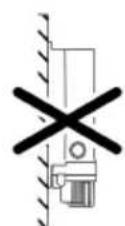
VTC0006
Свързване

Vitronic 18 W, 24 W, 36 W
Vitronic 55 W

VTC0007
Vitronic 18 W, 24 W, 36 W
Vitronic 18 W, 24 W, 36 W

VTC0011
Vitronic 18 W, 24 W, 36 W, 55 W

VTC0010
Vitronic 18 W, 24 W, 36 W, 55 W
natural_image
Technical line drawing of a mechanical device with no visible text or symbolsVitronic 18 W, 24 W, 36 W, 55 W

natural_image
Mechanical assembly diagram showing a hand operating a tool with a magnified inset highlighting the component (no text or symbols present)VTC0003
Vitronic 18 W, 24 W, 36 W, 55 W

VTC0005
VTC0008
Vitronic 11 W 18 W, 24 W, 36 W, 55 W
Vitronic 18 W, 24 W, 36 W, 55 W
Vitronic 18 W, 24 W, 36 W


VTC0006


VTC0007
UK
Vitronic 18 W, 24 W, 36 W
Vitronic 18 W, 24 W, 36 W

VTC0011
Vitronic 18 W, 24 W, 36 W, 55 W

VTC0010
Чистка і догляд
ПРИМІТКА
Vitronic 18 W, 24 W, 36 W, 55 W
natural_image
Technical line drawing of a mechanical device with no visible text or symbolsVitronic 18 W, 24 W, 36 W, 55 W

natural_image
Mechanical assembly diagram showing a hand operating a tool with a magnified inset highlighting the component (no text or symbols present)VTC0003
Vitronic 18 W, 24 W, 36 W, 55 W

VTC0005
VTC0008
Vitronic 11 W 18 W, 24 W, 36 W, 55 W
Vitronic 18 W, 24 W, 36 W, 55 W
Vitronic 18 W, 24 W, 36 W


natural_image
Two technical diagrams showing a vehicle under checkmark and a truck with cross symbol (no text or labels)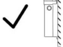
VTC0006

VTC0007
RU
Vitronic 18 W, 24 W, 36 W
Vitronic 18 W, 24 W, 36 W

VTC0011
Пуск в эксплуатацию
Vitronic 18 W, 24 W, 36 W, 55 W

VTC0010
Очистка и уход
УКАЗАНИЕ
Vitronic 18 W, 24 W, 36 W, 55 W
natural_image
Technical line drawing of a mechanical device with no visible text or symbolsVitronic 18 W, 24 W, 36 W, 55 W
natural_image
Mechanical assembly diagram showing a hand operating a tool with a magnified inset highlighting the component (no text or symbols present)VTC0003
Vitronic 18 W, 24 W, 36 W, 55 W

VTC0005
VTC0008
Vitronic 18 W, 24 W, 36 W, 55 W


natural_image
Two technical diagrams showing a vehicle under checkmark and a truck with cross symbol (no text or labels)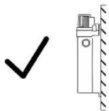
natural_image
Simple line drawing of a checkmark and a vertical wall-mounted device (no text or symbols)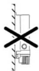
VTC000€
建立连接

VTC0007
CN
连接设备与贯通式过滤器。
Vitronic 18 W, 24 W, 36 W
Vitronic 18 W, 24 W, 36 W, 55 W
VTC0010
清洁和保养
提示
Vitronic 18 W, 24 W, 36 W, 55 W
步骤如下:
natural_image
Technical line drawing of a mechanical device with no visible text or symbolsVitronic 18 W, 24 W, 36 W, 55 W

natural_image
Mechanical assembly diagram showing a hand operating a tool with a magnified inset highlighting the component (no text or symbols present)VTC0001
安装设备头
步骤如下:
Vitronic 18 W, 24 W, 36 W, 55 W

VTC0005
清洁石英玻璃/更换 UVC 紫外线灯
VTC0008
存放/过冬
- Vitronic
- Vitronic 18 W, 24 W, 36 W, 55 W
- Vitronic 18 W, 24 W, 36 W
- Inbetriebnahme
- Gerätekopf einbauen
- Lagern/Überwintern
- Safety information
- Electrical connection
- Safe operation
- Intended use
- Product description
- Scope of delivery
- Properties
- Installation and connection
- Vitronic 11 W
- Installing the unit
- Establishing the connections
- Connecting the unit to the flow-through filter.
- Commissioning/start-up
- Switching ON/OFF
- Maintenance and cleaning
- NOTE
- Dismantling the unit head
- CAUTION
- Fitting the unit head
- Cleaning the quartz glass / Replacing the UVC lamp
- Prerequisite
- Storage/overwintering
- Wear parts
- Disposal
- AVERTISSEMENT
- Ingebruikname
- Apparaatkop monteren
- Opslag/overwinteren
- Montar a cabeça
- Armazenar/Invernar
- Messa in funzione
- Skab forbindelse
- Montering af apparathoved
- Sådan gør du:
- Opbevaring/overvintring
- Igangsetting
- Lagring/overvintring
- Driftstart
- Montera apparatens ovandel
- Gör så här:
- Käyttöönotto
- Puhdistus ja huolto
- OHJE
- Laitepään asennus
- Üzembe helyezés
- Tárolás/Telelés
- Podłączenie
- Rozruch
- Vytvoření připojení
- Čištění a údržba
- UPOZORNĚNÍ
- Uložení/zazimování
- Čistenie a údržba
- UPOZORNENIE
- Uloženie/prezimovanie
- Priključitev naprave na pretočni filter
- Svojstva
- Simboli na uređaju
- IP 24
- Stavljanje u pogon
- Montiranje glave uređaja
- Свързване
- Чистка і догляд
- ПРИМІТКА
- Пуск в эксплуатацию
- Очистка и уход
- УКАЗАНИЕ
- 建立连接
- 连接设备与贯通式过滤器。
- 清洁和保养
- 提示
- 安装设备头
- 清洁石英玻璃/更换 UVC 紫外线灯
- 存放/过冬
Brand : OASE
Model : Vitronic 18 W
Category : Water filter