PU-30 - Projector MSW - Free user manual and instructions
Find the device manual for free PU-30 MSW in PDF.

| Product Type | Mortar Spraying Machine |
| Brand | MSW |
| Model | PU-30 |
| Rated Voltage | 230 V ~ 50 Hz |
| Rated Power | 2800 W |
| Working Pressure | 30 bar (435 psi) |
| Motor Protection | Yes (overheating) |
| Insulation Class | F |
| Motor Speed | 0 - 2500 rpm |
| Spiral Speed | 0 - 160 rpm |
| Protection Rating | IP54 |
| Duty Cycle | S1 |
| Flow Rate | 18 l/min |
| Max. Grain Size | 3 mm |
| Required Air Pressure | 10 bar |
| Hopper Capacity | 40 l |
| Dimensions (L x W x H) | 102 x 49 x 63 cm |
| Weight | 60.7 kg |
| Processable Materials | Mineral plasters, plasters, artificial resins (up to 3 mm) |
| Usage | Professional commercial |
| Electrical Safety | Residual current device <= 30 mA recommended |
| Cleaning | Do not use high pressure cleaner on the motor |
| Wear Parts | Rotor and stator replaceable |
| Regular Maintenance | Check mortar hose, lubricate pump |
Frequently Asked Questions - PU-30 MSW
User questions about PU-30 MSW
0 question about this device. Answer the ones you know or ask your own.
Ask a new question about this device
Download the instructions for your Projector in PDF format for free! Find your manual PU-30 - MSW and take your electronic device back in hand. On this page are published all the documents necessary for the use of your device. PU-30 by MSW.
USER MANUAL PU-30 MSW
natural_image
Technical line drawing of a pressure vessel with internal components and wheels (no text or symbols)Sprühlanze
Befestigung
WARTUNG

This User Manual has been translated for your convenience using machine translation. Reasonable efforts have been made to provide an accurate translation; however, no automated translation is perfect nor is it intended to replace human translators. The official User Manual is the English version. Any discrepancies or differences created in the translation are not binding and have no legal effect for compliance or enforcement purposes. If any questions arise related to the accuracy of the information contained in the User Manual, please refer to the English version of those contents which is the official version.
TECHNICAL DATA
| Parameter description | Parameter value | |
| Product name | Plastering Machine | |
| Model | MSW-PU-20 | MSW-PU-30 |
| Rated voltage [V~] / frequency [Hz] | 230 / 50 | 230 / 50 |
| Rated power [W] | 2200 | 2800 |
| Working pressure [bar] | 20 | 30 |
| Maximum working pressure [psi] | 290 | 435 |
| Motor overheat protection | yes | yes |
| Insulation class | F | F |
| Rotation speed [rpm] | Motor: 0 - 2500; Spiral: 0 - 160 | Motor: 0 - 2500; Spiral: 0 - 160 |
| IEC protection class | I | I |
| Protecting grade | IP54 | IP54 |
| Duty cycle of a device | S1 | S1 |
| Flow rate [l/min] | 15 | 18 |
| Maximum grain size [mm] | 3 | 3 |
| Air pressure [bar] | 10 | 10 |
| Maximum capacity [l] | 40 | 40 |
| Dimensions (width x depth x height) [mm] | 96 x 53 x 88 102 x 49 x 63 | |
| Weight [kg] | 50 | 60.7 |
Please read and keep this manual, Read carefully before attempting to assemble, install, operate or maintain the product described. Protect yourself and others by observing all safety information.
Failure to comply with instructions could result in personal injury and/or property damage! Retain instruction for future reference.
Warning!
Mortar spraying machines develop high spraying pressures.

Attention – Danger of injury!
1) Never reach into the spray jet with your fingers or hand!
Never point the spray lance at yourself or other persons! Coating materials are caustic or irritating!
Protect your skin and eyes!
2) The following points are to be observed in accordance with the operating manual before every start-up:
a. Observe the permissible pressures.
b. Check all the connecting parts for leaks.
3) Instructions for regular cleaning and maintenance of the machine are to be observed strictly. Observe the following point before any work on the machine and at every working break:
a. Observe the curing time of the coating material.
b. Depressurize the spray lance and mortar hose.
c. Switch off the suction pump.
SAFETY REGULATIONS
The following sources are just a sample of those containing safety requirements for mortar conveyors:
a) EN 12001:2003, Conveying, spraying and placing machines for concrete and mortar - Safety requirements.
All local safety regulations in force must be observed.
The following specifications are to be observed in particular to handle mortar spraying machines safely:
Usage of the mortar spraying machine
The mortar spraying machine may only be used to process the coating materials described.
Any other usage is not allowed.
Proper usage also includes the observance of the operating manual and the observance of the inspection and maintenance conditions. Always keep the operating manual on hand at the point of use of the mortar spraying machine.
Use only marked mortar hoses with at least 40 bars operating- pressure.
The mortar spraying machine is intended exclusively for commercial use by professionals.
Protection of persons
In order to protect eyes, skin and the respiratory organs: Wear safety goggles, protective clothing, gloves, possibly use protective skin cream and respiratory equipment. Do not decouple the mortar hose as long as it is under pressure. Watch the manometer! Wear safety goggles! Do not point the spray lance at persons!
In order to protect your ears wear ear protection.
Wear safety shoes when transporting the machine or working with it.
People not needed to assist with machine installation, assembly or operation, must keep away from the machine.
Breathing masks
Make a breathing mask available to the processor in order to protect against mineral dust.
Connection to the mains network only via a special feeding point, for example via a distribution board for construction sites, with residual current protective device with INF ≤ 30 mA.
Avoid soiling of the socket for the remote control at the control unit.

Risk of injury from escaping material. Before switching on, always check that the material tap on the spray lance is closed. Close material tap whenever stopping work.

Never operate the mortar spraying machine if the rotor is exposed or if the container has been removed.
Do not reach into the rotor when it is moving. Risk of crushing.
Caution if you have long hair. Only wear close-fitting clothes at work.
Do not insert objects or body parts through the protective grid.
Risk of crushing when folding in the handles, assembling the pump unit and connecting the mortar hose.
Cleaning and maintenance
Never decouple mortar hose or disassemble machine when under pressure. Note pressure reading on pressure gauge.
When performing maintenance work, always switch off mor- tar spraying machine, disconnect mains plug and ensure it cannot be plugged back in by mistake.
Do not spray down the motor and control unit of the mortar spraying machine with a water-jet, high-pressure cleaner or high-pressure steam cleaner. Danger of short-circuits caused by water ingress.
Electrical equipment
Work on the machine's electrical equipment may be carried out only by a qualified electrician. The electrical equipment is to be checked regularly. Eliminate faults such as loose connections or scorched cables.
Keep the label on the mortar spraying machine clean and legible.

Danger of injury through leaking high- pressure hose. Wear and tear and links as well as usage that is not appropriate to the purpose of the device can cause leakages to form in the mortar hose. Liquid can be injected into the skin through a leakage.
Mortar hose
- Mortar hoses must be checked thoroughly before they are used.
- Replace any damaged mortar hose immediately. Never repair defective mortar hoses yourself!
- Avoid sharp bends and folds: the smallest bending radius is about 80 cm.
- Do not drive over the mortar hose. Protect against sharp objects and edges.
- Never pull on the mortar hose to move the device. Do not twist the mortar hose.
- Lay the mortar hose in such a way as to ensure that it cannot be tripped over.

Only use original-mortar hoses in order to ensure functionality, safety and durability.

The risk of damage rises with the age of the mortar hose.
DP recommends replacing mortar hoses after 6 years.
WORKING WITH THE MORTAR SPRAYING MACHINE
The suction pump is conceived for using and processing ready mixed mineral coating materials.
The machine is not designed for use as a cleaning device.
Function of the mortar spraying machine
The coating material is supplied by means of the container. The spiral conveyor feeds the coating material to the eccentric screw pump. The suction effect causes the coating material to enter the eccentric screw pump. This pump builds up the pressure required for transportation through the mortar hose. The compressed air required for atomization is supplied at the spray lance. The mortar spraying machine can be switched on and off using the electric control. This can also be used to control the delivery volume.
A soft even spray pattern can be achieved by means of the smoothly regulated convey capacity of the coating material.
Processible coating materials
• Thermal insulation composite system bonding agent (mineral and artificial resin systems)
• Artificial resin plasters up to 3 mm granular size
- Silicate plasters up to 3 mm granular size
- Silicone resin plasters up to 3 mm granular size
• Mineral final coats up to 3 mm granular size
• Lightweight plaster systems up to 3 mm granular size
- Scraped stucco up to 3 mm granular size
• Thermal insulation plasters
- Restoration plaster
- Porous concrete coating
- Quartz plastic
- Roof coatings
- Fire protection coatings
• Mineral sealing sludges
- Bitumen emulsions
- Armoring filler
• Liquid wood-chip wall paper
- casement grouting mortar
• Artificial resin rendering base
- Wash primer
- Filling paint, also fibrous
- Elastic coating
• Acoustic plaster, artificial resin bonded
- Fillers, artificial resin bonded
All the coating materials must be suitable for machine processing. Refer to the product data sheet of the coating material to be processed.
Use other coating materials only after agreement with the manufacturer or the application technology service.
EXPLANATORY DIAGRAM
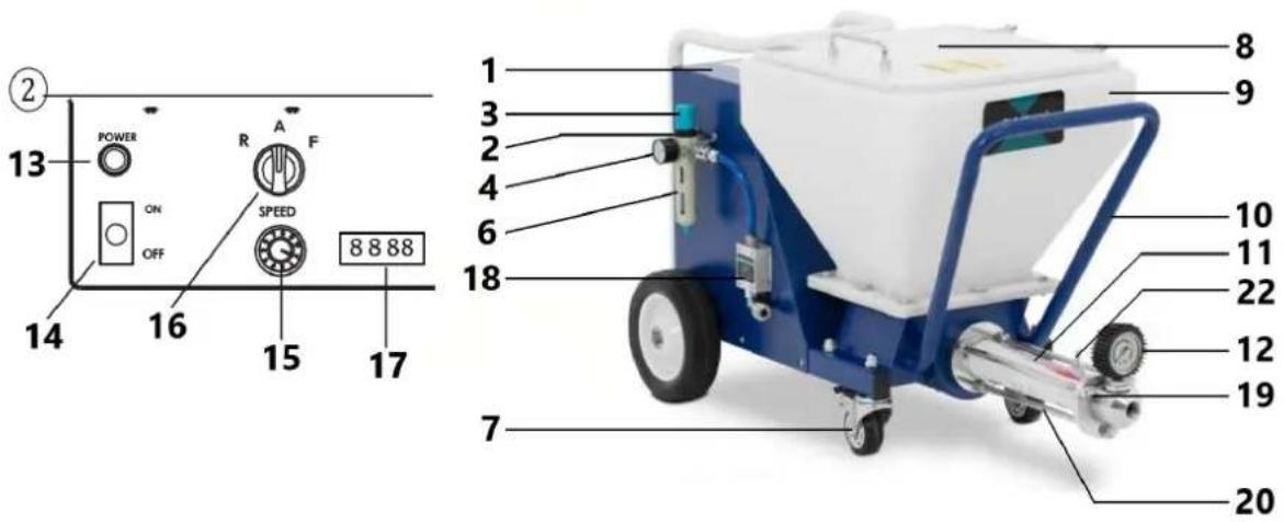
| Item | Description | Item | Description |
| 1 | Control board | 13 | Power Indicator light |
| 2 | Air inlet | 14 | ON/OFF switch |
| 3 | Air pressure regulator | 15 | Speed switch |
| 4 | Air gauge | 16 | Manual/Automatic switch |
| 5 | Motor | 17 | Speed display |
| 6 | Oil-water separator | 18 | Pneumatic sensor |
| 7 | Universal wheel | 19 | Discharge valve body |
| 8 | Dust cover | 20 | Fixing screw |
| 9 | Receptacle | 21 | Power cable |
| 10 | Frame | 22 | Grounding wire clip |
| 11 | Screw pump body | 23 | Drain valve |
| 12 | Pressure gauge | 24 | Gearbox |
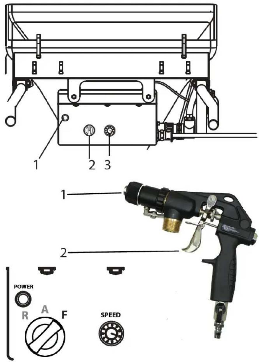
Operating elements and displays on device
1 - Operating light (Power)
2 - Power switch
3 - Selector switch for operating mode
4 - Delivery volume controller
5 - Speed display
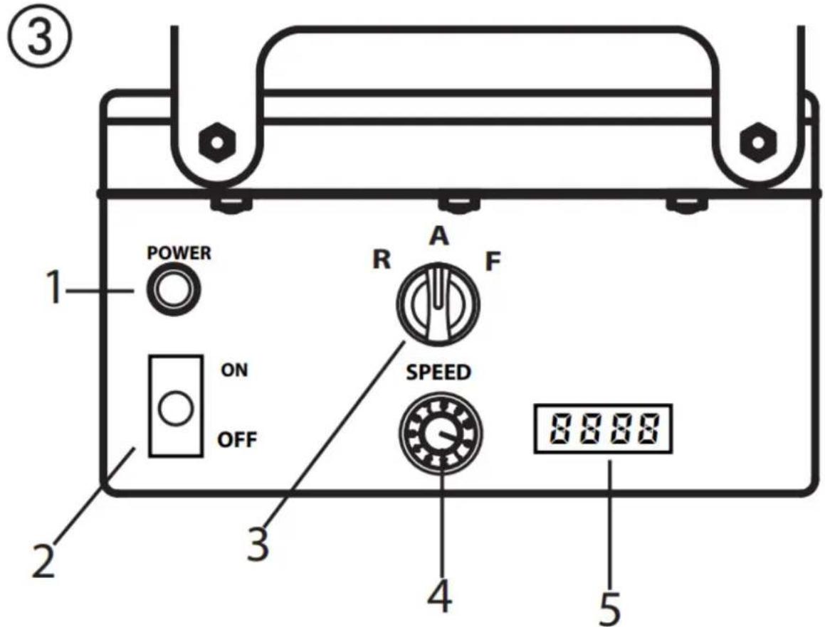
The delivery volume controller (Fig. 3, 1) is used to regulate the convey capacity from 0-10 smoothly.
The selector switch offers the following modes:
 | “AUTO” position = automaticBasic setting for control with an automatic spray lance |
 | “F” position = manual activationSwitches on the mortar spraying machine.This setting is required for:disassembling the pump unitWhen using the pneumatic lance, this set- ting is also needed for:pre-rinsing the mortar hose to improve the material’s ability to slidecleaning |
 | “R” position = reverse gearThis setting is required for:releving pressure on the mortar hoseassembling the pump unit |
Detailed explanation of selector switch use:
If the selector switch is in the "A" position and can be switched on and off with the material shut-off on the automatic spray lance.
If there is no spray lance fitted (e.g.: assembly/disassembly the pump unit), the machine is switched on using the "F" switch position and off using the "A" position.
Since the air supply through the compressor needs to be switched off to clean the mortar hose, the pneumatic lance is not controlled using the material shut-off. In this case, the machine must therefore also be switched on using the "F" position.

Important: control via the selector switch and material shut-off are treated equally.
The machine can be switched from the “A” position (control using material shut-off) to “F” at any time.
We would therefore recommend that only one person operate the machine.
The operating light (RED) indicates that the machine is energized and ready.

The drive unit heats up during operation. This is normal and not a sign of malfunction.
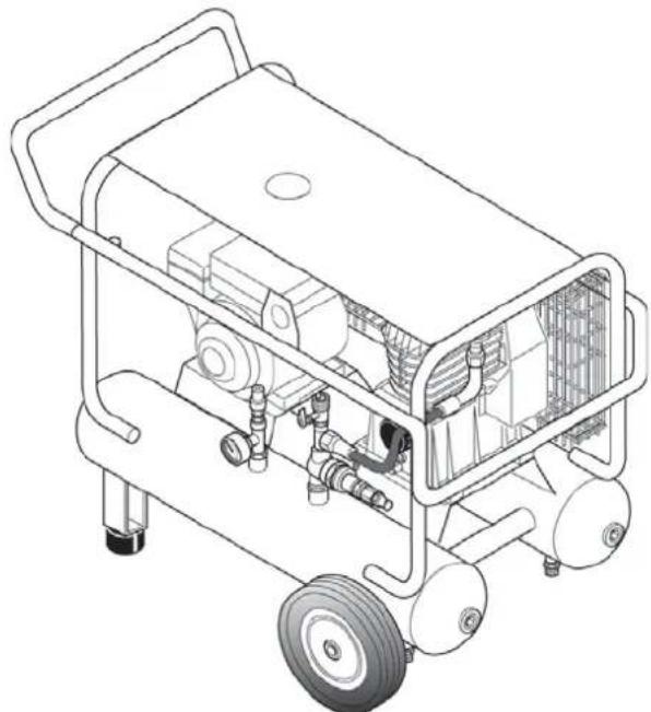
Compressor (accessory)
intake volume 590 l/min
Note: Only operate the compressor in accordance with the enclosed operating manual.
natural_image
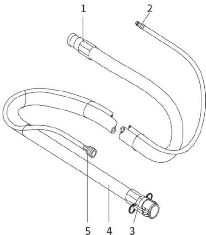
Technical line drawing of a pressure pump cart with visible internal components and wheels (no text or labels)Mortar hose for pneumatic spray lance
1 - Material connection mortar spraying machine
2 - Atomizing air connection compressed air supply
3 - Material connection spray lance
4 - Mortar hose
5 - Atomizing air connection spray lance
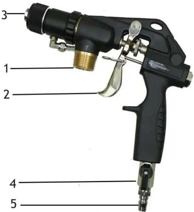
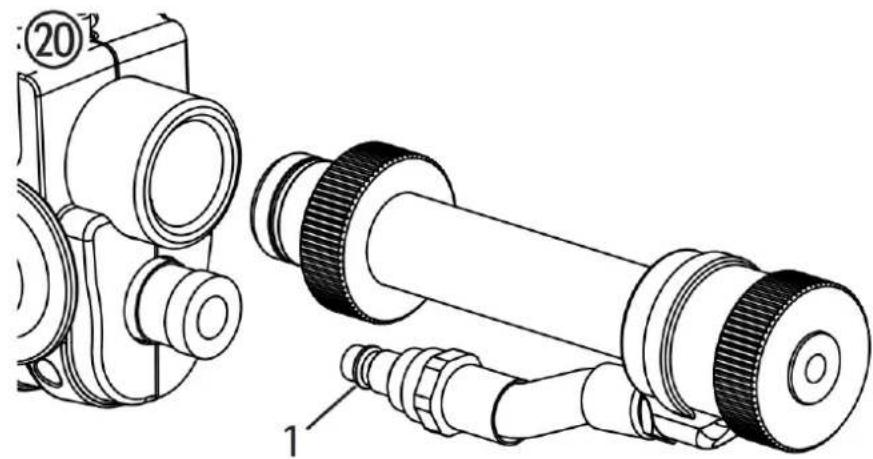
Spray lance
1 - Material connection (quick coupling not shown)
2 - Combined material and air tap:
3 - Texture tip:
Various texture tips can be used in the spray lance. The tip size depends on the granular size of the coating material and the desired spray pattern.
4 - Air flow regulator
5 - Atomization air connection
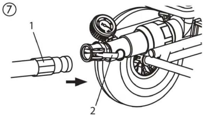
• Check that the pump unit is seated firmly.
- Connect mortar hose (Fig. 7, 1) and secure with clamping levers (Fig. 7, 2).
- Connect atomizing air connection on mortar hose to front connection on handle and compressor air hose (accessory) to connection on oil-water separator
EN
- Select a spray tip suitable for the material: The tip size should amount to at least three times the granular size, e.g. granular size artificial resin plasters -> 3 mm Tip size -> 10 mm
Preparing the mortar spraying machine
Recommended sliding means for the mortar hose
Water is not sufficient as a sliding means. Danger of clogging!
Use cellulose paste (e.g. metylan wallpaper paste)
- Fill 2–3 | cellulose paste into the container.
- connect the mortar spraying machine to the mains supply.
• The operation light (1) shows operational readiness.
Risk of injury from escaping material. Before switching on, always check that the material tap on the spray lance is closed Close material tap whenever stopping work.
Rinse the mortar hose (pneumatic spray lance)
- Switch off compressor.
Do not bend the mortar hose! Protect it against damage, for example against being driven over as well as against sharp objects and edges.
- Hold spray lance over an empty bucket.
- Set selector switch to "F".
- Open material tap on spray lance.
• If cellulose paste comes out of the tip, close the material tap - Set selector switch to "A".
• Fill coating material into the receptacle.
With mineral coating materials only fill the receptacle to half full.
• Position the spray lance over the bucket again.
- Set selector switch to "F".
- Open material tap on spray lance.
• As soon as coating material exits from spray lance, close material tap
- Set selector switch to "A".
- Switch on compressor.
• The mortar spraying machine is now full and ready.
Beginning of the spraying process
- Open the air flow regulator and the material tap at the spray lance.
- Adjust the flow of material with the delivery volume con-troller on the control unit and set the air quantity by adjusting the air flow regulator to attain the desired spray pattern.

Important: Do not let the mortar spraying machine run dry. Switch the device off immediately if no more material comes out of the tip or if the spray line becomes irregular. Possible reasons for the problem and how to correct it can be found in the chapter called „Eliminating faults“.

Increased material tap wear. Do not use the material tap to set the material volume. The delivery volume controller should be used for this purpose.
End of the spraying process
- close the material tap
- close the air flow regulator

Always close material tap at end of the spray process.
APPLICATION TECHNIQUE
Spraying technique
While spraying hold the spray lance at a uniform distance of 30 – 60 cm from the object. Otherwise the spray pattern will be uneven.
The spray pattern depends on the coating material, viscosity, tip size, convey capacity and amount of atomizing air.
Examples:
Fine texture -> large amount of atomizing air
Rough texture -> small amount of atomizing air
Higher convey capacity -> larger amount of atomizing air
Test the desired texture on a test surface.
The lateral limit of the spray jet should not be too sharp. The distance between the spray lance and the object should therefore be selected correspondingly.
The spray edge should be gradual in order to facilitate over-lapping of the next coat.
If the spray lance is moved parallel and at an angle of 90^ to the surface to be coated, the paint mist is minimized.
Note:
Grains and pigments with a sharp edge result in a high rate of wear of the pump, mortar hose, material tap and tip.

When using the mortar hose while working on scaffolding, it is best to always guide the hose along the outside of the scaffolding.
SHUTTING DOWN AND CLEANING

Do not clean the motor and control unit of the mortar spraying machine moistly. And certainly do not spray down the unit with high-pressure cleaners or high-pressure steam cleaners. Danger of short-circuits caused by water ingress.
Cleaning the mortar hose
• Pump until receptacle is empty.

Important: Do not let the mortar spraying machine run dry. Switch the device off immediately if no more material comes out of the tip or if the spray line becomes irregular. Possible reasons for the problem and how to correct it can be found in the chapter called „Eliminating faults“.
- Switch off mortar spraying machine and compressor.
• close material tap on spray lance. - Remove the texture tip from the spray lance and clean it.
- Put water in the container and hold the spray lance over an empty bucket.
Important: Do not let the mortar spraying machine run dry. During the cleaning process, ensure that there is al- ways enough water in the container.
- Set delivery volume controller to „5“.
• Using pneumatic lance, set selector switch to "A".

The mortar hose must NOT be under pressure. If necessary, set the selector switch briefly to "R" (reverse). Watch the manometer —> 0 bar. Wear safety goggles.
• Decouple mortar hose from pump unit.
• Decouple spray lance from mortar hose.
- Insert cleaning ball into mortar hose and reconnect mortar hose
- Set selector switch to "F".
• After a few seconds the cleaning ball is emitted from the spray lance.
- Depending on the processed coating material, repeat the cleaning process 3 – 4 times.

The mortar hose must NOT be under pressure. If necessary, set the selector switch briefly to "R" (reverse). Watch the manometer —> 0 bar. Wear safety goggles.
- Set selector switch to "A".
• Decouple mortar hose from pump unit.
Cleaning the device and replacing the stator
- Clean mortar spraying machine. To do so, pump graphite pump sliding means or water mixed with dishwashing liquid through the pump
Dismantling

Mortar spraying machine must be depressurized. If necessary, set the selector switch briefly to "R" (reverse). Watch the manometer —> 0 bar. Wear safety goggles.

Disconnect the remote control and external controls. Only the person operating the machine may remove the pump unit.
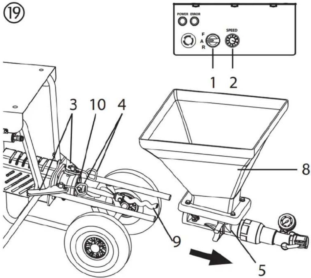
- Move selector switch (1) to "A" and set delivery volume con-troller (2) to „0“.
- Loosen the union nut on the pump tube using the special wrench (approx. a one-quarter turn)
- Push the clamping lever (3) forwards to release the lock.
- Unhook the hooks (4) and fold them away to the side.
- Set delivery volume controller (2) to 1 or 2.
- Hold the container with one hand. Move the selector switch to position "F". As soon as the pump unit (5) has released, move selector switch to "A" and remove pump unit.
-
Disconnect mains plug.
-
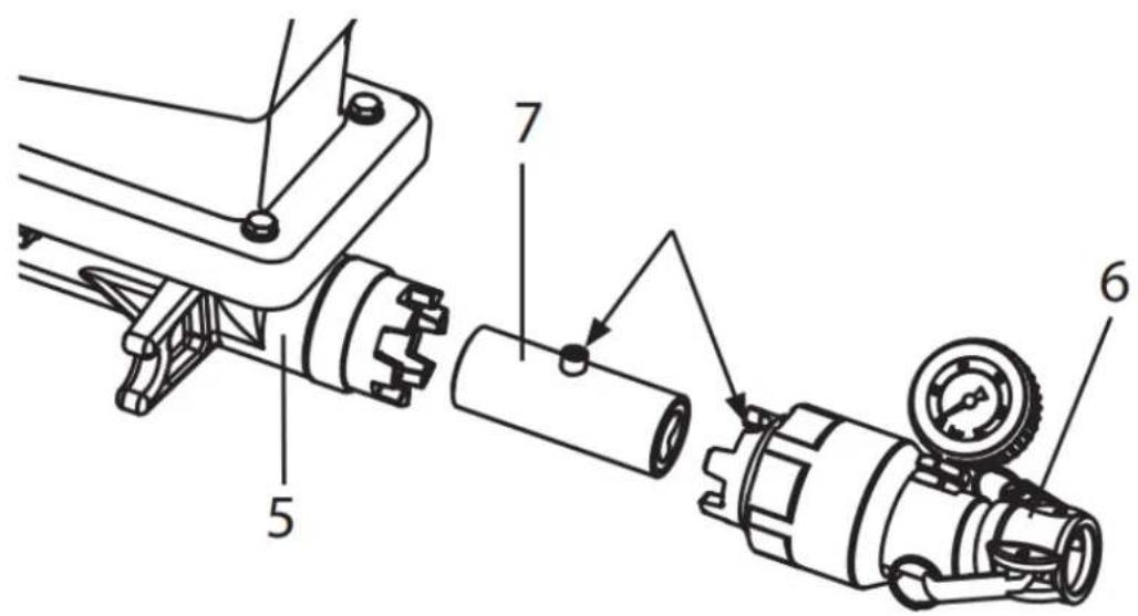
Loosen/unscrew pump pipe (6) from pump unit (5) using the special key provided.
- Remove stator (7) from pump pipe.
Cleaning the pump unit
- Clean the pump unit (5) with a jet of water and a suitable bottle brush.
- Clean the container (8) with a jet of water and a suitable brush.
- Clean the protective grid with a radiator brush.
- Also clean the rotor (9), stator (7) and pump tube (6) thoroughly with water and, if necessary, using a brush.
- Clean the flat gasket (10).
- Then spray rotor (9) and stator (7) and with a suitable pump lubricant.
- Keep the thread of the pump housing and the pump tube clean so that leaking after the assembly is avoided.
Mounting
- Insert stator (7) in pump pipe (6) such that the journal sits in the largest recess.
• Use special key to screw pump pipe back onto pump unit (5).
Cleaning the spray lance
- Clean the texture tip.
- Use cleaning needles to clean the air holes in the texture tip.
• Clean and lubricate the O-ring (fig. 20, 1). - Clean the spray lance and material tube on the inside using a bottle brush (0342 329).
• Clean all threads thoroughly. - Rinse the spray lance with clear water. Open and close the material tap three times as you are doing this.
MAINTENANCE

ATTENTION! It is imperative that the machine be deenergized by unplugging the plug before all work and maintenance work. Otherwise there is a danger of short-circuiting! Repairs may only be carried out by qualified personnel who dispose the corresponding training and experience. The device must be tested by a skilled electrician after every repair.
The mortar spraying machine is designed so that a minimum of care and maintenance is required. However, the following work has to be carried out and components checked regularly:
Mechanical maintenance
- Keep the thread at the pump tube and pump housing clean and, if appropriate, seal.
- Check the seals at all the couplings and connecting pieces for leaks. If appropriate, replace worn seals.
- Check the following for damage before every usage:
○ Mortar hose
- Power cable
- Control unit
- Remote control connection cable (if present)
Electrical maintenance
The electrical drive and its ventilation slots must always be kept clean and may not be cleaned with water. Danger of short-circuits.
Long periods of non-usage
If the mortar spraying machine is not used for a longer period, it has to be cleaned thoroughly and protected against corrosion.

Remove the stator from the pump unit ensuring that it cannot become set at the rotor.
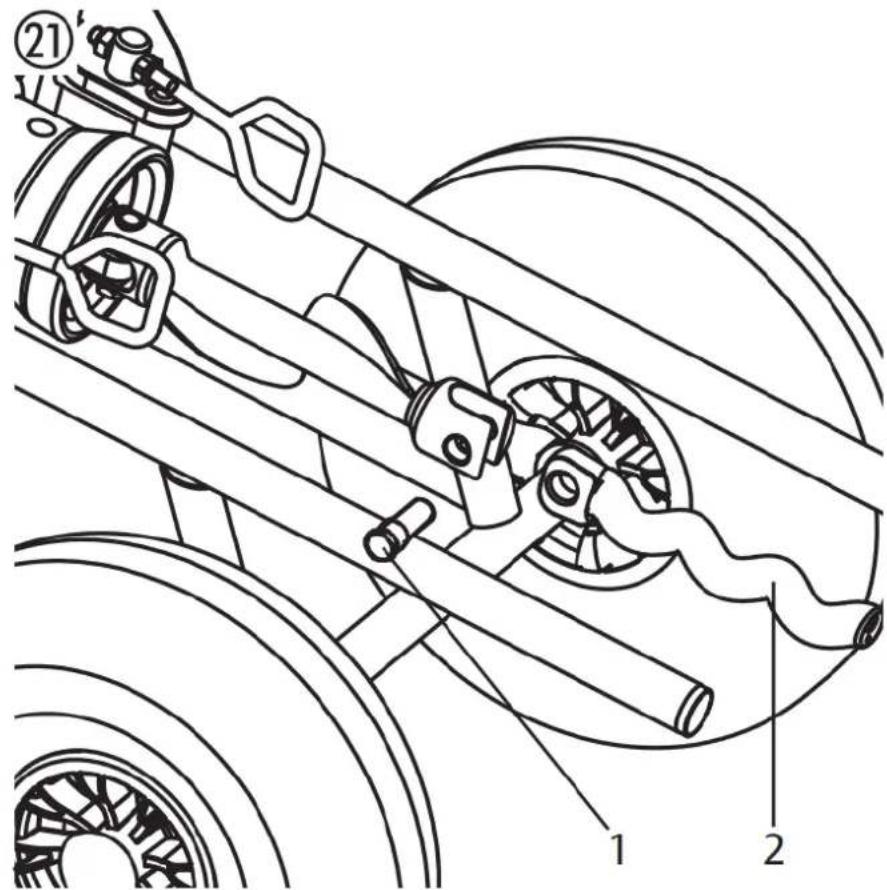
Rotor replacement (fig. 21)
- Loosen fixing screw (1) and remove old rotor (2).
• Fit new rotor with new fixing screw. - Glue fixing screw with Loctite 243.

Note: use Loctite 243 only.
ELIMINATING FAULTS
| Malfunction | Possible cause | Elimination |
| Mortar spraying machine not running. | Delivery volume controller is set to „0“Hose not connected or damaged | Increase delivery volumeCheck control hose |
| Mortar spraying machine not running. | Power supply missing. | Plug in the power plug.Check the power cable for damage and replace, if necessary.Check the power supply |
| Mortar spraying machine not running. | Mortar spraying machine was over- loaded/ overheated. | Close material tap and disconnect mains plug. Switch the mortar spraying machine on again after about 5 minutes. |
| Mortar spraying machine can- not rotate the rotor | Rotor stuck in stator.Pump was not lubricated with pump sliding means. | Set the selector switch alternatively briefly to “F” (forwards) – “R” (reverse).Contact customer service if the problem cannot be resolved. |
| Mortar spraying machine builds up pressure in the mortar hose. However, coating material does not arrive at the spray lance. | Coating material "plug" in the mortar hose. Mortar hose not prerinsed with cellulose paste. | Depressurize the mortar hose – set the selector switch to “R” (reverse).Pump the coating material back into the container. The mortar hose must NOT be under pressure. Watch the manometer → 0 bar. Wear safety goggles.Decouple mortar hose and rinse with water hose. When the plug has been removed, fill cellulose paste in the mortar hose. Couple the mortar hose back on. The mortar hose must NOT be under pressure. Watch the manometer → 0 bar. Wear safety goggles.Decouple mortar hose and rinse with water hose. When the plug has been removed, fill cellulose paste in the mortar hose. Couple the mortar hose back on. |
| Coating material is suddenly not emitted during spraying. | Texture tip is clogged because of impurity in the coating material or be-cause the granular size is too large. | Switch the mortar spraying machine off. close the material cock at the spray lance. Remove the texture tip and clean it. |
| Texture tip too small. | Select a larger texture tip. Rule of thumb: Granular size x 3 —> Tip size | |
| Coating material “plug” in the mortar hose. Mortar hose not prerinsed with cellulose paste. | Depressurize the mortar hose – set the selector switch to “R” (reverse). Pump the coating material back into the container. The mortar hose must NOT be under pressure.Watch the manometer —>0 bar. Wear safety goggles.Decouple mortar hose and rinse with water hose. When the plug has been removed, fill cellulose paste in the mortar hose. Couple the mortar hose back on. The mortar hose must NOT be under pressure.Watch the manometer —>0 bar. Wear safety goggles.Decouple mortar hose and rinse with water hose. When the plug has been removed, fill cellulose paste in the mortar hose. Couple the mortar hose back on. | |
| No coating material in the container. Pump has sucked in air. | Refill the container with coating material and pump it around until the coating material emerges without any bubbles.Attention:Always top up with sufficient coating material. Do not let the pump run dry. Pump overheats, resulting in a danger of „plugs“. | |
| Spray pattern is not clean and even. | Air ducts in the texture tip are partially closed with coating material. | Switch the mortar spraying machine off. close the material tap at the spray lance.Remove the texture tip. Clean the air ducts of the texture tip. |
| Air volume incorrectly set. | Change air volume setting. | |
| Poor mortar spraying machine cleaning | Thoroughly clean mortar spraying machine | |
| No coating material in the container. Pump has sucked in air. | Refill the container with coating material and pump it around until the coating material emerges without any bubbles.Attention:Always top up with sufficient coating material. Do not let the pump run dry. Pump overheats, resulting in a danger of „plugs“. | |
| Pressure at the manometer rises to more than 40 bars. | Viscosity of the coating material too high.Mortar hose diameter too small.Mortar hose is too long.Coating material “plug” in the mortar hose. Mortar hose not prerinsed with cellulose paste. | Dilute the coating material.Use a mortar hose with a larger diameter.Use a shorter mortar hose.Depressurize the mortar hose – set the selector switch to “R” (reverse).Pump the coating material back into the container.The mortar hose must NOT be under pressure.Watch the manometer → 0 bar. Wear safety goggles.Decouple mortar hose and rinse with water hose. When the plug has been removed, fill cellulose paste in the mortar hose. Couple the mortar hose back on. |
| Mortar spraying machine does not pump enough coating material. | convey capacity selected too low. Mortar hose diameter too small. Stator worn.Texture tip too small.convey capacity selected too low. Mortar hose diameter too small. Stator worn.Texture tip too small. | Set the volume regulator higher.Use a mortar hose with a larger diameter.Mount a new stator, if necessary, also a new rotor.Attention: Spray on pump sliding means.Select a larger texture tip.Rule of thumb:Granular size x 3 → Tip size |
Coating material is emitted at the inspection hole (1).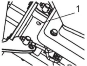 | The shaft seal that seals between the pump unit and the drive unit is worn. | Stop work immediately because otherwise coating material may enter the drive and result in a defect.Clean machine and contact customer service. |
If the defect is not caused by one of the above-mentioned faults, have the defect eliminated by the customer service.
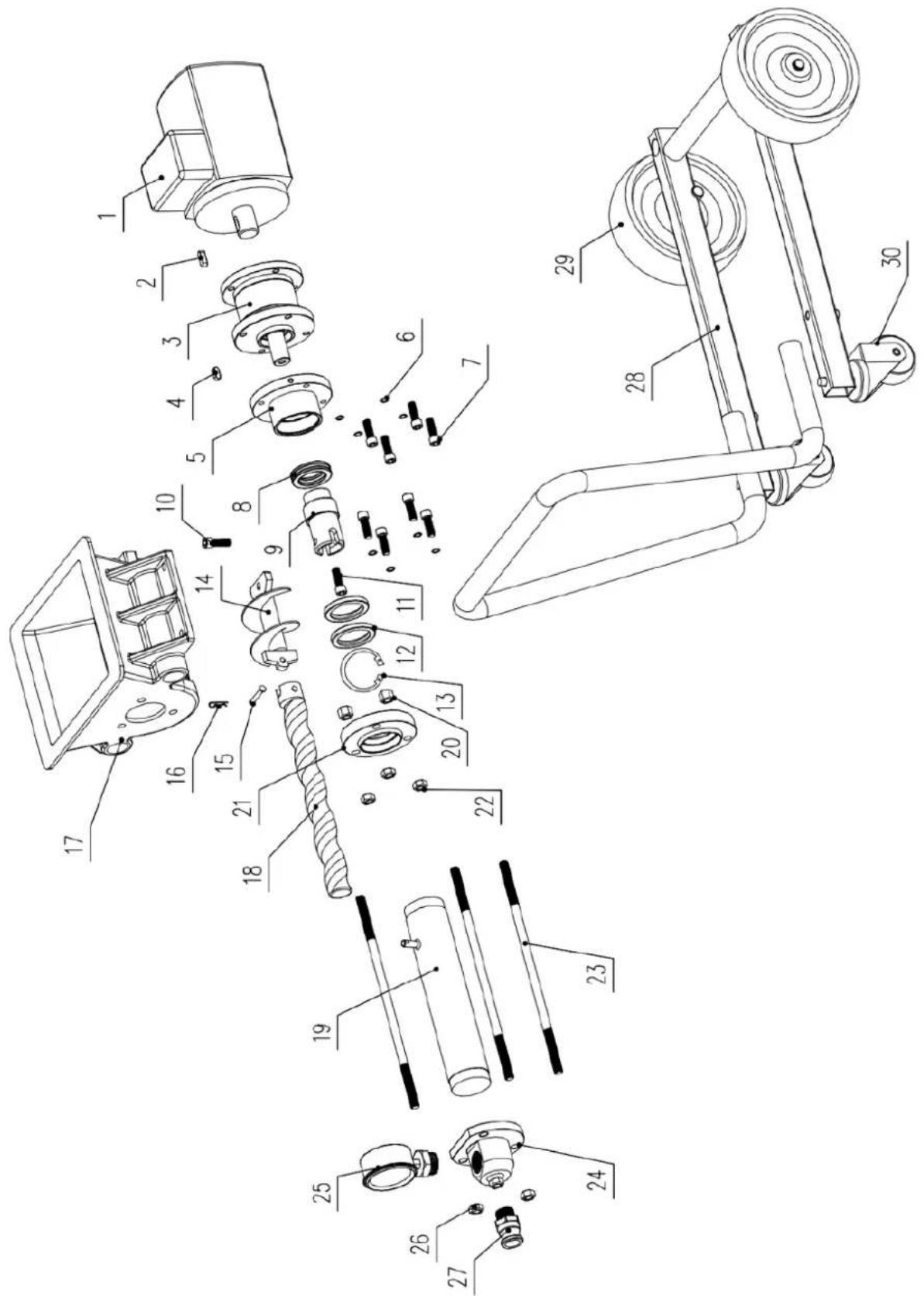
| Item | Description | Quantity | Item | Description | Quantity |
| 1 | Motor | 1 | 16 | R-shaped buckle | 1 |
| 2 | Pin | 1 | 17 | Receptacle | 1 |
| 3 | Gearbox | 1 | 18 | Rotor | 1 |
| 4 | Pin | 1 | 19 | Stator | 1 |
| 5 | Output flange | 1 | 20 | Screw | 3 |
| 6 | Spring washer | 4 | 21 | Rear Flange, stator | 1 |
| 7 | Screw | 4 | 22 | Fixing screw | 3 |
| 8 | Bearing | 1 | 23 | Long screw | 3 |
| 9 | Output shaft | 1 | 24 | Outlet block | 1 |
| 10 | Locking screw | 1 | 25 | Pressure gauge | 1 |
| 11 | Screw | 1 | 26 | Fixing screw | 3 |
| 12 | Oil seal | 2 | 27 | Outlet connector | 1 |
| 13 | Clamp | 1 | 28 | Frame | 1 |
| 14 | Feeder shaft | 1 | 29 | Wheel | 2 |
| 15 | Pin | 1 | 30 | Universal wheel | 2 |

natural_image
Technical line drawing of a pressure vessel with wheels and internal components (no text or symbols)Lanca natryskowa
Mocowanie
natural_image
Technical line drawing of a mechanical assembly with numbered parts (1 and 20), no readable text or symbols present.KONSERWACJA

USUWANIE BŁĘDÓW
PL
natural_image
Technical line drawing of a pressure vessel with internal components and wheels (no text or symbols)Stříkací tyč
Držák
natural_image
Technical line drawing of a mechanical assembly with numbered parts (1 and 20), no readable text or symbols present.ÚDRŽBA

natural_image
Technical line drawing of a pressure vessel with wheels and internal components (no text or symbols)Fixation
natural_image
Technical line drawing of a mechanical assembly with two views: top shows a cylindrical component, bottom shows a cylindrical shaft with threaded end (no text or symbols)ENTRETIEN

DÉFAUTS ELIMINATOIRES
natural_image
Technical line drawing of a pressure vessel with wheels and internal components (no text or symbols)Portalama
natural_image
Technical line drawing of a mechanical assembly with two views: top shows a cylindrical component, bottom shows a cylindrical shaft with threaded end (no text or symbols)MANUTENZIONE

natural_image
Technical line drawing of a pressure vessel with wheels and internal components (no text or symbols)Lanza pulverizadora
Fijación
MANTENIMIENTO

natural_image
Technical line drawing of a pressure vessel with wheels and internal components (no text or symbols)Permetező lándzsa
Éltartó
KARBANTARTÁS

A HIBÁK KIKÜSZÖBÖLÉSE
natural_image
Technical line drawing of a portable pressure vessel with wheels and internal components (no text or symbols)Sprøjtelanse
Fastgørelse
VEDLIGEHOLDELSE

ELIMINERING AF FEJL
natural_image
Technical line drawing of a pressure vessel with wheels and internal components (no text or symbols)Asennus
HUOLTO

POISTAA VIRHEET
natural_image
Technical line drawing of a pressure vessel with wheels and internal components (no text or symbols)Montage
ONDERHOUD

HET ELIMINEREN VAN FOUTEN
natural_image
Technical line drawing of a portable pressure vessel with wheels and internal components (no text or symbols)Spray lanse
Montering
VEDLIKEHOLD

ELIMINERING AV FEIL
| Punkt | Beskrivelse | Antall | Punkt | Beskrivelse | Antall |
| 1 | Motor | 1 | 16 | R-formet spenne | 1 |
| 2 | Pin | 1 | 17 | Beholder | 1 |
| 3 | Transmisjon | 1 | 18 | Rotor | 1 |
| 4 | Pin | 1 | 19 | Stator | 1 |
| 5 | Utgangsflens | 1 | 20 | Skrue | 3 |
| 6 | Fjærskive | 4 | 21 | Bakflens, stator | 1 |
| 7 | Skrue | 4 | 22 | Festeskrue | 3 |
| 8 | Peiling | 1 | 23 | Lang skrue | 3 |
| 9 | Utgående aksel | 1 | 24 | Uttaksblokk | 1 |
| 10 | Låseskrue | 1 | 25 | Trykkmåler | 1 |
| 11 | Skrue | 1 | 26 | Festeskrue | 3 |
| 12 | Oljepakning | 2 | 27 | Uttakskontakt | 1 |
| 13 | Klemme | 1 | 28 | Ramme | 1 |
| 14 | Materaksel | 1 | 29 | Hjul | 2 |
| 15 | Pin | 1 | 30 | Universalhjul | 2 |

natural_image
Technical line drawing of a pressure vessel with internal components and wheels (no text or symbols)Spraylans
1 - Materialanslutning (snabbkoppling visas ej)
Montering
UNDERHÅLL

ELIMINERA FEL
natural_image
Technical line drawing of a pressure vessel with wheels and internal components (no text or symbols)Montagem
MANUTENÇÃO

ELIMINANDO FALHAS
natural_image
Technical line drawing of a portable pressure vessel with wheels and internal components (no text or symbols)Hadica na maltu pre pneumatickú striekaciu tyč
Striekacia tyč
Montáž
ÚDRŽBA

ODSTRAŇOVANIE PORÚCH
natural_image
Technical line drawing of a pressure vessel with internal components and wheels (no text or symbols)Монтаж
ПОДДРЪЖКА

ОТСТРАНЯВАНЕ НА ПОВРЕДИ
natural_image
Technical line drawing of a portable pressure vessel with wheels and internal components (no text or symbols)Δοχείο ψεκασμού
Báση
ΣΥΝΤΗΡΗΣΗ

natural_image
Technical line drawing of a portable pressure vessel with wheels and internal components (no text or symbols)Crijevo za žbuku za pneumatsku prskalicu
Koplje za prskanje
1 - Spajanje materijala (brzo spajanje nije prikazano)
4 - Regulator protoka zraka
- Odaberite vrh za prskanje prikladan za materijal: Veličina vrha treba iznositi najmanje trostruku veličinu zrna, npr. veličina zrna žbuke od umjetne smole -> 3 mm Veličina vrha -> 10 mm
Priprema stroja za prskanje morta
Montaža
- Umetnite stator (7) u cijev pumpe (6) tako da rukavac sjedne u najveće udubljenje.
- Upotrijebite poseban ključ za zavrtanje cijevi pumpe natrag na jedinicu pumpe (5).
ODRŽAVANJE

PAŽNJA! Neophodno je isključiti stroj iz struje izvlačenjem utikača prije svih radova i radova održavanja. U suprotnom postoji opasnost od kratkog spoja!
OTKLANJANJE GREŠAKA
| Kvar | Mogući uzrok | Eliminacija |
| Stroj za prskanje morta ne radi. | Regulator volumena isporuke postavljen je na „0“ | Povećajte količinu isporuke |
| Crijevo nije spojeno ili je oštećeno | Provjerite kontrolno crijevo | |
| Stroj za prskanje morta ne radi. | Nedostaje napajanje. | Uključite utikač.Provjerite je li kabel za napajanje oštećen i zamijenite ga ako je potrebno.Provjerite napajanje |
| Stroj za prskanje morta ne radi. | Stroj za prskanje morta bio je preopterećen/pregrijan. | Zatvorite slavinu za materijal i odspojite mrežni utikač. Ponovno uključite stroj za prskanje žbuke nakon otprilike 5 minuta. |
| Stroj za prskanje morta ne može okretati rotor | Rotor se zaglavio u statoru. Pumpa nije bila podmazana kliznim sredstvom pumpe. | Naizmjenično postavite mjenjač na “F” (naprijed) – “R” (natrag).Obratite se službi za korisnike ako se problem ne može riješiti. |
| Stroj za prskanje morta stvara pritisak u crijevu za žbuku. Međutim, materijal za premazivanje ne dolazi do cijevi za prskanje. | Materijal za oblaganje "čep" u crijevu za žbuku. Crijevo za žbuku nije prethodno isprano celuloznom pastom. | Ispustite tlak u crijevu za žbuku – postavite prekidač na "R" (nazad).Upumpati materijal za premazivanje natrag u spremnik.Crijevo za žbuku NE smije biti pod pritiskom. Pazite na |
| Artikal | Opis | Količina | Artikal | Opis | Količina |
| 1 | Motor | 1 | 16 | Kopča u obliku slova R | 1 |
| 2 | Pin | 1 | 17 | Spremnik | 1 |
| 3 | Mjenjač | 1 | 18 | Rotor | 1 |
| 4 | Pin | 1 | 19 | Stator | 1 |
| 5 | Izlazna prirubnica | 1 | 20 | Vijak | 3 |
| 6 | Opruga za pranje | 4 | 21 | Stražnja prirubnica, stator | 1 |
| 7 | Vijak | 4 | 22 | Vijak za pričvršćivanje | 3 |
| 8 | Ležaj | 1 | 23 | Dugi vijak | 3 |
| 9 | Izlazna osovina | 1 | 24 | Izlazni blok | 1 |
| 10 | Vijak za zaključavanje | 1 | 25 | Manometar | 1 |
| 11 | Vijak | 1 | 26 | Vijak za pričvršćivanje | 3 |
| 12 | Žig | 2 | 27 | Izlazni priključak | 1 |
| 13 | Stezaljka | 1 | 28 | Okvir | 1 |
| 14 | Osovina dovodnika | 1 | 29 | Kotač | 2 |
| 15 | Pin | 1 | 30 | Univerzalni kotač | 2 |

natural_image
Technical line drawing of a pressure vessel with internal components and wheels (no text or symbols)Skiedinio žarna pneumatiniam purkštuvui
Purškimo antgalis
Montavimas
natural_image
Technical line drawing of a mechanical device with two views: top shows cylindrical components, bottom shows cylindrical assembly with threaded ends (no text or symbols)PRIEŽIŪRA

GEDIMŲ PAŠALINIMAS
natural_image
Technical line drawing of a pressure vessel with wheels and internal components (no text or symbols)Lance de pulverizare
Montare
ÎNTRETINERE

ELIMINAREA DEFECTELOR
natural_image
Technical line drawing of a pressure vessel with wheels and internal components (no text or symbols)Cev za malto za pnevmatsko brizgalno cev
ODPRAVA NAPAK
| Postavka | Opis | Količina | Postavka | Opis | Količina |
| 1 | Motor | 1 | 16 | Zaponka v obliki črke R | 1 |
| 2 | Pin | 1 | 17 | Posoda | 1 |
| 3 | Menjalnik | 1 | 18 | Rotor | 1 |
| 4 | Pin | 1 | 19 | Stator | 1 |
| 5 | Izhodna prirobnica | 1 | 20 | Vijak | 3 |
| 6 | Vzmetna podložka | 4 | 21 | Zadnja prirobnica, stator | 1 |
| 7 | Vijak | 4 | 22 | Pritrdilni vijak | 3 |
| 8 | Ležaj | 1 | 23 | Dolg vijak | 3 |
| 9 | Izhodna gred | 1 | 24 | Izhodni blok | 1 |
| 10 | Zaklepni vijak | 1 | 25 | Manometer | 1 |
| 11 | Vijak | 1 | 26 | Pritrdilni vijak | 3 |
| 12 | Oljno tesnilo | 2 | 27 | Izhodni priključek | 1 |
| 13 | Objemka | 1 | 28 | Okvir | 1 |
| 14 | Napajalna gred | 1 | 29 | kolo | 2 |
| 15 | Pin | 1 | 30 | Univerzalno kolo | 2 |
For the disposal of the device please consider and act according to the national and local rules and regulations.
CONTACT
expondo Polska sp. z o.o. sp. k.