UNI_HEATER_09 - Heating Uniprodo - Free user manual and instructions
Find the device manual for free UNI_HEATER_09 Uniprodo in PDF.


User questions about UNI_HEATER_09 Uniprodo
0 question about this device. Answer the ones you know or ask your own.
Ask a new question about this device
Download the instructions for your Heating in PDF format for free! Find your manual UNI_HEATER_09 - Uniprodo and take your electronic device back in hand. On this page are published all the documents necessary for the use of your device. UNI_HEATER_09 by Uniprodo.
USER MANUAL UNI_HEATER_09 Uniprodo
text_image
A B UNPROCO C D F G H 49 I J EUNI_HEATER_10
text_image
A B E C D LIM5000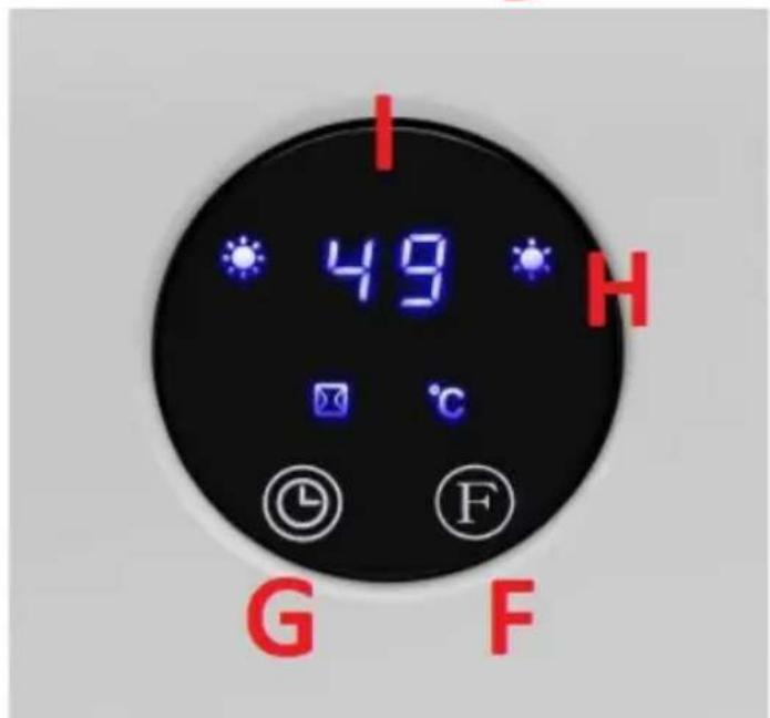
text_image
I 49 H G Fnatural_image
Close-up of a white air conditioner unit showing ventilation grilles and a side view with red arrows pointing to features (no text or symbols visible)text_image
a b c d e SET f - g OK + h i j k l m n TIME /ON EDIT TIME /OFF UNIPRODOtext_image
F P I II °C Ftext_image
F P I II C S ① ② ③ ④text_image
F I II P Ctext_image
F I II P °C 08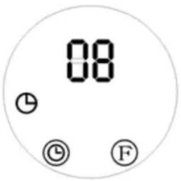
text_image
08 ① ◎ Ftext_image
F I II P ℃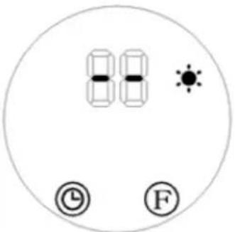
text_image
88 - - - - - - - - - - - - - - - - - - - - - - - - - - - - - - - - - - - - - - - - - - - - - - - - - - - - - - - - - - - - - - -text_image
F P I II C Ftext_image
89 °C © Ftext_image
F I P 88 88 P C Ftext_image
F P 88 P Ftext_image
88 °C © FThis User Manual has been translated for your convenience using machine translation. Reasonable efforts have been made to provide an accurate translation; however, no automated translation is perfect nor is it intended to replace human translators. The official User Manual is the English version. Any discrepancies or differences created in the translation are not binding and have no legal effect for compliance or enforcement purposes. If any questions arise related to the accuracy of the information contained in the User Manual, please refer to the English version of those contents which is the official version.
Technical Data
| Parameter description | Parameter value | |
| Product name | Ceramic wall heater | |
| Model | UNI_HEATER_09 | UNI_HEATER_10 |
| Supply voltage [V~] / Frequency [Hz] | 230/50 | |
| Rated power [W]. | 1000-2000 (min-max) | |
| Safety class | II | |
| IP class | IP22 | IPX2 |
| Dimensions [width x depth x height; mm] | 510 x 120 x 230 535 x 110 x 195 | |
| Weight [kg] | 2.4 | 2.4 |
| Temperature control range [°C] | 10-49 | |
| Remote control | Yes | |
| Battery type for the remote | CR 2025 3V | |
| Heating area [m2] | 10-15 | |
1. General Description
This manual is intended to assist you for safe and reliable use. The product is designed and manufactured strictly according to technical specifications using the latest technology and components and maintaining the highest quality standards.
CAREFULLY READ AND UNDERSTAND THIS MANUAL BEFORE STARTING THE WORK.
To ensure long and reliable operation of the device, make sure to operate and maintain it properly in accordance with the guidelines in this instruction manual. The technical data and specifications in this manual are up-to-date. The manufacturer reserves the
right to make changes in order to improve the quality. Taking the technical progress and the possibility of reducing noise into account, the unit is designed and built in such a way so that risks resulting from noise emissions are reduced to the lowest possible level.
Explanation of symbols
| CE | The product complies with applicable safety standards. |
 | Read the manual before use. |
 | Recyclable product. |
 | CAUTION! or WARNING! or REMEMBER! describing a situation (general warning sign). |
 | CAUTION! Risk of electric shock! |
 | Safety class II equipment with double insulation. |
 | Caution! Hot surface can cause burns! |
 | For indoor use only. |
 | Do not cover the unit with any materials or objects. |
EN
CAUTION! The figures in this manual are illustrative only and may vary in some details from the actual appearance of the product.
2. Safety of use
CAUTION! Read all safety warnings and instructions. Failure to follow the warnings and instructions may result in electric shock, fire and/or serious injury or death.
The term "device" or "product" in the warnings and in the description of the instructions refers to
Ceramic wall heater
2.1. Electrical safety
a) The plug of this device must fit into the outlet. Do not modify the plug in any way. Original plugs and matching outlets reduce the risk of electric shock.
b) Avoid touching grounded parts, such as pipes, heaters, ovens, and refrigerators. There is an increased risk of electric shock if your body is grounded and touches the device while exposed to direct rain, wet pavement, or while working in a damp environment. If water enters the device, there is an increased risk of damage to the unit and electric shock.
c) Do not touch the device with wet or damp hands.
d) Do not use the cord in an unintended manner. Never use it to carry the device or to pull the plug out of the socket. Keep the cord away from heat sources, oil, sharp edges or moving parts. Damaged or tangled cords increase the risk of electric shock.
e) If you cannot avoid using the product in a wet environment, use a residual current device (RCD) to connect it to electrical mains. Using an RCD reduces the risk of electric shock.
f) Do not use the device if the power cord is damaged or shows signs of wear. A damaged power cord should be replaced by a qualified electrician or the manufacturer's service department.
g) To avoid electric shock, do not immerse the cable, plug, or the device itself in water or other liquid. Do not use the appliance on wet surfaces.
h) CAUTION – DANGER TO LIFE! When cleaning or using the appliance, never immerse it in water or other liquids.
i) Do not use the appliance in rooms with very high humidity / in the immediate vicinity of water tanks!
j) Do not allow the machine to get wet. Risk of electric shock!
2.2. Safety in the workplace
a) If you find any damage or irregularities in the operation of the product, immediately turn it off and report it to an authorized person.
b) If you have any doubts as to whether the product is working properly or if it is damaged, contact the manufacturer's service department.
c) Repairs to the device may only be carried out by the manufacturer's service. Do not attempt to repair the product on your own!
d) In the event of ignition or a fire, use dry powder or CO2 extinguishers only to suppress the fire of the appliance is live.
e) Check the condition of the safety stickers regularly. Replace them if they are illegible.
f) Keep these instructions for use for future reference. If the product is to be handed over to a third party, hand it over with this user manual.
g) Keep packaging components and small installation parts out of the reach of children.
2.3. Personal safety
a) Do not operate this device if you are tired, ill or under the influence of alcohol, drugs or medication that could impair your ability to operate the device.
b) The device is not intended to be used by persons (including children) with reduced mental, sensory or intellectual functions or persons who lack experience and/or knowledge unless they are supervised or have been instructed by a person responsible for their safety on how to operate the device.
c) To prevent accidental start-up, make sure the switch is in the off position before connecting to a power source.
d) The product is not a toy. Children should be watched to ensure that they do not play with the product.
e) Do not place your hands or any objects inside the running device!
2.4. Safe use of the device
a) Do not use the device if the ON/OFF switch does not function properly (does not turn on and off). Units that cannot be controlled by the switch are unsafe, cannot operate, and must be repaired.
b) Disconnect the device from the power supply before adjusting, cleaning, or servicing. This precaution reduces the risk of accidental start-up.
c) Keep unused product out of the reach of children and anyone unfamiliar with the device or this manual. Products are dangerous when used by inexperienced users.
d) Keep the product in good working order. Check before each use for general damage or damage to moving parts (cracks in parts and components or any other condition that may affect the safe operation of the device). If damaged, have the device repaired before use.
e) Repairs and maintenance should be carried out by qualified personnel using only original spare parts. This will ensure the safety of use.
f) To ensure the designed operational integrity of the device, do not remove factory-installed covers or loosen screws.
g) When transporting or moving the device from storage to the place of use, observe the health and safety rules for manual handling applicable in the country where the device is used.
h) Do not touch any moving parts or accessories unless the device is unplugged.
i) Do not move, shift, or rotate the device while in operation.
j) Clean the device regularly to prevent permanent dirt build-up.
k) Do not obstruct the air inlet or outlet.
I) The product is not a toy. Cleaning and maintenance must not be performed by children without adult supervision.
m) Do not tamper with the device to alter its performance or design.
n) Keep the unit away from sources of fire and heat.
o) Do not block the ventilation openings of the unit!

CAUTION! Although the product has been designed to be safe and has adequate safeguards and despite the additional safety features provided to the user, there is still a slight risk of accident or injury when handling the product. Caution and common sense are advised when using the product.
3. Instructions for use
The product is intended for room heating.
The user is responsible for any damage resulting from misuse.
EN
3.1. Product overview
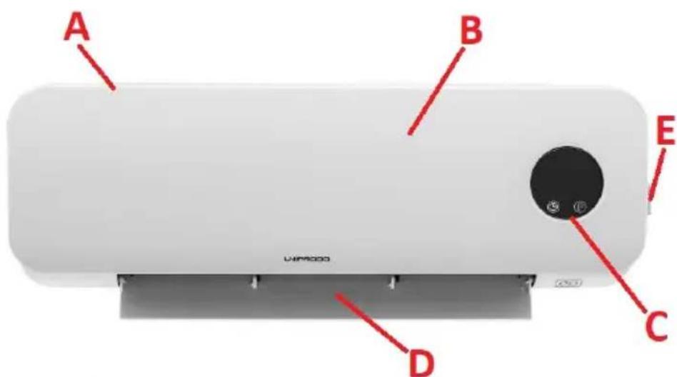
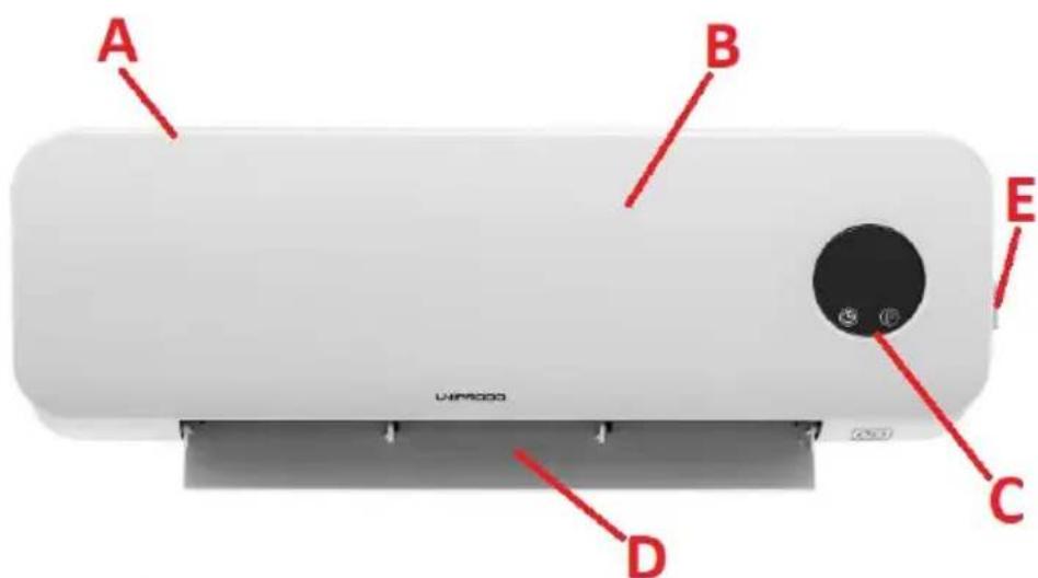
UNI_HEATER_09
UNI_HEATER_10

text_image
A B E C D LIM5000
text_image
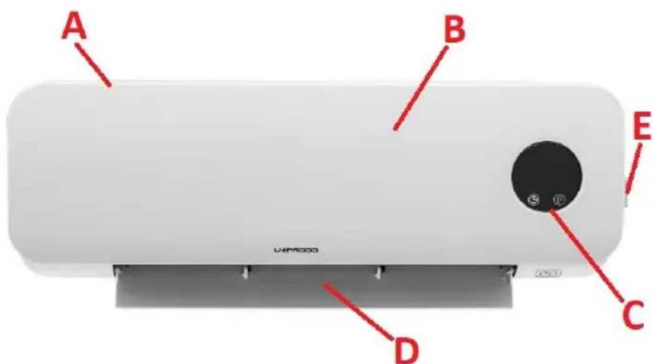
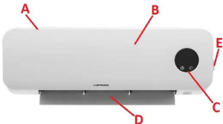
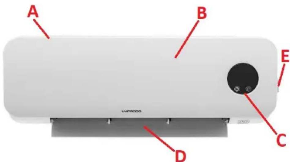
I 49 H G FA. Air intake / ventilation inlet (not shown)
B. Casing
C. Control panel
D. Air supply outlet with control flap
E. Power switch
F. Function selection button
G. Timer button
H. Device control lamps
I. Display
J. Receiver for the remote control
3.2. Preparation for operation
POSITIONING OF THE UNIT
The ambient temperature must not exceed 40^ C and ambient humidity should not exceed 85%. The unit should be mounted on a vertical, stable wall in a way that ensures good air circulation. Keep the unit away from any hot and humid surfaces. Always operate the unit on a stable, clean, fireproof and dry surface and out of the reach of children and persons with impaired mental, sensory and intellectual functions. It is forbidden to use the device in the immediate vicinity of bathtubs, showers, swimming pools! Place the unit in such a way that the mains plug can be reached at any time. Ensure that the power supply to the unit corresponds to that specified on the identification plate! During installation, the building and installation regulations in force in a given region should also be taken into account.
ASSEMBLY OF THE DEVICE
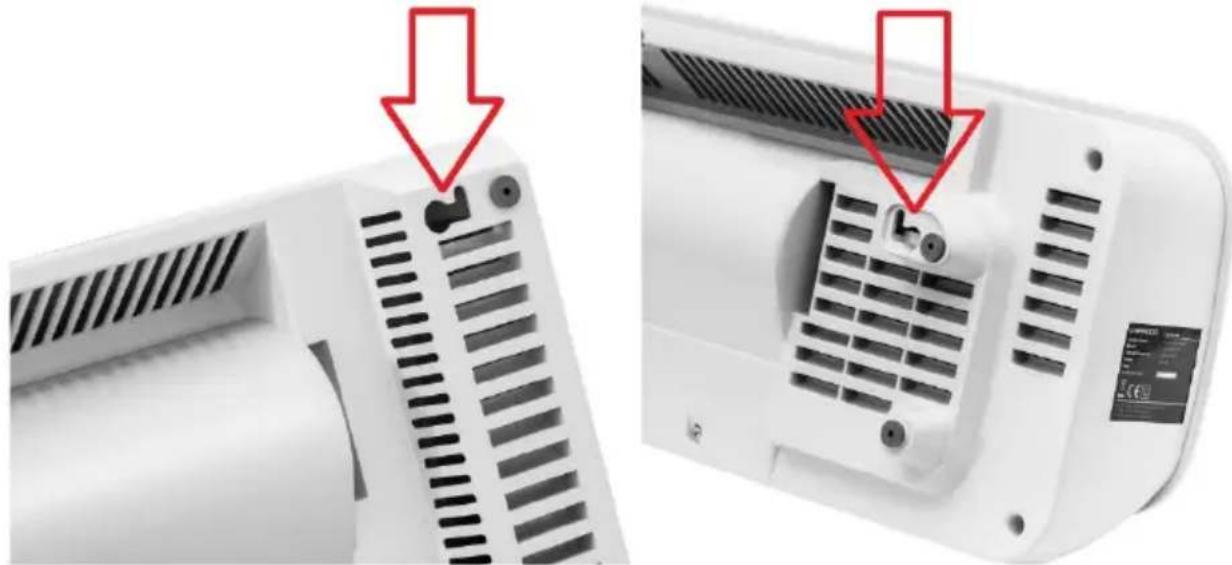
Attach the device to a vertical wall with expansion bolts and special catches/hooks - use the special holes on the back of the device (see the pictures below).
natural_image
Close-up of a white air conditioner unit showing vent slots and ventilation grilles, with red arrows pointing to the ports (no text or symbols visible)The minimum height of the mounting holes from the floor should be 1.8 m for the UNI_HEATER_09 model and 2.05 m for the UNI_HEATER_10 model.
3.3. Working with the device
text_image
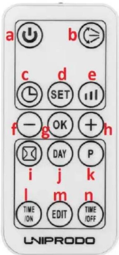
a b c d e SET f - g OK + h i j k l m n TIME /ON EDIT TIME /OFF UNIPRODOa) Device on/off button
b) Air supply flap start/stop button
c) Timer on/off button
d) Time and day setting button
e) Heating level button
f) Button for decreasing the value of a given parameter
g) Button for confirming a given parameter
h) Button for increasing the value of a given parameter
i) Open window detection on/off button
j) Day selection button (for automatic operation)
k) Automatic operation programming start button
I) Auto-on button
m) Edit button
n) Automatic shutdown setting button
3.3.1 Startup
Connect the device to the power socket and set the power switch (E) to the "I" position - the device will go into standby mode and the display (I) will show the message "S."
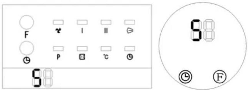
text_image
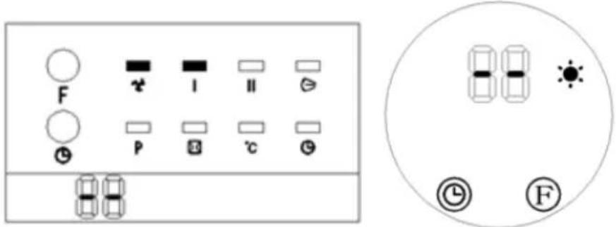
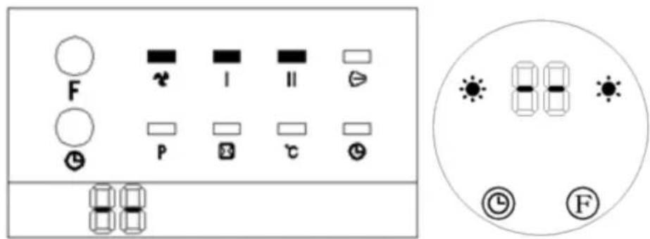
F P I II ℃ 8:00 8:00 ① ② ③ FPress the function selection button (F) on the control panel to go to the airflow settings option. The display will show the value "-" (see pictures below) and the UNI_HEATER_09 model's fan indicator will light up (see the picture below on the left):

text_image
F P I II ℃ ② ③ ④ ⑤ ⑥ ⑦ ⑧Pressing the function selection button (F) again starts the heating at a low power level, which is additionally indicated by the appropriate indicator on the control panel in both models:
text_image
F P I II °C FPressing the function selection button (F) for the third time will increase the heating power, which will also be signaled by an indicator on the control panel:

text_image
F P I II C S ① ② ③Pressing the function selection button (F) for the fourth time will, in addition to high-power heating, additionally activate the airflow flap (D). Activation of the airflow flap in the UNI_HEATER_09 model will be additionally signaled by an additional indicator:
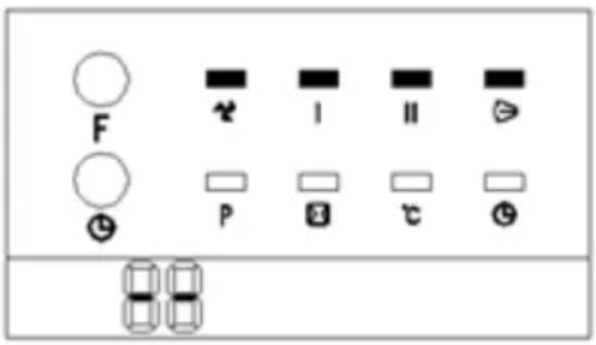
text_image
F I II P CPressing the function selection button (F) for the fifth time will turn off the heating and switch to standby mode - the fan will turn off within the next 30 seconds. The message "S" will appear on the display of the control panel, the same as after starting the device (see the first pictures of the panels above), and all the indicators will go out.
3.3.2 Timer setting
Press the timer button on the control panel (G) or the remote control (C) to set the timer from 00-12 hours to indicate automatic shutdown - the timer light will light up on the display (see pictures below). Each press of this button increases the time by 1 hour. After setting the time, the display will show the currently set time for 5 seconds. Then the display will revert to showing the previous value:
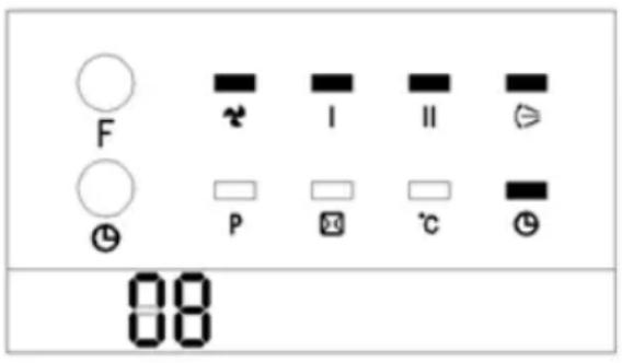
text_image
F I II P ℃ 08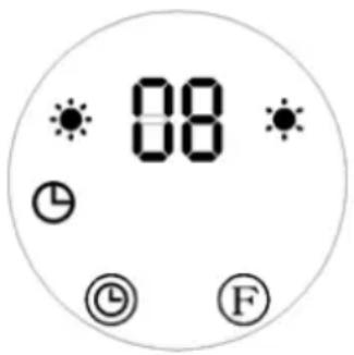
text_image
08 ① ② ③ F3.3.3 Setting the switch-on time
In standby mode, pressing the timer button on the control panel (G) or the remote control (C) will allow you to set the delay time for the automatic start-up of the unit in the range of 1-12 hours. Once set, the display will show the time to switch-on and the timer indicator will be illuminated (see the pictures below). The remaining time will be indicated with a countdown every hour. After the set time has elapsed, the device will start up with the default temperature of 23^ C.
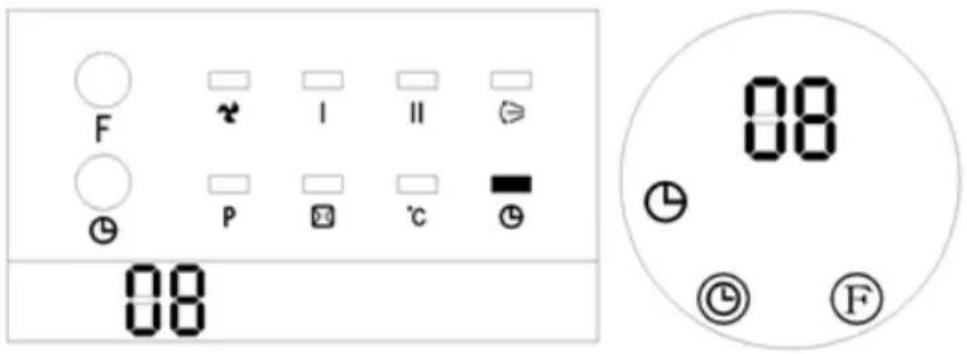
text_image
F P I II ℃ 08 08 ① ② ③ FIMPORTANT: in the absence of a specific temperature and weekly program setting, the unit will turn off after 12 hours of continuous operation and enter standby mode.
3.3.4 Controlling the device with the remote control
NOTE: the operating range of the remote control reaches 3 m and the signal reception angle is below 60° right/left.
Pressing the on/off button on the remote control (a) turns on the unit and triggers the airflow. The display will show the message "-" and the UNI_HEATER_09 fan indicator will be additionally illuminated (picture below left):

text_image
F P I II C ① ② ③ ④Pressing the heating level button (e) once will activate the heating at a lower power level and the relevant indicators will light up on the display:
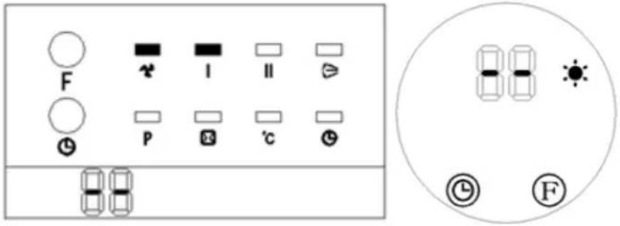
text_image
F P I II °C FPressing the heating level button (e) twice starts the heating level with higher power:
text_image
F P I II C FPressing the heating level button (e) again turns off the heating, ventilation stops after approx. 30 seconds and the device goes into standby mode.
The function of the timer button (c) works in the same way as from the control panel (see the description above).
The air supply flap button (b) switches it on or off by pressing it. In the UNI_HEATER_09 model, the activation of the flap is confirmed by the corresponding indicator on the control panel - the same icon as on the button of this function on the remote control.
3.3.5 Setting the day/time
IMPORTANT: day/time settings can be changed both in standby mode and during operation.
- Press the time and day setting button (d) on the remote control, and the display will show the default value, e.g. "12."
- Use the parameter decrease/increase (f/h) buttons to set the current hour (selection range 0-24).
• After setting the hour, press the time/day button (d) again to move to the minute setting and use the parameter decrease/increase buttons (f/h) to set the current minute (selection range 00-59). - As soon as you set the time, press the button used for setting the time and day (d) to choose the current day of the week. The display will show the message "d1", where:
d1 = Monday; d2 = Tuesday, d3 = Wednesday, etc. until Sunday = d7.
Set the current day of the week using the buttons for decreasing/increasing the value of the parameter (f/h). Then use the button for confirming the value (g) to approve the selected values. The display will revert to showing the previous information as before changing the settings.
For example, if we set Wednesday, 9:30 a.m., heating at 25^ C with high power, the setting diagram will look like this for a given model:
- To check the currently set day and time, press the time/day setting button (d).
IMPORTANT: the time and date settings will be saved in the device's memory. They will be lost only in the event of turning the power switch to the "O" position or a power loss, e.g. sudden disconnection of the power plug from the socket.
3.3.5 Setting the temperature or canceling the setting
- With the unit on, press the button to increase or decrease the value of a given parameter (h or f), and the display will show the default temperature setting.
- The same buttons on the remote control (h or f) can be used to set a different target temperature within the allowable range (see the technical data table).
- Use the value confirmation button (g) to save the newly set value that is currently displayed.
- To delete the previously set temperature, press the heat level button (e) to select one of the two available heating levels (described earlier). Then the display will show "-" and the temperature light will turn off, while the indicator of the selected heating level will be illuminated.
IMPORTANT: after 12 hours of continuous operation in one of these two modes, the device will turn off automatically (the fan will continue to run for 30 seconds) and will go into standby mode.
3.3.6 Remarks on temperature settings and operation of the device
- If the difference between the set temperature and the ambient temperature is >2^ C , the unit works at full power. If this difference is <2^ C , the unit operates at lower power.
- When the temperature set on the unit is equal to the ambient temperature, the fan will run for another 30 seconds to cool down the unit inside and then the unit will go into standby mode.
- When the temperature in the ambient standby mode drops below 2^ C in relation to the temperature set on the device, it will turn on automatically and start heating.
3.3.7 Setting the weekly program
- The device must be turned on with the time and day of the week previously set (see more under "Setting the day/time")
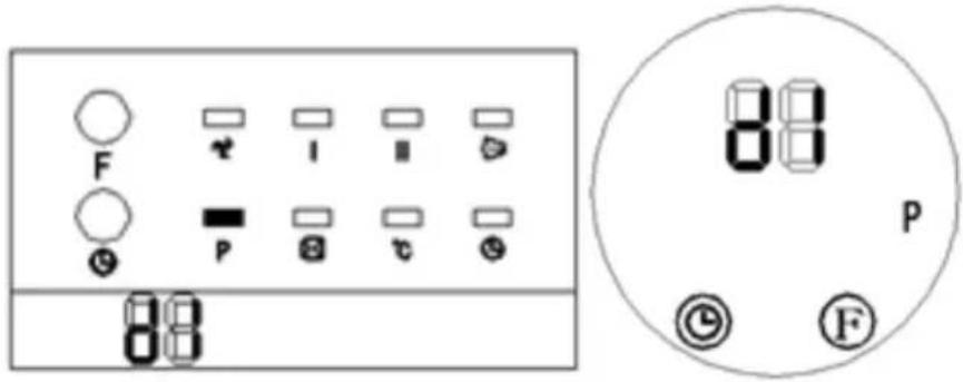
- Press the automatic operation start button (k), the "P" light will be on and the unit will enter the weekly program setting.
- Press the day mode button (j) and the display will show "d1" to "d7" (the corresponding day of the week, i.e. Monday to Sunday). Select a specific day of the week, e.g. Monday = "d1", Tuesday = "d2" etc.:
text_image
F P 88 88 P C F- With the selected day, press the button for editing the day of the week (m), and the display will show up to 6 available time programs (P1-P6) for that day, all of which can be programmed:

text_image
F P 88 P G F- Press the auto-start setting button (I) to select the time to start the unit. Press the same button all the time to select the hour in the range 0-24, e.g. for 7:00, and the display will show:
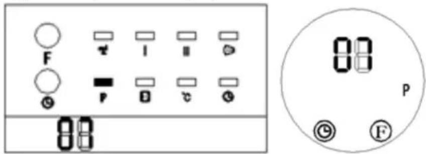
text_image
F P 88 88 P F- Press the auto-off button (n) and the display will show the previously set auto-off time. If you want to change it, press the same button (n) again and, just as with the time of switching on, set the automatic switch-off time (0-24), bearing in mind that the switch-off time must not be earlier than the switch-on time. NOTE: setting the same switch-on and switch-off time will put the device into standby mode!
- [Only in UNI_HEATER_10] Use the buttons for increasing and decreasing the value of a given parameter (h or f) to set the target temperature. Next, save it in the device's memory with the confirmation button (g).
- Repeat the above steps if necessary for the remaining days to program the entire working week, including individual days, on and off times.
- [Only in UNI_HEATER_09] After programming the previous steps according to the above, press the day selection button (j) to set the day of the week to start the automatic operation. Then select the time of switching on with the edit button (m). With the buttons for increasing and decreasing the value of a parameter (h or f), select the target temperature and save it in the device's memory with the confirmation button (g).
- Press the automatic operation programming button (k) to activate or deactivate the automatic weekly program (the corresponding light on the control panel will be on or off).
IMPORTANT: during automatic weekly operation according to the programmed schedule, pressing the buttons (j, l, m, n) allows you to check the time settings for a specific day and its set time interval program.
If no specific heating temperature is set, its default value is 23^ C.
However, when the ambient temperature is higher than that set on the device, it will not start up.
When the power is turned off, the automatic weekly program will be lost.
3.3.8 "Open window" detection function
With this function ison, when the ambient temperature drops by 5-10°C within 10 minutes, the device will turn off the heating and switch to standby mode.
To start the open window detection function, press the on/off button of this function (i) on the panel of a turned-on, warmed-up device (it must work a bit on heating). Then the appropriate indicator will light up to indicate its activation:

text_image
F P I II ℃ 83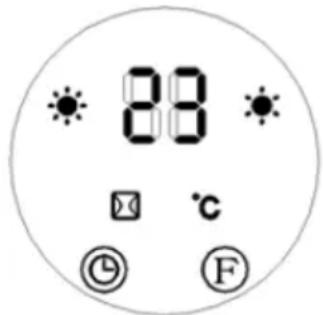
text_image
88 ℃ © FBy default, the target heating temperature is set to 23^ C. To change it, set the desired value with the buttons for decreasing/increasing the value of the parameter (f/h).
To deactivate the open window detection function, press the function button on the remote control again. The function indicator on the control panel will turn off.
3.4. Cleaning and maintenance
a) Pull the mains plug and let the unit cool down completely before cleaning, adjusting or replacing accessories and when the unit is not in use.
- Wait until the rotating parts stop.
b) Use only non-corrosive cleaning agents for cleaning the surfaces.
c) Do not spray the unit with a stream of water or immerse it in water.
d) Make sure that no water enters through the ventilation openings in the casing.
e) Clean the ventilation openings with a brush and compressed air.
f) Use a soft, damp cloth for cleaning.
g) Remove the battery from the appliance if you do not intend to use it for a long time.
h) Do not use sharp and/or metal objects (e.g. wire brush or metal spatula) for cleaning as they may damage the surface of the appliance material.
i) Do not clean the device with acidic substances, medical products, thinners, fuel, oil or other chemicals as this may damage the device.
j) In case the device does not fully respond to the remote control, check the condition of the battery and, if necessary, replace it with a new, functional one.
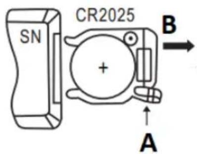
To replace the batteries of the remote control, press the latch of the battery compartment (at the bottom of the remote control at its back) and pull out the compartment with the battery. When replacing the battery, pay attention to the correct polarity according to the diagram on the back of the remote control housing.
text_image
SN CR2025 + A BINSTRUCTIONS FOR THE SAFE DISPOSAL OF BATTERIES.
A CR 2025 3V battery is installed in the remote control.
Remove used batteries from the unit in the same way you put them in.
Return the batteries to a unit responsible for their disposal.
DISPOSAL OF WASTE APPLIANCES
At the end of its useful life, this product should not be disposed of with normal household waste but should be taken to a collection point for the recycling of electrical and electronic equipment. This is indicated by the symbol on the product, operating instructions or packaging. The materials used in this appliance are recyclable according to their marking. By reuse, recycling or applying other forms of use of waste machines, you make a significant contribution to the protection of our environment.
Your local administration will provide you with information about the appropriate disposal point for used appliances.

text_image
A UNPROD B C D
text_image
F G H 49 I J E UNI_HEATER_10 A B E C D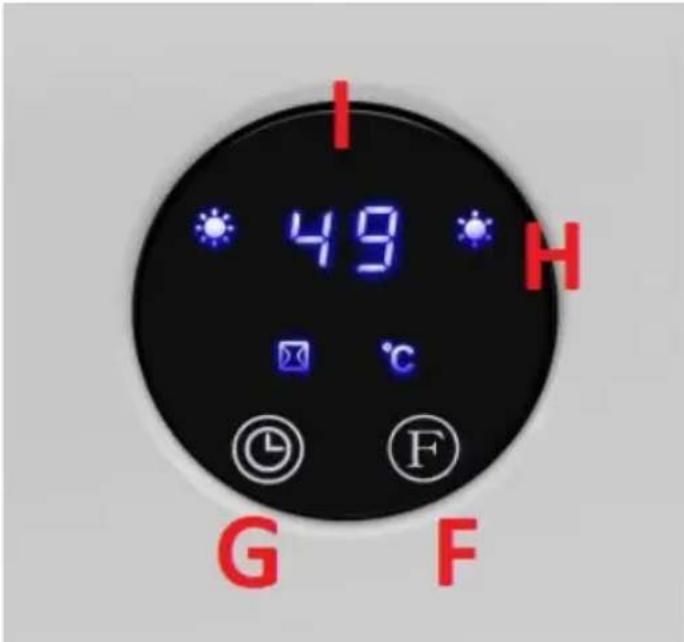
text_image
I 49 H G Fnatural_image
Close-up of a white air conditioner unit showing ventilation grilles and a close-up of its back panel (no text or symbols visible)text_image
a b c d e l SET ll f - g OK + h i j k l m n TIME /ON EDIT TIME /OFF UNIPRODOtext_image
F I II P Ctext_image
F P I II C ① ② ③ ④text_image
F P I II °C Ftext_image
F P I II C Ftext_image
F P I II 09 30 83 26
text_image
* 88 * © F * 88 * © F * 88 * © F * 89 * © F °Ctext_image
F P 88 P Ftext_image
F P I II C P S C G 88 88 P @ Ftext_image
F P 88 P Ftext_image
F G F P I II C H 4.9 I J EUNI_HEATER_10
text_image
A B E C D LIM5000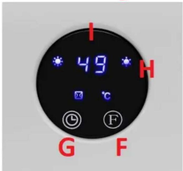
text_image
I 49 H G Fnatural_image
Close-up of a white air conditioner unit showing vent slots and ventilation grilles, with red arrows pointing to the ports (no text or symbols visible)text_image
a b c d e SET f - g OK + h i j k l m n TIME /ON EDIT TIME /OFF UNIPRODOtext_image
F P I II ℃ 8:8 8:8 ⑨ ⑤ Ftext_image
F P I II °C Ftext_image
F P I II C S B Ftext_image
F P I II C ⊗text_image
F I II P °C 08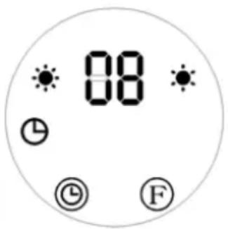
text_image
08 ① ② ③ Ftext_image
F I II P °C 08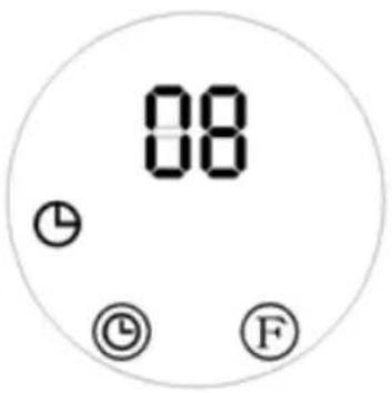
text_image
08 ① ◎ Ftext_image
F I II P ℃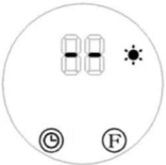
text_image
8:10 8:20 8:30 © Ftext_image
F P I II C Ftext_image
F P 88 88 P Ftext_image
F I II P C 88 88 P ② ⑤ ⑧text_image
F P 88 88 P @ Ftext_image
88 ℃ © ⓕ Ftext_image
A UNPROD B C D
text_image
F G 49 I J E UNI_HEATER_10 A B E C D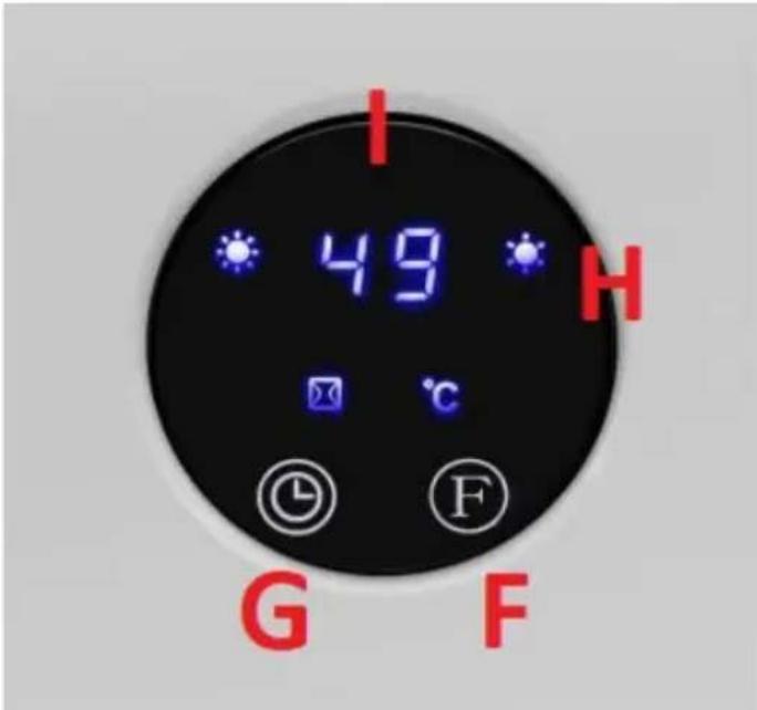
text_image
I 49 H G Fnatural_image
Close-up of a white air conditioner unit showing ventilation grilles and a close-up of its back panel (no text or symbols visible)text_image
a b c d e l SET ll f - g OK + h i j k l m n TIME ON EDIT TIME OFF UNIPRODOtext_image
F P I II C S Ftext_image
F P I II Ctext_image
F P I II C @ Ftext_image
F P I II °C Ftext_image
F P I II C Ftext_image
* 89 * © F * 88 * © F * 88 * © F * 89 * © F °Ctext_image
F P 88 P Ftext_image
F P I II C 88 P @ Ftext_image
F P 88 P Ftext_image
A UNPROD B C D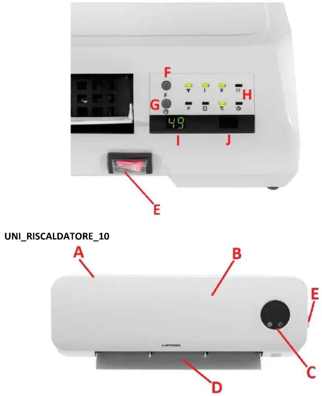
text_image
UNI_RISCALDATORE_10 A B C D E F G H 49 I J
text_image
I 49 H G Fnatural_image
Close-up of a white air conditioner unit showing ventilation grilles and a close-up view with red arrows pointing to features (no text or symbols visible)text_image
a b c d e l SET ll f - g OK + h i j k l m n TIME ON EDIT TIME OFF UNIPRODOtext_image
F P I II ℃ 8:8 8:8 ① ② Ftext_image
F P I II ℃ © © Ftext_image
F I II P Ctext_image
F P I II C ① ② ③ ④text_image
F P I II °C Ftext_image
F P I II C Ftext_image
F # I II # # p #1 #2 # 09 80 F # I II # # p #2 #3 83 F # I II # # p #3 #4 86
text_image
* 09 * © F * 88 * © F * 88 * © F * 89 * © F °Ctext_image
F P 88 88 P C Ftext_image
F 88 P © © Ftext_image
A UNPROD B C D
text_image
F G H 49 I J E UNI_CALENTADOR_10 A B E C D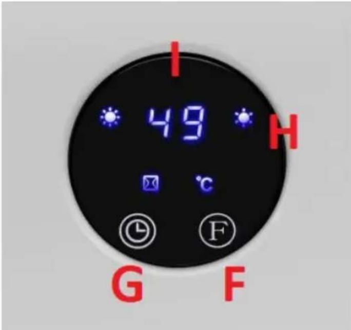
text_image
I 49 H G Fnatural_image
Close-up of a white air conditioner unit showing ventilation grilles and a side view with red arrows pointing to features (no text or symbols visible)text_image
a b c d e SET f - g OK + h i j k l m n TIME /ON EDIT TIME /OFF UNIPRODOtext_image
F P I II ℃ 8:8 8:8 ① ⑤ Ftext_image
F I II P Ctext_image
F P I II C C Ftext_image
F P I II °C Ftext_image
F P I II C Ftext_image
F P I II # 89 88 88 86
text_image
* 88 * © F * 88 * © F * 88 * © F * 88 * © F °Ctext_image
F P 88 88 P Ftext_image
88 ℃ © ⓕ Ftext_image
A UNPROO B D C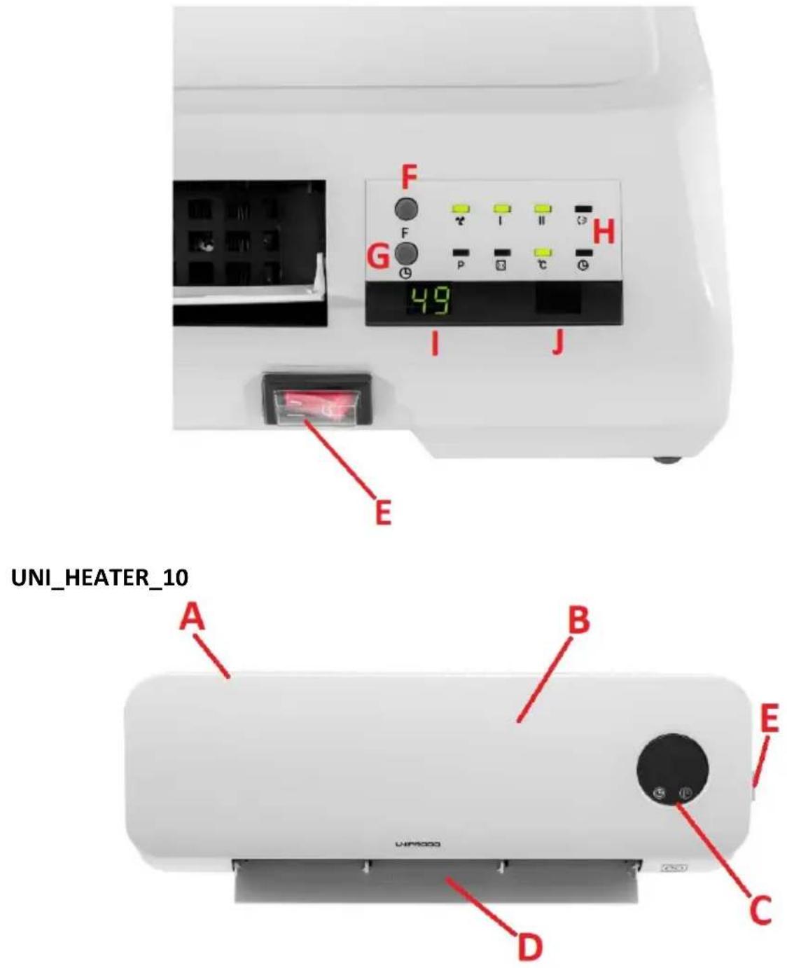
text_image
F G H 49 I J E UNI_HEATER_10 A B E C D
text_image
I 49 H G Fnatural_image
Close-up of a white air conditioner unit showing vent slots and ventilation grilles, with red arrows pointing to the ports (no text or symbols visible)text_image
a b c d e SET f - g OK + h i j k l m n TIME ON EDIT TIME OFF UNIPRODOtext_image
F P I II C C C C Ftext_image
F P C S Ftext_image
F P I II Ctext_image
F P I II C Ftext_image
F P I II °C Ftext_image
F P I II C Ftext_image
F P I II Ø Ø 89 88 88 88 F P I II Ø Ø F P I II Ø Ø F P I II Ø
text_image
* 89 * © F * 88 * © F * 83 * © F * 85 * © F °Ctext_image
F P 88 88 P Ftext_image
F I II P C 88 88 P © Ftext_image
F G F I II H P C 49 I J EUNI_HEATER_10
text_image
A B E C D LIM5000
text_image
I 49 H G FAPPARATETS PLACERING
natural_image
Close-up of a white air conditioner unit showing vent slots and ventilation grilles, with red arrows pointing to the ports (no text or symbols visible)text_image
a b c d e SET f - g OK + h i j k l m n TIME /ON EDIT TIME /OFF UNIPRODOtext_image
F P I II ℃ G G G G Gtext_image
F P I II °C Ftext_image
F P I II C S ① ② ③text_image
F P I II Ctext_image
F I II P °C 08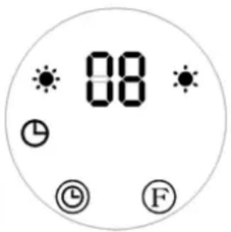
text_image
08 ① ② ③ Ftext_image
F I II P °C 08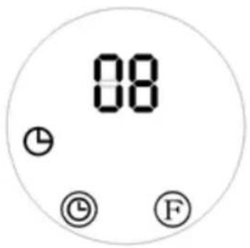
text_image
08 ① © Ftext_image
F P I II C ⊗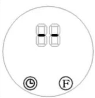
text_image
88 © Ftext_image
F I II P ℃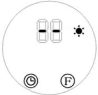
natural_image
Circular icon with two cars, a sun, and clock symbols (no text or numbers)text_image
F P I II C Ftext_image
F P 88 P Ftext_image
F P 88 88 P Ftext_image
88 ℃ © ⓕ Ftext_image
A UNPROO B D C
text_image
F G I J 4.9 EUNI_HEATER_10
text_image
A B E C D LIM5000
text_image
I 49 H G Fnatural_image
Close-up of a white air conditioner unit showing vent slots and ventilation grilles, with red arrows pointing to the ports (no text or symbols visible)text_image
a b c d e SET f - g OK + h i j k l m n TIME /ON EDIT TIME /OFF UNIPRODOtext_image
F P I II ℃ G G G G Gtext_image
F P I II °C Ftext_image
F P I II C FFI
text_image
F P I II C © © Ftext_image
F P I II °C Ftext_image
F P I II C Ftext_image
89 °C © Ftext_image
F P 88 P Ftext_image
F P 88 P Ftext_image
F P 88 88 P @ Ftext_image
88 ℃ © ⓕ Ftext_image
A UNPROD B C D
text_image
F G H 49 I J E UNI_HEATER_10 A B E C D
text_image
I 49 H G Fnatural_image
Close-up of a white air conditioner unit showing vent slots and ventilation grilles, with red arrows pointing to the ports (no text or symbols visible)text_image
a b c d e l SET ll f - g OK + h i DAY P l j k TIME m n /ON EDIT TIME /OFF UNIPRODOtext_image
F P I II ℃ 8:8 8:8 ① ② Ftext_image
F I II P Ctext_image
F P I II C Ftext_image
F P I II C Ftext_image
F P I II C Ftext_image
F P I II # 89 88 88 88
text_image
* 88 * © F * 88 * © F * 88 * © F * 88 * © F °Ctext_image
F P 88 P Ftext_image
F P 88 P G G Ftext_image
88 °C © Ftext_image
A UNPROO B D C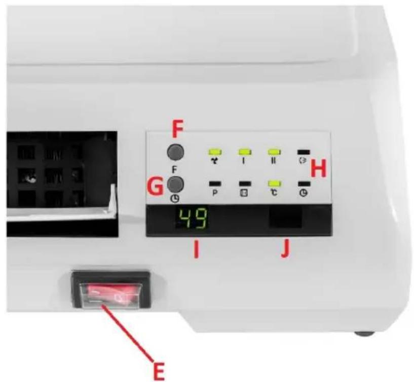
text_image
F G I J 4.9 EUNI_HEATER_10
text_image
A B E C D LIM5000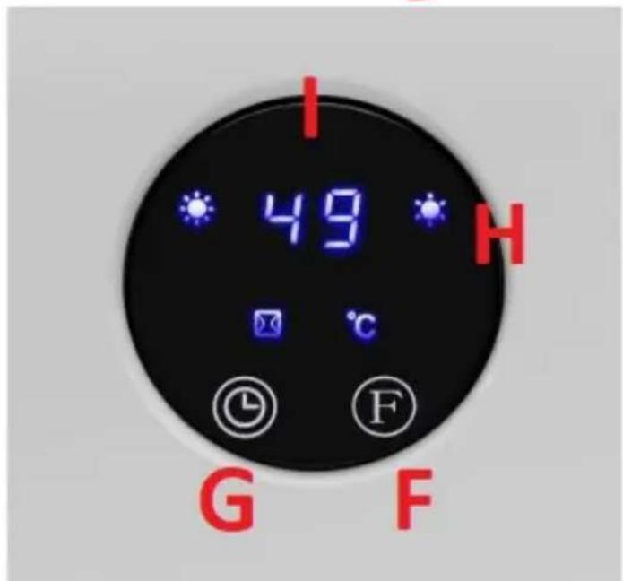
text_image
I 49 H G Fnatural_image
Close-up of a white air conditioner unit showing vent slots and ventilation grilles, with red arrows pointing to the ports (no text or symbols visible)text_image
a b c d e f - g OK + h i j k l m n TIME /ON EDIT TIME /OFF UNIPRODOa) Av/på-knapp for enheten
b) Start/stopp-knapp for lufttilførsel
c) Timer på/av-knapp
d) Innstillingsknapp for tid og dag
e) Oppvarmingsnivåknapp
f) Knapp for å redusere verdien av en gitt parameter
g) Knapp for å bekrefte en gitt parameter
h) Knapp for å øke verdien av en gitt parameter
i) Åpne vindusdeteksjon av/på-knapp
j) Dagvalgknapp (for automatisk drift)
k) Startknapp for automatisk driftsprogrammering
I) Auto-på-knapp
m) Rediger-knapp
n) Innstillingsknapp for automatisk avstenging
3.3.1 Oppstart
text_image
F P I II ℃ 8:8 8:8 ⑨ ⑤ Ftext_image
F P I II °C Ftext_image
F P C S Ftext_image
F P I II Ctext_image
F I II P °C 08
text_image
08 ① © Ftext_image
F I II P ℃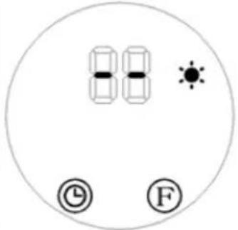
natural_image
Circular icon with two cars, a sun, and clock symbols (no text or numbers)text_image
F P I II C F3.3.7 Stille inn ukeprogram
text_image
F P 88 P Ftext_image
F 88 P @ Ftext_image
F P 88 88 P @ Ftext_image
88 °C © Ftext_image
A B UNIPROOR D C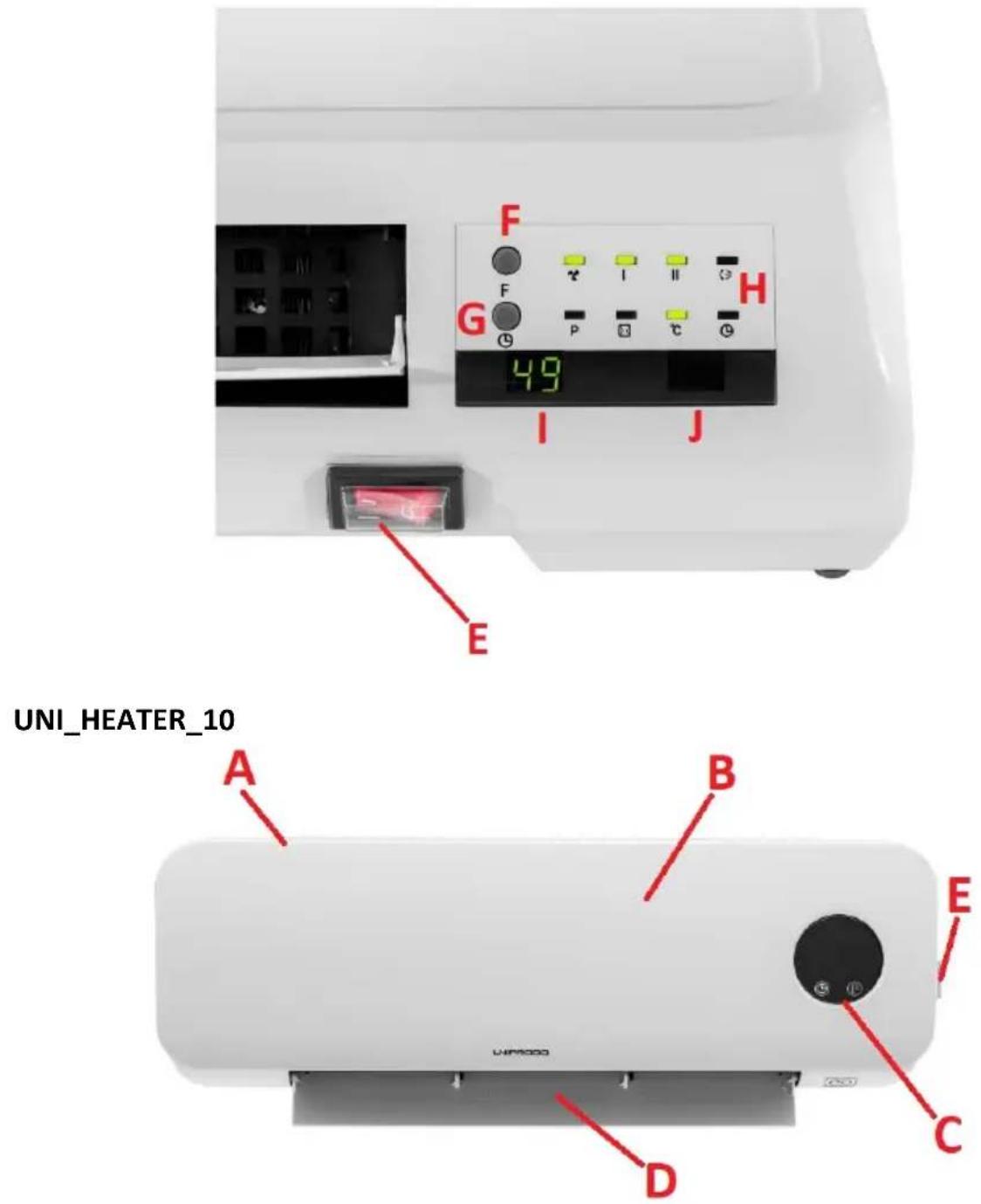
text_image
F G 49 I J E UNI_HEATER_10 A B E C D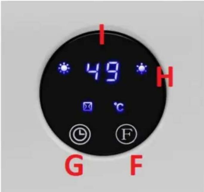
text_image
I 49 H G FA. Luftintag/ventilationsintag (ej visat)
B. Hölje
C. Kontrollpanel
PLACERING AV APPARATEN
natural_image
Close-up of a white electric air conditioner unit showing ventilation grilles and mounting holes, with red arrows pointing to features (no text or symbols visible)text_image
a b c d e l SET ll f - g OK + h i j k l m n TIME /ON EDIT TIME /OFF UNIPRODOtext_image
F P I II ℃ ②
text_image
88 © Ftext_image
F P I II C G S - - - - - - © Ftext_image
F P I II Ctext_image
F P I II C @ Ftext_image
F P I II °C Ftext_image
F P I II C Ftext_image
F P I II # 09 88 88 26
text_image
* 88 * © F * 88 * © F * 88 * © F * 88 * © F °Ctext_image
F P 88 88 P Ftext_image
F I II P C 88 88 P © Ftext_image
F I II P D C 88 88 P © Ftext_image
88 ℃ © ⓕ Ftext_image
A UNPROO B D C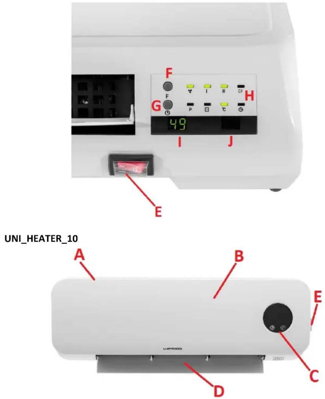
text_image
F G 49 I J E UNI_HEATER_10 A B E C D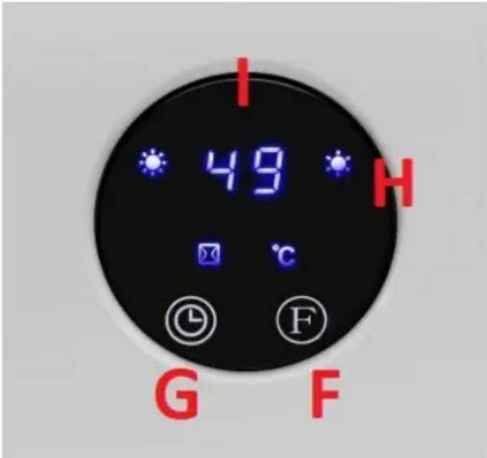
text_image
I 49 H G Fnatural_image
Close-up of a white air conditioner unit showing ventilation grilles and a close-up of its back panel (no text or symbols visible)text_image
a b c d e l SET ll f - g OK + h i j k l m n TIME ON EDIT TIME OFF UNIPRODOtext_image
F P I II ℃ 8:8 8:8 ① ⑤ Ftext_image
F P I II Ctext_image
F P I II C @ Ftext_image
F P I II °C Ftext_image
F P I II C Ftext_image
F P I II Ø Ø 09 88 88 86 F P I II Ø Ø F P I II Ø Ø 86
text_image
* 88 * © F * 88 * © F * 88 * © F * 88 * © F °Ctext_image
F P 88 P 88 Ftext_image
F I II # P S C G 88 88 P © Ftext_image
F I II P C 88 88 P © Ftext_image
F G F P I II C H 49 I J EUNI_HEATER_10

text_image
A B E C D LIM5000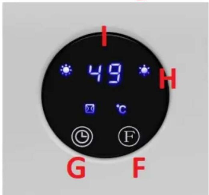
text_image
I 49 H G Fnatural_image
Close-up of a white air conditioner panel showing vent slots and ventilation grilles, with red arrows pointing to the ports (no text or symbols visible)text_image
a b c d e SET f - g OK + h i j k l m n TIME /ON EDIT TIME /OFF UNIPRODOtext_image
F P I II ℃ 8:8 8:8 ⑨ ⑤ Ftext_image
F P I II °C Ftext_image
F P C S Ftext_image
F P I II C ⊗text_image
F I II P °C 08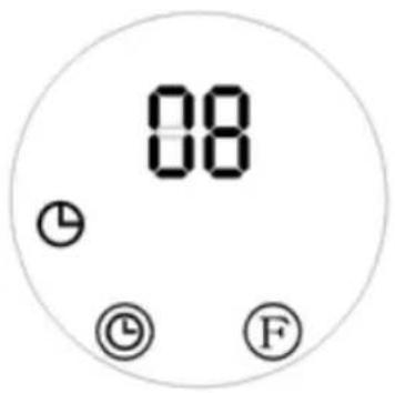
text_image
08 ① © Ftext_image
F I II P ℃ ①