UNI_GPH_04 - Heating Uniprodo - Free user manual and instructions
Find the device manual for free UNI_GPH_04 Uniprodo in PDF.

User questions about UNI_GPH_04 Uniprodo
0 question about this device. Answer the ones you know or ask your own.
Ask a new question about this device
Download the instructions for your Heating in PDF format for free! Find your manual UNI_GPH_04 - Uniprodo and take your electronic device back in hand. On this page are published all the documents necessary for the use of your device. UNI_GPH_04 by Uniprodo.
USER MANUAL UNI_GPH_04 Uniprodo
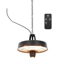
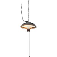
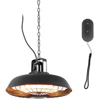
natural_image
Line drawing of a vertical cylindrical device with mesh grille and control panel (no text or symbols)natural_image
Technical illustration of a vertical cylindrical device with mesh structure and labeled component B (no text or symbols beyond label)natural_image
Technical line drawing of a cylindrical industrial device with internal components and an inset close-up view (no text or symbols)natural_image
Technical line drawing of a washing machine component with adjustment knobs and buttons (no text or symbols)natural_image
Technical line drawing of a mechanical component with no visible text or symbolsnatural_image
Technical line drawing of a mechanical assembly with curved components and a central component (no text or symbols)natural_image
Technical diagram of a mechanical device with internal components and an inset view showing a close-up detail (no text or symbols present)natural_image
Line drawing of a washing machine door with adjustment knobs and buttons (no text or symbols)natural_image
Technical line drawing of a mechanical component with no visible text or symbolsnatural_image
Mechanical assembly diagram showing two connected components with curved arrows indicating motion (no text or symbols)SCHALTEN SIE DAS PRODUKT AUS
This User Manual has been translated using machine translation. We have made every effort to ensure the translation is accurate, but please note that automated translations are not perfect and are not meant to replace human translators. The official version of the User Manual is in English. Any differences between the translated version and the original English are not legally binding. If you have any questions about the accuracy of the translation, please refer to the English version, which is the official reference.
Technical data
| Parameter description Parameter value | |||
| Product name Gas patio heater | |||
| Model | UNI_GPH_01 | UNI_GPH_03 | UNI_GPH_04 |
| Heat input [KW] 11 | |||
| Country of destination DE, AT, CH | |||
| Appliance category | I_3B/P(50) | ||
| Type of gas Butane, propane, or their mixtures | |||
| Gas supply pressure [mbar] 50 | |||
| PIN Number 0063BU7882 | |||
| Weight [kg] | 15.2 | 20.4 | 21.3 |
1. General description
The user manual is designed to assist in the safe and trouble-free use of the device. The product is designed and manufactured in accordance with strict technical guidelines, using state-of-the-art technologies and components. Additionally, it is produced in compliance with the most stringent quality standards.
DO NOT USE THE DEVICE UNLESS YOU HAVE THOROUGHLY READ AND UNDERSTOOD THIS USER MANUAL.
To increase the product life of the device and to ensure trouble-free operation, use it in accordance with this user manual and regularly perform maintenance tasks. The technical data and specifications in this user manual are up to date. The manufacturer reserves the right to make changes associated with quality improvement. The device is designed to reduce noise emission risks to a minimum, taking into account technological progress and noise reduction opportunities.
Legend

The product satisfies the relevant safety standards.

Read instructions before use.

WARNING! or CAUTION! or REMEMBER! Applicable to the given situation.
(general warning sign)

WARNING! Toxic substances, danger of poisoning!
Do not touch!
ATTENTION! Hot surface, risk of burns!

PLEASE NOTE! Drawings in this manual are for illustration purposes only and in some details may differ from the actual product.
2. Usage safety

ATTENTION! Read all safety warnings and all instructions. Failure to follow the warnings and instructions may result in serious injury or even death.
The terms "device" or "product" are used in the warnings and instructions to refer to:
Gas patio heater
2.1. Safety in the workplace
a) Make sure the workplace is clean and well lit. A messy or poorly lit workplace may lead to accidents. Try to think ahead, observe what is going on and use common sense when working with the device.
b) Do not use the device in a potentially explosive environment, for example in the presence of flammable liquids, gases or dust. The device generates sparks which may ignite dust or fumes.
c) If you discover damage or irregular operation, immediately switch the device off and report it to a supervisor without delay.
d) If you are unsure about whether the product is operating correctly or if you find damage, please contact the manufacturer's service centre.
e) Only the manufacturer's service centre may make repairs to the product. Do not attempt to make repairs yourself!
f) Use the device in a well-ventilated space.
g) Regularly inspect the condition of the safety labels. If the labels are illegible, they must be replaced.
h) Please keep this manual available for future reference. If this device is passed on to a third party, the manual must be passed on with it.
i) Keep packaging elements and small assembly parts in a place not available to children.
j) Keep the device away from children and animals.
k) If this device is used together with another equipment, the remaining instructions for use shall also be followed.

Remember! Keep children and other bystanders safe while operating the device.
2.2. Personal safety
a) Do not use the device when tired, ill or under the influence of alcohol, narcotics or medication which can significantly impair the ability to operate the device.
b) The device can be handled only by physically fit persons who are capable of handling it, properly trained, familiar with this manual and trained within the scope of occupational health and safety.
c) When working with the device, use common sense and stay alert. Temporary loss of concentration while using the device may lead to serious injuries.
d) The device is not a toy. Children must be supervised to ensure that they do not play with the device.
e) Do not put your hands or other items inside the device while it is in use!
2.3. Safe device use
a) Do not use the device if the "ON/OFF" switch does not function properly (does not switch the device on and off). Devices which cannot be switched on and off using the ON/OFF switch are hazardous, should not be operated and must be repaired.
b) Disconnect the device from the power supply before commencement of adjustment, cleaning and maintenance. Such a preventive measure reduces the risk of accidental activation.
c) When not in use, store in a safe place, away from children and people not familiar with the device who have not read the user manual. The device may pose a hazard in the hands of inexperienced users.
d) Keep the device in perfect technical condition. Before each use check for general damage, especially check moving components for cracked parts or elements, and for any other conditions which may impact the safe operation of the device. If damage is discovered, hand over the device for repair before use.
e) Keep the device out of the reach of children.
f) Device repair or maintenance should be carried out by qualified persons, only using original spare parts. This will ensure safe use.
g) To ensure the operational integrity of the device, do not remove factory-fitted guards and do not loosen any screws.
h) When transporting and handling the device between the warehouse and the destination, observe the occupational health and safety principles for manual transport operations which apply in the country where the device will be used.
i) Do not move, adjust or rotate the device in the course of work.
j) Do not leave this appliance unattended while it is in use.
k) Clean the device regularly to prevent stubborn grime from accumulating.
I) Before each use ensure the nozzle is correctly installed in the device and that the hose is correctly attached and undamaged.
m) Do not exceed the recommended supply pressure as this may damage the device.
n) The device is not a toy. Cleaning and maintenance may not be carried out by children without supervision by an adult person.
o) It is forbidden to interfere with the structure of the device to change its parameters or construction.
p) Keep the device away from sources of fire and heat.
q) Do not exceed the maximum permissible operating pressure!
r) Do not cover the ventilation openings!
s) NOTE: During operation, some elements of the device become very hot – scalding hazard!
t) The maximum permissible pressure of the gas supply to the appliance must not be exceeded! Use only a gas supply with a pressure regulator and suitable nozzles.

ATTENTION! Despite the safe design of the device and its protective features, and despite the use of additional elements protecting the operator, there is still a slight risk of accident or injury when using the device. Stay alert and use common sense when using the device.
3. Use guidelines
natural_image
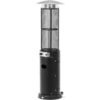
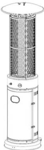
Line drawing of a portable air conditioner with mesh grille and control panel (no text or symbols)The product is designed for professional use in large outdoor spaces, providing effective heating during cold weather. It ensures a comfortable environment for guests in areas such as restaurant terraces or market stalls. The product can be moved to the desired location using its built-in rollers, making it a practical solution for maintaining warmth in outdoor settings.
The user is liable for any damage resulting from unintended use of the device.
3.1. Preparing for use
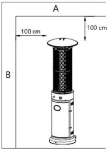
APPLIANCE LOCATION

A- Ceiling
B- Wall
a) The product is primarily for outdoor use only. Always ensure that adequate fresh air ventilation is provided.
b) Always maintain proper clearance of non-protected combustible materials.
i.e. top 100 cm and sides 100 cm minimum.
c) The product must be placed on level firm ground.
d) Never operate the product in explosive environments, such as areas where gasoline or other flammable liquids or vapours are stored.
e) To protect the product from strong winds, securely anchor the base to the ground using screws.
GAS REQUIREMENTS
a) Use only propane, butane, or a mixture of these gases.
b) The pressure regulator and hose assembly used must comply with local standard regulations.
c) Installation must adhere to local codes, or in the absence of such codes, follow standards for the storage and handling of liquefied petroleum gases.
d) A tank that is dented, rusted, or damaged may pose a hazard and should be inspected by your tank supplier. Never use a tank with a damaged valve connection.
e) The tank must be positioned to allow vapour withdrawal from the operating cylinder.
f) Never connect an unregulated tank to the heater.
LEAKAGE TEST
Gas connections on the heater are tested for leaks at the factory before shipment. However, a full gas tightness check must be conducted at the installation site due to potential mishandling during shipment or exposure to excessive pressure.
a) Prepare a soap solution by mixing equal parts of liquid detergent and water. Apply the solution using a spray bottle, brush, or rag. If there is a gas leak, soap bubbles will form at the connection points.
b) Perform the leak test using a full gas cylinder.
c) Ensure the safety control valve is set to the OFF position.
d) Turn the gas supply ON.
f) Never conduct a leak test while smoking.
e) In case of a leak, turn off the gas supply immediately. Tighten the leaking fittings, turn the gas supply on, and recheck for leaks.
Disassemble the device and all its components and clean them before the first use.
3.2. Assembly
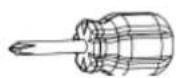
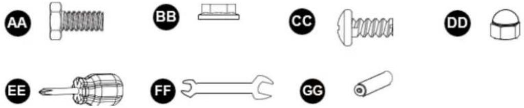
TOOLS NEEDED
a) Medium-blade Phillips screwdriver
b) Spray bottle of soap solution for leak testing
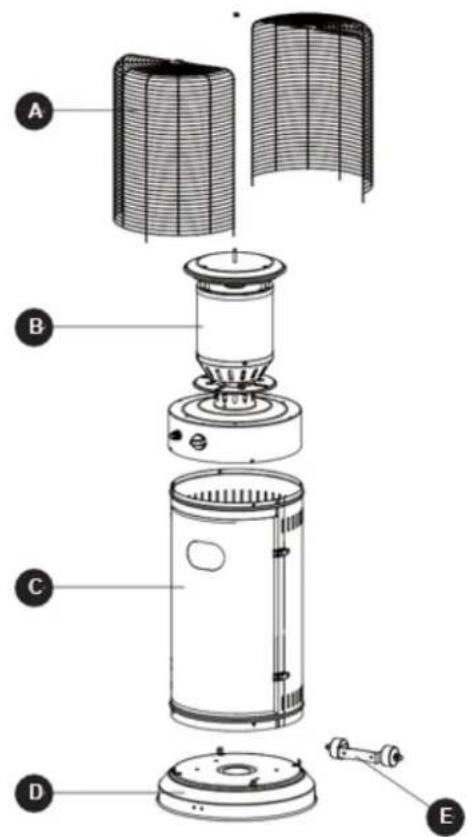
UNI_GPH_03 & UNI_GPH_04
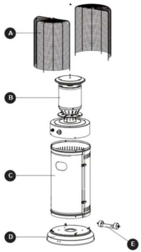
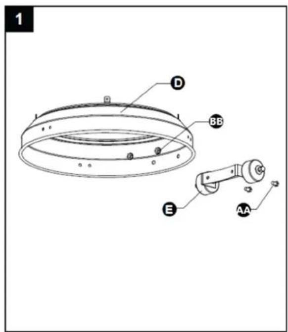
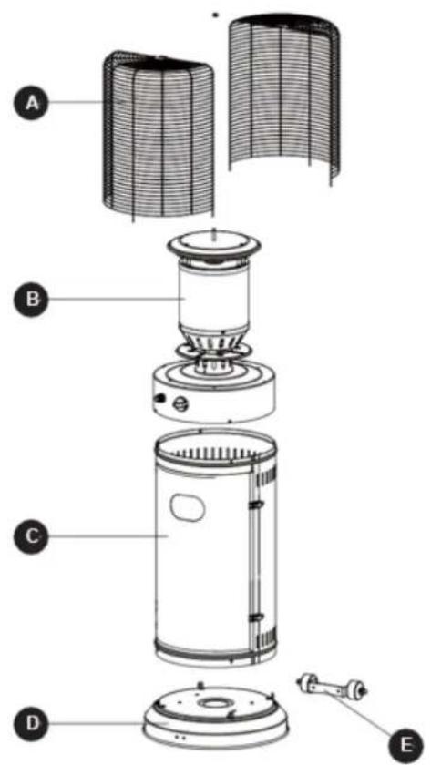
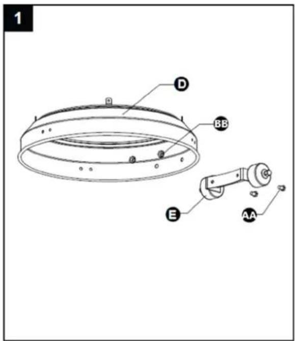
PARTS DIAGRAM
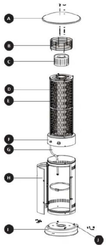
| Part number Description Quantity | ||
| A | Reflector | |
| B Upper Protective Mesh 1 | ||
| C | Mesh | |
| D Rhombic Protective Mesh 1 | ||
| E | Heating | Body |
| F | Control | Box |
| G | Gas | Hose |
| H | Cylinder | Housing |
| I | Base | |
| J | Wheel | |
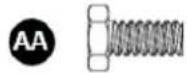
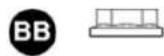
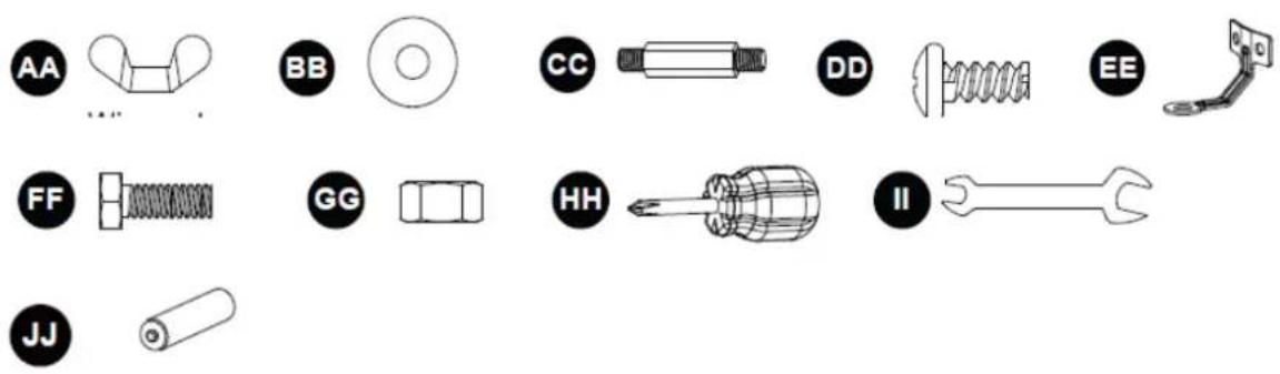
HARDWARE CONTENTS
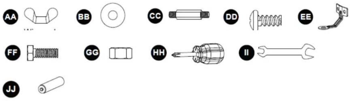
| Number | Description | |
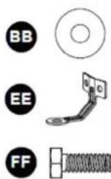
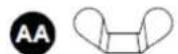
| AA | Wing | nut |
| BB | Washer | 6 |
| CC | Stud | |
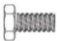
| DD | Screw M5 * 10 | 11 |
| EE | Ground Fixer | 3 |
| FF | Bolt M6 * 10 | 6 |
| GG | Nut M6 | 6 |
| HH | Philips screwdriver | 1 |
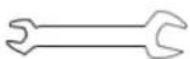
| II | Wrench | |
| JJ | AAA Battery (1.5 V) | 1 |
ASSEMBLY PROCEDURES
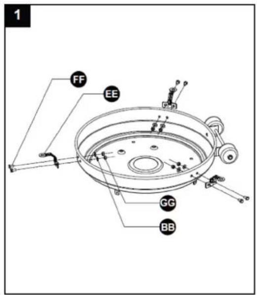
- To protect the product from strong winds, securely anchor the base to the ground using screws. Flip the base over and attach the ground anchor to the base using the M6 * 10 bolt and the washer 6 as shown in the diagram. Secure the ground anchor with the nut M6. Repeat the process for the remaining two ground anchors, then return the base to its upright position.
Hardware Used
Washer 6^*6
Ground Fixer*3
Bolt M6 * 10*6


Nut M6*6

Wrench*1
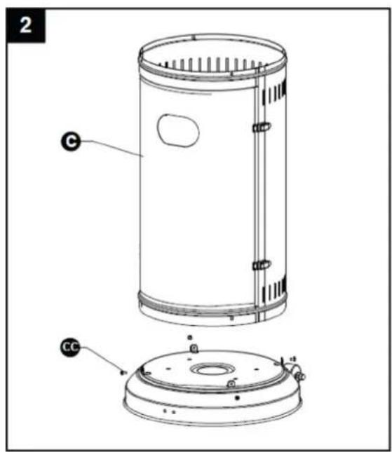
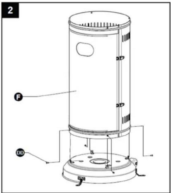
- Assemble the cylinder housing.
Secure the cylinder housing to the base using 4pcs screw M5 * 10.
Hardware Used

Screw M5 * 10*4

Philips screwdriver*1

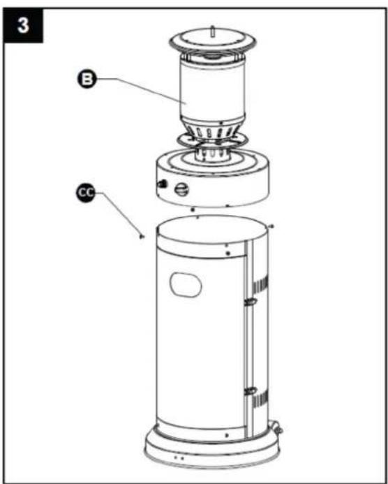
- Assemble the heating body.
Secure the heating body to the cylinder housing using 4pcs screw M5 * 10.
Hardware Used

Screw M5 * 10*4

Philips screwdriver*1
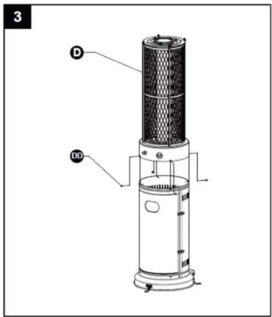
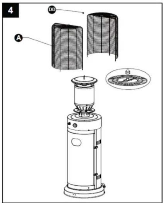
- Assemble the mesh.
Secure the mesh to the heating body using 3pcs screw M5 * 10.
Hardware Used

Screw M5 * 10*3

Philips screwdriver*1
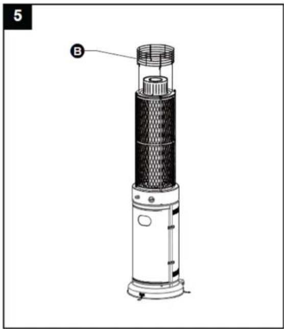
- Assemble the upper protective mesh to the heating body directly.

CAUTION! Do not hang clothing or any other flammable materials from the product or place ear the product. HOT! DO NOT TOUCH!
natural_image
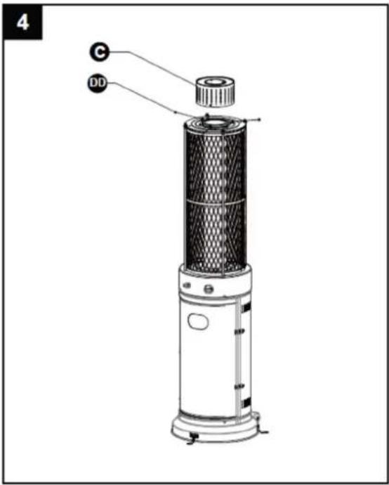
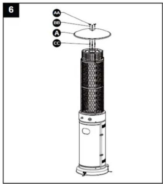
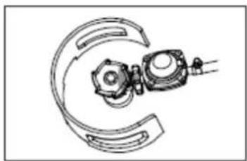
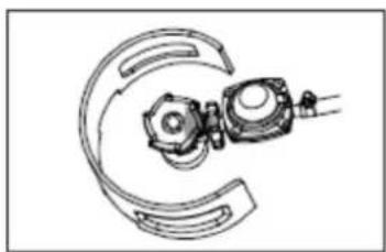
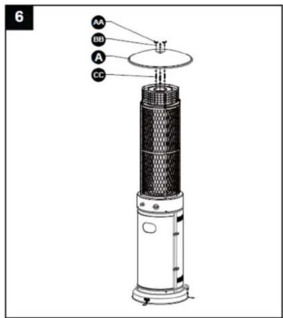
Technical line drawing of a vertical cylindrical device with mesh structure and labeled component B (no text or symbols beyond label)- Assemble the reflector.
a) Screw 3pcs stud to the top of the mesh, using 3pcs washer 6 to the bottom and 3pcs washer 6 to the top.
b) Put the reflector on the stud and secure them using 3pcs wing nut and 3pcs washer.
Hardware Used

Wing nut*3


Washer Φ6*9

Stud*3
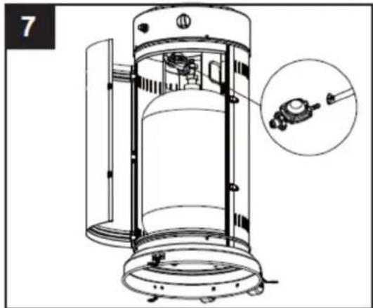
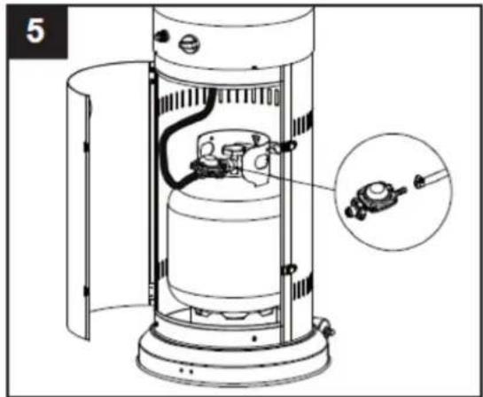
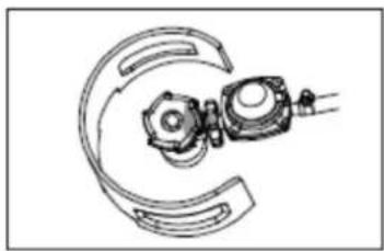
- Connect the gas hose and regulator after that connect the regulator to the gas cylinder.

WARNING! Ensure the hose does not contact any high-temperature surfaces, as this could not to melt and leak, potentially leading to a fire.
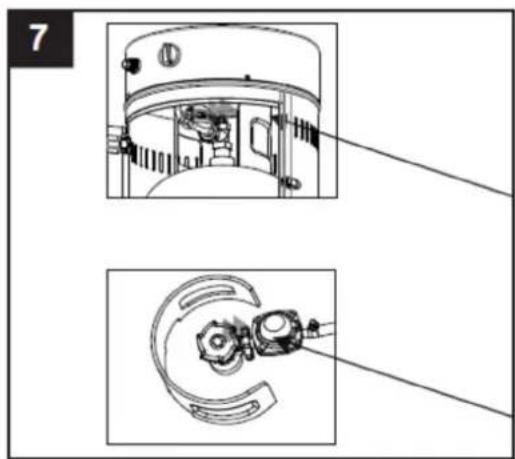
Once the cylinder is positioned inside the heater, securely fasten it with a strap or block belt.
natural_image
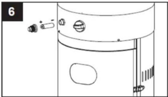
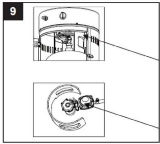
Technical line drawing of a cylindrical industrial vessel with internal components and an inset showing a mechanical component (no text or symbols)- Unscrew the switch button, load a small battery, and tighten the switch button.
Hardware Used


AAA Battery (1.5 V) *1

natural_image
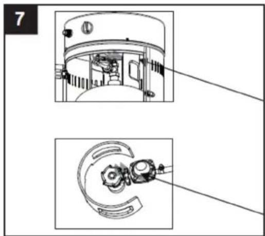
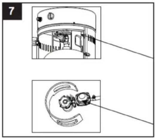
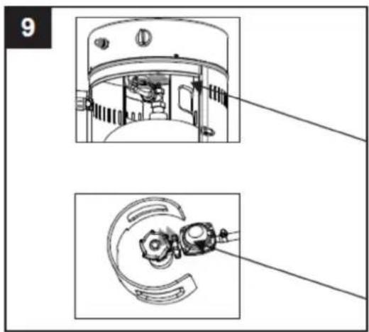
Line drawing of a washing machine component with adjustment knobs and buttons (no text or symbols)- Leak check.
This procedure must be completed before the initial use, annually, and any time gas components are replaced or serviced. Do not smoke during this test and remove all ignition sources. Refer to the below diagram for areas to inspect. Turn all burner controls to the off position and open the gas supply valve. Apply a solution of equal parts liquid soap and water to all joints and connections, including the regulator, hose, manifolds, and valves.
If bubbles appear, it indicates a gas leak. Tighten any loose joints or replace faulty parts. Have the product inspected by a certified gas installer.
If the leak persists, immediately turn off the gas supply, disconnect it, and have the product inspected by a certified gas installer or dealer. Do not operate the product until the leak is fully resolved.

WARNING!
- A leak test must be performed annually and each time a cylinder is hooked up or if a part of the gas system is replaced.
- Never use an open flame to check for gas leaks. Be certain no sparks or open flames are in the area while you check for leaks. Sparks or open flames will result in a fire or explosion, damage to property, serious bodily injury, or death.
natural_image
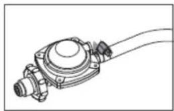
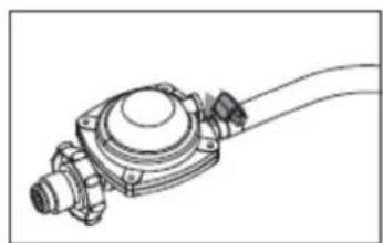
Technical line drawing of a mechanical component with no visible text or symbolsHose / Regulator connection
natural_image
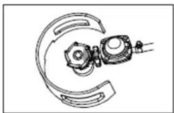
Mechanical assembly diagram showing two components connected by curved lines (no text or labels)Regulator / Cylinder connection

UNI_GPH_01
PARTS DIAGRAM
| Part number Description Quantity | ||
| A Flame screen guard 1 | ||
| B | Burner | assembly |
| C | Cylinder | Housing |
| D | Base | |
| E | Wheel | |
HARDWARE CONTENTS


| Number | Description | |
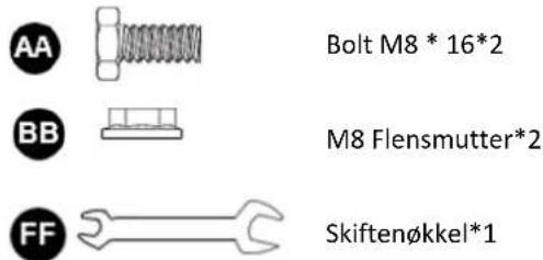
| AA Bolt M8 * 16 | 2 | |
| BB M8 Flange nut | 2 | |
| CC Screw M5 * 8 | 8 | |
| DD M6 Dome nut | 1 | |
| EE | Philips screwdriver | 1 |
| FF | Wrench | 1 |
| GG | AAA Battery (1.5 V) | 1 |
Quantity
ASSEMBLY PROCEDURES
- Use 2pcs Bolt M8 * 16 and M8 Flange nuts to connect the bracket with the wheel to the base.
Hardware Used
Bolt M8 * 16*2
M8 Flange nut*2

Wrench*1
- Use 4pcs screw M5 * 8 to join the cylinder housing base and stand.
Hardware Used

Screw M5 * 8*4
Philips screwdriver*1
- Use 4pcs screw M5 * 8 to join the burner head and cylinder housing body.
Hardware Used

Screw M5 * 8*4

Philips screwdriver*1
- Use the M6 Dome nut to connect the two half safety guards to the burner head.

CAUTION! Do not hang clothing or any other flammable materials from the product or place ear the product. HOT! DO NOT TOUCH!
Hardware Used


M6 Dome nut*1
- Propane only proper hose connection.

WARNING! Ensure the hose does not contact any high-temperature surfaces, as this could not to melt and leak, potentially leading to a fire.
Once the cylinder is positioned inside the heater, securely fasten it with a strap or block belt.
The heater must be fixed on a stable and strong table with a minimum height of 40cm from the floor level.
natural_image
Technical diagram of a mechanical device with internal components and an inset view showing a close-up detail (no text or symbols present)- Unscrew the switch button, load a small battery, and tighten the switch button.
Hardware Used


AAA Battery (1.5 V) *1
natural_image
Line drawing of a washing machine front panel with adjustment knobs and buttons (no text or symbols)- Leak check.
This procedure must be completed before the initial use, annually, and any time gas components are replaced or serviced. Do not smoke during this test and remove all ignition sources. Refer to the below diagram for areas to inspect. Turn all burner controls to the off position and open the gas supply valve. Apply a solution of equal parts liquid soap and water to all joints and connections, including the regulator, hose, manifolds, and valves.
If bubbles appear, it indicates a gas leak. Tighten any loose joints or replace faulty parts. Have the product inspected by a certified gas installer.
If the leak persists, immediately turn off the gas supply, disconnect it, and have the product inspected by a certified gas installer or dealer. Do not operate the product until the leak is fully resolved.

WARNING!
- A leak test must be performed annually and each time a cylinder is hooked up or if a part of the gas system is replaced.
- Never use an open flame to check for gas leaks. Be certain no sparks or open flames are in the area while you check for leaks. Sparks or open flames will result in a fire or explosion, damage to property, serious bodily injury, or death.
natural_image
Technical line drawing of a mechanical component with no visible text or symbolsHose / Regulator connection
natural_image
Technical line drawing of a mechanical assembly with curved components and a central component (no text or symbols)Regulator / Cylinder connection
3.3. Operation
TURN ON THE PRODUCT
a) Turn on the valve on the gas supply cylinder completely.
b) Press and turn the variable control knob to the PILOT position (counterclockwise 90°).
c) Press down the variable control knob and hold for 60 seconds. While holding down the variable control knob, press the igniter button several times until the pilot flame lights. Release the variable control knob after the pilot flame lights.

NOTICE!
- If a new tank has just been connected, please allow at least one minute for the air in the gas pipeline to purge out through the pilot hole.
- When lighting the pilot flame make sure that the variable control knob is continuously pressed down while pressing the igniter button. Variable control knob can be released after the pilot flame lights.
• If the pilot flame does not light or it goes out, repeat step c) mentioned above.
d) After the pilot flame lights, turn the variable control knob to the maximum position and leave it there for 5 minutes or more before turning the knob to desired temperature position.

WARNING! Check and ensure that no broken on the glass is found before operation.
TURN OFF THE PRODUCT
a) Turn the variable control knob to the PILOT position.
b) Press and turn the variable control knob to the OFF position.
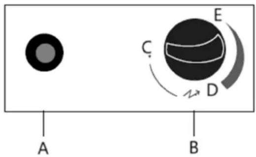
A- Igniter
B- PILOT: Variable control knob
C- OFF: The heater stop work
D- HIGH: Maximum temperature position
E- LOW: Minimum temperature position
c) Turn off the valve on the gas supply cylinder completely.
3.4. Storage
a) Always close the gas cylinder valve after use or if there is any disturbance.
b) Remove the pressure regulator and hose after shutting off the gas supply.
c) Inspect the gas valve for tightness and check for any signs of damage. If damage is suspected, have the valve replaced by your gas supplier.
d) Never store liquid gas cylinders in underground areas or locations without proper ventilation.
3.5. Cleaning and maintenance
a) Clean powder-coated surfaces using a soft, damp cloth. Avoid using combustible or corrosive cleaners on the product.
b) Regularly remove debris from the burner to ensure it remains clean and safe for operation.
c) When the product is not in use, cover the burner unit with an optional protective cover for added protection.
SAFE REMOVAL OF BATTERIES AND RECHARGEABLE BATTERIES
1.5V AAA batteries are installed in the devices.
Remove used batteries from the device using the same procedure by which you installed them.
Recycle batteries with the appropriate organization or company.
DISPOSING OF USED DEVICES
Do not dispose of this device in municipal waste systems. Hand it over to an electric and electrical device recycling and collection point. Check the symbol on the product, instruction manual, and packaging. The plastics used to construct the device can be recycled in accordance with their markings. By choosing to recycle you are making a significant contribution to the protection of our environment.
Contact local authorities for information on your local recycling facility.
3.6. Troubleshooting
| Problem | Possible | cause |
| The pilot will not light | a) The gas valve may be OFF | a) Turn the gas valve ON |
| b) Tank fuel empty | b) Refill LPG tank | |
| c) Opening blocked | c) Clean or replace the opening | |
| d) Air in the supply system | d) Purge air from lines | |
| e) Loose connections | e) Check all fittings | |
| The pilot will not stay on | a) Debris around the pilot | a) Clean dirty area |
| b) Loose connections | b) Tighten connections | |
| c) Thermocouple fail | c) Replace thermocouple | |
| d) Gas leak in line | d) Check connections | |
| e) Lack of fuel pressure | e) The tank is nearly empty. Refill LPG tank | |
| The burner will not light | a) Pressure is low | a) The tank is nearly empty. Refill LPG tank |
| b) Opening blocked | b) Remove and clean | |
| c) Control not ON | c) Turn the valve to ON | |
| d) Thermocouple fail | d) Replace thermocouple | |
| e) The pilot light assembly bent | e) Place the pilot properly | |
| f) Not in the correct location | f) Position properly and retry |

natural_image
Line drawing of a portable air conditioner with mesh grille and control panel (no text or symbols)natural_image
Technical illustration of a vertical cylindrical device with mesh structure and labeled component B (no text or symbols beyond label)- Złóż reflektor.
natural_image
Technical line drawing of a cylindrical device with internal components and an inset close-up view (no text or symbols)natural_image
Technical line drawing of a washing machine component with adjustment knobs and buttons (no text or symbols)natural_image
Technical line drawing of a mechanical component with no visible text or symbolsnatural_image
Mechanical assembly diagram showing two components connected by curved lines (no text or labels)natural_image
Technical diagram of a mechanical device with internal components and an inset view showing a close-up detail (no text or symbols present)natural_image
Line drawing of a washing machine door with adjustment knobs and buttons (no text or symbols)natural_image
Technical line drawing of a mechanical component with no visible text or symbolsnatural_image
Mechanical assembly diagram showing two components with curved and straight lines, no visible text or symbolsnatural_image
Line drawing of a vertical cylindrical device with mesh grille and control panel (no text or symbols)natural_image
Technical line drawing of a vertical cylindrical device with internal mesh structure and labeled component B (no text or symbols beyond label)- Sestavte reflektor.
natural_image
Technical line drawing of a cylindrical industrial vessel with internal components and an inset close-up showing a mechanical component (no text or symbols)natural_image
Line drawing of a washing machine component with adjustment knobs and buttons (no text or symbols)natural_image
Technical line drawing of a mechanical component with no visible text or symbolsnatural_image
Mechanical assembly diagram showing a gear and housing components (no text or labels)natural_image
Technical diagram of a cylindrical device with internal components and an inset showing a close-up view of a small component (no text or symbols present)natural_image
Technical line drawing of a washing machine component with adjustment knobs and buttons (no text or symbols)- Kontrola těsnosti.
natural_image
Technical line drawing of a mechanical component with no visible text or symbolsnatural_image
Technical line drawing of a mechanical component with curved and straight lines (no text or symbols)natural_image
Line drawing of a vertical cylindrical device with mesh grille and control panel (no text or symbols)natural_image
Technical illustration of a vertical cylindrical device with mesh structure and labeled component B (no text or symbols beyond label)natural_image
Technical line drawing of a cylindrical industrial device with internal components and an inset close-up view (no text or symbols)natural_image
Technical line drawing of a washing machine component with adjustment knobs and buttons (no text or symbols)natural_image
Technical line drawing of a mechanical component with no visible text or symbolsnatural_image
Technical line drawing of a mechanical assembly with curved components and a central housing (no text or symbols)natural_image
Technical diagram of a mechanical device with internal components and an inset view showing a close-up detail (no text or symbols)natural_image
Line drawing of a washing machine door with adjustment knobs and buttons (no text or symbols)natural_image
Technical line drawing of a mechanical component with no visible text or symbolsnatural_image
Technical line drawing of a mechanical device with no visible text or symbolsnatural_image
Line drawing of a portable air conditioner with mesh grille and control panel (no text or symbols)natural_image
Technical line drawing of a vertical cylindrical device with internal mesh structure and labeled component B (no text or symbols beyond label)natural_image
Technical line drawing of a cylindrical industrial device with internal components and an inset close-up view (no text or symbols)natural_image
Technical line drawing of a washing machine component with adjustment knobs and buttons (no text or symbols)- Controllo perdite.
natural_image
Technical line drawing of a mechanical component with no visible text or symbolsnatural_image
Technical line drawing of a mechanical component with curved and straight lines (no text or symbols)natural_image
Technical diagram of a mechanical device with internal components and an inset view showing a close-up detail (no text or symbols present)natural_image
Line drawing of a washing machine door with adjustment knobs and buttons (no text or symbols)- Controllo perdite.
natural_image
Technical line drawing of a mechanical component with no visible text or symbolsnatural_image
Technical line drawing of a mechanical component with curved and straight sections (no text or symbols)natural_image
Line drawing of a vertical cylindrical device with mesh grille and control panel (no text or symbols)natural_image
Technical illustration of a vertical cylindrical device with mesh structure and labeled component B (no text or symbols beyond label)natural_image
Technical line drawing of a cylindrical industrial device with internal components and an inset close-up view (no text or symbols)natural_image
Technical line drawing of a washing machine component with adjustment knobs and buttons (no text or symbols)natural_image
Technical line drawing of a mechanical component with no visible text or symbolsnatural_image
Technical line drawing of a mechanical component with curved and straight lines (no text or symbols)natural_image
Technical line drawing of a cylindrical device with internal components and an inset showing a close-up of a small component (no text or symbols present)natural_image
Line drawing of a washing machine door with adjustment knobs and buttons (no text or symbols)natural_image
Technical line drawing of a mechanical component with no visible text or symbolsnatural_image
Technical line drawing of a mechanical component with curved and straight lines (no text or symbols)natural_image
Line drawing of a vertical cylindrical device with mesh grille and control panel (no text or symbols)natural_image
Technical illustration of a vertical cylindrical device with mesh structure and labeled component B (no text or symbols beyond label)natural_image
Technical line drawing of a cylindrical device with internal components and an inset close-up view (no text or symbols)natural_image
Line drawing of a washing machine door with adjustment knobs and buttons (no text or symbols)natural_image
Technical line drawing of a mechanical component with no visible text or symbolsnatural_image
Technical line drawing of a mechanical assembly with curved components and a central component (no text or symbols)natural_image
Technical diagram of a mechanical device with internal components and an inset view showing a close-up detail (no text or symbols)natural_image
Line drawing of a washing machine door with adjustment knobs and buttons (no text or symbols)natural_image
Technical line drawing of a mechanical component with no visible text or symbolsnatural_image
Technical line drawing of a mechanical assembly with curved components and a central component (no text or symbols)OBS! Giftige stoffer, fare for forgiftning!

natural_image
Line drawing of a vertical cylindrical device with mesh grille and control panel (no text or symbols)APPARATETS PLACERING

A- Loft
B- Væg
natural_image
Technical line drawing of a vertical cylindrical device with mesh structure and labeled component B (no text or symbols beyond label)- Saml reflektoren.
- Tilslut gasslangen og regulatoren, og tilslut derefter regulatoren til gasflasken.

natural_image
Technical line drawing of a cylindrical industrial vessel with internal components and an inset showing a mechanical component (no text or symbols)natural_image
Line drawing of a washing machine component with adjustment knobs and buttons (no text or symbols)- Lækagetjek.
natural_image
Technical line drawing of a mechanical component with no visible text or symbolsTilslutning af slange/regulator

natural_image
Technical line drawing of a mechanical assembly with curved components and a central component (no text or symbols)Tilslutning af regulator/cylinder

UNI_GPH_01
PARTS DIAGRAM
natural_image
Technical diagram of a mechanical device with internal components and an inset view showing a close-up detail (no text or symbols present)natural_image
Line drawing of a washing machine handle with adjustment knobs and buttons (no text or symbols)- Lækagetjek.
natural_image
Technical line drawing of a mechanical component with no visible text or symbolsTilslutning af slange/regulator
natural_image
Technical line drawing of a mechanical assembly with curved components and a central component (no text or symbols)Tilslutning af regulator/cylinder
3.3. Handling
TÆND FOR PRODUKTET
natural_image
Line drawing of a portable air conditioner with mesh grille and control panel (no text or symbols)natural_image
Technical line drawings of screw and nut components (no text or symbols)Ruuvi M5 * 10*4
Philips-ruuvimeisseli*1
- Kokoa lämmitysrunko.
natural_image
Technical line drawing of a vertical cylindrical device with mesh structure and labeled component B (no text or symbols beyond label)- Kokoa heijastin.
natural_image
Technical line drawing of a cylindrical industrial device with internal components and an inset close-up view (no text or symbols)natural_image
Line drawing of a washing machine door with adjustment knobs and buttons (no text or symbols)- Vuototarkistus.
natural_image
Technical line drawing of a mechanical component with no visible text or symbolsnatural_image
Technical line drawing of a mechanical assembly with curved components and a central component (no text or symbols)natural_image
Technical diagram of a mechanical device with internal components and an inset view showing a close-up detail (no text or symbols present)natural_image
Line drawing of a door handle assembly with adjustment knobs and buttons (no text or symbols)- Vuototarkistus.
natural_image
Technical line drawing of a mechanical component with no visible text or symbolsnatural_image
Technical line drawing of a mechanical assembly with curved components and a central component (no text or symbols)natural_image
Line drawing of a vertical cylindrical device with mesh grille and control panel (no text or symbols)PLAATS VAN HET APPARAAT
A- Plafond
B- Muur
natural_image
Technical illustration of a vertical cylindrical device with mesh structure and labeled component B (no text or symbols beyond label)- Monteer de reflector.
natural_image
Technical line drawing of a cylindrical industrial vessel with internal components and an inset close-up showing a mechanical component (no text or symbols)natural_image
Technical line drawing of a washing machine component with adjustment knobs and buttons (no text or symbols)9. Lekcontrole.
natural_image
Technical line drawing of a mechanical component with no visible text or symbolsnatural_image
Technical line drawing of a mechanical component with curved and straight sections (no text or symbols)natural_image
Technical diagram of a cylindrical device with internal components and an inset showing a close-up view of a small component (no text or symbols present)natural_image
Line drawing of a washing machine door with adjustment knobs and buttons (no text or symbols)7. Lekcontrole.
natural_image
Technical line drawing of a mechanical component with no visible text or symbolsnatural_image
Technical line drawing of a mechanical component with curved and straight sections (no text or symbols)SCHAKEL HET PRODUCT UIT
OBS! Varm overflate, fare for forbrenning!

natural_image
Line drawing of a portable air conditioner with mesh grille and control panel (no text or symbols)| Artikkelnummer | Beskrivelse | Antall |
| A | Reflektor | |
| B | ∅vre beskyttelsesnett | |
| C | Mesh | |
| D | Rombisk | beskyttelsesnett |
| E | Varmekropp | |
| F | Kontrollboks | |
| G | Gasslange | |
| H | Sylinderhus | |
| I | Ramme | |
| J | Hjul |
MASKINVAREN INNHOLD
| Tall | Beskrivelse | Antall |
| AA | Vingemutter | |
| BB | Skive | 6 |
| CC | Stud | |
| DD Skrue M5 * 10 11 | ||
| EE | Jordfikser | |
| FF Bolt M6 * 10 6 | ||
| GG | Mutter | M6 |
| HH | Philips skrutrekker | |
| II. | Skiftenøkkel | 1 |
| JJ | AAA-batteri (1,5 V) | 1 |
MONTERINGSPROSEDYRER
natural_image
Technical line drawing of a vertical cylindrical device with internal mesh structure and labeled component B (no text or symbols beyond label)- Sett sammen reflektoren.
a) Skru 3 stk bolt til toppen av nettet, bruk 3 stk skive Φ6 til bunnen og 3 stk skive Φ6 til toppen.
b) Sett reflektoren på tappen og fest dem med 3 stk vingemutter og 3 stk skive.
Maskinvare brukt
Vingemutter*3
Skive 6^*9

Stud*3
- Koble gasslangen og regulatoren deretter koble regulatoren til gassflasken.
natural_image
Technical line drawing of a cylindrical industrial device with internal components and an inset close-up showing a component (no text or symbols)natural_image
Line drawing of a washing machine component with adjustment knobs and buttons (no text or symbols)9. Lekkasjesjekk.
natural_image
Technical line drawing of a mechanical component with no visible text or symbolsSlange / regulator tilkobling

natural_image
Technical line drawing of a mechanical assembly with curved components and a central component (no text or symbols)Regulator / Sylinder tilkobling
UNI_GPH_01
DELEDIAGRAM
| Artikkelnummer | Beskrivelse | Antall |
| A | Flammeskjermvakt | |
| B | Brennermontering | |
| C | Sylinderhus | |
| D | Ramme | |
| E | Hjul |
MASKINVAREN INNHOLD
| Tall | Beskrivelse | Antall |
| AA Bolt M8 * 16 | 2 | |
| BB | M8 | Flensmutter |
| CC Skrue M5 * 8 | 8 | |
| DD | M6 | Kuppelmutter |
| EE | Philips | skrutrekker |
| FF | Skiftenøkkel | |
| GG AAA-batteri (1,5 V) | 1 |
MONTERINGSPROSEDYRER
- Bruk 2 stk Bolt M8 * 16 og M8 flensmuttere for å koble braketten med hjulet til basen.
Maskinvare brukt
natural_image
Technical diagram of a cylindrical device with internal components and an inset close-up view (no text or symbols)natural_image
Line drawing of a washing machine door with adjustment knobs and buttons (no text or symbols)7. Lekkasjesjekk.
natural_image
Technical line drawing of a mechanical component with no visible text or symbolsSlange / regulator tilkobling
natural_image
Technical line drawing of a mechanical component with curved and straight lines (no text or symbols)Regulator / Sylinder tilkobling
3.3. Bruk
SLÅ PÅ PRODUKTET
a) Slå på ventilen på gasstilførselssylinderen helt.
natural_image
Line drawing of a vertical cylindrical device with mesh grille and control panel (no text or symbols)APPARATENS PLACERING

A- Tak
B- Vägg
| Antal | Beskrivning | |
| AA | Vingmutter | |
| BB | Bricka | 6 |
| CC | Hingst | |
| DD Skruv M5 * 10 11 | ||
| EE | Markfixare | |
| FF Bult M6 * 10 6 | ||
| GG | Mutter M6 | 6 |
| HH | Philips skruvmejsel | 1 |
| II | Rycka | |
| JJ | AAA-batteri (1,5 V) | 1 |
MONTERINGSFÖRFARANDEN
natural_image
Technical line drawings of screw and nut components (no text or symbols)Skruv M5 * 10*4
natural_image
Technical line drawing of a vertical cylindrical device with mesh structure and labeled component B (no text or symbols beyond label)natural_image
Technical line drawing of a cylindrical industrial vessel with internal components and an inset showing a mechanical component (no text or symbols)natural_image
Line drawing of a washing machine component with adjustment knobs and buttons (no text or symbols)- Läckagekontroll.
natural_image
Technical line drawing of a mechanical component with no visible text or symbolsnatural_image
Technical line drawing of a mechanical assembly with curved components and no visible text or symbolsRegulator/cylinderanslutning
UNI_GPH_01
DELAR DIAGRAM