UNI_EH_04 - Heating Uniprodo - Free user manual and instructions
Find the device manual for free UNI_EH_04 Uniprodo in PDF.

| Product type | Infrared patio heater |
| Brand | Uniprodo |
| Model | UNI_EH_04 |
| Rated voltage | 230 V / 50 Hz |
| Rated power | 2000 W (3 settings: 650 W, 1300 W, 2000 W) |
| Protection rating | IP34 |
| Dimensions (L x D x H) | 900 x 600 x 150 mm |
| Weight | 3.61 kg |
| Heating element type | Halogen |
| Number of heat settings | 3 |
| Remote control included | Yes |
| Tilt safety switch | Yes |
| Minimum installation height | 1.8 m |
| Clearance from roof | 30 cm |
| Outdoor use | Yes (rain-resistant, do not use in the rain) |
| Cleaning method | Damp cloth, solvent-free |
| Repairs | By qualified electrician |
| Maintenance | Unplug before cleaning, never immerse |
Frequently Asked Questions - UNI_EH_04 Uniprodo
User questions about UNI_EH_04 Uniprodo
0 question about this device. Answer the ones you know or ask your own.
Ask a new question about this device
Download the instructions for your Heating in PDF format for free! Find your manual UNI_EH_04 - Uniprodo and take your electronic device back in hand. On this page are published all the documents necessary for the use of your device. UNI_EH_04 by Uniprodo.
USER MANUAL UNI_EH_04 Uniprodo
natural_image
Technical line drawing of a mechanical component with a star symbol and curved arrow indicating rotation (no text or labels)natural_image
Technical line drawing of a mechanical device mounted on a vertical pole, showing internal components and alignment lines (no text or symbols)
natural_image
Technical line drawing of a mechanical assembly with no visible text or symbolsThis User Manual has been translated for your convenience using machine translation. Reasonable efforts have been made to provide an accurate translation; however, no automated translation is perfect nor is it intended to replace human translators. The official User Manual is the English version. Any discrepancies or differences created in the translation are not binding and have no legal effect for compliance or enforcement purposes. If any questions arise related to the accuracy of the information contained in the User Manual, please refer to the English version of those contents which is the official version.
Technical data
| Parameter description | Parameter value |
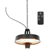
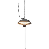
| Product name | Umbrella infrared patio Heater |
| Model | UNI_EH_04 |
| Rated voltage [V~] / Frequency [Hz] | 230 / 50 |
| Rated power [W] | 2000 |
| Protection rating IP | IP34 |
| Dimensions [Width x Depth x Height; mm] | 900 x 600 x 150 |
| Weight [kg] | 3.61 |
Assembly instructions for the halogen heater
1. Unpack the heater
Carefully unpack the halogen heater. Ensure that all components are present and check that nothing is left in the box. Confirm that the heater head is completely free of any packing material.
2. Assemble the heater
Follow the steps provided in the detailed assembly drawing to correctly put together your halogen heater.
3. Before connecting to power
- Do not connect the heater to an electrical supply until assembly is fully complete.
- Do not connect the heater if any components or the power cord are damaged.
Safety precautions for using the electric patio heater
1. Use only on a stable surface
Ensure the electric patio heater is placed on a firm vertical pole with all feet of the pole base in contact with the floor. If the heater tilts or falls over, the automatic cut-off switch will activate.
2. Restricted use
This appliance is not intended for use by individuals (including children) with reduced physical, sensory, or mental capabilities, or lack of experience and knowledge, unless supervised or instructed by someone responsible for their safety.
3. Avoid water hazards
Do not use the heater near bathtubs, wash areas, or swimming pools.
4. Ventilation
Do not operate the heater in unventilated areas.
5. Avoid flammable materials
Do not use the heater in areas where gas, petrol, paint, or other flammable substances are stored.
6. Do not obstruct the heater grill
Never push objects through, obstruct, or cover the grill of the heater head.
7. Positioning of the heater
The heater must not be placed directly below a socket outlet.
8. Handling while powered
Do not move the heater when it is connected to a power supply. Always wait for the heater to cool down before storing it.
9. Touching during operation
Avoid touching the heater head while it is in use as it becomes very hot.
10. Supervision
Never leave the heater turned on and unattended, especially when children or animals are nearby.
11. Minimum clearance requirements
Ensure the heater is placed with a clearance of at least 180 cm to the floor and 30 cm to the roof or parasol cloth.
12. Proper installation
The heater must be installed correctly, at a height of at least 1.8 meters above the floor, and securely placed on a vertically stable pole.
13. Temperature warning
The heater remains hot for a period after being switched off. Be cautious when handling it during this time to avoid burns.
14. Keep away from combustible materials
Do not place the heater near curtains or other flammable materials, as this could lead to a fire hazard.
15. Do not cover the heater
Never cover the heater during operation or immediately after shutdown.
16. Power cord handling
Do not wrap the power cord around the heater unit.
17. Avoid impact or vibration
Handle the unit with care, avoiding vibrations or impacts.
18. Grounding
Ensure the unit is properly grounded during operation.
19. Repair
If the heater is damaged, it must be repaired by a professional service team.
20. Power cord replacement
If the power cord is damaged, it must be replaced by an authorized agent or qualified professional to avoid danger.
21. Assembly clearance
Keep the unit away from boards or flammable materials during assembly.
22. Supervision during use by children
Adults must supervise the heater if used around children.
23. Prohibited installation areas
The heater must not be installed near swimming pools, bathrooms, or shower areas.
24. Cooling before cleaning
The heater head becomes very hot during use. Always unplug the unit and wait for it to cool before cleaning.
25. Avoid corrosive environments
Do not use the heater in areas with corrosive or volatile air (e.g., dust, steam, gas).
- Not for drying purposes
Do not use the heater as a clothes or towel dryer.
- Do not use as a sauna heater
This heater is not designed for sauna use.
- Not a space heater
Do not use the heater for general room heating or heat storage.
- Not for animal care
Do not use the heater in spaces for animal propagation or rearing.
- Not for central heating systems
This unit is not designed for use in hot air central heating systems.
- Do not immerse in water
Never immerse the heater in water for cleaning.
- Accessible power socket
Ensure the unit is plugged into a socket that is easily visible and accessible.
- Initial dark spots
You may notice one or two dark spots on the surface of the heating elements during the first few minutes of operation. This is normal and does not affect the performance.
- Tilt safety switch
The unit is equipped with a tilt switch for safety.
- Supervise children
Ensure children do not play with the appliance.
Assembly instructions for the electric patio heater
Unpack the heater
Carefully unpack the electric patio heater and ensure all components are present.
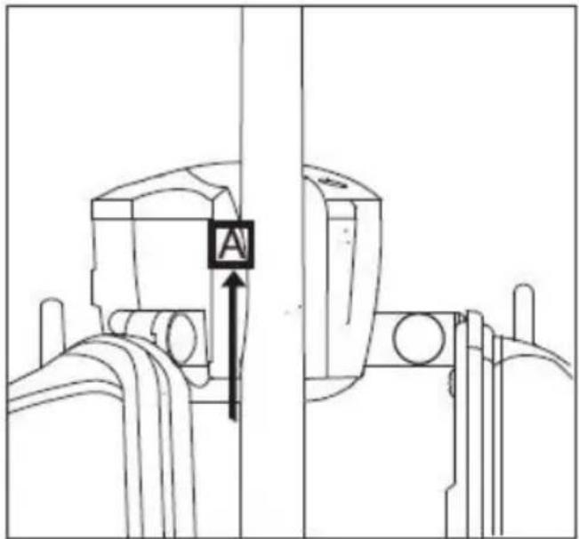
1. Step 1: Attach mounting part A
Place Mounting Part A onto a pole with a diameter between 25 mm and 60 mm.
2. Step 2: Attach mounting part B
Slide Mounting Part B upwards from the bottom of the pole and fit it into Mounting Part A.
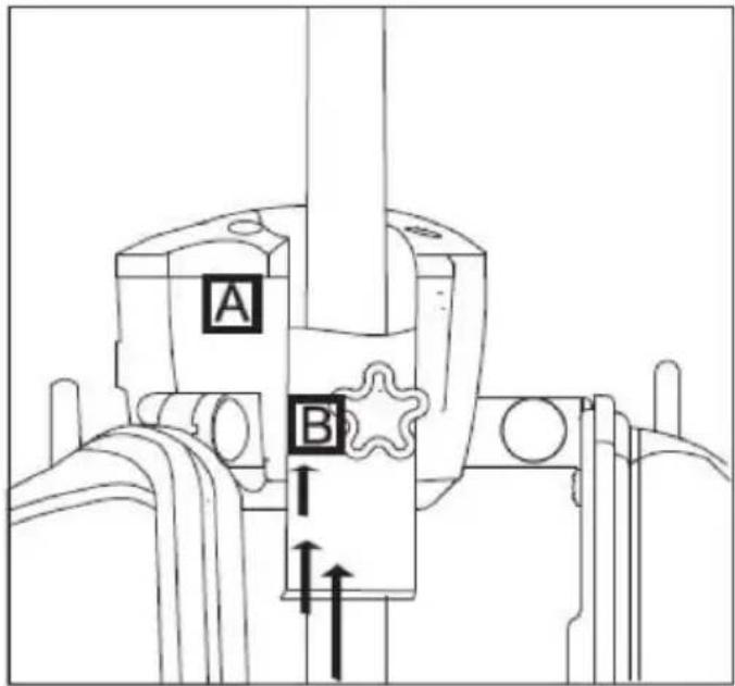
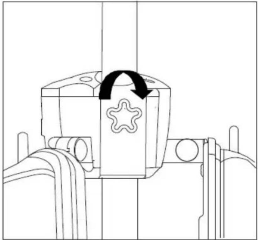
3. Step 3: Secure the mounting parts
Tighten the fixation screw until Mounting Part A is securely fixed to the pole.
natural_image
Technical line drawing of a mechanical component with a star-shaped feature and directional arrow (no text or symbols)4. Step 4: Using the heater
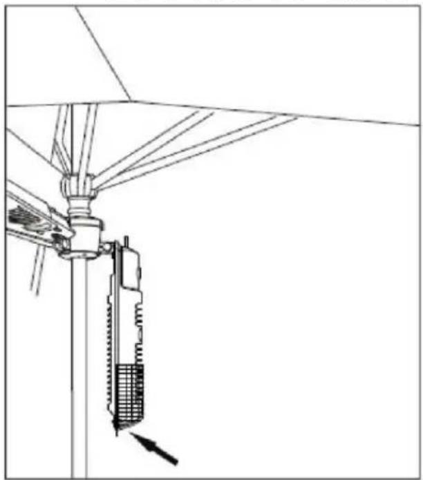
To start using the heater, hold the small handle located at the end of the heater and push the heater upwards.
natural_image
Technical line drawing of a mechanical device mounted on a vertical pole, showing internal components and alignment lines (no text or symbols)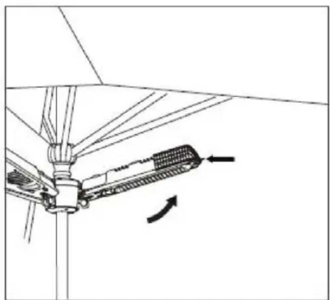
natural_image
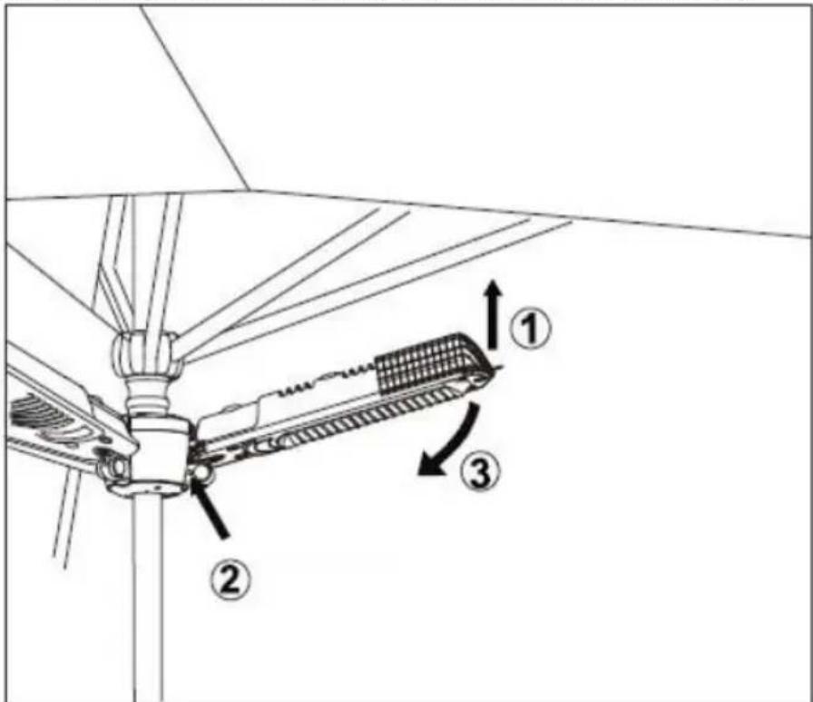
Technical diagram of a mechanical assembly with directional arrows indicating motion or force (no text or symbols)5. Step 5: Turning off and storing the heater
When finished using the heater:
a) Use your right hand to push the heater up (1).
b) With your left hand, press the small silver knob (2) until it reaches the end.
c) Then, use your right hand to gently push the heater down (3).
Operation instructions for the electric patio heater
1. Connect the power cable
Plug the power cable into an electrical supply located in a safe, dry area.
2. Heat settings
Use the switch on the heater head to control the three heat settings:
○ Position (I): 650W
○ Position (II): 1300W
○ Position (I & II): 2000W
○ Position (0): Off
3. Weather precautions
Although the patio heater is shower-proof, do not use it in the rain or under wet conditions.
4. Disconnect when not in use
Always unplug the power cable from the electrical supply when the patio heater is not in use
Care and maintenance
- Cleaning the heater
Before cleaning, disconnect the heater from the electrical supply. Wipe the exterior of the patio heater with a damp cloth. Do not use corrosive or solvent-based cleaners, and never immerse the unit in water.
• Repairs and maintenance
Any repairs or maintenance, including replacing the halogen tube, must be performed by a qualified electrician or a recommended service center.
Storage
If the heater will not be used for an extended period, store it in a cool, dry location. To prevent dust and dirt build-up, repack the heater in its original packaging.
Troubleshooting
If the heater does not operate, check the following before seeking repair or service:
- Ensure the power cord is plugged into an electrical outlet. If not, plug it in.
- Check if electricity is being supplied to the main fuse.
- Confirm the power switches are turned on and that a heat setting is selected.
natural_image
Technical line drawing of a mechanical component with an arrow indicating rotation (no text or symbols)natural_image
Technical line drawing of a mechanical assembly with no visible text or symbols
natural_image
Technical line drawing of a mechanical assembly with no visible text or symbolsnatural_image
Technical line drawing of a mechanical component with an arrow indicating rotation (no text or symbols)natural_image
Technical line drawing of a mechanical device mounted on a vertical pole, showing internal components and alignment lines (no text or symbols)
natural_image
Technical line drawing of a mechanical assembly with no visible text or symbolsnatural_image
Technical line drawing of a mechanical component with an arrow indicating rotation (no text or symbols)natural_image
Technical line drawing of a mechanical device mounted on a vertical pole, showing internal components and wiring (no text or symbols)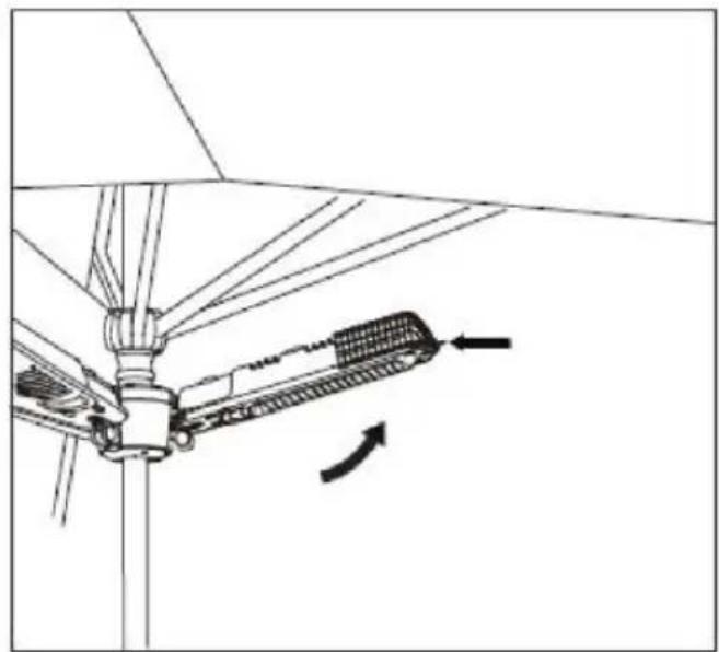
natural_image
Technical line drawing of a mechanical assembly with no visible text or symbolsnatural_image
Technical line drawing of a mechanical component with an arrow indicating rotation (no text or symbols)natural_image
Technical line drawing of a mechanical device mounted on a vertical pole, showing internal components and alignment lines (no text or symbols)
natural_image
Technical line drawing of a mechanical assembly with no visible text or symbolsnatural_image
Technical line drawing of a mechanical component with an arrow indicating rotation (no text or symbols)natural_image
Technical line drawing of a mechanical device mounted on a vertical pole, showing internal components and alignment lines (no text or symbols)
natural_image
Technical line drawing of a mechanical assembly with no visible text or symbolsnatural_image
Technical line drawing of a mechanical component with a star symbol and curved arrow indicating rotation (no text or labels)natural_image
Technical line drawing of a mechanical device mounted on a vertical pole, showing internal components and alignment lines (no text or symbols)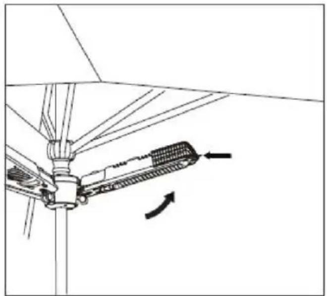
natural_image
Technical line drawing of a mechanical assembly with no visible text or symbolsnatural_image
Technical line drawing of a mechanical component with a circular arrow indicating rotation (no text or symbols)natural_image
Technical line drawing of a mechanical device mounted on a vertical pole, showing internal components and wiring (no text or symbols)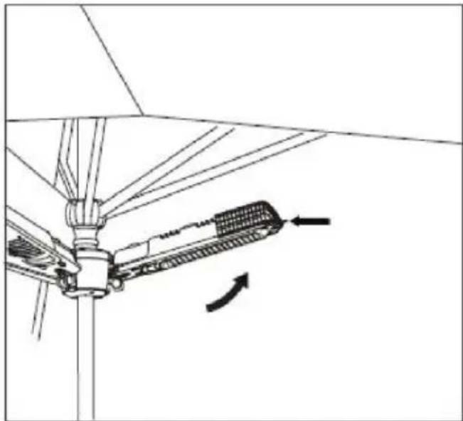
natural_image
Technical line drawing of a mechanical assembly with no visible text or symbolsBruksanvisning for elektrisk terrassevarmer
9. Beröring under drift
natural_image
Technical line drawing of a mechanical component with a star-shaped feature and directional arrow (no text or symbols)natural_image
Technical line drawing of a mechanical assembly with no visible text or symbols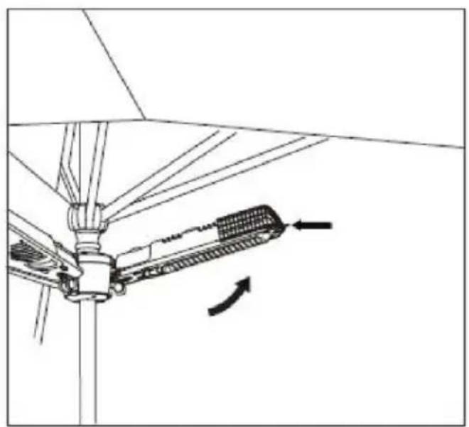
natural_image
Technical diagram of a mechanical assembly with directional arrows indicating motion or force (no text or symbols)natural_image
Technical line drawing of a mechanical component with an arrow indicating rotation (no text or symbols)natural_image
Technical line drawing of a mechanical assembly with no visible text or symbols
natural_image
Technical line drawing of a mechanical assembly with no visible text or symbolsnatural_image
Technical line drawing of a mechanical component with a star-shaped feature and curved arrow indicating rotation (no text or symbols)4. Krok 4: Použitie ohrievača
natural_image
Technical line drawing of a mechanical device mounted on a vertical pole, showing internal components and alignment lines (no text or symbols)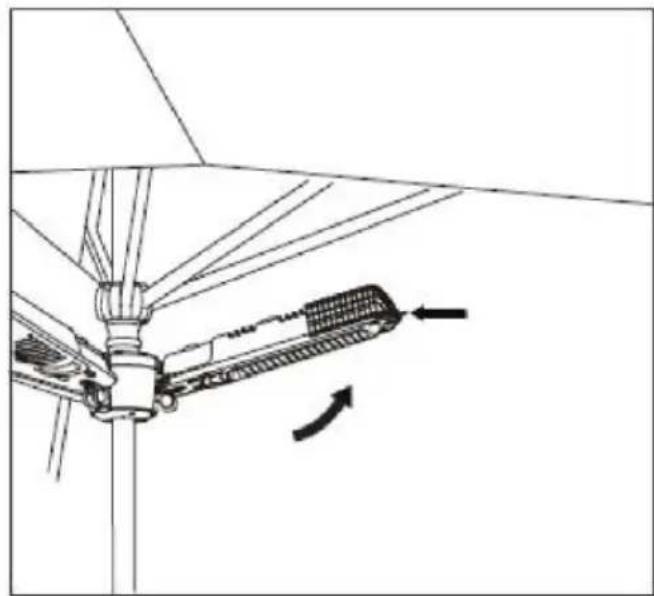
natural_image
Technical diagram of a mechanical assembly with directional arrows indicating motion (no text or symbols)5. Krok 5: Vypnutie a uloženie ohrievača
natural_image
Technical line drawing of a mechanical component with an arrow indicating rotation (no text or symbols)natural_image
Technical line drawing of a mechanical device mounted on a vertical pole, showing internal components and alignment lines (no text or symbols)
natural_image
Technical line drawing of a mechanical assembly with no visible text or symbolsnatural_image
Technical line drawing of a mechanical component with a star symbol and curved arrow indicating rotation (no text or labels)natural_image
Technical line drawing of a mechanical assembly with no visible text or symbols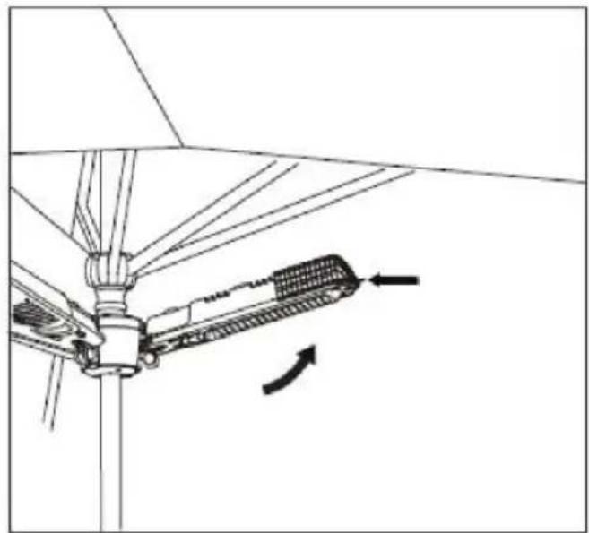
natural_image
Technical diagram of a mechanical assembly with directional arrows indicating motion or force (no text or symbols)natural_image
Technical line drawing of a mechanical component with a star symbol and curved arrow indicating rotation (no text or labels)natural_image
Technical line drawing of a mechanical device mounted on a vertical pole, showing internal components and alignment lines (no text or symbols)
natural_image
Technical line drawing of a mechanical assembly with no visible text or symbolsUpute za rad električne grijalice za terasu
natural_image
Technical line drawing of a mechanical component with an arrow indicating rotation (no text or symbols)natural_image
Technical line drawing of a mechanical device mounted on a vertical pole, showing internal components and alignment lines (no text or symbols)
natural_image
Technical line drawing of a mechanical assembly with no visible text or symbolsnatural_image
Technical line drawing of a mechanical component with a circular arrow indicating rotation (no text or symbols)4. 4. korak: Uporaba grelnika
natural_image
Technical line drawing of a mechanical device mounted on a vertical pole, showing internal components and wiring (no text or symbols)
natural_image
Technical diagram of a mechanical assembly with directional arrows indicating motion or force (no text or symbols)5. 5. korak: Izklopite in shranite grelec
For the disposal of the device please consider and act according to the national and local rules and regulations.
CONTACT
expondo Polska sp. z o.o. sp. k.