
MPC01 - Battery management system DOMETIC - Free user manual and instructions
Find the device manual for free MPC01 DOMETIC in PDF.

| Brand | Dometic |
| Model | MPC01 |
| Product type | Battery management system |
| Article number | 9102500073 |
| Screen dimensions (L x H x D) | 130 x 115 x 6 mm |
| Mounting frame dimensions (L x H x D) | 150 x 136 x 16 mm |
| Weight | Approx. 300 g (estimated) |
| Input voltage | 8 – 30 V DC |
| Power consumption (active mode) | 150 mA |
| Power consumption (standby mode) | 10 mA |
| Main functions | Monitoring of up to 4 batteries (1 starter + 3 auxiliary), display voltage/current/temperature/capacity, programmable outputs (3), programmable alarm, standby mode, automatic sensor calibration |
| Included accessories | Connection plate with cover, bezel frame, screen, mounting frame, 1 battery sensor (Hella Sensor MCA-HS1), connection cables, screws |
| Optional accessories | Additional battery sensor (ref. 9102500038) |
| Maintenance and cleaning | Protect from moisture and dust; clean with a dry, soft cloth; do not use chemicals |
| Safety | Follow safety instructions: disconnect power before intervention, use cables of sufficient cross-section, avoid humid or explosive environments |
| Spare parts and repairability | Battery sensor available as spare part; no information on user repairability |
| General information | Designed for motorhomes and boats; CE and E13 certified; adjustable operating mode (motorhome/boat) via jumper |
Frequently Asked Questions - MPC01 DOMETIC
User questions about MPC01 DOMETIC
0 question about this device. Answer the ones you know or ask your own.
Ask a new question about this device
Download the instructions for your Battery management system in PDF format for free! Find your manual MPC01 - DOMETIC and take your electronic device back in hand. On this page are published all the documents necessary for the use of your device. MPC01 by DOMETIC.
USER MANUAL MPC01 DOMETIC
Please read this instruction manual carefully before installation and first use, and store it in a safe place. If you pass on the product to another person, hand over this instruction manual along with it.
Contents
1 Explanation of symbols. 7
2 Safety instructions. 8
3 Scope of delivery 9
4 Accessories. 9
5 Intended use 10
6 Technical description 10
7 Connecting and installing MPC01 11
8 Operating the MPC01 14
9 Guarantee 23
10 Disposal. 23
11 Technical data. 24
1 Explanation of symbols

WARNING!
Safety instruction: Failure to observe this instruction can cause fatal or serious injury.

CAUTION!
Safety instruction: Failure to observe this instruction can lead to injury.

NOTICE!
Failure to observe this instruction can cause material damage and impair the function of the product.

NOTE
Supplementary information for operating the product.
2 Safety instructions
The manufacturer accepts no liability for damage in the following cases:
- Damage to the product resulting from mechanical influences and excess voltage
- Alterations to the product without express permission from the manufacturer
- Use for purposes other than those described in the operating manual
Please observe the following basic safety information when using electrical devices to prevent:
Electric shock
Fire hazards
- Injury

WARNING!
- Electrical devices are not toys!
Always keep and use the device out of the reach of children.
- People (including children) whose physical, sensory or mental capacities or whose lack of experience or knowledge prevent them from using this product safely should not use it without the supervision or instruction of a responsible person.
- Only use the device as intended.
- Make sure that the lead has a sufficient cross-section.
- Lay the cables so that they cannot be damaged by the doors or the bonnet. Crushed cables can lead to serious injury.

CAUTION!
- Lay the cables so that they cannot be tripped over or damaged.
-
Do not operate the device
-
In salty, wet or damp environments
- In the vicinity of corrosive fumes
-
In areas where there is a danger of explosions.
-
Always disconnect the power supply when working on the device.
- Please observe that parts of the device may still conduct voltage even if the fuse has blown.
- Do not disconnect any cables when the device is still in use.

NOTICE!
- Use ductwork or cable ducts if it is necessary to lay cables through metal panels or other panels with sharp edges.
- Do not lay the cable so that it is loose or heavily kinked.
- Fasten the cables securely.
- Do not pull on the cables.
3 S C O P E O F D E I
| No. in fig. 1, Quantity Designation | |||||
| 1 | Adapter board and cover | ||||
| 2 | 1 | C | o | v | e |
| 3 | 1 | D | i | s | p |
| 4 | Assembly frame | ||||
| 5 | Battery sensor (MCA-HS1 Hella sensor) | ||||
| 6 | Battery sensor connection cable | ||||
| 7 | Charging unit connection cable | ||||
| 8 | 1 | C | o | n | t |
| 9 | Control cable connected mass (black) | ||||
| 10 | Control cable positive pole (red) | ||||
| 11 | Screws, long | ||||
| 12 | 4 | Screws, short | |||
4 Accessories
Available as accessories (not included in the scope of delivery):
| Designation | Ref. no. |
| Battery sensor, MCA-HS1 Hella sensor | 9102500038 |
MPC01 (ref. no. 9102500073) is a battery management system which allows the battery charge status of several batteries to be monitored. MPC01 may only be operated with PerfectCharge MCA chargers.
The device is designed for use in caravans and boats.
6 Technical description
6.1 Function
The current status information for each battery connected via a battery sensor appears on the display: current, voltage, temperature, remaining charge time and remaining capacity (in %) of all batteries connected.
Included with the MPC01 is one battery sensor for connecting one battery. To connect more batteries you need additional battery sensors (ref. no. 9102500038) (accessories).
MPC01 enables the charge status of the starter battery and up to three supply batteries to be monitored. To do so, the battery sensors are connected to the negative pole of the batteries. The information read out from them is transmitted to the display via the CI bus interface. The battery sensors measure the voltage, current and temperature of the connected battery. Along with the battery sensor supplied, up to three more battery sensors (accessories) can be connected.
MPC01 features three programmable outputs for switching off consumers should the battery capacity be too low (battery monitor function).
The battery charger is connected to the display via the CI bus interface.
MPC01 features a display mode, and a stand-by mode which is activated after a preset interval.
A programmable alarm function reminds the user of the preset time.
A jumper allows the operating mode to be changed from "caravan" to "boat".
6.2 Display and control elements
| No. in fig. 2, page 3 | Designation Explanation | ||||||
| 1 | D | i | s | p | I | a | y S h o |
| 2 | Selector button | Turn: Navigate through menus or change values Press: Select menu items or values | |||||
7 Connecting and installing MPC01
7.1 Notes on installation
When selecting the installation location for the display and adapter board, observe the following instructions:
- The device must be installed in a location that is protected from moisture.
- Do not install the device in a dusty environment.
- The device must be installed on a level and sufficiently sturdy surface.
- Ensure the control cable is 6m long.
- Install the adapter board in a well-protected location, close to the batteries if possible, to ensure no objects can touch the connection cable and cause it to tear.
7.2 Changing the operating mode
The operating mode is set using the jumper (fig. 3 1, page 4). The jumper is already plugged in when the device is delivered, and set to the "caravan" operating mode.
To set the "boat" operating mode: Remove the jumper (fig. 3 1, page 4).
7.3 Connecting and installing the display
You can install the MPC01 on the wall or in the wall. For installation on the wall, the control cable can either be guided through the wall or affixed on the wall.
Installing the display on a wall (fig. 4 A, page 4)
Plug the control cable (1) into the connection on the display.
Guide the control cable through the slot in the installation frame.
Place the display in the installation frame.
Affix the installation frame and display insert onto a suitable part of the wall using the four long screws supplied.
Attach the cover frame so that it latches into place.
Installing the display in a wall (fig. 4 A, page 4)
Prepare a recess in the wall measuring 11 × 9.9 cm and which is 2.5 cm in depth.
Plug the control cable (fig. 1 8, page 3) into the connection on the display.
Affix the display (fig. 1 3, page 3) using the four short screws supplied (fig. 1 12, page 3).
Attach the cover frame (fig. 1 2, page 3) so that it latches into place.
7.4 Connecting and installing the adapter board
Screw the cover and the adapter board in place at a suitable location using two screws.
Secure the connected cables using suitable fittings, e.g. cable clamps, to ensure the plug cannot be torn from the circuit board.

NOTE
- Supply battery A must be connected to the IBS-B2A connection for the MPC01 to be able to display data.
- Up to three supply batteries (IBS_B2A, IBS_B2B and IBS_B2C) and a starter battery (IBS_B1) can be connected.
Depending on the number of supply batteries connected, assign the connections as follows:
- Connecting one supply battery: IBS_B2A (fig. 5 10, page 5)
- Connecting two supply batteries: IBS_B2A (fig. 5 10, page 5) and IBS_B2B (fig. 5 7, page 5)
- Connecting three supply batteries: IBS_B2A (fig. 5 10, page 5), IBS_B2B (fig. 5 7, page 5) and IBS_B2C (fig. 5 9, page 5)
Connect the connection cables as follows:

1 OUT 1 Switchable output 1 for consumer units
2 OUT 3 Switchable output 3 for consumer units
2a: +12 V
2b: connected mass
3 Voltage supply connection
3a: +12 V
3b: connected mass
4 Connection for MSK, MSI and MSP series inverters
5 OUT 2 Switchable output 2 for consumer units
6 Connection for display
7 IBS_B2B Connection for supply battery B
8 IBS_B1 Connection for starter battery
9 IBS_B2C Connection for supply battery C
10 IBS_B2A CI bus Connection for supply battery A, charger unit
Connecting the battery sensor
In "boat" and "caravan" operating modes, the supply batteries A, B and C can be connected in addition to the starter battery.
In "boat" operating mode, the battery connection IBS_B2C is not factored into the calculation of the total current and voltage shown in "Supply batteries overview". As a rule, the battery sensor for the sideshift bow thruster should be plugged into battery connection IBS_B2C.
Connect the battery sensor connection cable (fig. 1 6, page 3) to the battery sensor (fig. 1 5, page 3).
Connect the battery sensor to the negative pole of the battery.
Clamp the blue cable of the connection cable of the battery sensor (fig. 1 6, page 3) onto the positive pole of the battery (voltage supply).
Plug the red cable with the white plug connection onto the corresponding Cl bus connection on the adapter board (fig. 5 6-10, page 5).
Calibrating the battery sensor

NOTE
The battery sensor has to be calibrated anew, if
- the battery sensor is disconnected
- the battery sensor's power supply is disconnected
To calibrate the sensor to the charge level of the connected battery, proceed as follows:
Connect a high current load (20 - 30 A) to the battery for a time of 3 to 5 minutes.
Repeat this 2 or 3 times.
Disconnect the load.
Allow the battery sensor some time to calibrate itself (battery current < 100mA )

NOTE
The battery sensor requires a rest period of approximately 8 hours for calibration.
If you want to reset the calibration data of the sensor, disconnect the sensor's power supply.
Connecting the MPC01 to the voltage supply
Plug the cable lug end of the red cable (fig. 10, page 3) onto the left contact of the voltage supply connection of the adapter board (fig. 5 3a, page 5).
Connect the end of the red cable with the round cable lug to the positive battery pole.
Plug the cable lug end of the black cable (fig. 1 9, page 3) onto the right contact of the voltage supply connection of the adapter board (fig. 5 3b, page 5).
Connect the cable lug eye of the black cable to the consumer unit connection contact of the battery sensor on a negative battery pole (fig. 6 1, page 5).
Connecting power consuming devices to the battery sensor
Always connect the negative pole of the power consuming devices to the correct connection on the battery sensor (fig. 6 1, page 5).
8 Operating the MPC01
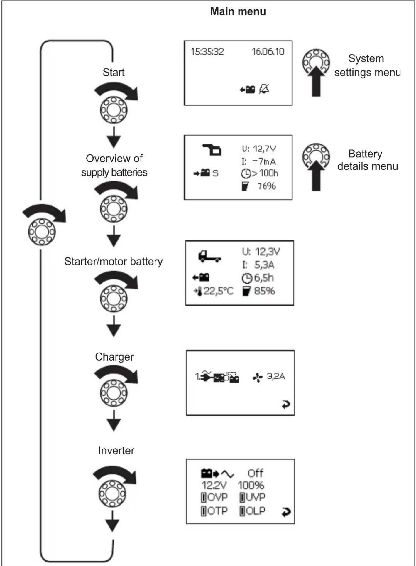
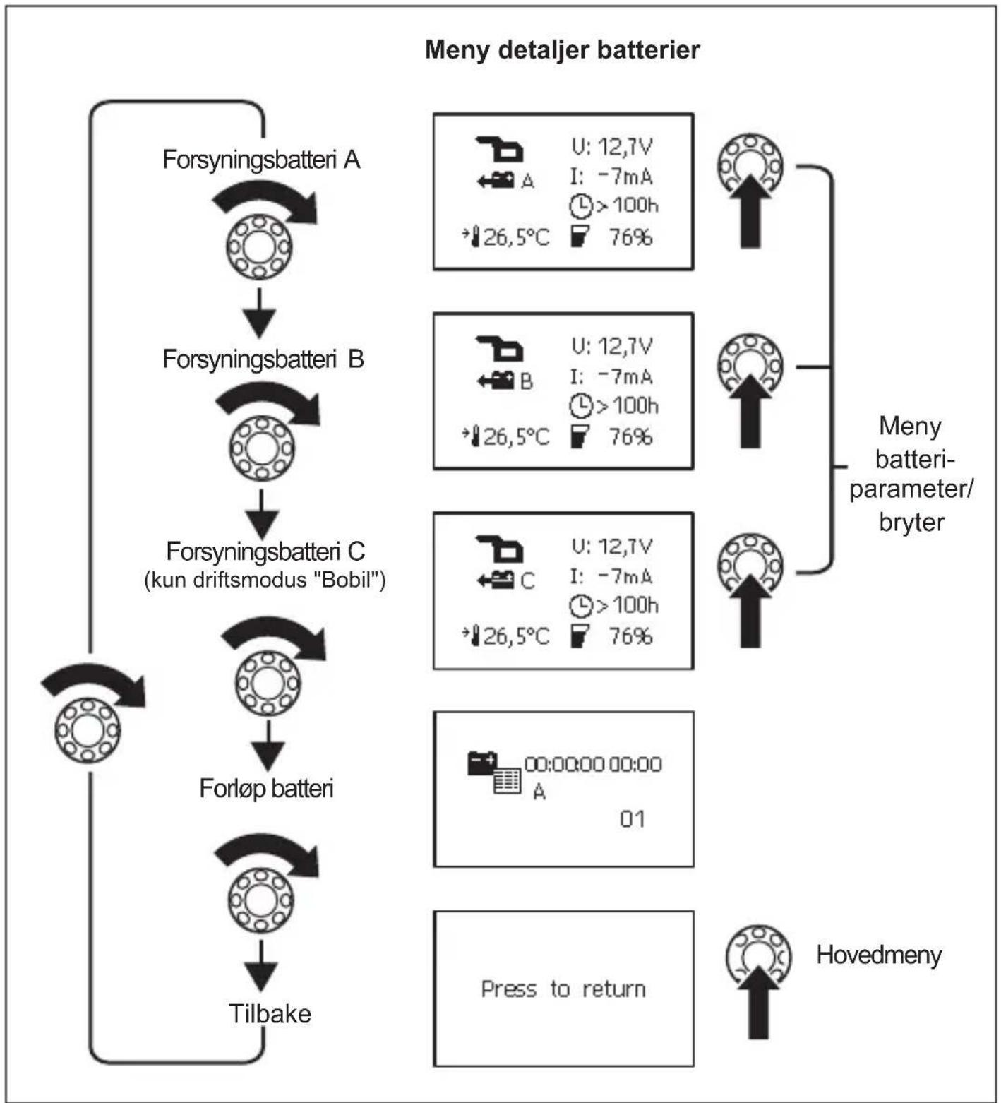
Navigating within the menu
Navigate through the menus as follows:
Turn the selector button (fig. 2, page 3) to scroll through the individual pages in the menu or through the items appearing on one page of the menu.
Press the selector button to access the sub-menus or change mode.
Turn the selector button until the message "Press to return" appears and then press the selector button.
This will return you to the "Main menu".
The following four figures show how you can navigate within the menu.
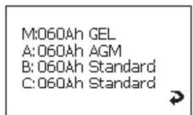
Battery parameters/switches menu

Changesettings
Output 1:80%
Output 2.50%
Output 3.90%

Changesettings

Main menu
Press to return
Display symbols
| Symbol Explanation | |
| Caravan starter battery | |
| Caravan supply battery | |
| Boat starter battery | |
| Boat supply battery | |
| Battery is charging | |
| Battery is being discharged by the consumer units connected | |
| S Summary of all battery values | |
| A Supply battery A | |
| B Supply battery B | |
| C Supply battery C | |
| M Starter battery | |
| U Operating voltage | |
| Positive value: Battery is charging Negative value: Battery is discharging | |
| Fan activated | |
| Charger 1 connected | |
| Battery history | |
| When battery is charging: remaining charge time When battery is discharging: remaining usage time | |
| Charge capacity in percent | |
| Battery temperature. This is only shown on the “Detailed view” menu pages for the individual batteries. | |
| Date, Time, Alarm | |
| Alarm On | |
| Alarm Off |
Changing values
Press the selector button so the value can be changed.
Turn the selector button to set the required value.
Press the selector button to save the value.
When values are being changed, an arrow appears (fig. 7 1, page 6).
Turn the selector button to mark the arrow.
Press the selector button to exit setting mode.
Turn the selector button until the message "Press to return" appears and then press the selector button.
This will return you to the "Main menu".
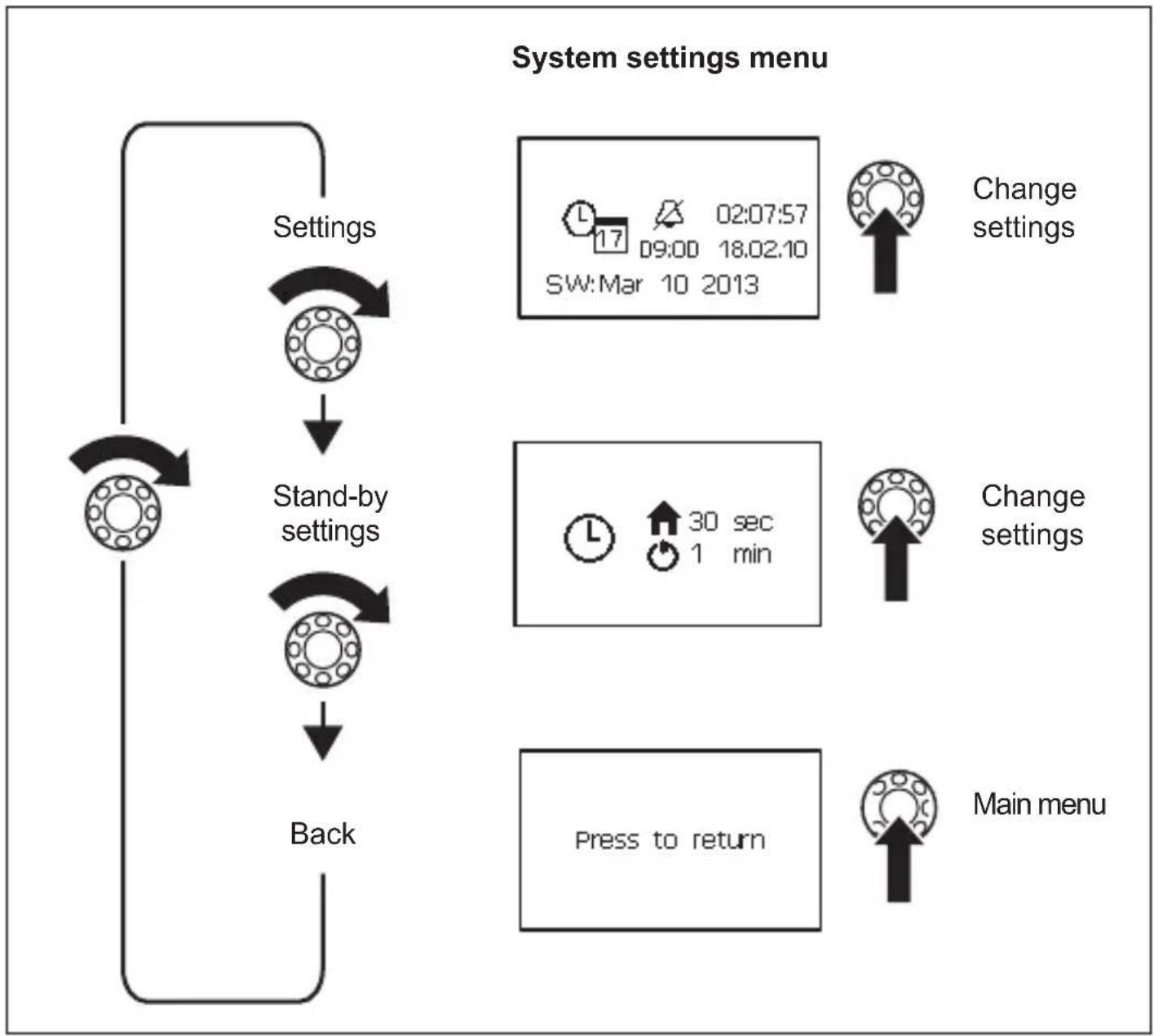
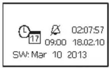
Changing system settings
Navigate to the "System settings" menu page (page 16), see chapter "Navigating within the menu" on page 14. Set the values for:
- Date and time
- A l a r m
Press the selector button.
Turn the selector button to access the relevant parameter.
Press the selector button and turn it to set the required value.
Confirm the value by pressing the selector button.
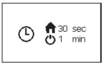
Setting time intervals
Navigate to the "Stand-by settings" menu page (page 16), see chapter "Navigating within the menu" on page 14.
Set the interval after which the main menu should appear automatically (fig. 8 1, page 6) or after which the MPC01 should switch to stand-by mode (fig. 8 2, page 6). You can choose between the following intervals: 30 sec, 1 min, 2 min, 10 min, "---" (continuous).
Set the required value, see chapter "Changing values" on page 21.
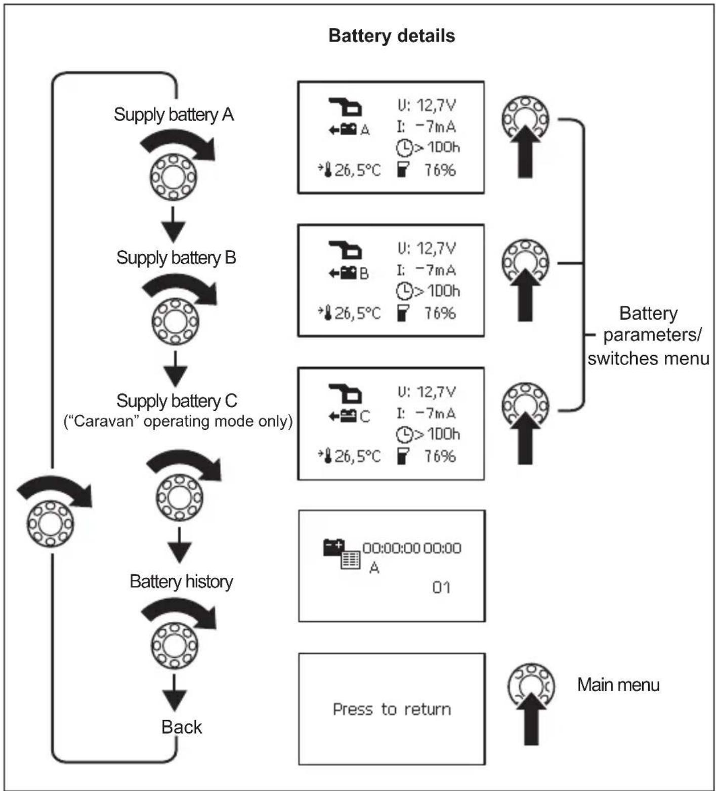
Reading battery values
Navigate to the menu page for the battery required, see chapter "Navigating within the menu" on page 14.

NOTE
The "Overview of supply batteries" menu page displays an average value for all supply batteries. The values of the starter battery (IBS_B1 connection) are not taken into consideration on this menu page. They are displayed on the "Starter battery" menu page.
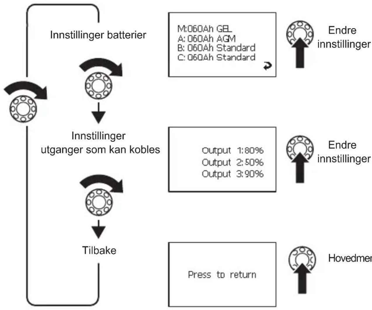
Changing the settings for batteries A, B and C
Navigate to the "Battery details" menu (page 17), see chapter "Navigating within the menu" on page 14.
Navigate to the menu page for the battery required.
Press the selector button to access setting mode.
Turn the selector button to mark the value to change.
Set the required value, see chapter "Changing values" on page 21.
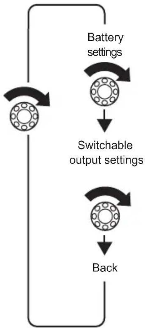
Programming the switchable outputs
You can define the switch points for switchable outputs 1-3 on the adapter board (fig. 5 1, 2, 5, page 5). The set value (10% -90%) is the total capacity of all batteries connected. If the value for the current total capacity is greater than the set value, then the output is switched to earth. If the value for the current total capacity is less than the set value, then the output is not connected to earth.
Navigate to the "Switchable output settings" menu page (page 18), see chapter "Navigating within the menu" on page 14.
Press the selector button to access setting mode.
Turn the selector button to mark the value to change.
Set the required value, see chapter "Changing values" on page 21.
Reading charger information and changing settings
Navigate to the "Charger" menu page (page 15), see chapter "Navigating within the menu" on page 14.
Press the selector button to access setting mode.
Turn the selector button to mark the value to change.
Set the required value, see chapter "Changing values" on page 21.
Reading inverter information
Navigate to the "Inverter" menu page (page 15), see chapter "Navigating within the menu" on page 14.
Viewing battery history

NOTE
An entry is only generated, if the battery is discharged to less than 5% (deep discharge) and afterwards charged to more than 95% capacity (full charge).
The menu page shows the date and time of battery charging and discharging processes. Up to 50 entries are saved.
Navigate to the "Battery history" menu page (page 17), see chapter "Navigating within the menu" on page 14.
9 G u a r a n t e e
The statutory warranty period applies. If the product is defective, please contact the manufacturer's branch in your country (see the back of the instruction manual for the addresses) on your retailer.
For repair and guarantee processing, please send the following items:
- Defect components
A copy of the receipt with purchasing date - A reason for the claim or description of the fault
10 Disposal
Place the packaging material in the appropriate recycling waste bins wherever possible.

If you wish to finally dispose of the product, ask your local recycling centre or specialist dealer for details about how to do this in accordance with the applicable disposal regulations.
11 Technical data
| MPC01 | |
| Ref. no.: 9102500073 | |
| Input voltage: 8 – 30 V--- | |
| Power consumption: 150 mA in display mode, | 10 mA in standby mode |
| Display dimensions (W x H x D): | 130 x 115 x 6 mm |
| Installation frame dimensions (W x H x D): | 150 x 136 x 16 mm |
| Certification: | CE E13 |
6 Description technique
6.1 Fonction
A:060Ah AGM
B:060Ah Standard
C:060Ah Standard


A: D60Ah AGM
B:060Ah Standard
C:060Ah Standard


Andra installinginga
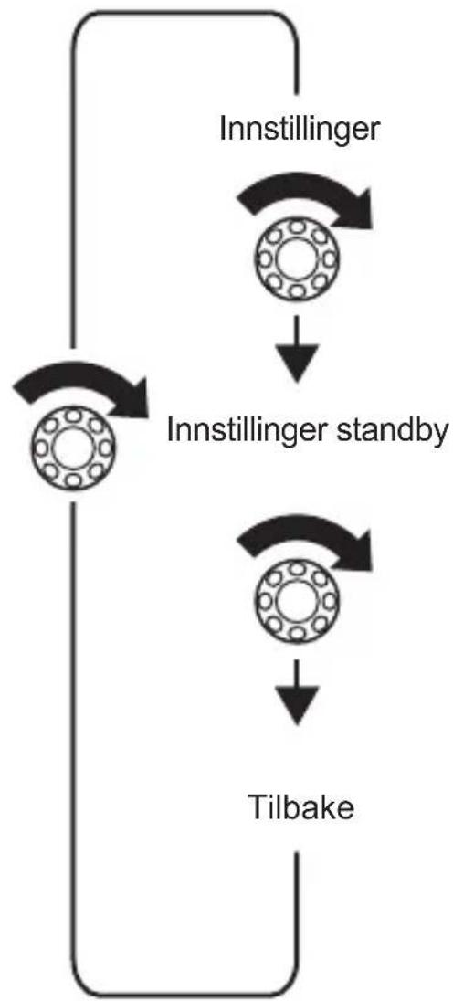
Meny systeminnstillinger


Meny bacteriparameter/bryter
Displaysymboler
| Symbol Forklaring | |
| Startbatteri bobil | |
| Forsyningsbatteri bobil | |
| Startbatteriimentary | |
| Forsyningsbatteriimentary | |
| Batteriet lades | |
| Batteriet lades ut av tilkobledeforbrukere | |
| S Sammenfatning av alle batteriverdier | |
| A Forsyningsbatteri A | |
| B Forsyningsbatteri B | |
| C Forsyningsbatteri C | |
| M Startbatteri | |
| U Driftsspenning | |
| I Positiv verdi: Batteriet lades | Negativ verdi: Batteriet utlades |
| Vifte på | |
| 1.500ml | Lader 1 tilkoblet |
| Forløp batteri | |
| Når batteriet lades: Resterende ladetid Når batteriet utlades: Resterende brukstid | |
| Ladekapasitet i prosent | |
| Batteriets temperatur Vises kun på menysidene «Detaljvisning» for hvert,enkelt batteri. | |
| Dato,klokkeslett, vekker | |
| Vekker en | |
| Vekker fra | |
Endre verdi
Endre systeminnstillinger
I3rOToBHTen He HecET HnKaKoI OTBeTCTBeHHOCTHa yUepe6 B CneDyUOuNX CnyuaX:
MoHTax Ha cTeHe (pnc. 4 A, cTp. 4)
BcTaBbTe Ka6eIb Ueenn ynpaBHeHn (1) B NOdknUoyehne Ha DnCnnee.
ПровадиTe Ka6eNB ueHn ynpaBneHnuepe3 n3В paMke.
YCTaHOBnTe DnCnIeN BMOHTaXHyIO paMKy.
3aKpeNITe MOHTaxHyIO paMKy I INcPNeB BXOJaUIMN B KOMPJIeKT NOCTaBKN YeTbIPbMn DInHHbIMN BINTAMN B IOxOJaUeM MecTe Ha CteHe.
3aKpeNITe NOKpbIbAIoUyIO paMky, YTO6bl OHa 3aUeJIKNHynaCb.
MoHTax B cTeHe (pnc. 4 B, cTp. 4)
CdaaTeBcTeHe na3 pa3mepom 11x9,9cm nIpy6nHO2,5 cm.
BcTaBbTe Ka6eNb ceN ynpaBneHn (1) B noKnIOyeHne Ha dinCpnee.
3aKpeHNTe DnCnneB BXOJLIMN B KOMJIeKT NOCTaBKN YeTbIPbM KOPOTKIMN BNHTaM.
3aKpeNITe NOKpbBaIOUyIO paMKy, YTO6bI OHa 3aUeINKHynacb.
7.4Прсоeннehne mOHTax coeHHTelbHOI ПlaTbI
ПиВИNTeКрБИшКУ И COeДИНТeЛьHуЮ ПИАу DBYМ RAHNTaM N IОДXOДЯSiEM MeCTe.
3aKpeHnTe npncoeHHhe Ka6eN NODXoJiIMn CpeCTBaMn, HApnpMeR, Ka6eNbHbIMN XOMyTaMn, YTO6bl NCKIIOHTb ONaCHOCTb OTPbBAHnI 8TEKePOB OT CoeINHtEnbHOI PnAtbl.

YKA3AHNE
- Kpa3bemy IBS_B2AdoJxHa 6bItb npncOeDHeHa KaK MmHmym OdHa nTtAoUa8 6atapeA, uTo6bMPC01 moT oTo6paXaTb daHhIe.
- Moxho npincoeHHnTb do Tpex nntaounx 6aTaapei (IBS_B2A, IBS_B2B n IBS_B2C) n Ondy cTapTepeHyIO 6aTaapeIO (IBS_B1).
B 3aBnCmOCTN OT KOJIueCTBa IprIcoeINHReMbIX NITaIOUx 6aTapei, nCNoIb3yIte CneDyUoUne pa3beMbI:
-Прсоeнене OdHOn ПntaIoSei 6aTapeN:IBS_B2A(pnc.510,ctp.5)
-ПисоeINHeHne AByx nIraUoInx 6aTapei: IBS_B2A (pnc.5 10, ctp.5) n IBS_B2B (pnc.57, ctp.5)
-Писоeннeпexпntaiox6aTapee:IBS_B2A(pnc.510,ctp.5),IBS_B2B (pnc.57,ctp.5)иIBS_B2C(pnc.59,ctp.5)
Прпсоeннгte nntaIOUne n coeHnTeNbHbIe Ka6eN n cpeyIoUm o6pa3OM:
CunTBiBaHHe npaMeTpOB 6aTapeN
ПерейдenteКстраицеMeHIOТpe6yemO6aTapeN,сM.П.«HabiruaЯВMeHIO»Ha cTp.205.

YKA3AHNE
Ha ctpaHnue MeHIO «O63Op nIITAOUx 6batapei» yka3bBaetc cpeDHee 3NaYeHne BCex nIITAOUx 6batapei. 3NaYeHnra cTapTePHO 6batapei (pa3bem IBS_B1) Ha eToi cTpaHnue MeHIO He yuHTbBAOTc. OHN oTO6paxaOTc H a cTpaHnue MeH6 «CtapTePHa 6batapei>.
I3meHHe hactpoek 6aTapei A,B,C
ПерейдnteКMeHIO«MeHIO daHHbIX aKKyMnyTopoB»(ctp.208),cM.rI.«HaBnraunB MeHIO»Ha ctp.205.
ПерейдпerteКстраицеменюТ trade mo6aTapeN.
IyBxOJaBpeXIMHaCTpoKnHaxMnte KHOkY BbI6opa.
Дя Вьдениня NOДпжалero ИЗмehию 3нayсеня NOВернite KHONky Bыбopa.
HacpoTe Tpe6yemoe 3NaueHne, cm. rI. «U3MeHeHne 3NaueHnra» Ha cTp. 212.
8 O b s I u h a M P 0
Pohyb v menu
V menu sa pohybujte takto:
dometic.com/sales-offices