
DCMPS520 - Saw DEWALT - Free user manual and instructions
Find the device manual for free DCMPS520 DEWALT in PDF.

| Product type | Cordless pole saw |
| Brand | DeWalt |
| Model | DCMPS520 |
| Rated voltage | 18 V DC |
| Battery type | Lithium-ion (Li-Ion) |
| Guide bar length | 20 cm |
| Maximum chain speed (no load) | 8.6 m/s |
| Maximum cutting length | 15 cm |
| Oil tank capacity | 55 ml |
| Weight (without battery pack) | 2.1 kg |
| Sound pressure level (LPA) | 84 dB(A) |
| Sound power level (LWA) | 92 dB(A) |
| Vibration emission value (ah) | 4.7 m/s² |
| Compatible batteries | DCB181, DCB182, DCB183, DCB184, DCB184B, DCB187, DCB189, DCB546, DCB547, DCB548, DCBP034, DCBP034G |
| Compatible chargers | DCB104, DCB107, DCB112, DCB113, DCB115, DCB116, DCB117, DCB118, DCB132, DCB119 |
| Intended use | Cutting branches and logs up to 15 cm in diameter |
| Lubrication system | Automatic, biodegradable oil recommended |
| Safety features | Motor brake, front hand guard, tip cover, low kickback guide bar |
| Routine maintenance | Cleaning air vents, chain tensioning and sharpening, checking oil level |
| Package contents (basic model) | Pruning saw, guide bar, 20 cm chain, cover, wrench, manual (battery and charger according to version) |
Frequently Asked Questions - DCMPS520 DEWALT
User questions about DCMPS520 DEWALT
0 question about this device. Answer the ones you know or ask your own.
Ask a new question about this device
Download the instructions for your Saw in PDF format for free! Find your manual DCMPS520 - DEWALT and take your electronic device back in hand. On this page are published all the documents necessary for the use of your device. DCMPS520 by DEWALT.
USER MANUAL DCMPS520 DEWALT
English (original instructions) 36
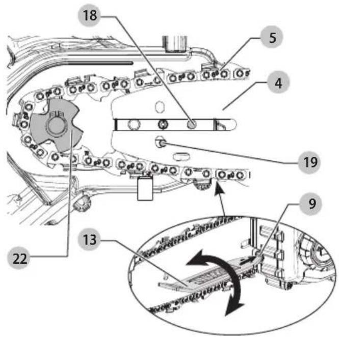
Fig. E
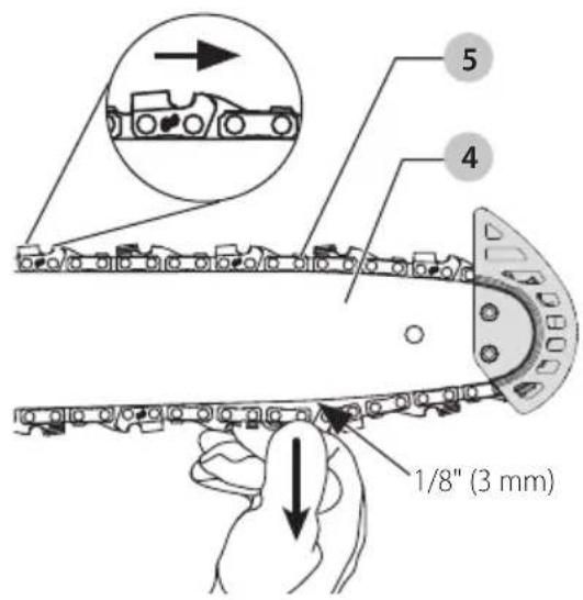
Fig. F
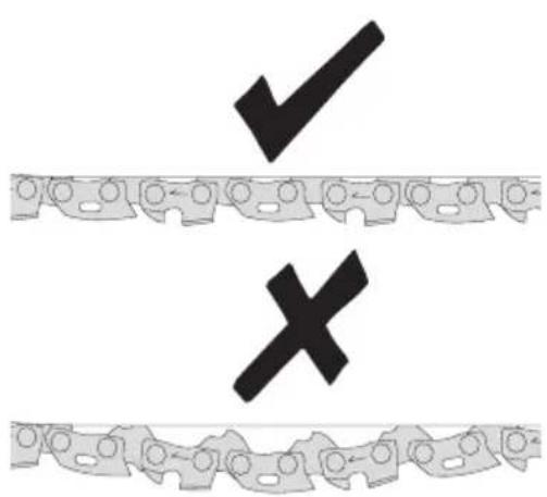
Fig. G Fig. H
natural_image
Diagram showing two vehicle tracks with a magnified inset of a car silhouette (no text or symbols)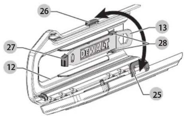
Fig. I Fig. J

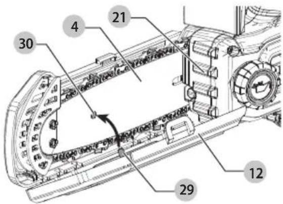
Fig. K
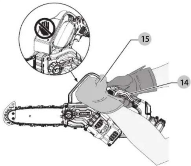
Fig. L
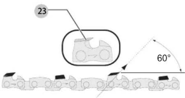
Fig. M Fig. N
18V BESKÆRINGSSAV
DCMPS520
Tillykke!
natural_image
Technical line drawing of a mechanical component with no visible text or symbolsnatural_image
Diagram of a tree trunk with embedded soil layers and directional arrows indicating movement or flow (no text or symbols)Opskæring
natural_image
Technical illustration of a mechanical assembly with a pulley and wooden frame (no text or symbols)-
OVERSNIT (1/3 DIAMETER) FOR AT UNDGÅ SPLINTRING
-
UNDERSNIT (2/3 DIAMETER) FOR AT M∅DE 1. SNIT (FOR AT UNDGÅ KLEMNING)
Vice-President Engineering, PTE-Europe
natural_image
Technical line drawing of a mechanical component with no visible text or symbolsnatural_image
Diagram of a tree trunk with leaves and soil layers, showing directional arrows indicating movement or flow (no text or symbols)Ablängen
natural_image
Technical illustration of a mechanical assembly with a conveyor belt and wooden frame (no text or symbols)You have chosen a DEWALT tool. Years of experience, thorough product development and innovation make DEWALT one of the most reliable partners for professional power tool users.
Technical Data
| DCMPS520 | |||
| Voltage V | DC | 18 | |
| Type 1 | |||
| Battery type Li-Ion | |||
| Bar Length cm 20 | |||
| Maximum Chain Speed (no-load) m/s 8.6 | |||
| Maximum Cutting Length cm 15 | |||
| Oil Capacity ml 55 | |||
| Weight (without battery pack) kg 2.1 | |||
| Noise values and vibration values (triax vector sum) according to EN62841-4-1: | |||
| L_PA (emission sound pressure level at no load) | dB(A) | 84 | |
| L_WA (sound power level at no load) | dB(A) | 92 | |
| K(uncertainty for the given sound level) | dB | 3.0 | |
| Vibration emission value a_h = | m/s2 | 4.7 | |
| Uncertainty K = | m/s2 | 1.5 | |
The vibration and/or noise emission level given in this information sheet has been measured in accordance with a standardised test given in EN62841 and may be used to compare one tool with another. It may be used for a preliminary assessment of exposure.
WARNING: The declared vibration and/or noise emission level represents the main applications of the tool. However, if the tool is used for different applications, with different accessories or is poorly maintained, the vibration and/or noise emission may differ. This may significantly increase the exposure level over the total working period.
An estimation of the level of exposure to vibration and/or noise should also take into account the times when the tool is switched off or when it is running but not actually doing the job. This may significantly reduce the exposure level over the total working period.
Identify additional safety measures to protect the operator from the effects of vibration and/or noise such as: maintain the tool and the accessories, keep the hands warm (relevant for vibration), organisation of work patterns.
EC-Declaration of Conformity
Machinery Directive

Pruner Saw
DCMPS520
DEWALT declares that these products described under
Technical Data are in compliance with:
2006/42/EC, EN62841-1:2015+A11:2022, VDE-PB-0023:2022-08.
EC type-examination by
L_WA (measured sound power level) 96 dB(A)
L_WA (guaranteed sound power) 99 dB(A)
These products also comply with Directive 2014/30/EU and 2011/65/EU. For more information, please contact DEWALT at the following address or refer to the back of the manual.
The undersigned is responsible for compilation of the technical file and makes this declaration on behalf of DEWALT.

Markus Rompel
Vice-President Engineering, PTE-Europe
65510, Idstein, Germany
10.05.2023
| Batteries Chargers/Charge | Times (Minutes)*** | ||||||||||||
| Cat # V | DC | Ah Weight (kg) | DCB104 DCB107 | DCB112/DCB1102 | DCB113 | DCB115/DCB1104 | DCB116 DCB117 DCB118 DCB132 DCB119 | ||||||
| DCB546 | 18/54 | 6.0/2.0 | 1.08 | 60 | 270 | 170 | 140 | 90 | 80 | 40 | 60 | 90 | X |
| DCB547 | 18/54 | 9.0/3.0 | 1.46 | 75* | 420 | 270 | 220 | 135* | 110* | 60 | 75* | 135* | X |
| DCB548 | 18/54 | 12.0/4.0 | 1.46 | 120 | 540 | 350 | 300 | 180 | 150 | 80 | 120 | 180 | X |
| DCB181 | 18 | 1.5 | 0.35 | 22 | 70 | 45 | 35 | 22 | 22 | 22 | 22 | 22 | 45 |
| DCB182 | 18 | 4.0 | 0.61 | 60/40** | 185 | 120 | 100 | 60 | 60/45** | 60/40** | 60/40** | 60 | 120 |
| DCB183 | 18 | 2.0 | 0.40 | 30 | 90 | 60 | 50 | 30 | 30 | 30 | 30 | 30 | 60 |
| DCB184/B | 18 | 5.0 | 0.62 | 75/50** | 240 | 150 | 120 | 75 | 75/60** | 75/50** | 75/50** | 75 | 150 |
| DCB187 | 18 | 3.0 | 0.54 | 45 | 140 | 90 | 70 | 45 | 45 | 45 | 45 | 45 | 90 |
| DCB189 | 18 | 4.0 | 0.54 | 60 | 185 | 120 | 100 | 60 | 60 | 60 | 60 | 60 | 120 |
| DCBP034/G | 18 | 1.7 | 0.32 | 27 | 82 | 50 | 40 | 27 | 27 | 27 | 27 | 27 | 50 |
*Date code 201811475B or later
**Date code 201536 or later
***Battery charge times matrix provided for guidance only; charge times will vary depending on temperature and condition of batteries.
DECLARATION OF CONFORMITY THE SUPPLY OF MACHINERY (SAFETY) REGULATIONS 2008

Pruner Saw
DCMPS520
DEWALT declares that these products described under
Technical Data are in compliance with:
The Supply of Machinery (Safety) Regulations, 2008, S.I. 2008/1597
(as amended), EN 62841-1:2015+A11:2022, VDE-PB-0023:2022-08.
UKCA Type Examination by
Technology International (Europe) Ltd
56 Shrivenham Hundred Business Park, Watchfield, Swindon,
SN6 8TY, Great Britain
Body number: 0673
UK Machinery Type-examination Certificate Number:
TI(E) / SOMSR(08) - UKTE / 110 / 05052023
The Noise Emission in the Environment by Equipment for use Outdoors Regulations 2001, S.I. 2001/1701 (as amended), Schedule 8.
L_WA (measured sound power level) 96 dB(A)
L_WA (guaranteed sound power) 99 dB(A)
These products conform to the following UK Regulations Electromagnetic Compatibility Regulations, 2016, S.I.2016/1091 (as amended).
The Restriction of the Use of Certain Hazardous Substances in Electrical and Electronic Equipment Regulations 2012, S.I. 2012/3032 (as amended).
For more information, please contact DEWALT at the following address or refer to the back of the manual.
The undersigned is responsible for compilation of the technical file and makes this declaration on behalf of DEWALT.

Paul Featherstone
Product Director – Outdoor Products Group
DEWALT, UK,
270 Bath Road, Slough
Birkshire SL1 4DX
England
10.05.2023

WARNING: To reduce the risk of injury, read the instruction manual.
Definitions: Safety Guidelines
The definitions below describe the level of severity for each signal word. Please read the manual and pay attention to these symbols.

DANGER: Indicates an imminently hazardous situation which, if not avoided, will result in death or serious injury.

WARNING: Indicates a potentially hazardous situation which, if not avoided, could result in death or serious injury.

CAUTION: Indicates a potentially hazardous situation which, if not avoided, may result in minor or moderate injury.
NOTICE: Indicates a practice not related to personal injury which, if not avoided, may result in property damage.

Denotes risk of electric shock.

Denotes risk of fire.
GENERAL POWER TOOL SAFETY WARNINGS
WARNING: Read all safety warnings, instructions, indications and specifications provided with this
power tool. Failure to follow all instructions listed below may result in electric shock, fire and/or serious injury.
SAVE ALL WARNINGS AND INSTRUCTIONS FOR FUTURE REFERENCE
The term "power tool" in the warnings refers to your mains-operated (corded) power tool or battery-operated (cordless) power tool.
1) Work Area Safety
a) Keep work area clean and well lit. Cluttered or dark areas invite accidents.
b) Do not operate power tools in explosive atmospheres, such as in the presence of flammable liquids, gases or dust. Power tools create sparks which may ignite the dust or fumes.
c) Keep children and bystanders away while operating a power tool. Distractions can cause you to lose control.
2) Electrical Safety
a) Power tool plugs must match the outlet. Never modify the plug in any way. Do not use any adapter plugs with earthed (grounded) power tools.
Unmodified plugs and matching outlets will reduce risk of electric shock.
b) Avoid body contact with earthed or grounded surfaces, such as pipes, radiators, ranges and refrigerators. There is an increased risk of electric shock if your body is earthed or grounded.
c) Do not expose power tools to rain or wet conditions.
Water entering a power tool will increase the risk of electric shock.
d) Do not abuse the cord. Never use the cord for carrying, pulling or unplugging the power tool. Keep cord away from heat, oil, sharp edges or moving parts. Damaged or entangled cords increase the risk of electric shock.
e) When operating a power tool outdoors, use an extension cord suitable for outdoor use. Use of a cord suitable for outdoor use reduces the risk of electric shock.
f) If operating a power tool in a damp location is unavoidable, use a residual current device (RCD) protected supply. Use of an RCD reduces the risk of electric shock.
3) Personal Safety
a) Stay alert, watch what you are doing and use common sense when operating a power tool. Do not use a power tool while you are tired or under the influence of drugs, alcohol or medication. A moment of inattention while operating power tools may result in serious personal injury.
b) Use personal protective equipment. Always wear eye protection. Protective equipment such as a dust mask, non-skid safety shoes, hard hat or hearing protection used for appropriate conditions will reduce personal injuries.
c) Prevent unintentional starting. Ensure the switch is in the off position before connecting to power source and/or battery pack, picking up or carrying the tool. Carrying power tools with your finger on the switch or energising power tools that have the switch on invites accidents.
d) Remove any adjusting key or wrench before turning the power tool on. A wrench or a key left attached to a rotating part of the power tool may result in personal injury.
e) Do not overreach. Keep proper footing and balance at all times. This enables better control of the power tool in unexpected situations.
f) Dress properly. Do not wear loose clothing or jewellery. Keep your hair and clothing away from moving parts. Loose clothes, jewellery or long hair can be caught in moving parts.
g) If devices are provided for the connection of dust extraction and collection facilities, ensure these are connected and properly used. Use of dust collection can reduce dust-related hazards.
h) Do not let familiarity gained from frequent use of tools allow you to become complacent and ignore tool safety principles. A careless action can cause severe injury within a fraction of a second.
4) Power Tool Use and Care
a) Do not force the power tool. Use the correct power tool for your application. The correct power tool will do the job better and safer at the rate for which it was designed.
b) Do not use the power tool if the switch does not turn it on and off. Any power tool that cannot be controlled with the switch is dangerous and must be repaired.
c) Disconnect the plug from the power source and/or remove the battery pack, if detachable, from the power tool before making any adjustments, changing accessories, or storing power tools. Such preventive safety measures reduce the risk of starting the power tool accidentally.
d) Store idle power tools out of the reach of children and do not allow persons unfamiliar with the power tool or these instructions to operate the power tool. Power tools are dangerous in the hands of untrained users.
e) Maintain power tools and accessories. Check for misalignment or binding of moving parts, breakage of parts and any other condition that may affect the power tool's operation. If damaged, have the power tool repaired before use. Many accidents are caused by poorly maintained power tools.
f) Keep cutting tools sharp and clean. Properly maintained cutting tools with sharp cutting edges are less likely to bind and are easier to control.
g) Use the power tool, accessories and tool bits, etc. in accordance with these instructions, taking into account the working conditions and the work to be performed. Use of the power tool for operations different from those intended could result in a hazardous situation.
h) Keep handles and grasping surfaces dry, clean and free from oil and grease. Slippery handles and grasping surfaces do not allow for safe handling and control of the tool in unexpected situations.
5) Battery Tool Use and Care
a) Recharge only with the charger specified by the manufacturer. A charger that is suitable for one type of battery pack may create a risk of fire when used with another battery pack.
b) Use power tools only with specifically designated battery packs. Use of any other battery packs may create a risk of injury and fire.
c) When battery pack is not in use, keep it away from other metal objects, like paper clips, coins, keys, nails, screws or other small metal objects, that can make a connection from one terminal to another. Shorting the battery terminals together may cause burns or a fire.
d) Under abusive conditions, liquid may be ejected from the battery; avoid contact. If contact accidentally occurs, flush with water. If liquid contacts eyes, additionally seek medical help. Liquid ejected from the battery may cause irritation or burns.
e) Do not use a battery pack or tool that is damaged or modified. Damaged or modified batteries may exhibit unpredictable behaviour resulting in fire, explosion or risk of injury.
f) Do not expose a battery pack or tool to fire or excessive temperature. Exposure to fire or temperature above 130 °C may cause explosion.
g) Follow all charging instructions and do not charge the battery pack or tool outside the temperature range specified in the instructions. Charging improperly or at temperatures outside the specified range may damage the battery and increase the risk of fire.
6) Service
a) Have your power tool serviced by a qualified repair person using only identical replacement parts. This will ensure that the safety of the power tool is maintained.
b) Never service damaged battery packs. Service of battery packs should only be performed by the manufacturer or authorised service providers.
Pruner Safety Warnings
a) Keep all parts of the body away from the saw chain when the pruner is operating. Before you start the pruner, make sure the saw chain is not contacting anything. A moment of inattention while operating pruners may cause entanglement of your clothing or body with the saw chain.
b) Always hold the pruner with your right hand on the rear handle and your left hand on the front handle. Holding the pruner with a reversed hand configuration increases the risk of personal injury and should never be done.
c) Hold the pruner by insulated gripping surfaces only, because the saw chain may contact hidden wiring.
Saw chains contacting a "live" wire may make exposed metal parts of the pruner "live" and could give the operator an electric shock.
d) Wear safety glasses and hearing protection. Further protective equipment for, head, hands, legs and feet is recommended. Adequate protective clothing will reduce personal injury from flying debris or accidental contact with the saw chain.
e) Do not operate a pruner saw in a tree, on a ladder, from a rooftop, or any unstable support. Operation of a pruner saw in this manner could result in serious personal injury.
f) Always keep proper footing and operate the pruner only when standing on fixed, secure and level surface. Slippery or unstable surfaces may cause a loss of balance or control of the pruner.
g) When cutting a limb that is under tension, be alert for spring back. When the tension in the wood fibers is released, the spring loaded limb may strike the operator and/or throw the pruner out of control.
h) Use extreme caution when cutting brush and saplings. The slender material could catch the saw chain and be whipped toward you or pull you off balance.
i) Carry the pruner with the pruner switched off and away from your body. When transporting or storing the pruner always fit the guide bar cover. Proper handling of the pruner will reduce the likelihood of accidental contact with the moving saw chain.
j) Follow instructions for lubricating, chain tensioning and changing the bar and saw chain. Improperly tensioned or lubricated chain could break the pruner chain.
k) Keep handles dry, clean, and free from oil and grease. Greasy, oily handles are slippery, causing loss of control.
1) Cut wood only. Do not use pruner for purposes not intended. For example: do not use pruner for cutting metal, plastic, masonry or non-wood building materials. Use of the pruner for operations different than intended could result in a hazardous situation.
m) Maintain a firm grip, with thumbs and fingers encircling the pruner handles, with both hands on the pruner. Maintaining control of the pruner will reduce the risk of losing control. Do not let go of the pruner.
n) Do not overreach and do not cut above shoulder height. This enables better control of the pruner in unexpected situations.
o) Only use replacement bars and chains specified by the manufacturer. Incorrect replacement bars and chains can cause chain breakage and increase the risk of injury.
p) Follow the manufacturer's sharpening and maintenance instructions for the pruner chain. Decreasing the depth gauge height can lead to increased risk of injury.
q) This pruner is not intended for tree felling. Use of the pruner for operations different than intended could result in serious injury to the operator or bystander.
r) Follow all instructions when clearing jammed material, storing or servicing the pruner saw. Make sure the switch is off and the battery pack is removed.
Causes and Operator Prevention of Kickback:
Kickback may occur when the nose or tip of the guide bar touches an object, or when the wood closes in and pinches the saw chain in the cut.
Tip contact in some cases may cause a sudden reverse reaction, kicking the guide bar up and back towards the operator.
Pinching the saw chain along the top of the guide bar may push the guide bar rapidly back towards the operator.
Either of these reactions may cause you to lose control of the saw which could result in serious personal injury. Do not rely exclusively upon the safety devices built into your saw. As a pruner user, you should take several steps to keep your cutting jobs free from accident or injury.
Kickback is the result of tool misuse and/or incorrect operating procedures or conditions and can be avoided by taking proper precautions as given below:
a) Maintain a firm grip, with thumbs and fingers encircling the pruner handles, with both hands on the saw and position your body and arm to allow you to resist kickback forces. Kickback forces can be controlled by the operator, if proper precautions are taken. Do not let go of the pruner.
b) Do not overreach and do not cut above shoulder height. This helps prevent unintended tip contact and enables better control of the pruner in unexpected situations.
c) Only use replacement bars and chains specified by the manufacturer. Incorrect replacement bars and chains may cause chain breakage and/or kickback.
d) Follow the manufacturer's sharpening and maintenance instructions for the saw chain. Decreasing the depth gauge height can lead to increased kickback.
The Following Precautions Should Be Followed to Minimize Kickback:
- Grip saw firmly. Hold the pruner firmly with both hands when the motor is running. Use a firm grip with thumbs and fingers encircling the pruner handles. Pruner will pull forward when cutting on the bottom edge of the bar, and push backward when cutting along the top edge of the bar.
- Do not over reach.
- Keep proper footing and balance at all times.
- Don't let the nose of the guide bar contact a log, branch, ground or other obstruction.
- Don't cut above shoulder height.
- Use devices such as low kickback chain and reduced kickback guide bars that reduce the risks associated with kickback.
-
Only use replacement bars and saw chains specified by the manufacturer or the equivalent.
-
Never let the moving saw chain contact any object at the tip of the guide bar.
-
Keep the working area free from obstructions such as other trees, branches, rocks, fences, stumps, etc. Eliminate or avoid any obstruction that your saw chain could hit while you are cutting through a particular log or branch.
-
Keep your saw chain sharp and properly tensioned. A loose or dull chain can increase the chance of kickback. Check tension at regular intervals with the motor stopped and tool unplugged, never with the motor running.
-
Begin and continue cutting only with the chain moving at full speed. If the chain is moving at a slower speed, there is a greater chance for kickback to occur.
-
Cut one log at a time.
-
Use extreme caution when re-entering a previous cut. Engage the ribbed bumpers 21 onto the wood and allow the chain to reach full speed before proceeding with a cut.
-
Do not attempt plunge cuts or bore cuts.
-
Watch for shifting logs or other forces that could close a cut and pinch or fall into chain.
Kickback Safety Features
WARNING: The following features are included on your saw to help reduce the hazard of kickback; however such features will not totally eliminate this dangerous reaction. As a pruner user do not rely only on safety devices. You must follow all safety precautions, instructions, and maintenance in this manual to help avoid kickback and other forces which can result in serious injury.
- Reduced-Kickback Guide Bar, designed with a small radius tip which reduces the size of the kickback danger zone on bar tip. A reduced-kickback guide bar is one which has been demonstrated to significantly reduce the number and seriousness of kickbacks when tested in accordance with safety requirements for electric pruners.
- Low-Kickback Chain, designed with a contoured depth gauge and guard link which deflects kickback force and allows wood to gradually ride into the cutter. A low-kickback chain is a chain which has met kickback performance requirements of ANSI B175.1–2012.
- Do not operate pruner while in a tree, on a ladder, on a scaffold, or from any unstable surface.
- Hold tool by insulated gripping surfaces when performing an operation where the cutting tool may contact hidden wiring. Contact with a "live" wire will make exposed metal parts of the tool "live" and shock the operator.
- Do not attempt operations beyond your capacity or experience. Read thoroughly and understand completely all instructions in this manual.
- Before you start pruner, make sure saw chain is not contacting any object.
- Do not operate a pruner with one hand! Serious injury to the operator, helpers, or bystanders may result from one-handed operation. A pruner is intended for two-handed use only.
- Keep the handles dry, clean, and free of oil or grease.
- Do not allow dirt, debris, or sawdust to build up on the motor or outside air vents.
-
Stop the pruner before setting it down.
-
Do not cut vines and/or small under-brush.
- Use extreme caution when cutting small size brush and saplings because slender material may catch the saw chain and be whipped toward you or pull you off balance.
Pruner Names and Terms
- Bucking - The process of cross-cutting a felled tree or log into lengths.
- Motor Brake (if equipped) - A device used to stop the saw chain when the trigger is released.
- Pruner Powerhead - A pruner without the saw chain and guide bar.
- Drive Sprocket or Sprocket - The toothed part that drives the saw chain.
• Felling - The process of cutting down a tree.
- Felling Back Cut - The final cut in a tree felling operation made on the opposite side of the tree from the notching cut.
- Front Handle - The support handle located at or toward the front of the pruner.
- Front Hand Guard - A structural barrier between the front handle of a pruner and the guide bar, typically located close to the hand position on the front handle.
- Guide Bar - A solid railed structure that supports and guides the saw chain.
- Scabbard/Guide Bar Cover - Enclosure fitted over guide bar to help prevent tooth contact when saw is not in use.
- Kickback - The backward or upward motion, or both of the guide bar occurring when the saw chain near the nose of the top area of the guide bar contacts any object such as a log or branch, or when the wood closes in and pinches the saw chain in the cut.
- Kickback, Pinch - The rapid pushback of the saw which can occur when the wood closes in and pinches the moving saw chain in the cut along the top of the guide bar.
- Kickback, Rotational - The rapid upward and backward motion of the saw which can occur when the moving saw chain near the upper portion of the tip of the guide bar contacts an object, such as a log or branch.
- Limbing - Removing the branches from a fallen tree.
- Low-Kickback Chain - A chain that complies with the kickback performance requirements of ANSI B175.1–2012 (when tested on a representative sample of pruners).
- Normal Cutting Position - Those positions assumed in performing the bucking and felling cuts.
- Notching Undercut - A notch cut in a tree that directs the tree's fall.
- Rear Handle - The support handle located at or toward the rear of the saw.
- Reduced Kickback Guide Bar - A guide bar which has been demonstrated to reduce kickback significantly.
- Replacement Saw Chain - A chain that complies with kickback performance requirements of ANSI B175.1–2012 when tested with specific pruners. It may not meet the ANSI performance requirements when used with other saws.
- Saw Chain - A loop of chain having cutting teeth, that cut the wood, and that is driven by the motor and is supported by the guide bar.
- Ribbed Bumper - The ribs used when felling or bucking to pivot the saw and maintain position while sawing.
- Switch - A device that when operated will complete or interrupt an electrical power circuit to the motor of the pruner.
- Switch Linkage - The mechanism that transmits motion from a trigger to the switch.
- Switch Lockout - A movable stop that prevents the unintentional operation of the switch until manually actuated.
Residual Risks
In spite of the application of the relevant safety regulations and the implementation of safety devices, certain residual risks cannot be avoided. These are:
- Impairment of hearing.
- Risk of personal injury due to flying particles.
- Risk of burns due to accessories becoming hot during operation.
- Risk of personal injury due to prolonged use.
SAVE THESE INSTRUCTIONS
Chargers
DEWALT chargers require no adjustment and are designed to be as easy as possible to operate.
Electrical Safety
The electric motor has been designed for one voltage only. Always check that the battery pack voltage corresponds to the voltage on the rating plate. Also make sure that the voltage of your charger corresponds to that of your mains.

Your DEWALT charger is double insulated in accordance with EN60335; therefore, no earth wire is required.
If the supply cord is damaged, it must be replaced only by DEWALT or an authorised service organisation.
Mains Plug Replacement (U.K. & Ireland Only)
If a new mains plug needs to be fitted:
• Safely dispose of the old plug.
- Connect the brown lead to the live terminal in the plug.
- Connect the blue lead to the neutral terminal.
WARNING: No connection is to be made to the terminal.
Follow the fitting instructions supplied with good quality plugs. Recommended fuse: 3 A.
Using an Extension Cable
An extension cord should not be used unless absolutely necessary. Use an approved extension cable suitable for the power input of your charger (see Technical Data). The minimum conductor size is 1 mm ^3 ; the maximum length is 30 m.
When using a cable reel, always unwind the cable completely.
Important Safety Instructions for All Battery Chargers
save THEsE InsTRUcTIOns: This manual contains important safety and operating instructions for compatible battery chargers (refer to Technical Data).
- Before using charger, read all instructions and cautionary markings on charger, battery pack, and product using battery pack.
WARNING: Shock hazard. Do not allow any liquid to get inside charger. Electric shock may result.
WARNING: We recommend the use of a residual current rating with a residual current rating of 30mA or less.
CAUTION: Burn hazard. To reduce the risk of injury, charge only DEWALT rechargeable batteries. Other types of batteries may burst, causing personal injury and damage.
CAUTION: Children should be supervised to ensure that they do not play with the appliance.
NOTICE: Under certain conditions, with the charger plugged into the power supply, the exposed charging contacts inside the charger can be shorted by foreign material. Foreign materials of a conductive nature such as, but not limited to, steel wool, aluminum foil or any buildup of metallic particles should be kept away from charger cavities. Always unplug the charger from the power supply when there is no battery pack in the cavity. Unplug charger before attempting to clean.
- DO NOT attempt to charge the battery pack with any chargers other than the ones in this manual. The charger and battery pack are specifically designed to work together.
• These chargers are not intended for any uses other than charging DEWALT rechargeable batteries. Any other uses may result in risk of fire, electric shock or electrocution. - Do not expose charger to rain or snow.
- Pull by plug rather than cord when disconnecting charger. This will reduce risk of damage to electric plug and cord.
- Make sure that cord is located so that it will not be stepped on, tripped over, or otherwise subjected to damage or stress.
- Do not use an extension cord unless it is absolutely necessary. Use of improper extension cord could result in risk of fire, electric shock, or electrocution.
- Do not place any object on top of charger or place the charger on a soft surface that might block the ventilation slots and result in excessive internal heat. Place the charger in a position away from any heat source. The charger is ventilated through slots in the top and the bottom of the housing.
- Do not operate charger with damaged cord or plug—have them replaced immediately.
- Do not operate charger if it has received a sharp blow, been dropped, or otherwise damaged in any way. Take it to an authorised service centre.
- Do not disassemble charger; take it to an authorised service centre when service or repair is required. Incorrect
reassembly may result in a risk of electric shock, electrocution or fire.
- In case of damaged power supply cord, the supply cord must be replaced immediately by the manufacturer, its service agent or similar qualified person to prevent any hazard.
- Disconnect the charger from the outlet before attempting any cleaning. This will reduce the risk of electric shock. Removing the battery pack will not reduce this risk.
- NEVER attempt to connect two chargers together.
- The charger is designed to operate on standard 230V household electrical power. Do not attempt to use it on any other voltage. This does not apply to the vehicular charger.
Charging a Battery (Fig. B)
nOTE: To ensure maximum performance and life of lithium-ion battery packs, charge the battery pack fully before first use.
- Plug the charger into an appropriate outlet before inserting battery pack.
- Insert the battery pack 16 into the charger, making sure the battery pack is fully seated in the charger. The red (charging) light will blink repeatedly indicating that the charging process has started.
- The Stage 1 charging blink indicator represents the charge process that charges the majority of the battery's capacity. Stage 2 charging blink indicator represents the remainder, or top off charge process, for the battery to reach full capacity.
- The completion of charge for Stage 1 or Stage 2 will be indicated by the stage's light remaining ON continuously. The battery pack is fully charged when both Stage 1 and Stage 2 charging lights remain ON continuously, and it may be removed and used at this time or left in the charger.
nOTE: To remove the battery pack, some chargers require the battery pack release button 17 to be pressed.
Refer to the indicators below for the charge status of the battery pack.
Indicators
| Stage 1 Charging | — — | | |
| Stage 2 Charging | — | — — | |
| Fully Charged | — | — — | |
| Hot/Cold Pack Delay* | — — — | |
* The red light will continue to blink, but a yellow indicator light will be illuminated during this operation. Once the battery pack has reached an appropriate temperature, the yellow light will turn off and the charger will resume the charging procedure. The compatible charger(s) will not charge a faulty battery pack. The charger will indicate faulty battery by refusing to light.
nOTE: This could also mean a problem with a charger.
If the charger indicates a problem, take the charger and battery pack to be tested at an authorised service centre.
Hot/Cold Pack Delay
When the charger detects a battery pack that is too hot or too cold, it automatically starts a Hot/Cold Pack Delay, suspending charging until the battery pack has reached an appropriate temperature. The charger then automatically switches to the pack charging mode. This feature ensures maximum battery pack life.
A cold battery pack will charge at a slower rate than a warm battery pack. The battery pack will charge at that slower rate throughout the entire charging cycle and will not return to maximum charge rate even if the battery pack warms.
The DCB118 charger is equipped with an internal fan designed to cool the battery pack. The fan will turn on automatically when the battery pack needs to be cooled. Never operate the charger if the fan does not operate properly or if ventilation slots are blocked. Do not permit foreign objects to enter the interior of the charger.
Electronic Protection System
XR Li-Ion tools are designed with an Electronic Protection System that will protect the battery pack against overloading, overheating or deep discharge.
The tool will automatically turn off if the Electronic Protection System engages. If this occurs, place the lithium-ion battery pack on the charger until it is fully charged.
Wall Mounting
These chargers are designed to be wall mountable or to sit upright on a table or work surface. If wall mounting, locate the charger within reach of an electrical outlet, and away from a corner or other obstructions which may impede air flow. Use the back of the charger as a template for the location of the mounting screws on the wall. Mount the charger securely using drywall screws (purchased separately) at least 25.4 mm long with a screw head diameter of 7–9 mm, screwed into wood to an optimal depth leaving approximately 5.5 mm of the screw exposed. Align the slots on the back of the charger with the exposed screws and fully engage them in the slots.
Charger Cleaning Instructions
WARNING: Shock hazard. Disconnect the charger from the AC outlet before cleaning. Dirt and grease may be removed from the exterior of the charger using a cloth or soft non-metallic brush. Do not use water or any cleaning solutions. Never let any liquid get inside the tool; never immerse any part of the tool into a liquid.
Battery Packs
Important Safety Instructions for All Battery Packs
When ordering replacement battery packs, be sure to include catalogue number and voltage.
The battery pack is not fully charged out of the carton. Before using the battery pack and charger, read the safety instructions below. Then follow charging procedures outlined.
READ ALL INSTRUCTIONS
- Do not charge or use battery in explosive atmospheres, such as in the presence of flammable liquids, gases or dust. Inserting or removing the battery from the charger may ignite the dust or fumes.
- Never force battery pack into charger. Do not modify battery pack in any way to fit into a non-compatible charger as battery pack may rupture causing serious personal injury.
• Charge the battery packs only in DEWALT chargers. - DO NOT splash or immerse in water or other liquids.
- Do not store or use the tool and battery pack in locations where the temperature may fall below 4 °C (39.2 °F) (such as outside sheds or metal buildings in winter), or reach or exceed 40 °C (104 °F) (such as outside sheds or metal buildings in summer).
- Do not incinerate the battery pack even if it is severely damaged or is completely worn out. The battery pack can explode in a fire. Toxic fumes and materials are created when lithium-ion battery packs are burned.
- If battery contents come into contact with the skin, immediately wash area with mild soap and water. If battery liquid gets into the eye, rinse water over the open eye for 15 minutes or until irritation ceases. If medical attention is needed, the battery electrolyte is composed of a mixture of liquid organic carbonates and lithium salts.
- Contents of opened battery cells may cause respiratory irritation. Provide fresh air. If symptoms persist, seek medical attention.
WARNING: Burn hazard. Battery liquid may be flammable if exposed to spark or flame.
WARNING: Never attempt to open the battery pack for a yellow reason. If battery pack case is cracked or damaged, do not insert into charger. Do not crush, drop or damage battery pack. Do not use a battery pack or charger that has received a sharp blow, been dropped, run over or damaged in any way (i.e., pierced with a nail, hit with a hammer, stepped on). Electric shock or electrocution may result. Damaged battery packs should be returned to service centre for recycling.
WARNING: Fire hazard. Do not store or carry the battery pack so that metal objects can contact exposed battery terminals. For example, do not place the battery pack in aprons, pockets, tool boxes, product kit boxes, drawers, etc., with loose nails, screws, keys, etc.
CAUTION: When not in use, place tool on its side on a stable surface where it will not cause a tripping or falling hazard. Some tools with large battery packs will stand upright on the battery pack but may be easily knocked over.
Transportation
WARNING: Fire hazard. Transporting batteries can probably cause fire if the battery terminals inadvertently come in contact with conductive materials. When transporting batteries, make sure that the battery
terminals are protected and well insulated from materials that could contact them and cause a short circuit. NOTE: Lithium-ion batteries should not be put in checked baggage.
DEWALT batteries comply with all applicable shipping regulations as prescribed by industry and legal standards which include UN Recommendations on the Transport of Dangerous Goods; International Air Transport Association (IATA) Dangerous Goods Regulations, International Maritime Dangerous Goods (IMDG) Regulations, and the European Agreement Concerning The International Carriage of Dangerous Goods by Road (ADR). Lithium-ion cells and batteries have been tested to section 38.3 of the UN Recommendations on the Transport of Dangerous Goods Manual of Tests and Criteria.
In most instances, shipping a DEWALT battery pack will be excepted from being classified as a fully regulated Class 9 Hazardous Material. In general, only shipments containing a lithium-ion battery with an energy rating greater than 100 Watt Hours (Wh) will require being shipped as fully regulated Class 9. All lithium-ion batteries have the Watt Hour rating marked on the pack. Furthermore, due to regulation complexities, DEWALT does not recommend air shipping lithium-ion battery packs alone regardless of Watt Hour rating. Shipments of tools with batteries (combo kits) can be air shipped as excepted if the Watt Hour rating of the battery pack is no greater than 100 Wh. Regardless of whether a shipment is considered excepted or fully regulated, it is the shipper's responsibility to consult the latest regulations for packaging, labeling/marking and documentation requirements.
The information provided in this section of the manual is provided in good faith and believed to be accurate at the time the document was created. However, no warranty, expressed or implied, is given. It is the buyer's responsibility to ensure that its activities comply with the applicable regulations.
Transporting the FLEXVOLT™ Battery
The DEWALT FLEXVOLT™ battery has two modes: Use and Transport.
Use Mode: When the FLEXVOLT™ battery stands alone or is in a DEWALT 18V product, it will operate as an 18V battery. When the FLEXVOLT™ battery is in a 54V or a 108V (two 54V batteries) product, it will operate as a 54V battery.
Transport Mode: When the cap is attached to the FLEXVOLT™ battery, the battery is in Transport mode. Keep the cap for shipping.
When in Transport mode, strings of cells are electrically disconnected within the pack resulting in 3 batteries with a
natural_image
Technical line drawing of a mechanical component with no visible text or symbolslower Watt hour (Wh) rating as compared to 1 battery with a higher Watt hour rating. This increased quantity of 3 batteries with the lower Watt hour rating can exempt the pack from certain shipping regulations that are imposed upon the higher Watt hour batteries.
For example, the Transport Wh rating might indicate 3 x 36 Wh, meaning
Example of Use and Transport Label Marking

Use: 108 Wh

Transport: 3x36 Wh
3 batteries of 36 Wh each. The Use Wh rating might indicate 108 Wh (1 battery implied).
Storage Recommendations
- The best storage place is one that is cool and dry away from direct sunlight and excess heat or cold. For optimum battery performance and life, store battery packs at room temperature when not in use.
- For long storage, it is recommended to store a fully charged battery pack in a cool, dry place out of the charger for optimal results.
NOTE: Battery packs should not be stored completely depleted of charge. The battery pack will need to be recharged before use.
Labels on Charger and Battery Pack
In addition to the pictographs used in this manual, the labels on the charger and the battery pack may show the following pictographs:

Read instruction manual before use.

See Technical Data for charging time.

Do not probe with conductive objects.

Do not charge damaged battery packs.

Do not expose to water.

Have defective cords replaced immediately

Charge only between 4 °C and 40 °C.

Only for indoor use.

Discard the battery pack with due care for the environment.

Charge battery packs only with designated DEWALT chargers. Charging battery packs other than the designated DEWALT batteries with a DEWALT charger may make them burst or lead to other dangerous situations.

Do not incinerate the battery pack.

USE (without transport cap). Example: Wh rating indicates 108 Wh (1 battery with 108 Wh).

TRANSPORT (with built-in transport cap). Example: Wh rating indicates 3 x 36 Wh (3 batteries of 36 Wh).
Battery Type
The following tools operate on an 18-volt battery pack: DCMPS520.
These battery packs may be used: DCB181, DCB182, DCB183, DCB184, DCB184B, DCB187, DCB189, DCB546, DCB547, DCB548, DCBP034, DCBP034G. Refer to Technical Data for more information.
Package Contents
The DCMPS520 package contains:
1PruningSaw
1GuideBar
1 20 cm Saw Chain
1 Guide Bar Cover
1 Wrench
1 Li-Ion battery pack (C1, D1, E1, G1, H1, L1, M1, P1, Q1, S1, T1, U1, X1, Y1, Z1 models)
2 Li-lon battery packs (C2, D2, E2, G2, H2, L2, M2, P2, Q2, S2, T2, U2, X2, Y2, Z2 models)
3 Li-Ion battery packs (C3, D3, E3, G3, H3, L3, M3, P3, Q3, S3, T3, U3, X3, Y3, Z3 models)
1 Instructionmanual
NOTE: Battery packs, chargers and kitboxes are not included with B models. Battery packs and chargers are not included with NT models. B models include Bluetooth® battery packs.
NOTE: The Bluetooth® word mark and logos are registered trademarks owned by the Bluetooth®, SIG, Inc. and any use of such marks by DEWALT under license. Other trademarks and trade names are those of their respective owners.
- Check for damage to the tool, parts or accessories which may have occurred during transport.
• Take the time to thoroughly read and understand this manual prior to operation.
Markings on Tool
The following pictograms are shown on the tool:

Read instruction manual before use.

Wear eye, ear and head protection.

Wear gloves.

Wear proper foot protection.

Do not expose the tool to rain or high humidity or leave outdoors while it is raining.

Contact of the guide bar tip with any object should be avoided.

Rotational direction of the saw chain.

Always use two hands when operating the pruning saw.

Switch the tool off. Before performing any maintenance on the tool, remove the battery from the tool.

Directive 2000/14/EC guaranteed sound power.
Date Code Position (Fig. A)
The production date code 24 consists of a 4-digit year followed by a 2-digit week and is extended by a 2-digit factory code.
Description (Fig. A)
WARNING: Never modify the power tool or any part of it. Damage or personal injury could result.
1 Trigger switch
2 Lock-off lever
3 Front hand guard
4 Guide bar
5 Saw chain
6 Bar tip guard
7 Chain assembly cover
8 Bar lock nut
9 Chain tensioning screw
10 Oil level indicator
11 Oil cap
12 Guide bar cover
13 Wrench
14 Rear handle
15 Front handle
16 Battery pack
17 Battery pack release button
Intended Use
The DCMPS520 pruner saw is designed for cutting limbs or logs up to 15 cm in diameter. The pruner saw is not intended to be operated in a tree, on a ladder, from any unstable support and should always be operated with two hands.
DO NOT use under wet conditions, during heavy winds/storms, or in presence of flammable liquids or gases.
DO NOT use in dark or foggy conditions. This tool is to be used with sufficient light.
These pruners are professional power tools.
DO NOT let children come into contact with the tool.
- Young children and the infirm. This appliance is not intended for use by young children or infirm persons.
- This product is not intended for use by persons (including children) suffering from diminished physical, sensory or mental abilities; lack of experience, knowledge or skills. Children should never be left alone with this product.
ASSEMBLY AND ADJUSTMENTS
WARNING: To reduce the risk of serious personal injury, turn tool off and disconnect battery pack before making any adjustments or removing/installing attachments or accessories. An accidental start-up can cause injury.
WARNING: Use only DEWALT batteries and chargers.
Inserting and Removing the Battery Pack from the Tool (Fig. B)
nOTE: Make sure your battery pack 16 is fully charged.
To Install the Battery Pack into the Tool Handle
- Align the battery pack with the rails inside the tool's handle (Fig. B).
- Slide it into the handle until the battery pack is firmly seated in the tool and ensure that you hear the lock snap into place.
To Remove the Battery Pack from the Tool
- Press the battery release button 17 and firmly pull the battery pack out of the tool handle.
- Insert battery pack into the charger as described in the charger section of this manual.
Fuel Gauge Battery Packs (Fig. B)
Some DEWALT battery packs include a fuel gauge which consists of three green LED lights that indicate the level of charge remaining in the battery pack.
To actuate the fuel gauge, press and hold the fuel gauge button 20. A combination of the three green LED lights will illuminate designating the level of charge left. When the level of charge in the battery is below the usable limit, the fuel gauge will not illuminate and the battery will need to be recharged.
NOTE: The fuel gauge is only an indication of the charge left on the battery pack. It does not indicate tool functionality and is subject to variation based on product components, temperature and end-user application.
Installing the Guide Bar and Saw Chain (Fig. A, C–G)
CAUTION: Sharp chain. Always wear protective gloves v e handling the saw chain. The saw chain is sharp and can cut you when it is not running.
WARNING: Sharp moving chain. To prevent accidental operation, ensure that battery is removed from the tool before performing the following operations. Failure to do this could result in serious personal injury.
If the saw chain 5 and guide bar 4 are packed separately in the carton, the chain has to be attached to the bar, and both must be attached to the body of the tool.
- Place the saw on a flat, firm surface.
- Rotate the bar lock nut 8 counterclockwise with the wrench 13 provided.
- Remove chain assembly cover 7 and bar lock nut 8.
-
Wearing protective gloves, grasp the saw chain 5 and wrap it around the guide bar 4, ensuring the teeth are facing the correct direction (Fig. G).
-
Ensure the saw chain is properly set in the slot around the entire guide bar.
- Place the saw chain around the sprocket 22 while lining up the slot on the guide bar with chain tensioning pin 19, and the bolt 18, on the base of the tool as shown in Fig. D.
- Once in place, hold the bar still, replace chain assembly cover 7. Install the rear of the sprocket cover first, rotate it down and make sure the bolt hole on the cover lines up with the bolt 18 on the main housing.
- Install the bar lock nut 8 and rotate clockwise with the wrench 13 provided until snug, then loosen nut one full turn, so that the saw chain can be properly tensioned.
- Rotate the chain tensioning screw 9 clockwise to increase tension as shown in Fig. D. Make sure the saw chain 5 is snug around the guide bar 4. Tighten the bar lock nut 8 until snug.
- Follow the instructions in the section Adjusting Chain Tension.
Adjusting Chain Tension (Fig. A, C–F)
WARNING: Incorrect saw chain tension can cause the same chain to come off of the guide bar and could cause serious injury or death.
nOTE: Saw chain tension should be adjusted regularly before each use.
- With the saw still on a firm surface check the saw chain 5 tension. The tension is correct when the saw chain snaps back after being pulled 1/8" (3 mm) away from the guide bar 4 with light force from the middle finger and thumb as shown in Fig. E. There should be no "sag" between the guide bar and the saw chain on the underside as shown in Fig. F.
- To adjust saw chain tension, loosen bar lock nut 8.
- Rotate the chain tensioning screw 9 in the front of the housing using the flat screwdriver end of the wrench 13.
- Check saw chain tension, adjust if needed.
- Do not over-tension the saw chain as this will lead to excessive wear and will reduce the life of the guide bar and saw chain.
- Once saw chain tension is correct, tighten bar lock nut 8 until snug. Torque the bar lock nut 8 to 6 ft-lbs (8 Nm).
- A new chain stretches slightly during the first few hours of use. It is important to check the tension frequently (after disconnecting battery remove the battery pack) during the first two hours of use.
Replacing the Saw Chain (Fig. A, C–G)
WARNING: Sharp moving chain. To prevent accidental operation, ensure that battery is removed from the tool before performing the following operations. Failure to do this could result in serious personal injury.
CAUTION: Sharp chain. Always wear protective gloves when handling the saw chain. The saw chain is sharp and can cut you when it is not running.
CAUTION: The chain speed of this product is 8.6 m/s. Only it consists that are rated at greater than 8.6 m/s.
- Place the saw on a flat, firm surface.
- Remove chain assembly cover 7 as described in Installing the Guide Bar and Saw Chain section.
- To remove the saw chain 5, rotate the chain tensioning screw 9 in the front of the housing using the flat screwdriver end of the wrench. Turning the screw counterclockwise allows the guide bar 4 to recede and reduces the tension on the chain so that it may be removed.
- Wearing protective gloves, grasp the saw chain and lift the worn saw chain out of the groove in the guide bar.
- Ensure guide bar is installed with the bar tip guard 6 positioned as shown in Fig. E.
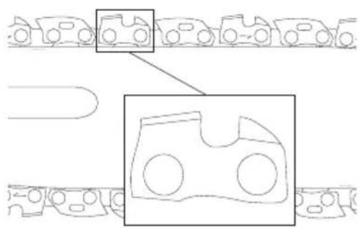
- Place the new chain in the slot of the guide bar, making sure the saw teeth are facing the correct direction by matching the arrow and graphic of the saw chain on the chain assembly cover 7 shown in Fig. G.
- Follow instructions for Installing the Guide Bar and Saw Chain.
Replacement chain and bar are available from your nearest authorized service center.
The DCMPS520 requires replacement 8" (203 mm) chain DT20693. Replacement 8" (203 mm) bar DT20694.
Saw Chain and Guide Bar Oiling (Fig. A)
Auto Oiling System
This pruner is equipped with an auto oiling system that keeps the saw chain and guide bar constantly lubricated.
- The oil level indicator 10 shows the level of the oil in the pruner. If the oil level is less than a quarter full, remove the battery from the pruner and refill the oil tank with the correct type of oil.
- Always empty oil tank when finished cutting.
- Always empty oil tank before storing this unit.
NOTE: Do not operate this pruner without oil.
NOTE: Always use a high-quality, biodegradable bar and chain oil for proper saw chain and bar lubrication. When pruning trees, vegetable-based bar and chain oil is recommended, as mineral-based oils may harm living trees. Never use dirty, used, or contaminated oil. Doing so may damage the tool.
Filling the Oil Reservoir
- Unscrew counterclockwise and then remove the oil cap 11. Fill the reservoir with the recommended bar and chain oil until the oil level has reached the top of the oil level indicator 10.
- Refit the oil cap and tighten clockwise.
- Periodically switch the pruner off and check the oil level indicator to ensure the bar and chain are being properly oiled.
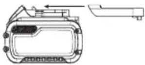
Guide Bar Cover and Wrench Storage (Fig. A, H–J)
The guide bar cover 12 has two functions, to cover the guide bar 4 when the tool is not in use and to store the wrench 13.
Guide Bar Cover
- To open the guide bar cover 12, lift up on the latch 25 and pull the two halves apart.
- Fit the guide bar cover 12 onto the guide bar 4 as shown in Fig. A, H–J. Ensure that the retaining pin 29 on the guide bar cover 12 aligns with the retaining hole 30 on the guide bar 4.
- To close the guide bar cover 12, close the two halves and ensure the latch 25 is secured to the notch 26.
Wrench
- Open the guide bar cover 12 to gain access to the wrench 13.
- Remove the wrench 13 by lifting the wrench end up and away from the guide bar cover.
- Store the wrench in the guide bar cover when finished. First install flat screwdriver end of the wrench into the retaining slot 27 and then press the wrench end down until the retaining clips 28 firmly secure the wrench 13 in place.
Bar Tip Guard (Fig. A)
WARNING: Never operate the pruner without the kick-up guard properly mounted on the guide bar to prevent rotational kickback.
The bar tip guard 6 reduces the chance of the saw chain 5 at the end of the guide bar 4 from coming into contact with objects which may cause the bar and saw chain to kickback towards the operator. In addition to reducing the chance of kickback, the bar tip guard 6 will reduce the chance of the chain from touching the ground.
Transporting Pruner (Fig. A, I)
- Always turn unit off, remove the battery and cover the guide bar 4 with the guide bar cover 12 when transporting the pruner.
OPERATION
Instructions for Use
WARNING: Always observe the safety instructions and applicable regulations.
WARNING: To reduce the risk of serious personal injury, turn tool off and disconnect battery pack before making any adjustments or removing/installing attachments or accessories. An accidental start-up can cause injury.
Proper Hand Position (Fig. A, K)
WARNING: To reduce the risk of serious personal injury, ALWAYS use proper hand position as shown.
WARNING: To reduce the risk of serious personal injury, ALWAYS hold securely in anticipation of a sudden reaction.
Proper hand position requires the left hand on the front handle 15, under the front hand guard 3, with the right hand on the rear handle 14.
NOTE: DO NOT hold the saw by the front hand guard 3.
Operating the Pruner (Fig. A)
WARNING: Read and understand all instructions. Failure to follow all instructions listed below may result in electric shock, fire and/or serious personal injury.
- Guard Against Kickback which can result in severe injury or death. See Important Safety Instructions Causes and Operator Prevention of Kickback, to avoid the risk of kickback.
- Do not overreach. Do not cut above chest height. Make sure your footing is firm. Keep feet apart. Divide your weight evenly on both feet.
- Use a firm grip with your left hand on the front handle 15 and your right hand on the rear handle 14 so that your body is to the left of the guide bar.
WARNING: Do not hold pruner by front hand guard. Keep elbow of left arm locked so that left arm is straight to withstand a kickback.
WARNING: Never use a cross-handed grip (left hand on the left handle and right hand on the front handle).
WARNING: Never allow any part of your body to be in line with the guide bar when operating the pruner.
- Never operate pruner while in a tree, in any awkward position or on a ladder or other unstable surface. You may lose control of pruner causing severe injury.
- Keep the pruner running at full speed the entire time you are cutting.
- Allow the chain to cut for you. Exert only light pressure. Do not put pressure on pruner at end of cut.
WARNING: When not in use always have the chain broke (if equipped) engaged, unit turned off and remove the battery pack.
WARNING: Never operate the pruner without the lap guard properly mounted on the guide bar to prevent rotational kickback.
ON/OFF Switch (Fig. A)
WARNING: Never attempt to lock a switch in the Ciposition.
Always be sure of your footing and grip the pruner firmly with both hands with the thumb and fingers encircling both handles.
- To turn the unit on, push down on the lock-off lever 2, shown in Fig. A, and squeeze the trigger switch 1. Once the unit is running, you may release the lock-off lever.
- To keep the unit running you must continue to squeeze the trigger switch 1.
- To turn the unit off, release the trigger switch 1.
NOTE: If too much force is applied while making a cut the pruner will turn off. To restart pruner, you must release the lock-off lever 2 and the trigger switch 1 before the pruner will restart. Begin your cut again, this time with less force. Allow the pruner to cut at its own pace.
Common Cutting Techniques
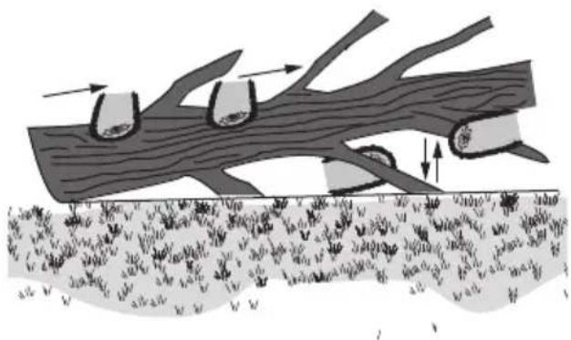
Limbing
Removing the branches from a fallen tree. When limbing, leave larger lower limbs to support the log off the ground. Remove the small limbs in one cut. Branches under tension should be cut from the bottom of the branch towards the top to avoid binding the pruner as shown below. Trim limbs from opposite side keeping tree stem between you and pruner. Never make cuts with pruner between your legs or straddle the limb to be cut.
natural_image
Diagram of a tree trunk with leaves and roots, showing movement arrows and soil layers (no text or symbols)Bucking
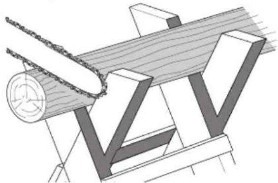
WARNING: Recommend that first-time users should practice cutting on a pruner horse.
Cutting a felled tree or log into lengths. How you should cut depends on how the log is supported. Use a saw horse whenever possible as shown below.
natural_image
Technical illustration of a wooden log being cut with chains, showing grain and structural components (no text or symbols)- Always start a cut with the pruner chain running at full speed.
- Place the ribbed bumper 21 of the pruner behind the area of the initial cut as shown below.
- Turn the pruner on then rotate the pruner chain and bar down into the tree, using the ribbed bumper as a hinge.
-
Once the pruner gets to a 45^ angle, level the pruner again and repeat steps until you cut fully through.
-
When the tree is supported along its entire length, make a cut from the top (overbuck), but avoid cutting the earth as this will dull your pruner quickly.

- When supported at one end first, cut 1/3 the diameter from the underside (underbuck). Then make the finishing cut by overbucking to meet the first cut as shown below.
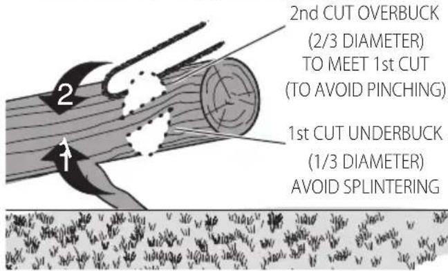
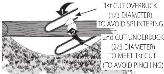
- When supported at both ends. First, cut 1/3 down from the top overbuck. Then make the finished cut by underbucking the lower 2/3 to meet the first cut as shown below.
- When on a slope always stand on the uphill side of the log. When "cutting through," to maintain complete control reduce the cutting pressure near the end of the cut without relaxing your grip on the pruner handles. Don't let the chain contact the ground. After completing the cut, wait for the pruner chain to stop before you move the pruner. Always stop the motor before moving from cut to cut.
MAINTENANCE
Your power tool has been designed to operate over a long period of time with a minimum of maintenance. Continuous satisfactory operation depends upon proper tool care and regular cleaning.
WARNING: To reduce the risk of serious personal injury, turn tool off and disconnect battery pack before making any adjustments or removing/
installing attachments or accessories. An accidental start-up can cause injury.
The charger and battery pack are not serviceable.
Lubrication
Refer to Auto Oiling System described in the Saw Chain and Guide Bar Oiling section.
Cleaning
WARNING: Electrical shock and mechanical hazard. Disconnect the electrical appliance from the power source before cleaning.
WARNING: To ensure safe and efficient operation, always keep the electrical appliance and the ventilation slots clean.
WARNING: Never use solvents or other harsh chemicals for cleaning the non-metallic parts of the tool. These chemicals may weaken the materials used in these parts. Use a cloth dampened only with water and mild soap. Never let any liquid get inside the tool; never immerse any part of the tool into a liquid.
Ventilation slots can be cleaned using a dry, soft non-metallic brush and/or a suitable vacuum cleaner. Do not use water or any cleaning solutions. Wear approved eye protection and an approved dust mask.
Saw Chain and Guide Bar
After every few hours of use, remove the chain assembly cover, guide bar and saw chain and clean thoroughly using a soft bristle brush. Ensure oiling hole on bar is clear of debris.
Sprocket and Chain Assembly Cover
(Fig. A, C-G)
CAUTION: Sharp chain. Always wear protective gloves v e handling the saw chain. The saw chain is sharp and can cut you when it is not running.
WARNING: Sharp moving chain. To prevent accidental operation, ensure the battery is removed from the tool before performing the following operations. Failure to do this could result in serious personal injury.
- Place the saw on a flat, firm surface.
- Remove chain assembly cover 7 as described in Installing the Guide Bar and Saw Chain section.
- Wearing protective gloves, use a clean, soft bristle brush to wipe away any saw dust, sticks, vines or other debris that may have collected inside the chain assembly cover 7 and around the saw chain 5 or sprocket 22.
- Rotate the chain tensioning screw 9 using the flat screwdriver end of the wrench 13. Turning the screw counterclockwise allows the guide bar 4 to recede and reduces the tension on the chain so that it may be removed.
- Wearing protective gloves, grasp the saw chain and guide bar and lift them away from the tool.
-
Wearing protective gloves, use a clean, soft bristle brush to wipe away any saw dust or other debris that may have collected on the guide bar 4 and around the saw chain 5.
-
Install the chain, guide bar and chain assembly cover 7 as described in Installing the Guide Bar and Saw Chain, Replacing the Saw Chain sections and adjust chain tension properly before use as described in the Adjusting Chain Tension section.
Optional Accessories
WARNING: Since accessories, other than those offered by DEWALT, have not been tested with this product, use of such accessories with this tool could be hazardous. To reduce the risk of injury, only DEWALT-recommended accessories should be used with this product.
Consult your dealer for further information on the appropriate accessories.
Saw Chain Sharpening (Fig. L–N)
CAUTION: Sharp chain. Always wear protective gloves when handling the chain. The chain is sharp and can cut you when it is not running.
WARNING: Sharp moving chain. To prevent accidental operation, ensure that battery is removed from the tool before performing the following operations. Failure to do this could result in serious personal injury.
WARNING: Do not over file chain rakers, this will increase the risk of kickback. If the chain has been sharpened more than four times, replace it.
Each time the chain is sharpened, it loses some of the low kickback qualities and extra caution should be used. It is recommended that a saw chain be sharpened no more than four times.
nOTE: The cutters will dull immediately if they touch the ground/dirt or a nail while cutting.
To get the best possible performance from your pruner it is important to keep the teeth of the saw chain sharp. Follow these helpful tips for proper saw chain sharpening:
- For best results use a 11/64" (4.5 mm) file and a file holder or filing guide to sharpen your saw chain. This will ensure you always get the correct sharpening angles.
- Place the file holder flat on the top plate and depth gauge of the cutter.
- Keep the correct top plate 23 filing angle line of 30^ on your file guide parallel with your chain (file at 60^ from chain viewed from the side) as shown in Fig. L.
- Sharpen cutters on one side of the chain first. File from the inside of each cutter to the outside. Then turn your saw around and repeat the processes (2, 3, 4) for cutters on the other side of the chain.
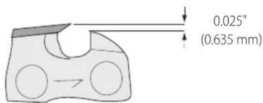
NOTE: Use a flat file to file the tops of the rakers (portion of chain link in front of the cutter) so they are about 0.025" (0.635 mm) below the tips of the cutters as shown in Fig. M.
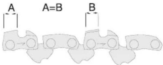
- Keep all cutter lengths equal as shown in Fig. N.
- If damage is present on the chrome surface of the top plates or side plates, file back until such damage is removed.
CAUTION: After filing, the cutter will be sharp, so use extra radiation during this process.
Protecting the Environment
Separate collection. Products and batteries marked with this symbol must not be disposed of with normal household waste.
■ Products and batteries contain materials that can be recovered or recycled, reducing the demand for raw materials. Please recycle electrical products and batteries according to local provisions. Further information is available at www.2helpU.com.
Rechargeable Battery Pack
This long-life battery pack must be recharged when it fails to produce sufficient power on jobs that were easily done before. At the end of its technical life, discard it with due care for our environment:
- Run the battery pack down completely, then remove it from the tool.
- Li-Ion cells are recyclable. Take them to your dealer or a local recycling station. The collected battery packs will be recycled or disposed of properly.
natural_image
Technical line drawing of a mechanical device with no visible text or symbolsnatural_image
Diagram of a tree trunk with leaves and roots, showing movement arrows and soil layers (no text or symbols)Tronzado
natural_image
Technical illustration of a mechanical assembly with a chain and wooden beam (no text or symbols)natural_image
Technical line drawing of a mechanical component with no visible text or symbolsnatural_image
Diagram of a tree trunk with two circular structures and directional arrows indicating movement or flow (no text or symbols)Tronçonnage
natural_image
Technical illustration of a wooden log being cut with chains, showing grain and support structure (no text or symbols)Bloc-batterie rechargeable
natural_image
Technical line drawing of a mechanical device with no visible text or symbolsnatural_image
Diagram of a tree trunk with roots and leaves, showing movement arrows and soil layers (no text or symbols)natural_image
Technical illustration of a mechanical assembly with wooden beams and a circular component (no text or symbols)2° TAGLIO DALL'ALTO (OVERBUCK) (2/3 DEL DIAMETRO) IN MODO DA INCONTRARE IL 1° TAGLIO (ED EVITARE CHE LA LAMA RIMANGA INCASTRATA)
Vice-President Engineering, PTE- Europe
natural_image
Technical line drawing of a mechanical component with no visible text or symbolsnatural_image
Diagram of a tree trunk with embedded soil layers and directional arrows indicating movement (no text or symbols)natural_image
Technical illustration of a wooden beam with a circular cutterhead and meshing, showing no text or symbolsGodkjenningsinstansnr. (Notified Body number): 0366
ID nummer: 40056737
2000/14/EU, vedlegg V
L_WA (målt lydeffekt) 96 dB(A)
L_WA (garantert lydeffekt) 99 dB(A)
Disse produktene er også i samsvar med direktiv 2014/30/EU og 2011/65/EU. For mer informasjon, kontakt DEWALT på følgende adresse eller se baksiden av bruksanvisningen.
Vice-President Engineering, PTE-Europe
natural_image
Technical line drawing of a mechanical component with no visible text or symbolsFor eksempel kan
natural_image
Diagram of tree bark with embedded soil layers and arrows indicating flow or movement (no text or symbols)Kubbing
natural_image
Technical illustration of a mechanical assembly with a pulley and wooden beam (no text or symbols)- KUTT OVERHENG (1/3 DIAMETER) FOR Å UNNGÅ SPLINTER
2 KUTT UNDERHENG (2/3 DIAMETER) FOR Å M∅TE 1. KUTT (FOR Å UNNGÅ KNIPING AV BLADET)
natural_image
Technical line drawing of a mechanical device with no visible text or symbolsnatural_image
Diagram of a tree trunk with leaves and soil layers, showing directional arrows indicating movement (no text or labels)Corte transversal do tronco
natural_image
Technical line drawing of a mechanical assembly with a pulley and wooden frame (no text or symbols)natural_image
Technical line drawing of a mechanical component with no visible text or symbolsnatural_image
Diagram of a tree trunk with arrows indicating flow or movement, showing grass at the base and leaves growing from the trunk (no text or symbols present)Pölkytys
natural_image
Technical illustration of a mechanical assembly with wooden beams and a circular component (no text or symbols)-
SAHAUSKERTA ALAPÖLKITYS (1/3 HALKAISIJA) HAJOAMISEN VÄLTTÄMISEKSI
-
SAHAUSKERTA ALAPÖLKITYS (2/3 HALKAISIJA)
- SAHAUSKOHTAAN (PURISTUMISEN VÄLTTÄMISEKSI)
Vice-President Engineering, PTE-Europe
natural_image
Technical line drawing of a device casing with mounting bracket and side panel (no text or symbols)natural_image
Diagram of tree bark with embedded soil layers and arrows indicating flow or movement (no text or symbols)Kapning
natural_image
Technical illustration of a wooden cutting machine with a chain and roller, showing wood grain and structural components (no text or symbols)natural_image
Technical line drawing of a mechanical component with no visible text or symbolsnatural_image
Diagram of a tree trunk with two hanging blocks and directional arrows indicating movement or force (no text or symbols)Kütüklere ayırmak
natural_image
Technical line drawing of a mechanical assembly with wooden beams and a circular component (no text or symbols)natural_image
Technical line drawing of a mechanical device with no visible text or symbolsnatural_image
Diagram of tree bark with roots and leaves, showing erosion or growth processes (no text or labels)Τεμαχισμός
natural_image
Technical illustration of a mechanical assembly with wooden beams and a circular component (no text or symbols)
- 18V BESKÆRINGSSAV
- DCMPS520
- Tillykke!
- Opskæring
- Ablängen
- EC-Declaration of Conformity
- Machinery Directive
- Pruner Saw
- DECLARATION OF CONFORMITY THE SUPPLY OF MACHINERY (SAFETY) REGULATIONS 2008
- Definitions: Safety Guidelines
- GENERAL POWER TOOL SAFETY WARNINGS
- SAVE ALL WARNINGS AND INSTRUCTIONS FOR FUTURE REFERENCE
- 1) Work Area Safety
- 2) Electrical Safety
- 3) Personal Safety
- 4) Power Tool Use and Care
- 5) Battery Tool Use and Care
- 6) Service
- Pruner Safety Warnings
- Causes and Operator Prevention of Kickback:
- The Following Precautions Should Be Followed to Minimize Kickback:
- Kickback Safety Features
- Pruner Names and Terms
- Residual Risks
- SAVE THESE INSTRUCTIONS
- Chargers
- Electrical Safety
- Mains Plug Replacement (U.K. & Ireland Only)
- Using an Extension Cable
- Important Safety Instructions for All Battery Chargers
- Charging a Battery (Fig. B)
- Hot/Cold Pack Delay
- Electronic Protection System
- Wall Mounting
- Charger Cleaning Instructions
- Battery Packs
- Important Safety Instructions for All Battery Packs
- READ ALL INSTRUCTIONS
- Transportation
- Transporting the FLEXVOLT™ Battery
- Storage Recommendations
- Labels on Charger and Battery Pack
- Battery Type
- Package Contents
- Markings on Tool
- Date Code Position (Fig. A)
- Description (Fig. A)
- Intended Use
- ASSEMBLY AND ADJUSTMENTS
- Inserting and Removing the Battery Pack from the Tool (Fig. B)
- To Install the Battery Pack into the Tool Handle
- To Remove the Battery Pack from the Tool
- Fuel Gauge Battery Packs (Fig. B)
- Installing the Guide Bar and Saw Chain (Fig. A, C–G)
- Adjusting Chain Tension (Fig. A, C–F)
- Replacing the Saw Chain (Fig. A, C–G)
- Replacement chain and bar are available from your nearest authorized service center.
- Saw Chain and Guide Bar Oiling (Fig. A)
- Auto Oiling System
- Filling the Oil Reservoir
- Guide Bar Cover and Wrench Storage (Fig. A, H–J)
- Guide Bar Cover
- Wrench
- Bar Tip Guard (Fig. A)
- Transporting Pruner (Fig. A, I)
- OPERATION
- Instructions for Use
- Proper Hand Position (Fig. A, K)
- Operating the Pruner (Fig. A)
- ON/OFF Switch (Fig. A)
- Common Cutting Techniques
- Limbing
- Bucking
- MAINTENANCE
- Lubrication
- Cleaning
- Saw Chain and Guide Bar
- Sprocket and Chain Assembly Cover
- (Fig. A, C-G)
- Optional Accessories
- Saw Chain Sharpening (Fig. L–N)
- Protecting the Environment
- Rechargeable Battery Pack
- Tronzado
- Tronçonnage
- Bloc-batterie rechargeable
- Kubbing
- Corte transversal do tronco
- Pölkytys
- Kapning
- Kütüklere ayırmak
- Τεμαχισμός
Brand : DEWALT
Model : DCMPS520
Category : Saw