DW702 - Saw DEWALT - Free user manual and instructions
Find the device manual for free DW702 DEWALT in PDF.

User questions about DW702 DEWALT
0 question about this device. Answer the ones you know or ask your own.
Ask a new question about this device
Download the instructions for your Saw in PDF format for free! Find your manual DW702 - DEWALT and take your electronic device back in hand. On this page are published all the documents necessary for the use of your device. DW702 by DEWALT.
USER MANUAL DW702 DEWALT
natural_image
Technical line drawing of a mechanical clamp or bracket with two parallel rods and a central mounting bracket (no text or symbols)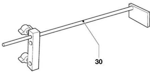
natural_image
Technical line drawing of a mechanical lever or support structure with a labeled dimension (30), no text or symbols present.A4
A3
natural_image
Technical line drawing of a mechanical device with two vertical rods and a central cylindrical component (no text or symbols)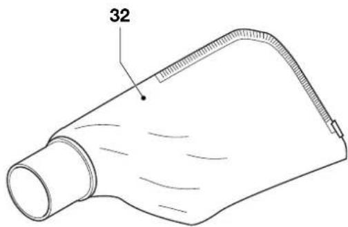
natural_image
Line drawing of a conical object with a pointed tip and label '32' (no text or symbols on the object itself)A5
A6
text_image
Technical diagram of a mechanical device with numbered parts and an inset view showing component details.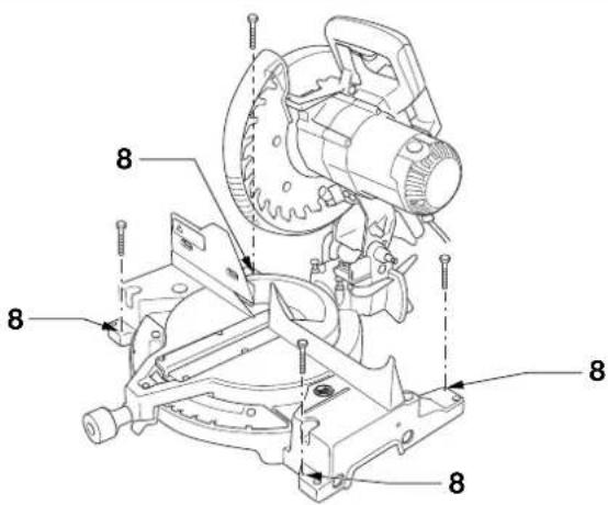
text_image
Technical diagram of a mechanical assembly with numbered parts and alignment markersB
C
text_image
10 2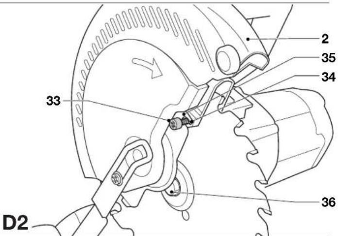
text_image
2 35 34 33 36 D2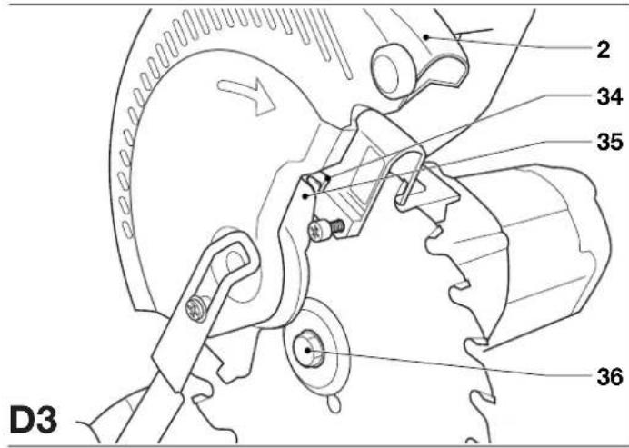
text_image
D3 2 34 35 36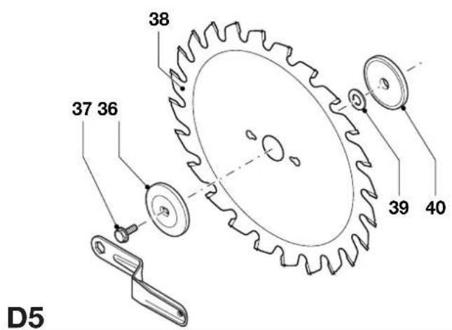
text_image
38 37 36 39 40 D5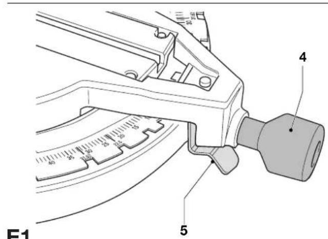
text_image
F1 4 5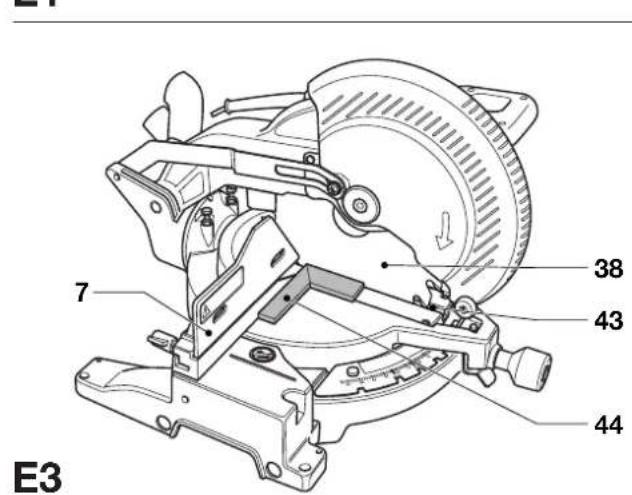
text_image
E3 7 38 43 44 E3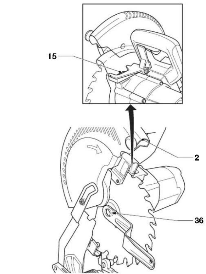
text_image
15 2 36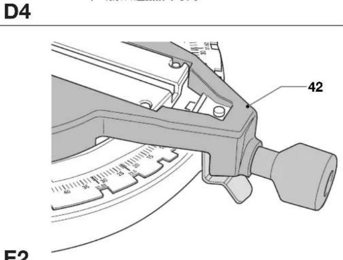
text_image
D4 42 F2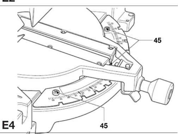
text_image
E4 45 45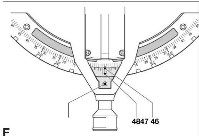
text_image
80 35 40 35 25 20 15 10 5 7 5 15 20 25 30 35 40 45 50 F 4847 46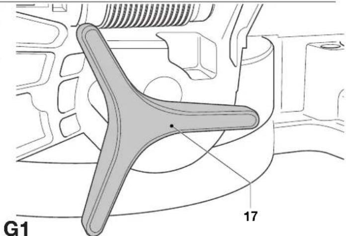
text_image
G1 17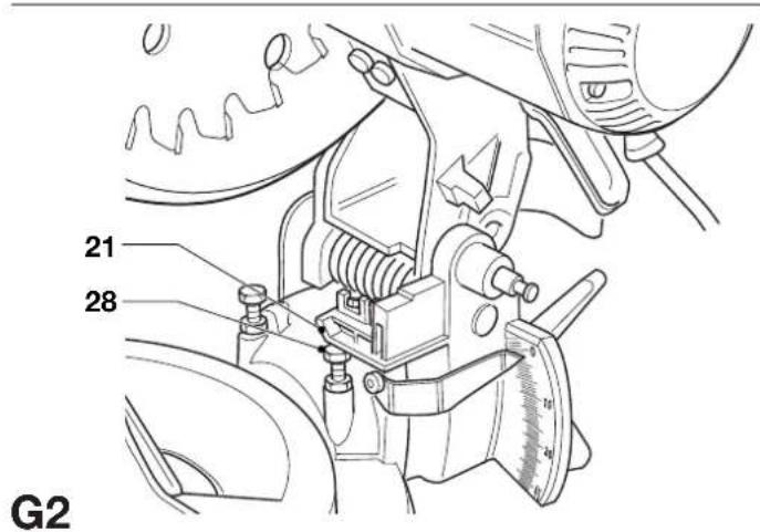
text_image
21 28 G2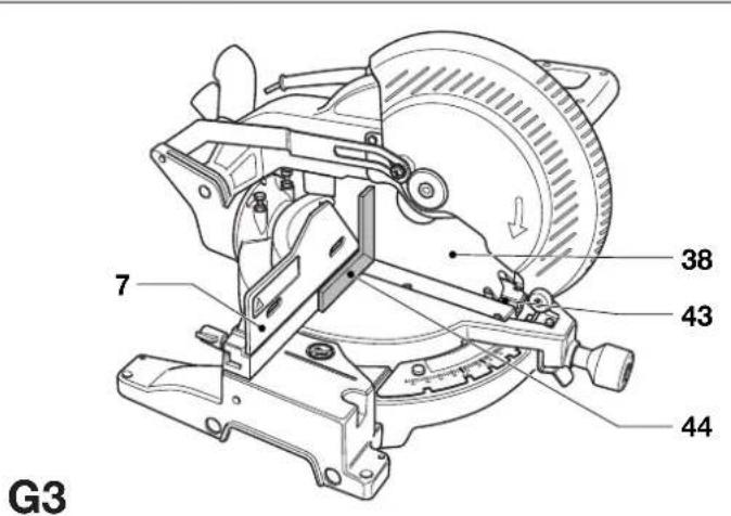
text_image
7 38 43 44 G3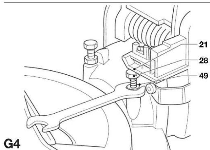
text_image
21 28 49 G4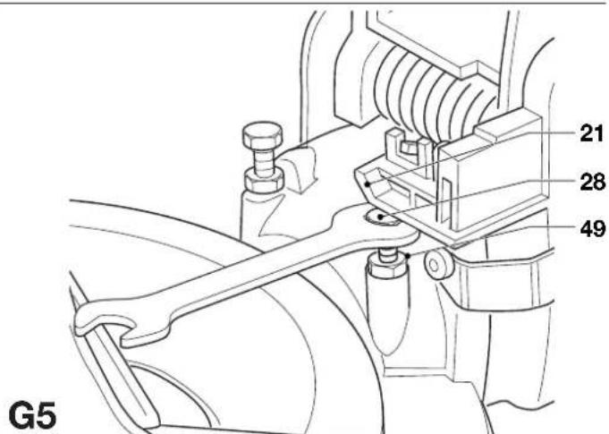
text_image
21 28 49 G5
text_image
G6 51 1250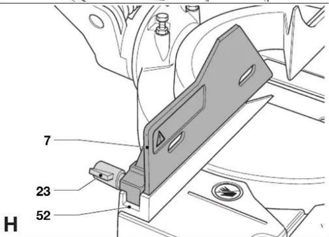
text_image
7 23 52 H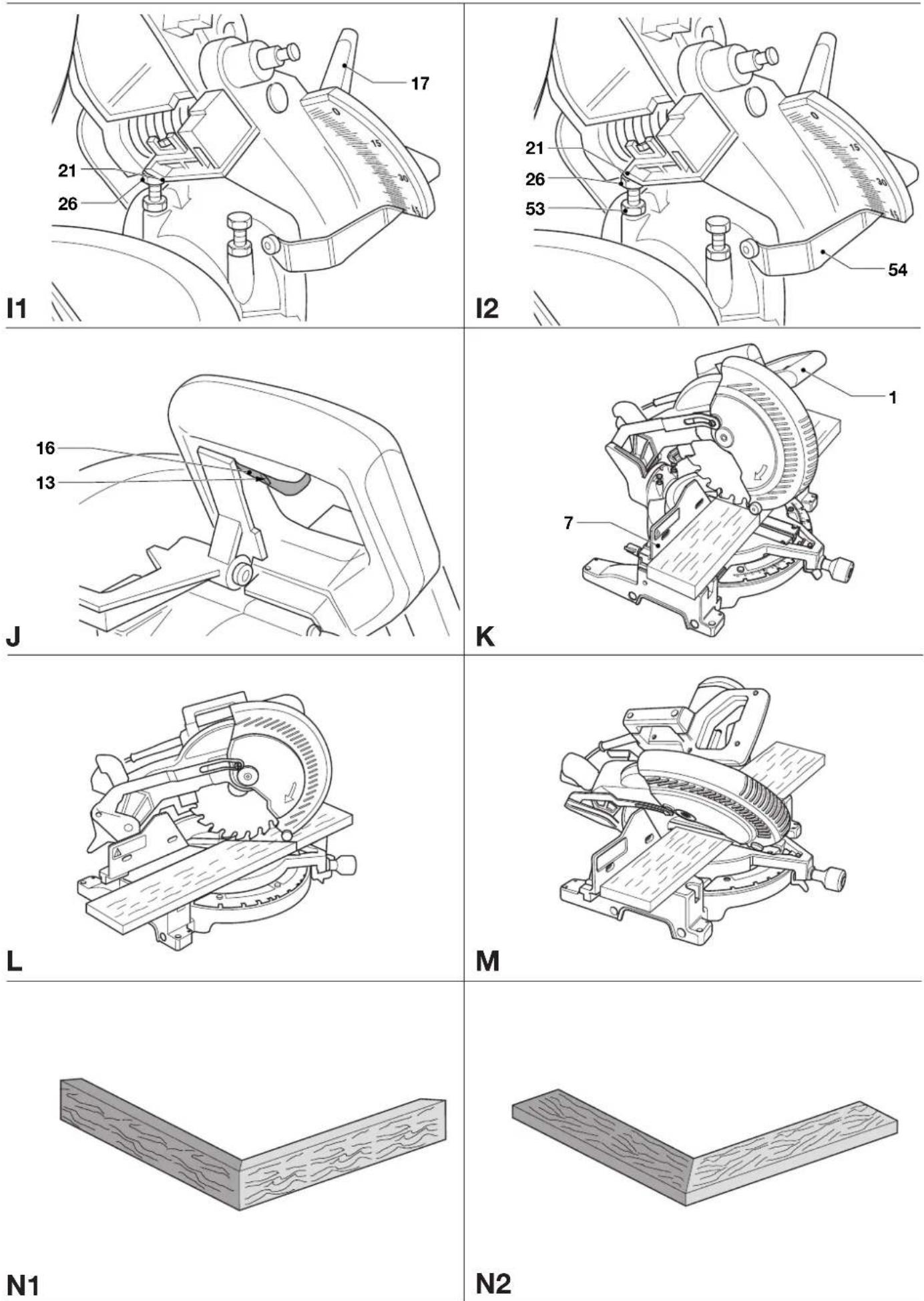
natural_image
Line drawing of a wooden box with visible grain patterns (no text or symbols)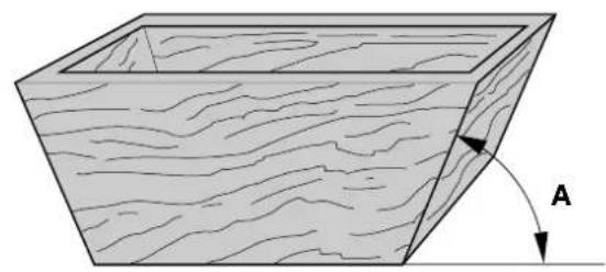
natural_image
Diagram of a rectangular wooden plank with visible grain patterns and an arrow labeled 'A' indicating direction (no text or symbols beyond label)01
text_image
25 22.5 20 15 5 5 15 20 22.5 P102

text_image
P2P1
text_image
0 5 10 20 25 30 22.5 1/2 40 45 P3GERINGSSAV DW702/DW703
Tillykke!
Product and Safety GmbH (TRPS)
Am Grauen Stein 1
D-51105 Köln
Germany
| Cert. No. | |
| AM2110437.01 |
line
| INDSTIL DENNE SMIGVINKEL PÅ SAVEN | KVADRATISK KASSE | 6-SIDET KASSE | 8-SIDET KASSE | | --------------------------------- | ---------------- | ------------- | ------------- | | 0.5 | 45 | 30 | 20 | | 1.0 | 44 | 28 | 18 | | 1.5 | 43 | 26 | 16 | | 2.0 | 42 | 24 | 14 | | 2.5 | 41 | 22 | 12 | | 3.0 | 40 | 20 | 10 | | 3.5 | 39 | 18 | 8 | | 4.0 | 38 | 16 | 6 | | 4.5 | 37 | 14 | 5 | | 5.0 | 36 | 12 | 5 | | 5.5 | 35 | 10 | 5 | | 6.0 | 34 | 8 | 5 | | 6.5 | 33 | 6 | 5 | | 7.0 | 32 | 5 | 5 | | 7.5 | 31 | 5 | 5 | | 8.0 | 30 | 5 | 5 | | 8.5 | 29 | 5 | 5 | | 9.0 | 28 | 5 | 5 | | 9.5 | 27 | 5 | 5 | | 10.0 | 26 | 5 | 5 | | 10.5 | 25 | 5 | 5 | | 11.0 | 24 | 5 | 5 | | 11.5 | 23 | 5 | 5 | | 12.0 | 22 | 5 | 5 | | 12.5 | 21 | 5 | 5 | | 13.0 | 20 | 5 | 5 | | 13.5 | 19 | 5 | 5 | | 14.0 | 18 | 5 | 5 | | 14.5 | 17 | 5 | 5 | | 15.0 | 16 | 5 | 5 | | 15.5 | 15 | 5 | 5 | | 16.0 | 14 | 5 | 5 | | 16.5 | 13 | 5 | 5 | | 17.0 | 12 | 5 | 5 | | 17.5 | 11 | 5 | 5 | | 18.0 | 10 | 5 | 5 | | 18.5 | 9 | 5 | 5 | | 19.0 | 8 | 5 | 5 | | 19.5 | 7 | 5 | 5 | | 20.0 | 6 | 5 | 5 | | 20.5 | 5 | 5 | 5 | | Note: The data is extracted from the provided image and presented in CSV format as requested by the code. The numbers above the data points are not explicitly provided in the code format for the original data series. The actual data points may vary due to the use of random number generation or sampling. There is only one data series represented by the original series.Mikrometerskala (fig. P1 - P3)
- Slå geringssaven fra (off).
Product and Safety GmbH (TRPS)
Am Grauen Stein 1
D-51105 Köln
Germany
Zertifikat-Nr.
AM2110437.01
Sicherheitshinweise
You have chosen a DeWALT power tool. Years of experience, thorough product development and innovation make DeWALT one of the most reliable partners for professional power tool users.
Technical data
| DW702 DW703 | ||
| Voltage V 230 230 | ||
| (U.K. & Ireland only) V 230/115 | ||
| Power input W 1,600 1,600 | ||
| Blade diameter mm 250 250 | ||
| Blade bore mm 30 30 | ||
| Max. blade speed min | -1 | 5,000 5,000 |
| Max. cross-cut capacity 90° mm 162 162 | ||
| Max. mitre capacity 45° mm 114 114 | ||
| Max. depth of cut 90° mm 90 90 | ||
| Max. depth of bevel cross-cut 45° | mm - | 58 |
| Mitre (max. positions) | left 50° | 50° |
| right 50° | 50° | |
| Bevel (max. positions) | left - | 48° |
| right - | 3° | |
| 0° mitre | ||
| Resulting width at max. height 89 mm | mm 95 95 | |
| Resulting height at max. width 162 mm | mm 41 41 | |
| 45° mitre | ||
| Resulting width at max. height 89 mm | mm 67 | 67 |
| Resulting height at max. width 114 mm | mm 41 41 | |
| 45° bevel | ||
| Resulting width at max. height 61mm | mm - | 95 |
| Resulting height at max. width 161 mm | mm - | 25 |
| 31.62° mitre, 33.85° bevel | ||
| Resulting height at max. width 133 mm | mm - | 20 |
| Automatic blade brake time | s < 10.0 | < 10.0 |
| Weight | kg 14.8 | 13.8 |
| Fuses: | ||
| Europe | 230 V tools | 10 Amperes, mains |
| U.K. & Ireland | 230 V tools | 13 Amperes, in plugs |
The following symbols are used throughout this manual:

Denotes risk of personal injury, loss of life or damage to the tool in case of non-observance of the instructions in this manual.

Denotes risk of electric shock.
EC-Declaration of conformity

DW702/DW703
DeWALT declares that these Power Tools have been designed in compliance with: 98/37/EEC, 89/336/EEC, EN 55014-2, EN 55014, EN 61000-3-2, EN 61000-3-3 & EN 61029.
For more information, please contact DEWALT at the address below or refer to the back of the manual.
| DW702 | DW703 | ||||
| L_pa | (sound pressure) | dB(A)* | 88.8 | 88.8 | |
| L_wa | (acoustic power) dB(A) | 101.7 | 101.7 | ||
| Weighted RMS acceleration value | m/s2 | < 2.5 m/s2 | < 2.5 m/s2 | ||
* at the operator's ear
Director Engineering and Product Development Horst Großmann

text_image
X. fopsmannProduct and Safety GmbH (TRPS)
Am Grauen Stein 1
D-51105 Köln
Germany
| Cert. No. | |
| AM2110437.01 |
Safety instructions
When using stationary power tools, always observe the safety regulations applicable in your country to reduce the risk of fire, electric shock and personal injury. Read all of this manual carefully before operating the tool. Save this manual for future reference.
General
1 Keep work area clean
Cluttered areas and benches can cause accidents.
2 Consider work area environment
Do not expose the tool to rain. Do not use the tool in damp or wet conditions. Keep the work area well lit (250 - 300 Lux). Do not use the tool where there is a risk of causing fire or explosion, e.g. in the presence of flammable liquids and gases.
3 Keep children away
Do not allow children, visitors or animals to come near the work area or to touch the tool or the mains cable.
4 Dress properly
Do not wear loose clothing or jewellery, as these can be caught in moving parts. Wear protective hair covering to keep long hair out of the way. When working outdoors, preferably wear suitable gloves and non-slip footwear.
5 Personal protection
Always use safety glasses. Use a face or dust mask whenever the operations may produce dust or flying particles. If these particles might be considerably hot, also wear a heat-resistant apron. Wear ear protection whenever the sound level seems uncomfortable, i.e. if the sound pressure stated in this manual exceeds 85 dB(A).
6 Guard against electric shock
Prevent body contact with earthed or surfaces (e.g. pipes, radiators, cookers and refrigerators). When using the tool under extreme conditions (e.g. high humidity, when metal swarf is being produced, etc.), electric safety can be improved by inserting an isolating transformer or a (FI) earth-leakage circuit-breaker.
7 Do not overreach
Keep proper footing and balance at all times.
8 Stay alert
Watch what you are doing. Use common sense. Do not operate the tool when you are tired.
9 Secure workpiece
Use clamps or a vice to hold the workpiece. It is safer and it frees both hands to operate the tool.
10 Connect dust extraction equipment
If devices are provided for the connection of dust extraction and collection facilities, ensure that these are connected and properly used.
11 Remove adjusting keys and wrenches
Always check that adjusting keys and wrenches are removed from the tool before operating the tool.
12 Extension cables
Before use, inspect the extension cable and replace if damaged. When using the tool outdoors, only use extension cables intended for outdoor use and marked accordingly.
13 Use appropriate tool
The intended use is described in this instruction manual. Do not force small tools or attachments to do the job of a heavy-duty tool. The tool will do the job better and safer at the rate for which it was intended. Do not force the tool.
Warning! The use of any accessory or attachment or performance of any operation with this tool other than those recommended in this instruction manual may present a risk of personal injury.
14 Check for damaged parts
Before use, carefully check the tool and mains cable for damage. Check for misalignment and seizure of moving parts, breakage of parts, damage to guards and switches and any other conditions that may affect its operation.
Ensure that the tool will operate properly and perform its intended function. Do not use the tool if any part is damaged or defective.
Do not use the tool if the switch does not turn it on and off. Have any damaged or defective parts replaced by an authorised DEWALT repair agent. Never attempt any repairs yourself.
15 Unplug tool
Switch off and wait for the tool to come to a complete standstill before leaving it unattended. Unplug the tool when not in use, before changing any parts of the tools, accessories or attachments and before servicing.
16 Avoid unintentional starting
Be sure that the tool is switched off before plugging in.
17 Do not abuse cord
Never pull the cord to disconnect from the socket. Keep the cord away from heat, oil and sharp edges.
18 Store idle tools
When not in use, tools must be stored in a dry place and locked up securely, out of reach of children.
19 Maintain tools with care
Keep the tools in good condition and clean for better and safer performance. Follow the instructions for maintenance and changing accessories. Keep all handles and switches dry, clean and free from oil and grease.
20 Repairs
This tool is in accordance with the relevant safety regulations. Have your tool repaired by an authorised DEWALT repair agent. Repairs should only be carried out by qualified persons using original spare parts; otherwise this may result in considerable danger to the user.
Additional safety rules for mitre saws
21 Guard actuation
The blade guard on your saw will automatically raise when the arm is brought down; it will lower over the blade when the arm is raised. The guard can be raised by hand when installing or removing saw blades or for inspection of the saw. Never raise the blade guard manually unless the saw is switched off.
22 Flying debris
The front section of the guard is louvred for visibility while cutting. Although the louvres dramatically reduce flying debris, there are openings in the guard and safety glasses should be worn at all times when viewing through the louvres.
23 Saw blades
Make sure that the blade rotates in the correct direction. Keep the blade sharp. Do not use blades of larger or smaller diameter than recommended. For the proper blade rating refer to the technical data.
24 Blade guards
Never operate the saw without the guards in place.
25 Mind your hands
Keep your hands out of the path of the saw blade. Never place them in the blade area when the saw is connected to the electrical power source.
26 Stopping the motor
Raise the blade from the kerf in the workpiece prior to releasing the switch. Never attempt to stop the machine in motion by jamming a tool or similar against the blade. Do not wedge anything against the fan to hold the motor shaft.
27 Maintenance of the blade and the arbor collars
Make sure that the blade and the arbor collars are clean on the surfaces of contact and use the supplied wrench to tighten.
Environmental temperature
Only use the machine at ambient temperatures from 5 °C to 40 °C.
Electrical safety
The electric motor has been designed for one voltage only. Always check that the power supply corresponds to the voltage on the rating plate.

Your tool is double insulated in accordance with EN 61029; therefore no earth wire is required.
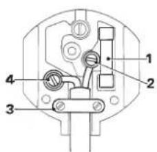
Mains plug replacement
(U.K. & Ireland only)
- Should your mains plug need replacing and you are competent to do this, proceed as instructed below. If you are in doubt, contact an authorized D≡WALT repair agent or a qualified electrician.
- Disconnect the plug from the supply.
- Cut off the plug and dispose of it safely; a plug with bared copper conductors is dangerous if engaged in a live socket outlet.
- Only fit 13 Amperes BS1363A approved plugs fitted with the correctly rated fuse (1).
- The cable wire colours, or a letter, will be marked at the connection points of most good quality plugs. Attach the wires to their respective points in the plug (see below). Brown is for Live (L) (2) and Blue is for Neutral (N) (4).
- Before replacing the top cover of the mains plug ensure that the cable restraint (3) is holding the outer sheath of the cable firmly and that the two leads are correctly fixed at the terminal screws.
text_image
Technical diagram of an electrical socket with numbered components for identification
Never use a light socket.
Never connect the live (L) or neutral (N) wires to the earth pin marked E or 12
For 115 V units with a power rating exceeding 1500 W, we recommend to fit a plug to BS4343 standard.
Using an extension cable
If an extension cable is required, use an approved extension cable suitable for the power input of this tool (see technical data). The minimum conductor size is 1.5 mm ^2 .
When using a cable reel, always unwind the cable completely. Also refer to the table below.
Conductor size (mm²) Cable rating (Amperes)
| 0.75 6 | |||||
| 1.00 10 | |||||
| 1.50 15 | |||||
| 2.50 20 | |||||
| 4.00 25 | |||||
| Cable length (m) | |||||
| 7.5 15 25 30 45 60 | |||||
| Voltage Amperes Cable rating (Amperes) | |||||
| 115 0 - 2.0 6 6 6 | 6 | 6 | 10 | ||
| 2.1 - 3.4 6 6 6 | 6 | 15 | 15 | ||
| 3.5 - 5.0 6 6 10 | 15 | 20 | 20 | ||
| 5.1 - 7.0 | 10 | 10 | 15 | 20 | 20 25 |
| 7.1 - 2.0 | 15 | 15 | 20 | 25 | - |
| 12.1 - 20.0 | 20 | 20 | 25 | - | - |
| 230 0 - 2.0 6 6 6 | 6 | 6 | 6 | ||
| 2.1 - 3.4 6 6 6 | 6 | 6 | 6 | 6 | |
| 3.5 - 5.0 6 6 6 | 6 | 10 | 15 | ||
| 5.1 - 7.0 | 10 | 10 | 10 | 15 | 15 |
| 7.1 - 12.0 | 15 | 15 | 15 | 15 | 20 20 |
| 12.1 - 20.0 | 20 | 20 | 20 | 20 | 25 |
Voltage drops
Inrush currents cause short-time voltage drops. Under unfavourable power supply conditions, other equipment may be affected.
If the system impedance of the power supply is lower than 0.25 Ω, disturbances are unlikely to occur.
Package contents
The package contains:
1 Assembled mitre saw
1 Blade spanner
1 Saw blade, ATB (DW703)
1 Saw blade, TCG (DW702)
2 Clamps (DW702)
1 Instruction manual
1 Exploded drawing
- Check for damage to the tool, parts or accessories which may have occurred during transport.
• Take the time to thoroughly read and understand this manual prior to operation.
Description (fig. A1 - A6)
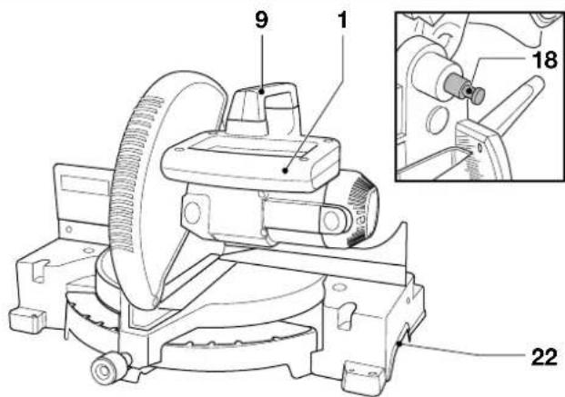
A1
1 Operating handle
2 Moveable lower guard
3 Fence right-hand side
4 Mitre clamp knob
5 Mitre latch
6 Mitre scale
7 Fence left-hand side
8 Bench mounting holes
9 Carrying handle
10 Head lock up release lever
11 Rear lower guard
12 Bevel scale
13 Padlock hole
14 Blade spanner
15 Spindle lock button
16 Trigger switch
17 Bevel clamp handle
18 Head lock down pin
A2
20 Dust spout
21 Angle position stop
22 Hand indentation
23 Upper fence left-hand side clamping knob
24 Upper guard
25 Motor housing
26 Bevel position adjustment stop
27 Kerf plate
28 Vertical position adjustment stop
A3
29 Work support extension
A4
30 Adjustable length stop
A5
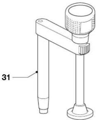
31 Work piece clamp
A6
32 Dustbag
Assembly

Prior to assembly always unplug the tool.
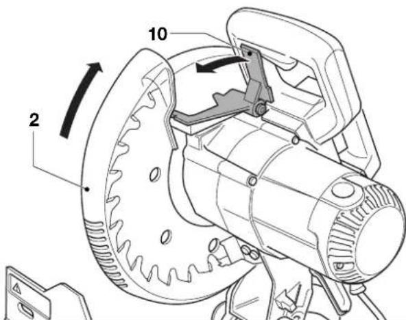
Unpacking (fig. B)
- Remove the saw from the packing material carefully using the carrying handle (9).
- Press down the operating handle (1) and pull out the lock down pin (18), as shown.
- Gently release the downward pressure and allow the arm to rise to its full height.
Bench mounting (fig. C)
- Holes (8) are provided in all four feet to facilitate bench mounting. Two different sized holes are provided to accommodate different sizes of bolts. Use either hole; it is not necessary to use both. Always mount your saw firmly to prevent movement. To enhance the portability, the tool can be mounted to a piece of 12.5mm or thicker plywood which can then be clamped to your work support or moved to other job sites and reclamped.
- When mounting your saw to a piece of plywood, make sure that the mounting screws do not protrude from the bottom of the wood. The plywood must sit flush on the work support. When clamping the saw to any work surface, clamp only on the clamping bosses where the mounting screw holes are located. Clamping at any other point will interfere with the proper operation of the saw.
- To prevent binding and inaccuracy, be sure the mounting surface is not warped or otherwise uneven. If the saw rocks on the surface, place a thin piece of material under one saw foot until the saw is firm on the mounting surface.
Mounting the saw blade (fig. D1 - D5)
- Depress the head lock up release lever (10) to release the lower guard (2), then raise the lower guard as far as possible.
- Loosen the guard bracket screw (33) sufficiently to allow the angled corner piece (34) to pass between the head of the screw and the guard. This will allow the guard bracket (35) to be raised enough to permit access to the blade locking screw (36).
- With the lower guard held in the raised position by the guard bracket screw (33) depress the spindle lock button (15) with one hand, then use the supplied blade spanner (14) in the other hand to loosen the left-hand threaded blade screw (36) by turning clockwise.

To use the spindle lock, press the button as shown and rotate the spindle by hand until you feel the lock engage. Continue to hold the lock button in to keep the spindle from turning.
- Remove the blade locking screw (36) and the outside arbor collar (37).
- Install the saw blade (38) onto the blade adaptor (39) seated directly against the inside arbor collar (40), making sure that the teeth at the bottom edge of the blade are pointing toward the back of the saw (away from the operator).
- Replace the outer arbor collar (37).
- Tighten the blade locking screw (36) by turning counter-clockwise while holding the spindle lock engaged with your other hand.
- Move the guard bracket (35) down until the angled corner piece (34) is below the head of the guard bracket screw (33).
- Tighten the guard bracket screw.

Never press the spindle lock while the blade is rotating. Be sure to hold the guard bracket down and firmly tighten the guard bracket screw after installing the blade.
Adjustment

Prior to adjustment always unplug the tool.
Your mitre saw was accurately adjusted at the factory. If readjustment due to shipping and handling or any other reason is required, follow the steps below to adjust your saw. Once made, these adjustments should remain accurate.
Checking and adjusting the blade to the fence (fig. E1 - E4)
- Loosen the mitre clamp knob (4) and squeeze the mitre latch (5) upwards to release the mitre arm (42).
- Swing the mitre arm until the latch locates it at the 0^ mitre position. Do not tighten the clamp knob.
- Pull down the head until the blade just enters the saw kerf (43).
- Place a square (44) against the left side (7) of the fence and blade (38) (fig. F3).

Do not touch the tips of the blade teeth with the square.
- If adjustment is required, proceed as follows:
- Loosen the three screws (45) and move the scale/mitre arm assembly left or right until the blade is at 90^ to the fence as measured with the square.
- Retighten the three screws (45). Pay no attention to the reading of the mitre pointer at this point.
Adjusting the mitre pointer (fig. E1, E2 & F)
- Loosen the mitre clamp knob (4) and squeeze the mitre latch (5) to release the mitre arm (42).
- Move the saw arm to set the mitre pointer (46) to the zero position, as shown in fig. F.
- With the mitre clamp knob loose, allow the mitre latch to snap into place as you rotate the mitre arm past zero.
- Observe the pointer (46) and mitre scale (6). If the pointer does not indicate exactly zero, loosen the screw (47), move the plastic moulding (48) to read 0^ and tighten the screw.
Checking and adjusting the blade to the table (fig. G1 - G6)
- Loosen the bevel clamp handle (17).
- Press the mitre arm to the right to ensure it is fully vertical with the angle position stop (21) located against the vertical position adjustment stop (28) and tighten the bevel clamp handle.
- Pull down the head until the blade just enters the saw kerf (43).
- Place a set square (44) on the table and up against the blade (38) (fig. G3).

Do not touch the tips of the blade teeth with the square.
- If adjustment is required, proceed as follows:
- Loosen the lock nut (49) a few turns, and while making sure the stop screw (28) is firmly in contact with the angle position stop (19), turn the vertical position adjustment stop screw (28) in or out until the blade is at 90^ to the table as measured with the square.
- Firmly tighten the lock nut (49) while holding the stop screw (28) stationary.
- If the bevel pointer (50) does not indicate zero on the bevel scale (12), loosen the screw (51) that secures the pointer and move the pointer as necessary.
Adjusting the fence (fig. H)
The upper part of the left side of the fence (7) can be adjusted to the left to provide clearance, allowing the saw to bevel to a full 48^ left. To adjust the fence:
- Loosen the plastic knob (23) and slide the fence to the left.
- Make a dry run with the saw switched off and check for clearance. Adjust the fence to be as close to the blade as practical to provide maximum workpiece support, without interfering with the up and down movement of the arm.
- Tighten the knob securely.

The guide groove (52) can become clogged with sawdust. Use a stick or some low pressure air to clear the guide groove.
Checking and adjusting the bevel angle (fig. A1, A2, I1 & I2)
- Loosen the left side fence clamping knob (23) and slide the upper part of the left side fence to the left as far as it will go.
- Loosen the bevel clamp handle (17) and move the saw arm to the left until the angle position stop (21) rests on the bevel position adjustment stop (26). This is the 45^ bevel position.
- If adjustment is required, proceed as follows:
- Loosen the lock nut (53) a few turns and turn the bevel position adjustment stop screw (26) in or out until the pointer (54) indicates 45^ with the angle position stop (21) resting on the bevel position adjustment stop.
- Firmly tighten the lock nut (53) while holding the stop screw (26) stationary.
- To achieve a 3^ right bevel or a 48^ left bevel, the two adjustment stop screws must be adjusted to allow the saw arm to move as necessary.
Instructions for use

• Always observe the safety instructions and applicable regulations.
The attention of UK users is drawn to the “woodworking machines regulations 1974” and any subsequent amendments.
Prior to operation:
- Install the appropriate saw blade. Do not use excessively worn blades. The maximum rotation speed of the tool must not exceed that of the saw blade.
- Do not attempt to cut excessively small pieces.
- Allow the blade to cut freely. Do not force.
- Allow the motor to reach full speed before cutting.
- Make sure all locking knobs and clamp handles are tight.
- Secure the workpiece.
- Although this saw will cut wood and many nonferrous materials, these operating instructions refer to the cutting of wood only. The same guide-lines apply to the other materials. Do not cut ferrous (iron and steel) materials or masonry with this saw! Do not use any abrasive discs!
- Make sure to use the kerf plate. Do not operate the machine if the kerf slot is wider than 10 mm.
Switching on and off (fig. J)
- To switch the tool on, depress the trigger switch (16).
- To stop the tool, release the switch.
- There is no provision for locking the switch on, but a hole (13) is provided in the trigger for insertion of a padlock to lock the tool off.
Vertical straight cross cut (fig. A1, A2 & K)
- Loosen the mitre clamp knob (4) and squeeze the mitre latch (5) upwards.
-
Engage the mitre latch at the 0^ position and tighten the mitre clamp knob.
-
Place the wood to be cut against the fence (3 & 7).
- Take hold of the operating handle (1) and depress the head lock up release lever (10) to release the head. Press the trigger switch (17) to start the motor.
- Depress the head to allow the blade to cut through the timber and enter the plastic kerf plate (27).
- After completing the cut, release the switch and wait for the saw blade to come to a complete standstill before returning the head to its upper rest position.
Vertical mitre cross-cut (fig. L)
- Loosen the mitre clamp knob and squeeze the mitre latch upwards. Move the head left or right to the required angle.
- The mitre latch will automatically locate at 10^ , 15^ , 22.5^ , 31.62^ and 45^ . If any intermediate angle or 50^ is required hold the head firmly and lock by tightening the mitre clamp knob.
• Always ensure that the mitre clamp knob is locked tightly before cutting.
• Proceed as for a vertical straight cross-cut.

When mitring the end of a piece of wood with a small off-cut, position the wood to ensure that the off-cut is to the side of the blade with the greater angle to the fence; i.e. left mitre, off-cut to the right - right mitre, off-cut to the left.
Bevel cuts (fig. A1, A2 & M)
Bevel angles can be set from 3^ right to 48^ left and can be cut with the mitre arm set between zero and a maximum of 45^ mitre position right or left.
- Loosen the left side fence clamping knob (23) and slide the upper part of the left side fence (7) to the left as far as it will go. Loosen the bevel clamp handle (17) and set the bevel as desired.
- Tighten the bevel clamp handle (17) firmly.
• Proceed as for a vertical straight cross-cut.
Quality of cut
The smoothness of any cut depends on a number of variables, e.g. the material being cut. When smoothest cuts are desired for moulding and other precision work, a sharp (60 tooth carbide) blade and a slower, even cutting rate will produce the desired results.

Ensure that the material does not creep while cutting; clamp it securely in place. Always let the blade come to a full stop before raising the arm. If small fibres of wood still split out at the rear of the workpiece, stick a piece of masking tape on the wood where the cut will be made. Saw through the tape and carefully remove tape when finished.
Body and hand position
Proper positioning of your body and hands when operating the mitre saw will make cutting easier, more accurate and safer.
- Never place your hands near the cutting area.
- Place your hands no closer than 150 mm from the blade.
- Hold the workpiece tightly to the table and the fence when cutting. Keep your hands in position until the switch has been released and the blade has completely stopped.
- Always make dry runs (without power) before finish cuts so that you can check the path of the blade.
- Do not cross your hands.
- Keep both feet firmly on the floor and maintain proper balance.
- As you move the saw arm left and right, follow it and stand slightly to the side of the saw blade.
- Sight through the guard louvres when following a pencil line.
Clamping the workpiece (fig. A5)
- Whenever possible, clamp the wood to the saw.
- For best results use the clamp (31) made for use with your saw. Clamp the workpiece to the fence whenever possible. You can clamp to either side of the saw blade; remember to position your clamp against a solid, flat surface of fence.

Always use a material clamp when cutting non-ferrous metals.
Support for long pieces (fig. A3)
• Always support long pieces.
- For best results, use the extension work support (29) to extend the table width of your saw (available from your dealer as an option). Support long workpieces using any convenient means such as saw-horses or similar devices to keep the ends from dropping.
Cutting picture frames, shadow boxes & other four sided projects (fig. N1 & N2)
Trim moulding and other frames
Try a few simple projects using scrap wood until you develop a "feel" for your saw. Your saw is the perfect tool for mitring corners like the one shown in fig. N1. The joint shown has been made using either bevel adjustment.
- Using bevel adjustment
The bevel for the two boards is adjusted to 45^ each, producing a 90^ corner. The mitre arm is locked in the zero position. The wood is positioned with the broad flat side against the table and the narrow edge against the fence.
- Using mitre adjustment
The same cut can be made by mitring right and left with the broad surface against the fence.
The two sketches (fig. N1 & N2) are for four side objects only. As the number of sides changes, so do the mitre and bevel angles. The chart below gives the proper angles for a variety of shapes, assuming that all sides are of equal length. For a shape that is not shown in the chart, divide 180^ by the number of sides to determine the mitre or bevel angle.
No. of sides Angle mitre or bevel
| 4 45° |
| 5 36° |
| 6 30° |
| 7 25.7° |
| 8 22.5° |
| 9 20° |
| 10 18° |
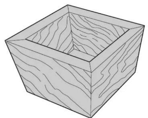
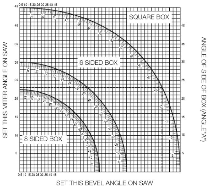
Compound mitre (fig. O1 & O2)
A compound mitre is a cut made using a mitre angle (fig. N2) and a bevel angle (fig. N1) at the same time. This is the type of cut used to make frames or boxes with slanting sides like the one shown in fig. O1.

If the cutting angle varies from cut to cut, check that the bevel clamp knob and the mitre lock knob are securely tightened. These knobs must be tightened after making any changes in bevel or mitre.
- The chart shown below will assist you in selecting the proper bevel and mitre settings for common compound mitre cuts. To use the chart, select the desired angle "A" (fig. O2) of your project and locate that angle on the appropriate arc in the chart. From that point follow the chart straight down to find the correct bevel angle and straight across to find the correct mitre angle.
- Set your saw to the prescribed angles and make a few trial cuts.
• Practice fitting the cut pieces together.
- Example: To make a 4 sided box with 25^ exterior angles (angle "A") (fig. O2), use the upper right arc. Find 25^ on the arc scale. Follow the horizontal intersecting line to either side to get the mitre angle setting on the saw (23^) . Likewise follow the vertical intersecting line to the top or bottom to get the bevel angle setting on the saw (40^) . Always try cuts on a few scrap pieces of wood to verify the settings on the saw.
line
| SET THIS BEVEL ANGLE ON SAW | SET THIS MITER ANGLE ON SAW | ANGLE OF SIDE OF BOX (ANGLE''A'') | | --------------------------- | --------------------------- | --------------------------------- | | 0.5 | 45 | 10 | | 1.0 | 44 | 15 | | 1.5 | 43 | 20 | | 2.0 | 42 | 25 | | 2.5 | 41 | 30 | | 3.0 | 40 | 35 | | 3.5 | 39 | 40 | | 4.0 | 38 | 45 | | 4.5 | 37 | 50 | | 5.0 | 36 | 55 | | 5.5 | 35 | 60 | | 6.0 | 34 | 65 | | 6.5 | 33 | 70 | | 7.0 | 32 | 75 | | 7.5 | 31 | 80 | | 8.0 | 30 | 85 | | 8.5 | 29 | 90 | | 9.0 | 28 | 95 | | 9.5 | 27 | 100 | | 10.0 | 26 | 105 | | 10.5 | 25 | 110 | | 11.0 | 24 | 115 | | 11.5 | 23 | 120 | | 12.0 | 22 | 125 | | 12.5 | 21 | 130 | | 13.0 | 20 | 135 | | 13.5 | 19 | 140 | | 14.0 | 18 | 145 | | 14.5 | 17 | 150 | | 15.0 | 16 | 155 | | 15.5 | 15 | 160 | | 16.0 | 14 | 165 | | 16.5 | 13 | 170 | | 17.0 | 12 | 175 | | 17.5 | 11 | 180 | | 18.0 | 10 | 185 | | 18.5 | 9 | 190 | | 19.0 | 8 | 195 | | 19.5 | 7 | 200 | | 20.0 | 6 | 205 | | 20.5 | 5 | 210 | | 21.0 | 4 | 215 | | 21.5 | 3 | 220 | | 22.0 | 2 | 225 | | 22.5 | 1 | 230 | | 23.0 | 0 | 235 | | 23.5 | -1 | 240 | | 24.0 | -2 | 245 | | 24.5 | -3 | 250 | | 25.0 | -4 | 255 | | 25.5 | -5 | 260 | | 26.0 | -6 | 265 | | 26.5 | -7 | 270 | | 27.0 | -8 | 275 | | 27.5 | -9 | 280 | | 28.0 | -10 | 285 | | 28.5 | -11 | 290 | | 29.0 | -12 | 295 | | 29.5 | -13 | 300 | | 30.0 | -14 | 305 | | 30.5 | -15 | 310 | | 31.0 | -16 | 315 | | 31.5 | -17 | 320 | | 32.0 | -18 | 325 | | 32.5 | -19 | 330 | | 33.0 | -20 | 335 | | 33.5 | -21 | 340 | | 34.0 | -22 | 345 | | 34.5 | -23 | 350 | | 35.0 | -24 | 355 | | 35.5 | -25 | 360 | | 36.0 | -26 | 365 | | 36.5 | -27 | 370 | | 37.0 | -28 | 375 | | 37.5 | -29 | 380 | | 38.0 | -30 | 385 | | 38.5 | -31 | 390 | | 39.0 | -32 | 395 | | 39.5 | -33 | 400 | | 40.0 | -34 | nan | The data is presented in a table format with three columns: Label (X) and Label (Y). The labels for the boxes are 'Square Box', '6 SIDED BOX', and '8 SIDED BOX'. The values for the boxes are annotated above the boxes.Vernier scale (fig. P1 - P3)
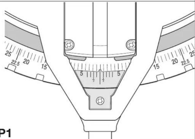
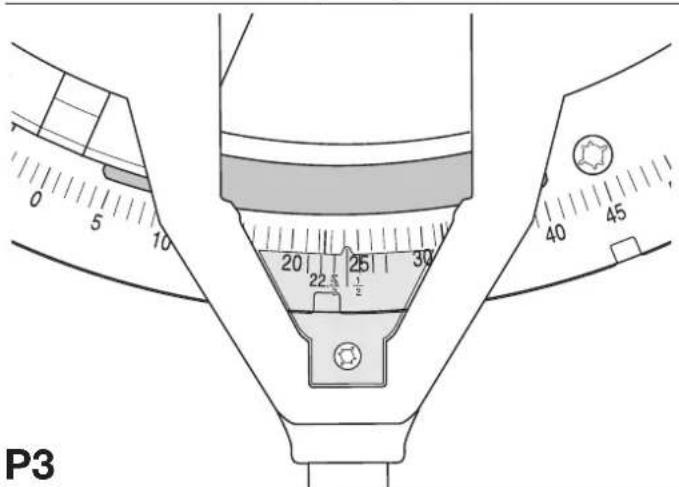
Your saw is equipped with a vernier scale for added precision. For settings that require partial degrees (14^, 12^, 34^) , the vernier scale allows you to accurately set mitre angles to the nearest 14^ (15 minutes). To use the vernier scale follow the steps listed below.
As an example, assume that the angle you want to mitre is 24^1/4 right.
- Switch off the mitre saw.
- Set the mitre angle to the nearest whole degree desired by aligning the centre mark in the vernier scale, shown in fig. P1, with the whole degree number etched in the mitre scale. Examine fig. P2 closely; the setting shown is 24^ right mitre.
- To set the additional 1/4^ , squeeze the mitre arm lock and carefully move the arm to the right until the 1/4^ vernier mark aligns with the closest degree mark on the mitre scale. In this example, the closest degree mark on the mitre scale happens to be 25^ . Fig. P3 shows a setting of 24^1/4^ right mitre.
- When mitring to the right: - increase the mitre angle by moving the arm to align the appropriate vernier mark with the closest mark on the mitre scale to the right. - decrease the mitre angle by moving the arm to align the appropriate vernier mark with the closest mark on the mitre scale to the left.
- When mitring to the left: - increase the mitre angle by moving the arm to align the appropriate vernier mark with the closest mark on the mitre scale to the left. - decrease the mitre angle by moving the arm to align the appropriate vernier mark with the closest mark on the mitre scale to the right.
Cutting base mouldings
The cutting of base moulding is performed at a 45^ bevel angle.
• Always make a dry run without power before making any cuts.
- All cuts are made with the back of the moulding laying flat on the saw.
Inside corner
- Left side
- Position the moulding with top of the moulding against the fence.
- Save the left side of the cut.
- Right side
- Position the moulding with the bottom of the moulding against the fence.
- Save the left side of the cut.
Outside corner
Left side
- Position the moulding with the bottom of the moulding against the fence.
- Save the right side of the cut.
- Right side
- Position the moulding with top of the moulding against the fence.
- Save the right side of the cut.
Cutting crown mouldings
The cutting of crown moulding is performed in a compound mitre. In order to achieve extreme accuracy, your saw has pre-set angle positions at 31.62^ mitre and 33.85^ bevel. These settings are for standard crown mouldings with 52^ angles at the top and 38^ angles at the bottom.
- Make test cuts using scrap material before doing the final cuts.
- All cuts are made in a left bevel and with the back of the moulding against the base.
Inside corner
- Left side
- Top of the moulding against the fence.
- Mitre right.
- Save the left side of the cut.
- Right side
- Bottom of the moulding against the fence.
- Mitre left.
- Save the left side of the cut.
Outside corner
- Left side
- Bottom of the moulding against the fence.
- Mitre left.
- Save the left side of the cut.
- Right side
- Top of the moulding against the fence.
- Mitre right.
- Save the right side of the cut.

Dust extraction (fig. A2 & A6)
- Fit the dustbag (32) onto the dust spout (20).
- Whenever possible, connect a dust extraction device designed in accordance with the relevant regulations regarding dust emission.
Saw blades
To obtain the stated cutting capacities, always use 250 mm saw blades with 30 mm arbor holes.
Consult your dealer for further information on the appropriate accessories.
Transporting (fig. B)
In order to conveniently carry the mitre saw, a carrying handle (9) has been included on the top of the saw arm.
- To transport the saw, lower the arm and depress the lock down pin (18).
- Always use the carrying handle (9) or the hand indentations (22) shown in fig. B to transport the saw.
Maintenance
Your DeWALT Power Tool has been designed to operate over a long period of time with a minimum of maintenance. Continuous satisfactory operation depends upon proper tool care and regular cleaning.

Cleaning
Keep the ventilation slots clear and regularly clean the housing with a soft cloth.
- Regularly clean the table top.
- Regularly clean the dust collection system.

Unwanted tools and the environment
Take your tool to an authorized DeWALT repair agent where it will be disposed of in an environmentally safe way.
GUARANTEE
• 30 DAY NO RISK SATISFACTION GUARANTEE •
If you are not completely satisfied with the performance of your DEWALT machine, simply return it within 30 days, complete as purchased, to the point of purchase, for a full refund or exchange. Proof of purchase must be produced.
- ONE YEAR FREE SERVICE CONTRACT •
If you need maintenance or service for your D≡WALT machine, in the 12 months following purchase, it will be undertaken free of charge at an authorized D≡WALT repair agent. Proof of purchase must be produced. Includes labour and spare parts for Power Tools. Excludes accessories.
• ONE YEAR WARRANTY •
If your DeWALT product becomes defective due to faulty materials or workmanship within 12 months from the date of purchase, we guarantee to replace all defective parts free of charge or, at our discretion, replace the unit free of charge provided that:
• The product has not been misused.
• Repairs have not been attempted by unauthorized persons.
• Proof of purchase date is produced.
This guarantee is offered as an extra benefit and is additional to consumers statutory rights.
For the location of your nearest authorized DeWALT repair agent, please use the appropriate telephone number on the back of this manual. Alternatively, a list of authorized DeWALT repair agents and full details on our after-sales service are available on the Internet at www.2helpU.com.
INGLETADORA DW702/DW703
¡Enhorabuena!
Director Engineering and Product Development Horst Großmann

text_image
X. fopsmannProduct and Safety GmbH (TRPS)
Am Grauen Stein 1
D-51105 Köln
Germany
Cert. No.
AM2110437.01
Product and Safety GmbH (TRPS)
Am Grauen Stein 1
D-51105 Köln
Germany
Cert. No.
AM2110437.01
(Isolation double) - outils
L'emballage contient:
text_image
Scanned text of a document with dense, illegible handwritten or typed charactersProduct and Safety GmbH (TRPS)
Am Grauen Stein 1
D-51105 Köln
Germany
Cert. No.
AM2110437.01
Director Engineering and Product Development Horst Großmann

text_image
X. JopsmannDeWALT, Richard-Klinger-Straße 40, D-65510, Idstein, Duitsland
TÜV Rheinland
Product and Safety GmbH (TRPS)
Am Grauen Stein 1
D-51105 Köln
Germany
Cert. No.
AM2110437.01
Director Engineering and Product Development Horst Großmann

text_image
X. fopsmannDeWALT, Richard-Klinger-Straße 40, D-65510, Idstein, Tyskland
TÜV Rheinland
Product and Safety GmbH (TRPS)
Am Grauen Stein 1
D-51105 Köln
Germany
Sert. Nr.
AM2110437.01
Director Engineering and Product Development
Horst Großmann

text_image
X. fopsmannProduct and Safety GmbH (TRPS)
Am Grauen Stein 1
D-51105 Köln
Germany
Cert. No.
AM2110437.01
11 Retire as chaves de ajuste
1 Lâmina, TCG (DW702)
2 Grampos (DW702)
Director Engineering and Product Development Horst Großmann

text_image
X. JopsmannProduct and Safety GmbH (TRPS)
Am Grauen Stein 1
D-51105 Köln
Germany
Cert. No.
AM2110437.01
Turvaohjeet
Director Engineering and Product Development Horst Großmann

text_image
X. fopsmannDeWALT, Richard-Klinger-Straße 40, D-65510, Idstein, Tyskland
TÜV Rheinland
Product and Safety GmbH (TRPS)
Am Grauen Stein 1
D-51105 Köln
Germany
Cert. No.
AM2110437.01
GÖNYE TESTERESİ DW702/DW703
Tebrikler!
Product and Safety GmbH (TRPS)
Am Grauen Stein 1
D-51105 Köln
Almanya
Vesika numarası
AM2110437.01
Product and Safety GmbH (TRPS)
Am Grauen Stein 1
D-51105 Köln
Germany
| Cert. No. | |
| AM2110437.01 |
Οδηγίες ασφαλείας
| DeWALT Tel: 00353-2781800Calpe House Rock HillBlack Rock, Co. Dublin |
Italia
| DEWALT Tel: 0800-014353Viale Elvezia 220052 Monza (Mi) |
Nederland