
DW713XPS - Saw DEWALT - Free user manual and instructions
Find the device manual for free DW713XPS DEWALT in PDF.

| Brand | DeWalt |
| Model | DW713XPS |
| Product Type | Miter Saw |
| Voltage | 230 V |
| Motor Power | 1600 W |
| Blade Diameter | 250 mm |
| Max Blade Speed | 5000 min⁻¹ |
| Max Crosscut Capacity at 90° | 162 mm |
| Max Miter Capacity at 45° | 114 mm |
| Max Depth of Cut at 90° | 90 mm |
| Max Depth of Cut at Bevel 45° | 58 mm |
| Miter Range | 50° left / 50° right |
| Bevel Range | 48° left / 48° right |
| Weight | 15 kg |
| Electric Automatic Brake | < 10 s |
| LED Light (DW713XPS) | Yes |
| Sound Pressure Level | 91 dB(A) |
| Sound Power Level | 102 dB(A) |
| Vibration Emission Value | 2.6 m/s² |
| Double Insulation | Yes (Class II) |
| Warranty | 1 year full + 30 days satisfaction |
Frequently Asked Questions - DW713XPS DEWALT
User questions about DW713XPS DEWALT
0 question about this device. Answer the ones you know or ask your own.
Ask a new question about this device
Download the instructions for your Saw in PDF format for free! Find your manual DW713XPS - DEWALT and take your electronic device back in hand. On this page are published all the documents necessary for the use of your device. DW713XPS by DEWALT.
USER MANUAL DW713XPS DEWALT
English (original instructions)
Figure 5
natural_image
Technical line drawing of a mechanical assembly with no visible text or symbolsFigure 6
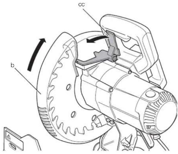
Figure 7
natural_image
Technical line drawing of a mechanical assembly with no visible text or symbolsFigure 8
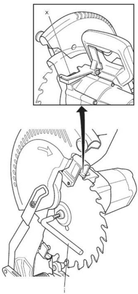
Figure 9
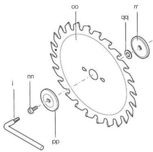
Figure 10
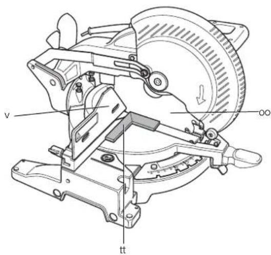
Figure 11
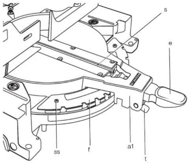
Figure 12
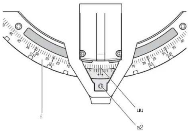
Figure 13
natural_image
Technical diagram of a mechanical component with no visible text or symbolsFigure 14
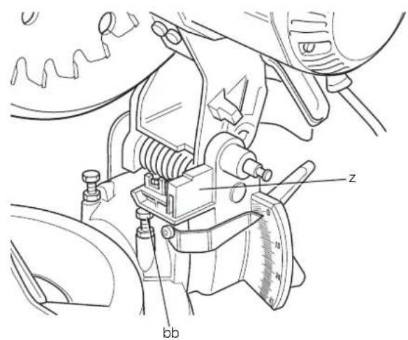
Figure 15
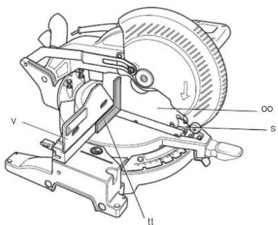
Figure 16
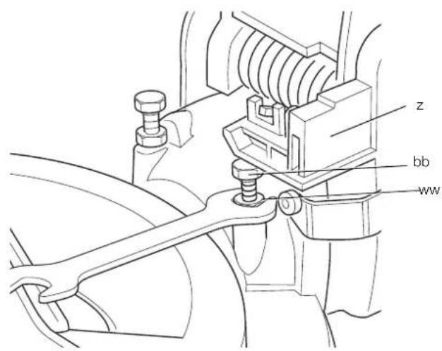
Figure 17
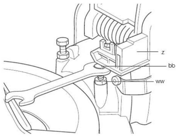
Figure 18
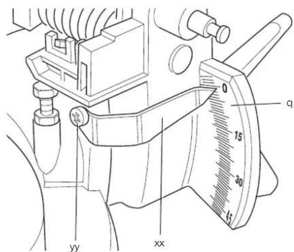
Figure 19
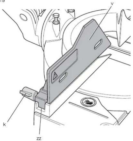
Figure 20
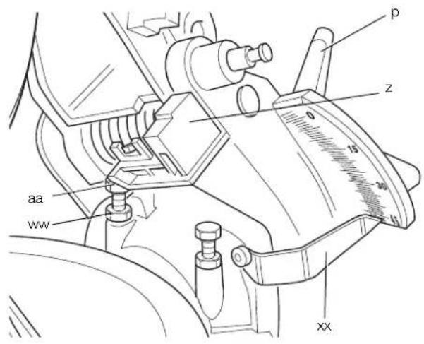
Figure 21
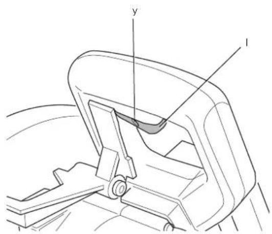
Figure 22
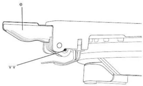
Figure 23
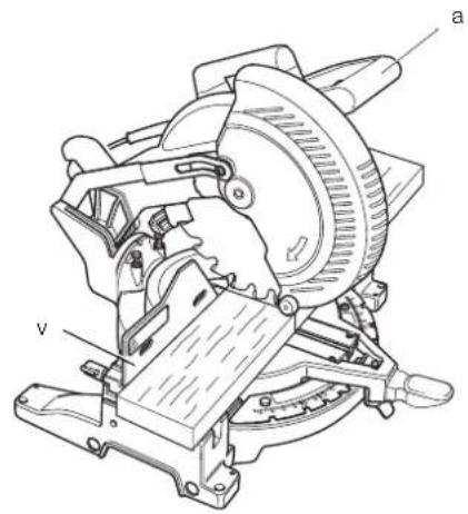
Figure 24
natural_image
Technical line drawing of a mechanical cutting or milling machine (no text or symbols)Figure 25
natural_image
Technical line drawing of a mechanical assembly with no visible text or symbolsFigure 26
natural_image
Illustration of a wooden plank with visible grain patterns and texture (no text or symbols)Figure 27
natural_image
3D illustration of a V-shaped wooden plank with visible grain patterns (no text or symbols)Figure 28
natural_image
Isometric line drawing of a wooden box with visible grain patterns (no text or symbols)Figure 29
natural_image
Diagram of a rectangular container with wavy internal lines and an arrow labeled 'A' indicating direction (no text or symbols beyond label)Figure 30
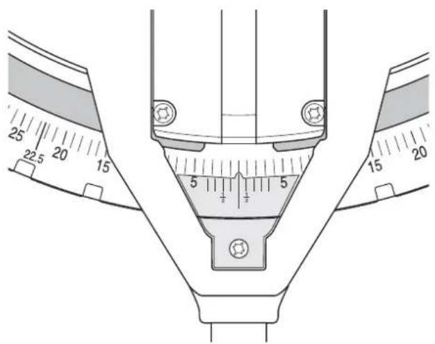
Figure 31
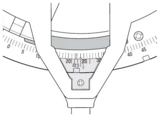
Figure 32
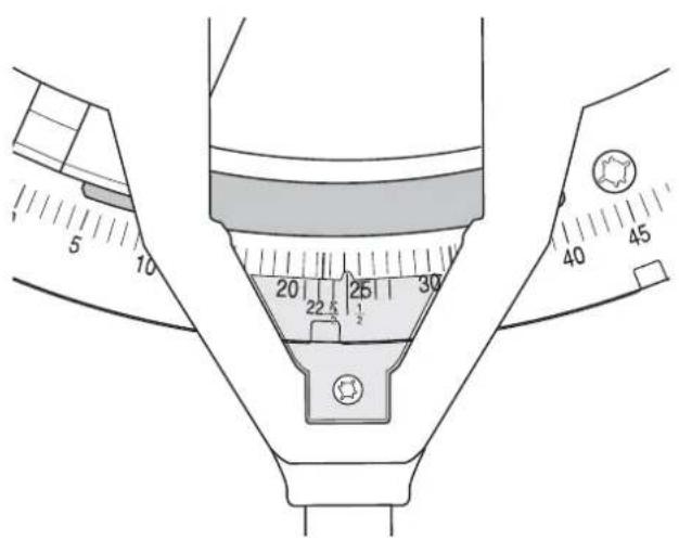
Figure 34
natural_image
Technical line drawing of a mechanical assembly with wooden components and mounting brackets (no text or symbols)Figure 35
natural_image
Prohibition sign with a circular border and diagonal line crossing over a mechanical component (no text or symbols)Figure 37
natural_image
Line drawing of a hand using a lathe tool to cut a mechanical component, no text or symbols presentGERINGSSAV DW713, DW713XPS
Tillykke!
KLASSE 2 LED-PRODUKT
MAKSIMAL UDGANGSSTRÖM
P = 9,2mW;
_peak = 456nm
IEC 60825-1:1:1993; +A1:1997; +A2:2001
D-65510, Idstein, Germany
29.12.2009
Sicherheitshinweise

_peak = 456 nm
IEC 60825-1:1:1993; +A1:1997; +A2:2001
You have chosen a DEWALT tool. Years of experience, thorough product development and innovation make DEWALT one of the most reliable partners for professional power tool users.
Technical Data
| DW713/DW713XPS | |||
| Voltage | V | 230 | |
| (U.K. & Ireland only) V 230/115 | |||
| Type 2 | |||
| Power input W 1600 | |||
| Blade diameter | mm | 250 | |
| Max. blade speed min | -1 | 5000 | |
| Max. cross-cut capacity 90° | mm | 162 | |
| Max. mitre capacity 45° | mm | 114 | |
| Max. depth of cut 90° | mm | 90 | |
| Max. depth of bevel cross-cut 45° | mm | 58 | |
| Mitre (max. positions) | left | 50° | |
| right | 50° | ||
| Bevel (max. positions) | left | 48° | |
| right | 48° | ||
| 0° mitre | |||
| Resulting width at max. height 90 mm | mm | 95 | |
| Resulting height at max. width 90 mm | mm | 41 | |
| 45° mitre | |||
| Resulting width at max. height 90 mm | mm | 67 | |
| Resulting height at max. width 90 mm | mm | 41 | |
| 45° bevel | |||
| Resulting width at max. height 61 mm | mm | 95 | |
| Resulting height at max. width 161 mm | mm | 25 | |
| 31.62° mitre, 33.85° bevel | |||
| Resulting height at max. width 133 mm | mm | 20 | |
| Automatic blade brake time | s | < 10.0 | |
| Weight | kg | 15° | |
* DW713XPS with Worklight LED
| L_FA | (sound pressure) | dB(A) 91.0 | ||
| K_FA | (sound pressure uncertainty) | dB(A) | 3.0 | |
| L_FAA | (sound power) | dB(A) | 102.0 | |
| K_FAA | (sound power uncertainty) | dB(A) | 3.0 |
Vibration total values (triax vector sum)
determined according to EN 61029-1, EN 61029-2-9:
Vibration emission value a_h
| a_n = | m/s2 | 2.6 |
| Uncertainty K = | m/s2 | 1.5 |
The vibration emission level given in this information sheet has been measured in accordance with a standardised test given in EN 61029 and may be used to compare one tool with another. It may be used for a preliminary assessment of exposure.

WARNING: The declared vibration emission level represents the main applications of the tool. However if the tool is used for different applications, with different accessories or poorly maintained, the vibration emission may differ. This may significantly increase the exposure level over the total working period.
An estimation of the level of exposure to vibration should also take into account the times when the tool is switched off or when it is running but not actually doing the job. This may significantly reduce the exposure level over the total working period.
Identify additional safety measures to protect the operator from the effects of vibration such as: maintain the tool and the accessories, keep the hands warm, organisation of work patterns.
Fuses
| Europe | 230 V tools | 10 Amperes, mains |
| U.K. & Ireland | 230 V tools | 13 Amperes, in plugs |
| U.K. & Ireland | 115 V tools | 16 Amperes, mains |
NOTE: This device is intended for the connection to a power supply system with maximum permissible system impedance Zmax of 0.30 Ω at the interface point (power service box) of user's supply.
The user has to ensure that this device is connected only to a power system which fulfils the requirement above. If necessary, the user can ask the public power supply company for the system impedance at the interface point.
Definitions: Safety Guidelines
The definitions below describe the level of severity for each signal word. Please read the manual and pay attention to these symbols.

DANGER: Indicates an imminently hazardous situation which, if not avoided, will result in death or serious injury.
WARNING: Indicates a potentially hazardous situation which, if not avoided, could result in death or serious injury.

CAUTION: Indicates a potentially hazardous situation which, if not avoided, may result in minor or moderate injury.
NOTICE: Indicates a practice not related to personal injury which, if not avoided, may result in property damage.

Denotes risk of electric shock.

Denotes risk of fire.
EC-Declaration of Conformity
MACHINERY DIRECTIVE

DW713/DW713XPS
DEWALT declares that these products described under "technical data" are in compliance with: 2006/42/EC, EN 61029-1, EN 61029-2-9.
These products also comply with Directive 2004/108/EC. For more information, please contact DEWALT at the following address or refer to the back of the manual.
The undersigned is responsible for compilation of the technical file and makes this declaration on behalf of DEWALT.

Horst Grossmann
Vice President Engineering and Product Development
D-65510, Idstein, Germany
29.12.2009
Safety Instructions

WARNING! When using electric tools basic safety precautions should always be followed to reduce the risk of fire, electric shock and personal injury including the following.
Read all these instructions before attempting to operate this product and save these instructions.
SAVE THIS MANUAL FOR FUTURE REFERENCE
General Safety Rules
1. Keep work area clear.
Cluttered areas and benches invite injuries.
2. Consider work area environment.
Do not expose the tool to rain. Do not use the tool in damp or wet conditions. Keep the work area well lit (250–300 Lux). Do not use the tool where there is a risk of causing fire or explosion, e.g., in the presence of flammable liquids and gases.
3. Guard against electric shock.
Avoid body contact with earthed surfaces (e.g., pipes, radiators, cookers and refrigerators). When using the tool under extreme conditions (e.g., high humidity, when metal swarf is being produced, etc.), electric safety can be improved by inserting an isolating transformer or a (FI) earth-leakage circuit-breaker.
4. Keep other persons away.
Do not let persons, especially children, not involved in the work, touch the tool or the extension cord and keep them away from the work area.
5. Store idle tools.
When not in use, tools must be stored in a dry place and locked up securely, out of reach of children.
6. Do not force the tool.
It will do the job better and safer at the rate to which it was intended.
7. Use the right tool.
Do not force small tools to do the job of a heavy duty tool. Do not use tools for purposes not intended; for example do not use circular saws to cut tree limbs or logs.
8. Dress properly.
Do not wear loose clothing or jewellery, as these can be caught in moving parts. Non-skid footwear is recommended when working outdoors. Wear protective hair covering to contain long hair.
9. Use protective equipment.
Always use safety glasses. Use a face or dust mask if working operations create dust or flying particles. If these particles might be considerably hot, also wear a heat-resistant apron. Wear ear protection at all times. Wear a safety helmet at all times.
10. Connect dust extraction equipment.
If devices are provided for the connection of dust extraction and collecting equipment, ensure these are connected and properly used.
11. Do not abuse the cord.
Never yank the cord to disconnect it from the socket. Keep the cord away from heat, oil and sharp edges. Never carry the tool by its cord.
12. Secure work.
Where possible use clamps or a vice to hold the work. It is safer than using your hand and it frees both hands to operate the tool.
13. Do not overreach.
Keep proper footing and balance at all times.
14. Maintain tools with care.
Keep cutting tools sharp and clean for better and safer performance. Follow instructions for lubricating and changing accessories. Inspect tools periodically and if damaged have them repaired by an authorized service facility. Keep handles and switches dry, clean and free from oil and grease.
15. Disconnect tools.
When not in use, before servicing and when changing accessories such as blades, bits and cutters, disconnect tools from the power supply.
16. Remove adjusting keys and wrenches.
Form the habit of checking to see that adjusting keys and wrenches are removed from the tool before operating the tool.
17. Avoid unintentional starting.
Do not carry the tool with a finger on the switch. Be sure that the tool is in the "off" position before plugging in.
18. Use outdoor extension leads.
Before use, inspect the extension cable and replace if damaged. When the tool is used outdoors, use only extension cords intended for outdoor use and marked accordingly.
19. Stay alert.
Watch what you are doing. Use common sense. Do not operate the tool when you are tired or under the influence of drugs or alcohol.
20. Check for damaged parts.
Before use, carefully check the tool and mains cable to determine that it will operate properly and perform its intended function. Check for alignment of moving parts, binding of moving parts, breakage of parts, mounting and any other conditions that may affect its operation. A guard or other part that is damaged should be properly repaired or replaced by an authorized service centre unless otherwise indicated in this instruction manual. Have defective switches replaced by an authorized service centre. Do not use the tool if the switch does not turn it on and off. Never attempt any repairs yourself.

WARNING! The use of any accessory or attachment or performance of any operation with this tool other than those recommended in this instruction manual may present a risk of personal injury.
21. Have your tool repaired by a qualified person.
This electric tool complies relevant safety rules. Repairs should only be carried out by qualified persons using original spare parts; otherwise this may result in considerable danger to the user.
Additional Safety Rules for Mitre Saws
- The machine is provided with a special configured power supply cord which can only be replaced by the manufacturer or its authorised service agent.
- Do not use the saw to cut other materials than those recommended by the manufacturer.
- Do not operate the machine without guards in position, or if guards do not function or are not maintained properly.
- Ensure that the arm is securely fixed when performing bevel cuts.
- Keep the floor area around the machine level, well-maintained and free of loose materials, e.g., chips and cut-offs.
- Use correctly sharpened saw blades. Observe the maximum speed mark on the saw blade.
- Make sure all locking knobs and clamp handles are tight before starting any operation.
- Never place either hand in the blade area when the saw is connected to the electrical power source.
- Never attempt to stop a machine in motion rapidly by jamming a tool or other means against the blade; serious accidents can occur.
- Before using any accessory consult the instruction manual. The improper use of an accessory can cause damage.
- Use a holder or wear gloves when handling a saw blade.
- Ensure that the saw blade is mounted correctly before use.
- Make sure that the blade rotates in the correct direction.
- Do not use blades of larger or smaller diameter than recommended. For the proper blade rating refer to the technical data. Use only the blades specified in this manual, complying with EN 847-1.
- Consider applying specially designed noise-reduction blades.
- Do not use HSS blades.
- Do not use cracked or damaged saw blades.
- Do not use any abrasive or diamond discs.
- Never use your saw without the kerf plate.
- Raise the blade from the kerf in the workpiece prior to releasing the switch.
-
Do not wedge anything against the fan to hold the motor shaft.
-
The blade guard on your saw will automatically raise when the arm is brought down; it will lower over the blade when head lock up release lever (cc) is pushed.
- Never raise the blade guard manually unless the saw is switched off. The guard can be raised by hand when installing or removing saw blades or for inspection of the saw.
- Check periodically that the motor air slots are clean and free of chips.
- Replace the kerf plate when worn. Refer to service parts list included.
- Disconnect the machine from the mains before carrying out any maintenance work or when changing the blade.
- Never perform any cleaning or maintenance work when the machine is still running and the head is not in the rest position.
- When possible, always mount the machine to a bench.
- If you use an LED to indicate the cutting line, make sure that the LED is of class 2 according to EN 60825-1. Do not replace an LED diode with a different type. If damaged, have the LED repaired by an authorised repair agent.
- The front section of the guard is louvered for visibility while cutting. Although the louvers dramatically reduce flying debris, they are openings in the guard and safety glasses should be worn at all times when viewing through the louvers.
- Connect the saw to a dust collection device when sawing wood. Always consider factors which influence exposure of dust such as:
-- type of material to be machined (chip board produces more dust than wood);
-- sharpness of the saw blade;
-- correct adjustment of the saw blade,
-- dust extractor with air velocity not less than 20 m/s.
Ensure that the local extraction as well as hoods, baffles and chutes are properly adjusted.
- Please be aware of the following factors influencing exposure to noise:
-- use saw blades designed to reduce the emitted noise;
-- use only well sharpened saw blades;
• Machine maintenance shall be conducted periodically;
- Machine faults, including guards or saw blade, shall be reported as soon as they are discovered;
- Provide adequate general or localized lighting;
- Ensure the operator is adequately trained in the use, adjustment and operation of the machine;
- Ensure that any spacers and spindle rings are suitable for the purpose as stated in this manual.
- Refrain from removing any cut-offs or other parts of the workpiece from the cutting area while the machine is running and the saw head is not in the rest position
- Never cut workpieces shorter than 30 mm.
- Without additional support the machine is designed to accept the maximum workpiece size of:
– Height 90 mm by width 90 mm by length 500 mm
- Longer workpieces need to be supported by suitable additional table, e.g. DE7080. Always clamp the workpiece safely.
- In case of an accident or machine failure, immediately turn the machine off and disconnect machine from the power source.
- Report the failure and mark the machine in suitable form to prevent other people from using the defective machine.
- When the saw blade is blocked due to abnormal feed force during cutting, turn the machine off and disconnect it from power supply. Remove the workpiece and ensure that the saw blade runs free. Turn the machine on and start new cutting operation with reduced feed force.
- Never cut light alloy, especially magnesium.
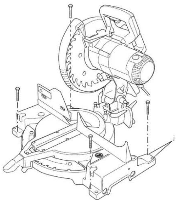
- Whenever the situation allows, mount the machine to a bench using bolts with a diameter of 8 mm and 80 mm in length (fig.j).
Residual Risks
The following risks are inherent to the use of saws:
– injuries caused by touching the rotating parts
In spite of the application of the relevant safety regulations and the implementation of safety devices, certain residual risks cannot be avoided. These are:
- Impairment of hearing.
- Risk of accidents caused by the uncovered parts of the rotating saw blade.
– Risk of injury when changing the blade.
– Risk of squeezing fingers when opening the guards.
– Health hazards caused by breathing dust developed when sawing wood, especially oak, beech and MDF.
The following factors increase the risk of breathing problems:
- No dust extractor connected when sawing wood.
- Insufficient dust extraction caused by uncleaned exhaust filters.
Markings on Tool
The following pictograms are shown on the tool:

Read instruction manual before use.

Wear ear protection.

Wear eye protection.

Carrying point

Keep hands away from blade.
DATE CODE POSITION (FIG. 1)
The Date Code (u), which also includes the year of manufacture, is printed into the housing.
Example:
2010 XX XX
Year of Manufacture
Package Contents
The package contains:
1 Mitre Saw
1 Blade wrench stored in wrench pocket
1 Saw blade
1 Dust bag
1 LED Worklight System (DW713XPS)
1 Instruction manual
1 Exploded drawing
- Check for damage to the tool, parts or accessories which may have occurred during transport.
- Take the time to thoroughly read and understand this manual prior to operation.
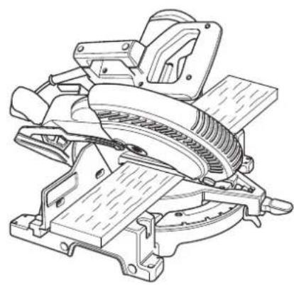
Description (fig. 1, 2)

WARNING: Never modify the power tool or any part of it. Damage or personal injury could result.
a. Operating handle
b. Lower guard
c. Right side, fence
d. Table
e. Mitre lock lever
f. Mitre scale
g. Base
h. Holes for extension kit
i. Wrench
j. Bench mounting holes
k. Fence clamping knob
I. On/Off switch
m. Carrying handle
n. Dust spout
o. Lock down pin
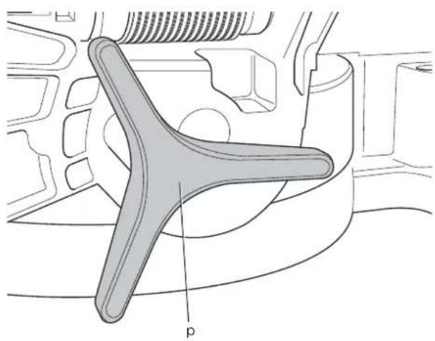
p. Bevel clamp knob
q. Bevel scale
r. Hand indentation
s. Kerf plate
t. Mitre detent
u. Date code
v. left side, fence
w. Motor housing
x. Spindle lock
y. Hole for padlock
z. Angle position stop
aa. Bevel position adjustment stop
bb. Vertical position adjustment stop
cc. Head lock up lever
dd. Rear lower guard
ee. Upper guard
Optional Accessories (fi g. 3)
ff. Dust bag
gg. Clamp
hh. LED Worklight System
ii. Length stop
jj. Work support
INTENDED USE
Your DEWALT DW713 Mitre Saw has been designed for professional cutting wood, wood products and plastics. It performs the sawing operations of cross-cutting, bevelling and mitring easily, accurately and safely.
This unit is designed for use with a nominal blade diameter 216 mm carbide tip blade.
DO NOT use under wet conditions or in presence of flammable liquids or gases.
These miter saws are professional power tools.
DO NOT let children come into contact with the tool. Supervision is required when inexperienced operators use this tool.

WARNING! Do not use the machine for purposes other than intended.
Electrical Safety
The electric motor has been designed for one voltage only. Always check that the power supply corresponds to the voltage on the rating plate.

Your tool is double insulated in accordance with EN 61029; therefore no earth wire is required.

WARNING: 115 V units have to be operated via a fail-safe isolating transformer with an earth screen between the primary and secondary winding.
In case of cord replacement the tool must only be repaired by an authorized service agent or by qualified electrician.
Mains Plug Replacement (U.K. & Ireland only)
If a new mains plug needs to be fitted:
- Safely dispose of the old plug.
- Connect the brown lead to the live terminal in the plug.
- Connect the blue lead to the neutral terminal.

WARNING: No connection is to be made to the earth terminal.
Follow the fitting instructions supplied with good quality plugs. Recommended fuse: 13 A.
Fitting a Mains Plug to 115 V Units (U.K. and Ireland Only)
- The plug fitted should be comply with BS EN 60309 (BS4343), 16 Amps, earthing contact position 4h.

WARNING: Always ensure that the cable clamp is correctly and securely fitted to the sheath of the cable.
Using an Extension Cable
If an extension cable is required, use an approved 3-core extension cable suitable for the power input of this tool (see technical data).
The minimum conductor size is 1.5 mm ^2 . When using a cable reel, always unwind the cable completely.
ASSEMBLY

WARNING: To reduce the risk of injury, turn unit off and disconnect machine from power source before installing and removing accessories, before adjusting or changing set-ups or when making repairs. Be sure the trigger switch is in the OFF position. An accidental start-up can cause injury.
Unpacking (fig. 1, 2, 4)
- Remove the saw from the packing material carefully using the carrying handle (m).
- Press down the operating handle (a) and pull out the lock down pin (o), as shown.
- Gently release the downward pressure and allow the arm to rise to its full height.
Bench Mounting (fig. 5)
-
Holes (j) are provided in all four feet to facilitate bench mounting. Two different sized holes are provided to accommodate different sizes of bolts. Use either hole; it is not necessary to use both. Bolts with a diameter of 8 mm and 80 mm in length is suggested. Always mount your saw firmly to prevent movement. To enhance the portability, the tool can be mounted to a piece of 12.5 mm or thicker plywood which can then be clamped to your work support or moved to other job sites and reclamped.
-
When mounting your saw to a piece of plywood, make sure that the mounting screws do not protrude from the bottom of the wood. The plywood must sit flush on the work support. When clamping the saw to any work surface, clamp only on the clamping bosses where the mounting screw holes are located. Clamping at any other point will interfere with the proper operation of the saw.
-
To prevent binding and inaccuracy, be sure the mounting surface is not warped or otherwise uneven. If the saw rocks on the surface, place a thin piece of material under one saw foot until the saw is firm on the mounting surface.
Mounting the Saw Blade (fi g. 6, 7, 8, 9)

WARNING: To reduce the risk of injury, turn unit off and disconnect machine from power source before installing and removing accessories, before adjusting or changing set-ups or when making repairs. Be sure the trigger switch is in the OFF position. An accidental start-up can cause injury.
- Never depress the spindle lock button while the blade is under power or coasting.
ENGLISH
- Do not cut light alloy and ferrous metal (containing iron or steel) or masonry or fibre cement product with this mitre saw.
-
Depress the head lock up release lever (cc) to release the lower guard (b), then raise the lower guard as far as possible.
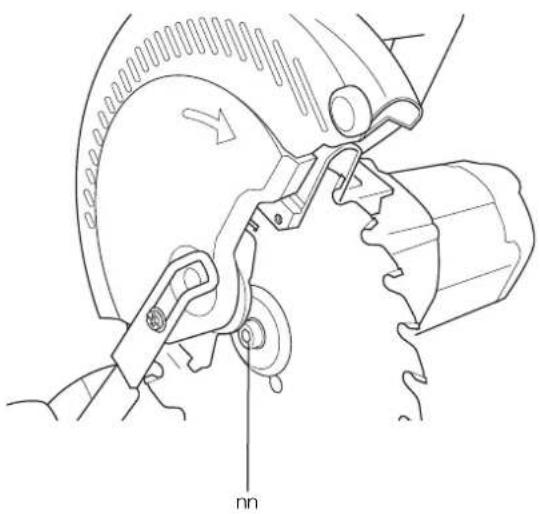
-
With the lower guard held in the raised position, depress the spindle lock button (x) with one hand, then use the supplied blade spanner (i) in the other hand to loosen the left-hand threaded blade locking screw (nn) by turning clockwise.

WARNING! To use the spindle lock, press the button as shown and rotate the spindle by hand until you feel the lock engage.
Continue to hold the lock button in to keep the spindle from turning.
-
Remove the blade locking screw (nn) and the outside arbor collar (pp).
-
Install the saw blade (oo) onto the blade adaptor (qq) seated directly against the inside arbor collar (rr), making sure that the teeth at the bottom edge of the blade are pointing toward the back of the saw (away from the operator).
-
Replace the outer arbor collar (pp).
-
Tighten the blade locking screw (nn) carefully by turning counterclockwise while holding the spindle lock engaged with your other hand.

WARNING! Be aware the saw blade shall be replaced in the described way only. Only use saw blades as specified under Technical Data; Cat.no.: DT4323 is suggested.
Adjustments

WARNING: To reduce the risk of injury, turn unit off and disconnect machine from power source before installing and removing accessories, before adjusting or changing set-ups or when making repairs. Be sure the trigger switch is in the OFF position. An accidental start-up can cause injury.
Your mitre saw was accurately adjusted at the factory. If readjustment due to shipping and handling or any other reason is required, follow the steps below to adjust your saw. Once made, these adjustments should remain accurate.
CHECKING AND ADJUSTING THE MITRE SCALE (FIG. 10, 11)
- Release the mitre lock lever (e) and swing the mitre arm until the latch locates it at the 0^ mitre position. Do not lock miter lock lever (e).
- Pull down the head until the blade just enters the saw kerf (s).
- Place a square (tt) against the left side of the fence (v) and blade (oo) (fig. 10).

WARNING: Do not touch the tips of the blade teeth with the square.
If adjustment is required, proceed as follows:
- Loosen the three screws (ss) and move the scale/mitre arm assembly left or right until the blade perpendicular to the fence as measured with the square.
- Retighten the three screws (ss). Pay no attention to the reading of the mitre pointer at this point.
ADJUSTING THE MITRE POINTER (FIG. 10-12)
- Release the mitre lock lever (e) and depress the mitre detent (t) to release the mitre arm (a1).
- Move the mitre arm to set the mitre pointer (uu) to the zero position, as shown in figure 12.
- With the mitre lever loose, allow the mitre latch to snap into place as you rotate the mitre arm past zero.
- Observe the pointer (uu) and mitre scale (f). If the pointer does not indicate exactly zero, loosen the screw (a2), move the pointer to read 0^ and tighten the screw.
MITRE LOCK ROD ADJUSTMENT (FIG. 22)
If the base of the saw can be moved while the mitre lock lever (e) is locked, the mitre lock rod must be adjusted.
- Unlock the mitre lock lever (e).
- Place the mitre lock lever (e) in the up position.
- Using a hex wrench, loosen the set screw (v v) on the pivot pin.
NOTE: Some models will not have this set screw, proceed to step 4. - Adjust the mitre lock rod in 45^ clockwise turn increments to increase the lock force.
- Check that the table does not move when the lever (e) is locked at a random (not preset) angle.
- Tighten set screw (v v).
CHECKING AND ADJUSTING THE BLADE TO THE TABLE (FIG. 13-18)
- Loosen the bevel clamp handle (p).
- Press the mitre arm to the right to ensure it is fully vertical with the angle position stop (z) located against the vertical position adjustment stop (bb) and tighten the bevel clamp handle.
-
Pull down the head until the blade just enters the saw kerf (s).
-
Place a set square (tt) on the table and up against the blade (oo) (fig. 15).

WARNING: Do not touch the tips of the blade teeth with the square.
If adjustment is required, proceed as follows:
- Loosen the lock nut (ww) a few turns, and while making sure the stop screw (bb) is firmly in contact with the angle position stop (z), turn the vertical position adjustment stop screw (bb) in or out until the blade is at 90^ to the table as measured with the square.
- Firmly tighten the lock nut (ww) while holding the stop screw (bb) stationary.
- If the bevel pointer (xx) does not indicate zero on the bevel scale (q), loosen the screw (yy) that secures the pointer and move the pointer as necessary.
ADJUSTING THE FENCE (FIG. 19)
The upper part of the fence can be adjusted to provide clearance, allowing the saw to bevel to a full 48^ both left and right.
To adjust the left fence (v):
- Loosen the plastic knob (k) and slide the fence to the left.
- Make a dry run with the saw switched off and check for clearance. Adjust the fence to be as close to the blade as practical to provide maximum workpiece support, without interfering with the up and down movement of the arm.
- Tighten the knob securely.

WARNING: The guide grooves (zz) can become clogged with sawdust. Use a stick or some low pressure air to clear the guide grooves.
CHECKING AND ADJUSTING THE BEVEL ANGLE (FIG. 19, 20)
- Loosen the left side fence clamping knob (k) and slide the upper part of the left side fence to the left as far as it will go.
- Loosen the bevel clamp handle (p) and move the saw arm to the left until the angle position stop (z) rests on the bevel position adjustment stop (aa). This is the 45^ bevel position.
If adjustment is required, proceed as follows:
- Loosen the locknut (ww) a few turns and turn the bevel position adjustment stop screw (aa) in or out until the pointer (xx) indicates 45^ with the angle position stop (z) resting on the bevel position adjustment stop.
- Firmly tighten the lock nut (ww) while holding the stop screw (aa) stationary.
- To achieve a 3^ right bevel or a 48^ left bevel, the two adjustment stop screws must be adjusted to allow the saw arm to move the as necessary.
GUARD ACTUATION AND VISIBILITY
The blade guard on your saw has been designed to automatically raise when the arm is brought down and to lower over the blade when the arm is raised.
The guard can be raised by hand when installing or removing saw blades or for inspection of the saw. NEVER RAISE THE BLADE GUARD MANUALLY UNLESS THE SAW IS TURNED OFF.
NOTE: Certain special cuts will require that you manually raise the guard. See section on cutting base molding up to 88.9 mm high.
The front section of the guard is louvered for visibility while cutting. Although the louvers dramatically reduce flying debris, they are openings in the guard and safety glasses should be worn at all times when viewing through the louvers.
Your saw is equipped with an automatic electric blade brake which stops the saw blade within 5 seconds of trigger release. This is not adjustable.
On occasion, there may be a delay after trigger release to brake engagement. On rare occasions, the brake may not engage at all and the blade will coast to a stop.
If a delay or "skipping" occurs, turn the saw on and off 4 or 5 times. If the condition persists, have the tool serviced by an authorized DEWALT service center.
Always be sure the blade has stopped before removing it from the kerf. The brake is not a substitute for guards or for ensuring your own safety by giving the saw your complete attention.
OPERATION
Instructions for Use

WARNING: Always observe the safety instructions and applicable regulations.
WARNING: To reduce the risk of serious personal injury, turn tool off and disconnect tool from power source before making any adjustments or removing/installing attachments or accessories.
Ensure the machine is placed to satisfy your ergonomic conditions in terms of table height and stability. The machine site shall be chosen so that the operator has a good overview and enough free surrounding space around the machine that allows handling of the workpiece without any restrictions.
To reduce effects of vibration make sure the environment temperature is not too cold, machine and accessory is well maintained and the workpiece size is suitable for this machine.
Prior to Operation
- Install the appropriate saw blade. Do not use excessively worn blades. The maximum rotation speed of the tool must not exceed that of the saw blade.
- Do not attempt to cut excessively small pieces.
- Allow the blade to cut freely. Do not force.
- Allow the motor to reach full speed before cutting.
- Make sure all locking knobs and clamp handles are tight.
- Secure the workpiece.
- Although this saw will cut wood and many nonferrous materials, these operating instructions refer to the cutting of wood only. The same guidelines apply to the other materials. Do not cut ferrous (iron and steel) materials or masonry with this saw! Do not use any abrasive discs!
- Make sure to use the kerf plate. Do not operate the machine if the kerf slot is wider than 10 mm.
Switching On and Off (fi g. 21)
A hole (y) is provided in the on/off switch (l) for insertion of a padlock to lock the tool.
- To run the tool, press the on/off switch (I).
- To stop the tool, release the switch.
Body and Hand Position
Proper positioning of your body and hands when operating the mitre saw will make cutting easier, more accurate and safer.
- Never place your hands near the cutting area.
- Place your hands no closer than 150 mm from the blade.
-
Hold the workpiece tightly to the table and the fence when cutting. Keep your hands in position until the switch has been released and the blade has completely stopped.
-
Always make dry runs (without power) before finish cuts so that you can check the path of the blade.
- Do not cross your hands.
- Keep both feet firmly on the floor and maintain proper balance.
- As you move the saw arm left and right, follow it and stand slightly to the side of the saw blade.
- Sight through the guard louvres when following a pencil line.
BASIC SAW CUTS
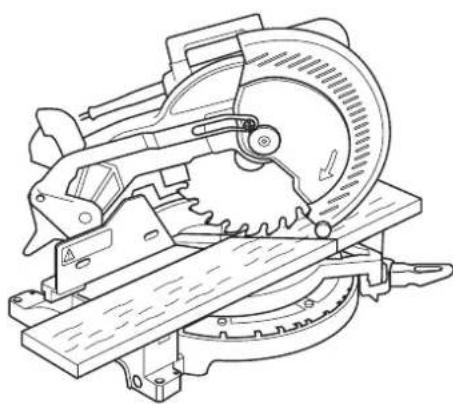
Vertical Straight Cross Cut (fi g. 1, 2, 23)
NOTE: Always use 250 mm saw blades with 30 mm arbor holes to obtain the desired cutting capacities.
- Release the mitre lock lever (e) and depress the mitre detent (t) to release the mitre arm.
- Engage the mitre latch at the 0° position and tighten the mitre lever.
- Place the wood to be cut against the fence (c, v).
- Take hold of the operating handle (a) and depress the head lock up release lever (cc) to release the head.
- Press the trigger switch (I) to start the motor.
- Depress the head to allow the blade to cut through the timber and enter the plastic kerf plate (s).
- After completing the cut, release the switch and wait for the saw blade to come to a complete standstill before returning the head to its upper rest position.
Vertical Mitre Cross-cuts (fi g. 1, 2, 24)
- Loosen the mitre lock lever (e) and depress the mitre detent (t). Move the head left or right to the required angle.
- The mitre detent will automatically locate at 10^ , 15^ , 22.5^ , 31.62^ and 45^ . if any intermediate angle or 50^ is required hold the head firmly and lock by tightening the mitre lock lever.
- Always ensure that the mitre lock lever is locked tightly before cutting.
- Proceed as for a vertical straight cross-cut.

WARNING: When mitring the end of a piece of wood with a small off-cut, position the wood to ensure that the off-cut is to the side of the blade with the greater angle to the fence; i.e. left mitre, off-cut to the right - right mitre, off-cut to the left.
Bevel Cuts (fi g. 1, 2, 25)
Bevel angles can be set from 3^ right to 48^ left and can be cut with the mitre arm set between zero and a maximum of 45^ mitre position right or left.
- Loosen the left side fence clamping knob (k) and slide the upper part of the left side fence (v) to the left as far as it will go. Loosen the bevel clamp handle (p) and set the bevel as desired.
- Tighten the bevel clamp handle (p) firmly.
- Proceed as for a vertical straight cross-cut.
Quality of Cuts
The smoothness of any cut depends on a number of variables, e.g. the material being cut. When smoothest cuts are desired for moulding and other precision work, a sharp (60 tooth carbide) blade and a slower, even cutting rate will produce the desired results.

WARNING: Ensure that the material does not creep while cutting; clamp it securely in place. Always let the blade come to a full stop before raising the arm. If small fibres of wood still split out at the rear of the workpiece, stick a piece of masking tape on the wood where the cut will be made. Saw through the tape and carefully remove tape when finished.
Clamping the Workpiece (fi g. 3)
- Whenever possible, clamp the wood to the saw.
- For best results use the clamp (gg) made for use with your saw. Clamp the workpiece to the fence whenever possible. You can clamp to either side of the saw blade; remember to position your clamp against a solid, flat surface of fence.

WARNING: Always use a material clamp when cutting non-ferrous metals.
Support for Long Pieces (fi g. 3)
- Always support long pieces.
- For best results, use the extension work support (jj) to extend the table width of your saw (available from your dealer as an option). Support long workpieces using any convenient means such as saw-horses or similar devices to keep the ends from dropping.
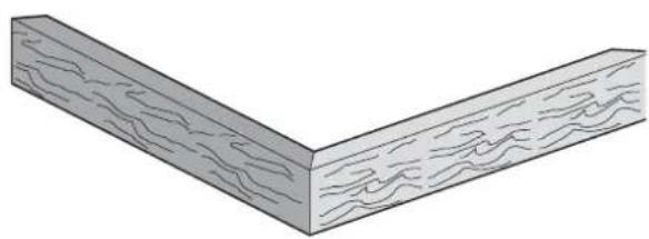
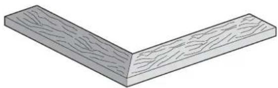
Cutting Picture Frames, Shadow Boxes and Other Four-sided Projects (fi g. 26, 27)
TRIM MOULDING AND OTHER FRAMES
Try a few simple projects using scrap wood until you develop a "feel" for your saw. Your saw is the perfect tool for mitring corners like the one shown in figure 26. The joint shown has been made using either bevel adjustment.
USING BEVEL ADJUSTMENT
The bevel for the two boards is adjusted to 45° each, producing a 90° corner. The mitre arm is locked in the zero position. The wood is positioned with the broad flat side against the table and the narrow edge against the fence.
USING MITRE ADJUSTMENT
The same cut can be made by mitring right and left with the broad surface against the fence.
The two sketches (fig. 26, 27) are for four side objects only. As the number of sides changes, so do the mitre and bevel angles. The chart below gives the proper angles for a variety of shapes, assuming that all sides are of equal length. For a shape that is not shown in the chart, divide 180^ by the number of sides to determine the mitre or bevel angle.
No. of sides Angle mitre or bevel
| 4 | 45^ |
| 5 | 36^ |
| 6 | 30^ |
| 7 | 25.7^ |
| 8 | 22.5^ |
| 9 | 20^ |
| 10 | 18^ |
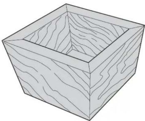
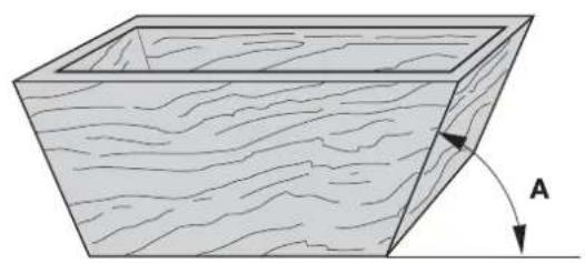
Compound Mitre (fi g. 26–29)
A compound mitre is a cut made using a mitre angle (fig. 27) and a bevel angle (fig. 26) at the same time. This is the type of cut used to make frames or boxes with slanting sides like the one shown in figure 28.

WARNING: If the cutting angle varies from cut to cut, check that the bevel clamp knob and the mitre lock knob are securely tightened. These knobs must be tightened after making any changes in bevel or mitre.
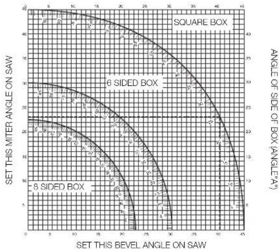
- The chart shown below will assist you in selecting the proper bevel and mitre settings for common compound mitre cuts. To use the chart, select the desired angle "A" (fig. 29) of your project and locate that angle on the appropriate arc in the chart. From that point follow the chart straight down to find the correct bevel angle and straight across to find the correct mitre angle.
line
| SET THIS BEVEL ANGLE ON SAW | SET THIS MITER ANGLE ON SAW | ANGLE OF SIDE OF BOX (ANGLE″A) | | --------------------------- | --------------------------- | ------------------------------ | | 0 | 40 | 40 | | 5 | 38 | 38 | | 10 | 35 | 35 | | 15 | 32 | 32 | | 20 | 28 | 28 | | 25 | 22 | 22 | | 30 | 16 | 16 | | 35 | 10 | 10 | | 40 | 5 | 5 |- Set your saw to the prescribed angles and make a few trial cuts.
• Practice fitting the cut pieces together. - Example: To make a 4 sided box with 25^ exterior angles (angle "A") (fig. 29), use the upper right arc. Find 25^ on the arc scale. Follow the horizontal intersecting line to either side to get the mitre angle setting on the saw (23^) . Likewise follow the vertical intersecting line to the top or bottom to get the bevel angle setting on the saw (40^) . Always try cuts on a few scrap pieces of wood to verify the settings on the saw.
Vernier Scale (fi g. 30–32)
Your saw is equipped with a vernier scale for added precision. For settings that require partial degrees (1/4°, 1/2°, 3/4°), the vernier scale allows you to accurately set mitre angles to the nearest 1/4° (15 minutes). To use the vernier scale follow the steps listed below. As an example, assume that the angle you want to mitre is 24-1/4° right.
- Switch off the mitre saw.
- Set the mitre angle to the nearest whole degree desired by aligning the centre mark in the vernier scale, shown in figure 30, with the whole degree number etched in the mitre scale. Examine figure. 31 closely; the setting shown is 24^ right mitre.
- To set the additional 1/4^ , squeeze the mitre arm lock and carefully move the arm to the right until the 1/4^ vernier mark aligns with the closest degree mark on the mitre scale. In this example, the closest degree mark on the mitre scale happens to be 25^ . Figure 32 shows a setting of 24-1/4^ right mitre.
- When mitring to the right:
- increase the mitre angle by moving the arm to align the appropriate vernier mark with the closest mark on the mitre scale to the right.
– decrease the mitre angle by moving the arm to align the appropriate vernier mark with the closest mark on the mitre scale to the left.
- When mitring to the left:
- increase the mitre angle by moving the arm to align the appropriate vernier mark with the closest mark on the mitre scale to the left.
– decrease the mitre angle by moving the arm to align the appropriate vernier mark with the closest mark on the mitre scale to the right.
Cutting Base Mouldings
The cutting of base moulding is performed at a 45° bevel angle.
• Always make a dry run without power before making any cuts.
- All cuts are made with the back of the moulding laying flat on the saw.
INSIDE CORNER
Left side
- Position the moulding with top of the moulding against the fence.
- Save the left side of the cut.
Right side
- Position the moulding with the bottom of the moulding against the fence.
- Save the left side of the cut.
OUTSIDE CORNER
Left side
- Position the moulding with the bottom of the moulding against the fence.
- Save the right side of the cut.
Right side
- Position the moulding with top of the moulding against the fence.
2 Save the right side of the cut.
Cutting Crown Mouldings
The cutting of crown moulding is performed in a compound mitre. In order to achieve extreme accuracy, your saw has pre-set angle positions at 31.62° mitre and 33.85° bevel. These settings are for standard crown mouldings with 52° angles at the top and 38° angles at the bottom.
- Make test cuts using scrap material before doing the final cuts.
- All cuts are made in a left bevel and with the back of the moulding against the base.
INSIDE CORNER
Left side
- Top of the moulding against the fence.
- Mitre right.
- Save the left side of the cut.
Right side
- Bottom of the moulding against the fence.
- Mitre left.
- Save the left side of the cut.
OUTSIDE CORNER
Left side
- Bottom of the moulding against the fence.
- Mitre left.
- Save the left side of the cut.
Right side
- Top of the moulding against the fence.
- Mitre right.
- Save the right side of the cut.
Special Cuts
- All cuts are made with the material secured to the table and against the fence. Be sure to properly secure workpiece.
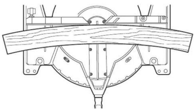
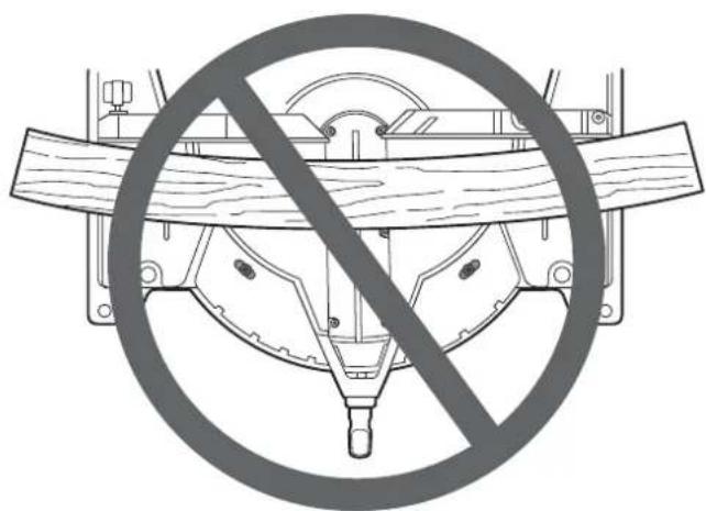
BOWED MATERIAL
When cutting bowed material always position it as shown in figure 34 and never like that shown in figure 35. Positioning the material incorrectly will cause it to pinch the blade near the completion of the cut.
CUTTING PLASTIC PIPE OR OTHER ROUND MATERIAL
Plastic pipe can be easily cut with your saw. It should be cut just like wood and clamped or held firmly to the fence to keep it from rolling. This is extremely important when making angle cuts.
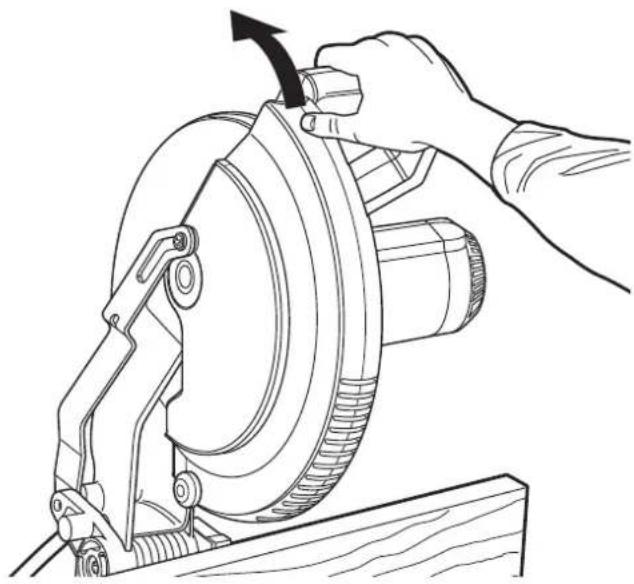
CUTTING LARGE MATERIAL
Occasionally a piece of wood will be too large to fit beneath the blade guard. A little extra height can be gained by rolling the guard up out of the way, as shown in figure 36. Avoid doing this as much as possible, but if need be, the saw will operate properly and make the bigger cut. NEVER TIE, TAPE, OR OTHERWISE HOLD THE GUARD OPEN WHEN OPERATING THIS SAW.

Dust Extraction (fi g. 2, 3)
• Fit the dustbag (ff) onto the dust spout (n).

WARNING! Whenever possible, connect a dust extraction device designed in accordance with the relevant regulations regarding dust emission.
Connect a dust collection device designed in accordance with the relevant regulations. The air velocity of externally connected systems shall be 20 m/s ±2 m/s. Velocity to be measured in the connection tube at the point of connection, with the tool connected but not running.
Transporting (fi g. 4)
In order to conveniently carry the mitre saw, a carrying handle (a) has been included on the top of the saw arm.
- To transport the saw, lower the arm and depress the lock down pin (o).
- Always use the carrying handle (a) or the hand indentations (r) shown in figure 4 to transport the saw.
MAINTENANCE
Your DEWALT power tool has been designed to operate over a long period of time with a minimum of maintenance. Continuous satisfactory operation depends upon proper tool care and regular cleaning.

NG: To reduce the risk of injury, turn unit off and disconnect machine from power source before installing and removing accessories, before adjusting or changing set-ups or when making repairs. Be sure the trigger switch is in the OFF position. An accidental start-up can cause injury.

Lubrication
Closed-type, grease-sealed ball bearings are used throughout. These bearings have sufficient lubrication packed in them at the factory to last the life of the chop saw.

Cleaning
Before use, carefully check the upper blade guard, movable lower blade guard as well as the dust extraction tube to determine that it will operate properly. Ensure that chips, dust or workpiece particle cannot lead to blockage of one of the functions.
In case of workpiece fragments jammed between saw blade and guards disconnect the machine from the power supply and follow the instructions given in section Mounting the Saw Blade. Remove the jammed parts and reassembling the saw blade.

WARNING: Blow dirt and dust out of the main housing with dry air as often as dirt is seen collecting in and around the air vents. Wear approved eye protection and approved dust mask when performing this procedure.

WARNING: Never use solvents or other harsh chemicals for cleaning the non-metallic parts of the tool. These chemicals may weaken the materials used in these parts. Use a cloth dampened only with water and mild soap. Never let any liquid get inside the tool; never immerse any part of the tool into a liquid.

WARNING: To reduce the risk of injury, regularly clean the table top.

WARNING: To reduce the risk of injury, regularly clean the dust collection system.
Optional Accessories

WARNING: Since accessories, other than those offered by DEWALT, have not been tested with this product, use of such accessories with this tool could be hazardous. To reduce the risk of injury, only DEWALT, recommended accessories should be used with this product.
LED WORKLIGHT WARNING:
LED RADIATION: DO NOT STARE INTO BEAM
CLASS 2 LED PRODUCT
MAXIMUM OUTPUT POWER
$$ P = 9. 2 \mathrm{mW}; \quad \lambda_ {\text { peak }} = 4 5 6 \mathrm{nm} $$
IEC 60825-1:1:1993; +A1:1997; +A2:2001
Consult your dealer for further information on the appropriate accessories.
Protecting the Environment

Separate collection. This product must not be disposed of with normal household waste.

Should you find one day that your DEWALT product needs replacement, or if it is of no further use to you, do not dispose of it with household waste. Make this product available for separate collection.

Separate collection of used products and packaging allows materials to be recycled and used again. Re-use of recycled materials helps prevent environmental pollution and reduces the demand for raw materials.
Local regulations may provide for separate collection of electrical products from the household, at municipal waste sites or by the retailer when you purchase a new product.
DEWALT provides a facility for the collection and recycling of DEWALT products once they have reached the end of their working life. To take advantage of this service please return your product to any authorised repair agent who will collect them on our behalf.
You can check the location of your nearest authorised repair agent by contacting your local DEWALT office at the address indicated in this manual. Alternatively, a list of authorised DEWALT repair agents and full details of our after-sales service and contacts are available on the Internet at: www.2helpU.com.
GUARANTEE
DEWALT is confident of the quality of its products and offers an outstanding guarantee for professional users of the product. This guarantee statement is in addition to and in no way prejudices your contractual rights as a professional user or your statutory rights as a private non-professional user. The guarantee is valid within the territories of the Member States of the European Union and the European Free Trade Area.
• 30 DAY NO RISK
SATISFACTION GUARANTEE •
If you are not completely satisfied with the performance of your DEWALT tool, simply return it within 30 days, complete with all original components, as purchased, to the point of purchase, for a full refund or exchange. The product must have been subject to fair wear and tear and proof of purchase must be produced.
• ONE YEAR FREE SERVICE CONTRACT •
If you need maintenance or service for your DEWALT tool, in the 12 months following purchase, it will be undertaken free of charge at an authorised DEWALT repair agent. Proof of purchase must be produced. Includes labour. Excludes accessories and spare parts unless failed under warranty.
• ONE YEAR FULL WARRANTY •
If your DEWALT product becomes defective due to faulty materials or workmanship within 12 months from the date of purchase, DEWALT guarantees to replace all defective parts free of charge or – at our discretion – replace the unit free of charge provided that:
• The product has not been misused;
• The product has been subject to fair wear and tear;
• Repairs have not been attempted by unauthorised persons;
• Proof of purchase is produced;
- The product is returned complete with all original components.
If you wish to make a claim, contact your seller or check the location of your nearest authorised DEWALT repair agent in the DEWALT catalogue or contact your DEWALT office at the address indicated in this manual. A list of authorised DEWALT repair agents and full details of our after-sales service is available on the Internet at: www.2helpU.com.
INGLETADORA DW713, DW713XPS
¡Enhorabuena!
PRODUCTO LED DE CLASE 2
SCIE A ONGLET DW713, DW713XPS
Félicitations !
(Isolation double) -outils
TRONCATRICE DW713, DW713XPS
Congratulazioni!
POTENZA MAX DI USCITA
$$ P = 9. 2 m W; $$
$$ \lambda_ {\text { peak }} = 4 5 6 \mathrm{nm} $$
IEC 60825-1:1:1993; +A1:1997; +A2:2001
VERSTEKZAAGMACHINE DW713, DW713XPS
Gefeliciteerd!
Vice President Engineering and Product Development
RKLICHT WAARSCHUWING:
LED STRALING: KIJK NIET RECHTSREEKS NAAR DE STRAAL
KLASSE 2 LEDPRODUCT
MAXIMALE STROOMVERMOGEN
P = 9,2 mW:
_piec = 456 nm
IEC 60825-1:1:1993; +A1:1997; +A2:2001
GJÆRSAG DW713, DW713XPS
Gratulerer!
SJEKKING OG JUSTERING AV BLADET TIL BORDET (FIG. 13–18)
LED-PRODUKT AV KLASSE 2
MAKSIMAL UTGANGSSTYRKE
P = 9,2 mW; topp = 456nm
IEC 60825-1:1:1993; +A1:1997; +A2:2001
KATKAISU- JA JIIRISAHA DW713, DW713XPS
Onnittelut!
Vice President Engineering and Product Development
DEWALT, Richard-Klinger-Strasse 11,
D-65510, Idstein, Germany
29.12.2009
Turvaohjeet

GERINGSÅG DW713, DW713XPS
Gratulerar!
DATUMKODPLACERING (FIG. 1)
KLASS 2 LYSDIODPRODUKT
MAXIMAL
UTEFFEKT
P = 9.2 mW;
_peak = 456 nm
IEC 60825-1:1:1993; +A1:1997; +A2:2001
DAIRE TESTERE DW713, DW713XPS
Tebrikler!
P = 9,2mW; peak = 456nm
IEC 60825-1:1:1993; +A1:1997; +A2:2001