
UU240F - Saw HiKOKI - Free user manual and instructions
Find the device manual for free UU240F HiKOKI in PDF.

User questions about UU240F HiKOKI
0 question about this device. Answer the ones you know or ask your own.
Ask a new question about this device
Download the instructions for your Saw in PDF format for free! Find your manual UU240F - HiKOKI and take your electronic device back in hand. On this page are published all the documents necessary for the use of your device. UU240F by HiKOKI.
USER MANUAL UU240F HiKOKI
natural_image
Technical line drawing of a tripod-mounted surveying instrument with adjustable legs and a central dial (no text or symbols)
en Handling instructions
de Bedienungsanleitung
fr Mode d'emploi
it Istruzioni per l'uso
nl Gebruiksaanwijzing
es Instrucciones de manejo
pt Instruções de uso
SV Bruksanvisning
da Brugsanvisning
no Bruksanvisning
fi Käyttöohjeet
SAFETY INSTRUCTIONS AND INSTRUCTION MANUAL
WARNING
Improper or unsafe use of this miter saw stand can result in death or serious bodily injury!
This manual contains important information about product safety. Please read and understand this manual BEFORE using the miter saw stand. Please keep this manual available for users and owners before they use the miter saw stand. This manual should be stored in a safe place.
Definition of Signal Words 7
General Safety 7
Miter Saw Stand Safety 8
Carton Contents 9
Product Specifications 11
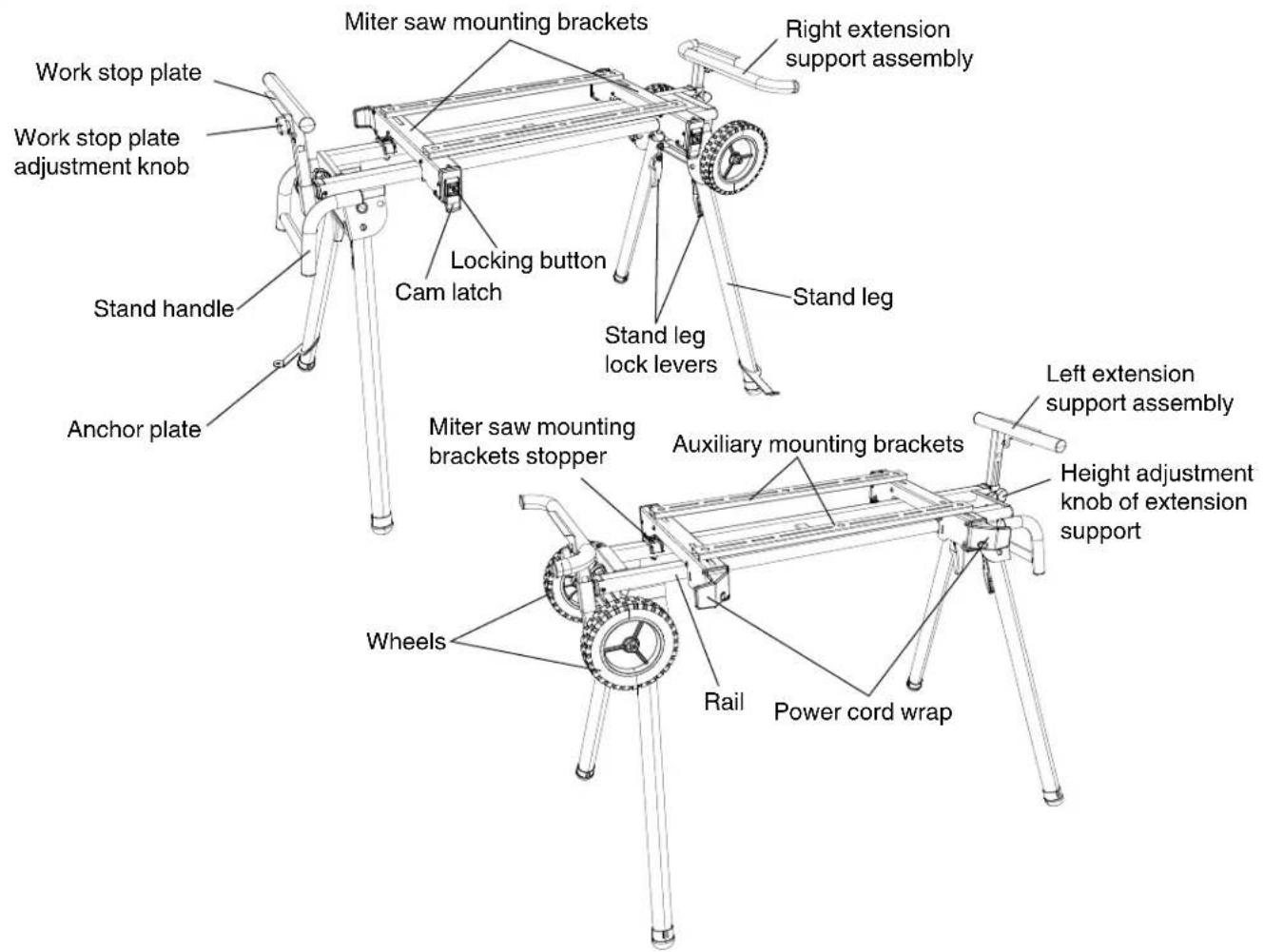
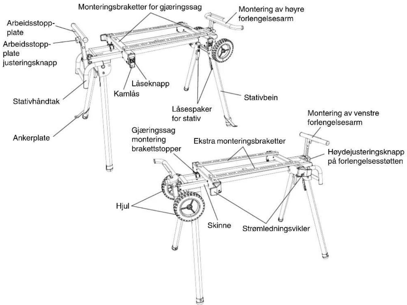
Know Your Stand 11
SECTION
Assembly 12
Adjustment 16
Operation 17
Maintenance 18
Parts List 145
INHALTSVERZEICHNIS
Deutsch
KAPITEL
Productspecifications 62
- WARNING indicates a hazardous situation that if not avoided, could result in death or serious injury.
- CAUTION indicates a hazardous situation that if not avoided, could result in minor or moderate injury, or may cause machine damage.
- NOTE emphasizes essential information.
GENERAL SAFETY

WARNING
GENERAL SAFETY INFORMATION
Read and understand all warnings and operating instructions before using any tool or equipment. When using tools or equipment, basic safety precautions should always be followed to reduce the risk of personal injury. Improper operation, maintenance or modification of tools or equipment could result in serious injury and property damage. There are certain applications for which tools and equipment are designed. Do not modify the stand in any manner, or use the stand for unintended purpose.

WARNING
- Failure to follow these rules may result in serious personal injury.
- To reduce the risk of injury, keep both hands on handle when raising and lowering the stand.
- Before folding the stand, the miter saw MUST be removed from the stand.
- Use only with HiKOKI mounting brackets. Mounting brackets offered by other than HiKOKI have not been tested with this stand and use of them could be hazardous.
Please read and understand this entire manual before attempting to assemble, operate or install the product. These safety instructions are not meant to cover every possible condition that could occur.
MITER SAW STAND SAFETY
SAFETY INSTRUCTIONS FOR USING THE MITER SAW STAND
- Keep children away. All visitors should be kept at a safe distance from the work area.
• Always keep work area clean. Cluttered areas and benches invite accidents.
- Before you use the stand, make sure no parts of the stand are damaged or deformed.
• Before you use the stand, make sure all the parts or components of the stand are properly installed.
- Don't use in dangerous environment. Don't use the stand in damp or wet locations, or expose them to rain. Keep work area well lighted.
- Always use the stand on a flat and level surface. Do not use it at an uneven or unstable surface. Also, do not use the stand on slippery surface. It will greatly reduce the stand loading capacity.
- The stand is designed to be used as a stand for HiKOKI miter saws and has a capacity of up to 181 kg. The total weight of the miter saw and workpiece must not exceed the capacity of this stand. Any misuse or abuse can result in product damage or personal injury.
- Do not sit or stand on the stand. Do not hang or put anything on it other than the miter saw on the stand.
- Do not modify the stand in any manner, or do not use the stand for any purpose other than for mounting a HiKOKI miter saw.
- The stand should be used only for HiKOKI miter saws with a blade diameter up to 305 mm. However, the stand will not work with C12FSA.
- The miter saw should be firmly mounted with the stand as per the instruction manual.
- Align the position and balance of the miter saw as per this instruction manual after mounting the miter saw on the stand.
• Take care during the raising and lowering of the stand to reduce the hazard of pinching hands and fingers.
- Disconnect the power plug from the receptacle when mounting or dismounting the miter saw from the stand.
- Mount the miter saw on the stand with the help of two or more people for your safety.
- When you mount the miter saw on the stand, hold the miter saw firmly by hands until the mounting bracket cam latches tightly secured to prevent the miter saw from falling down from the stand rails.
- After mounting the miter saw on the stand, make sure the stand will not fall over or be unintentionally moved by vibration, wind, impact or other foreseeable external forces. If this cannot be fulfilled, then stability shall be obtained by special safety measures. For example, securely anchor to the stand to the ground or foundation.
- Occasionally check that the stand and the miter saw, making sure the mounting of the miter saw is still tight. A loose stand is unstable and may shift while in use causing serious injury.
• Before operating the mounted miter saw, read carefully the instruction manual for the miter saw.
- Before operating the miter saw, confirm that the cam latches on the both mounting brackets are firmly fastened so that the miter saw is securely mounted on the stand.
- To prevent the miter saw from falling over from the stand, neatly layout the power cable on the ground to prevent operator or by standers from getting caught up by the cable.
- Wear proper apparel. Do not wear loose clothing, gloves, neckties, rings, bracelets, or other jewelry which may get caught in moving parts. Nonslip footwear is recommended. Wear protective hair covering to contain long hair.
- Always wear eye protection with side shields that meets the requirements of EN166 when working with the miter saw to prevent eye injury. Ordinary eyeglasses do not provide adequate protection because they do not contain impact resistant safety glass. Also, use a face mask for additional safety and wear a dust mask if the cutting operation produces dust.
- Don't overreach. Keep proper footing and balance at all times.
- When cutting a long piece of wood, be careful about the material supporting position because the cut material may lose its balance and fall down from the stand. Also, if workpiece is placed beyond the work support, the leg on the other side of the stand may be suddenly lifted up due to unbalance of weight. To prevent such occurrence, firmly hold the opposite side and use extra support before starting cutting operation.
- To detach the miter saw from the stand, confirm the cutting head is pulled forward and locked in the down position, then unlock the mounting bracket cam latches while holding the miter saw firmly by hands to prevent the miter saw from falling down from the stand rails. Remove the miter saw with the mounting brackets carefully with the help of two or more people.
- When transporting the stand in a vehicle, securely tie it down to prevent movement and possible damage.
- To reduce the risk of injury, periodically check that all fasteners are attached and adjusted according to the assembly instructions included in this manual.
- When service the stand, use only identical HiKOKI replacement parts. Repairs should be conducted only by a HiKOKI authorized service center.
SAVE THESE INSTRUCTIONS AND MAKE THEM AVAILABLE TO OTHER USERS AND OWNERS OF THIS STAND.
CARTON CONTENTS
UNPACKING YOUR STAND
This product requires assembly.
- Remove the stand and all parts from the carton.
- Place the stand on the ground.
- Separate all parts from the packing material. Check each one with the list below and illustration on page 10 to make certain all items are accounted before discarding any packing material.

WARNING
If any part is missing or damaged, do not attempt to assemble the stand until the missing or damaged part is correctly replaced.
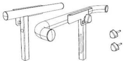
TABLE OF LOOSE PARTS
ITEM DESCRIPTION QUANTITY
| A Stand 1 | ||
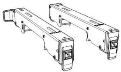
| B Miter saw mounting bracket 2 | ||
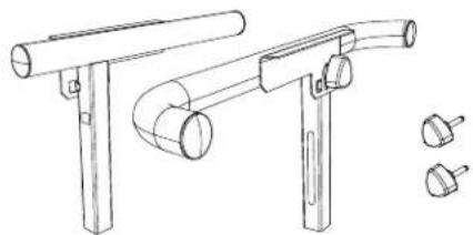
| C Extension arm support assembly 2 | ||
| D Auxiliary mounting bracket 2 | ||
| E Bracket Stopper hardware bag 1 | ||
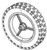
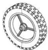
| F Wheel 2 | ||
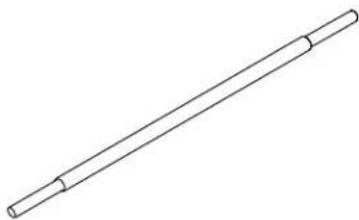
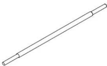
| G Wheel shaft | 1 | |
| H Wheel hardware bag | 1 | |
| I | Auxiliary mounting brackets hardware bag | 1 |
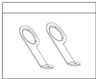
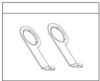
| J | Anchor plate | 2 |
NOTE: If any part is missing or damaged, do not attempt to assemble the stand until the missing or damaged part is correctly replaced.
UNPACKING AND CHECKING CONTENTS

natural_image
Technical line drawing of a mechanical support frame assembly (no text or symbols)A

natural_image
Technical line drawing of two mechanical components with mounting brackets and mounting holes (no text or symbols)B

natural_image
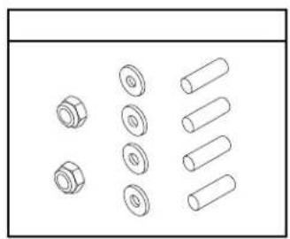
Technical line drawing of a mechanical support bracket with two cylindrical components and three separate mounting holes (no text or symbols)C

natural_image
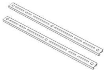
Two parallel metal beams with evenly spaced cutouts and circular holes, shown in isometric view (no text or symbols)D

natural_image
Technical line drawing of two mechanical components with bolts and brackets (no text or symbols)E


F

natural_image
Simple line drawing of a cylindrical rod or rod with two ends (no text or symbols)G
natural_image
Technical line drawing of mechanical parts including bolts, cylinders, and flanges (no text or symbols)H
natural_image
Collection of mechanical parts including screws, plates, and diamonds arranged in a grid (no text or symbols)|

natural_image
Two identical metal loop components with mounting holes, shown in line drawing style (no text or symbols)J
PRODUCT SPECIFICATIONS
| Stand height (ground to saw mounting brackets) 887 mm | |
| Stand bed size 1067 mm x 216 mm | |
| Size of the folded stand 1317 mm (L) x 465 mm (W) x 321 mm (H) | |
| Size of the extended stand 1317 mm (L) x 785 mm (W) x 933 mm (H) | |
| Diameter of wheel 203 mm | |
| Maximum weight load of stand | 181 kg*Do not place heavier load on this stand. |
| Maximum length of the material to be cut | 2426 mm*Do not apply a longer material. |
| Weight of stand 22.7 kg |
The stand should be used only for HiKOKI miter saws with a blade diameter up to 305 mm. However, the stand will not work with C12FSA.
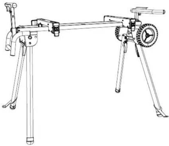
KNOW YOUR STAND
ASSEMBLY
TOOLS NEEDED FOR ASSEMBLY
The stand needs to be assembled by the user. Tools needed for assembly are:
10 mm wrench, two 17 mm wrenches, 5 mm hex wrench and a Philips screwdriver.
ASSEMBLY INSTRUCTIONS

WARNING
For your own safety, never connect miter saw plug to any power source outlet until all assembly and adjustment steps are completed, and you have read and understood the safety and operating instructions.
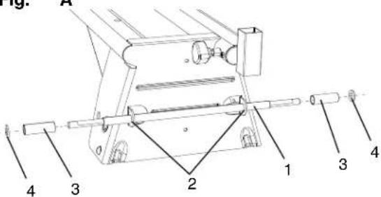
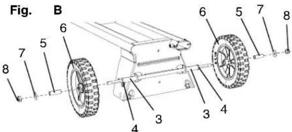
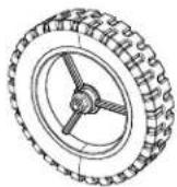
INSTALLING THE WHEELS (FIG. A, B)
- Unfold the stand with the instruction of "SETTING UP THE STAND" on page 17.
- Insert the wheel shaft (1) into the wheel shaft holder (2). (Fig. A)
- Attach one long sleeve (3) and one washer (4) to each side of the wheel shaft (1). (Fig. A)
NOTE: Adjust the wheel shaft (1) making sure the shaft is the same length on both ends of the stand. - Insert one shorter sleeve (5) into each wheel (6), and attach the wheels (6) to the wheel shaft (1). (Fig. B)
NOTE: The side with more ribs on the wheel should face inward. - Put the washers (7) and lock nuts (8) on the two ends of the wheel shaft (1) and tighten the wheels by using two 17 mm wrenches. (Fig. B)
NOTE: Do not overtighten, or wheels will not turn.
Fig.
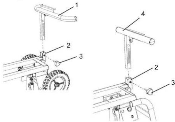
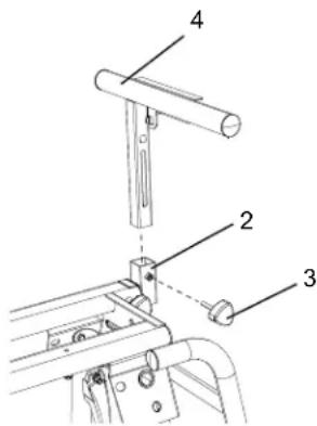
INSTALLING THE EXTENSION SUPPORT ASSEMBLY (FIG. C)
- Insert the bent extension support (1) into the wheel side extension support arm (2), and secure with the height adjustment knob (3).
- Insert the straight extension support (4) into the handle side extension support arm (2), and secure with the height adjustment knob (3).
Fig.
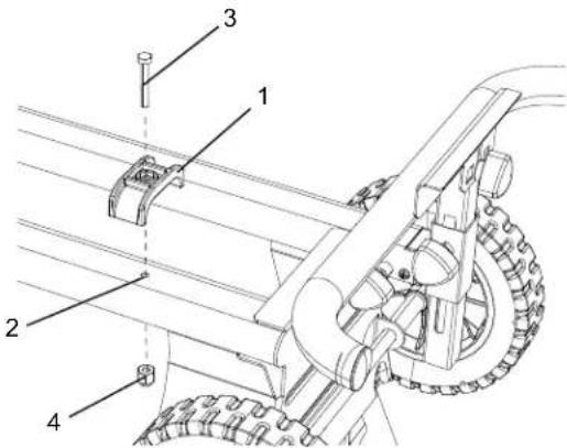
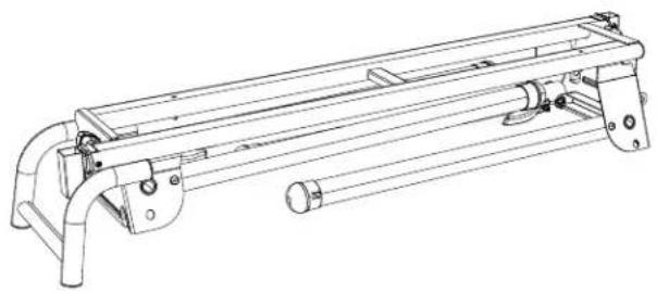
INSTALLING THE BRACKET STOPPERS (FIG. D)
- Place one bracket stopper (1) on one of the rail, and align the hole on the bracket stopper (1) with the hole (2) on the rail.
- Insert one lock bolt (3) through the hole of the bracket stopper and the hole on the rail. Tighten with the stop nut (4) using the 10 mm wrench.
- Repeat above steps for installing the other bracket stopper on the other end of the rail.
Fig.
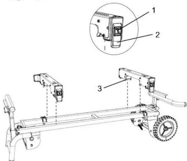
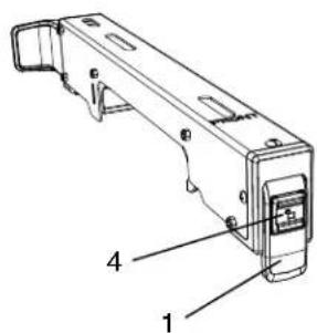
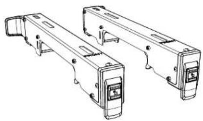
INSTALLING THE SAW MOUNTING BRACKETS (FIG. E)
- Press the locking button (1) and lift up on the cam latch (2).
- Place the rear holding clamp (3) on the back rail of the stand, and then lower the front end of the saw mounting bracket over the front rail of the stand.
NOTE: Place the saw mounting brackets on the interior side of the bracket stoppers.
- Slide the saw mounting bracket to the desired position, and then push down the cam latch (2) to lock.
- Repeat the above steps for the other saw mounting bracket.
Fig. E
INSTALLING THE ANCHOR PLATES (FIG. F, G)
Please follow the steps below to install the anchor plates to make the stand stable for operation.
-
Insert an anchor plate (1) through one stand leg (2) directly, and fi x the anchor plate (1) to the ground surface with an anchor (screw, bolt, peg etc.) which is suitable for the type of ground surface (soil, wood flooring, concrete etc.).
-
Insert the other anchor plate to diagonal stand leg as shown in Fig. G. Fix the anchor plate to the ground in the same way.

WARNING
- Ensure that both anchor plates are fixed firmly to the ground and the stand is stable.
- Appropriate way to fix the anchor plates may differ according to the type of ground surface. If the anchor plates are not firmly fixed and the stand is unstable, please take appropriate measures to fix the anchor plates.
Fig. F
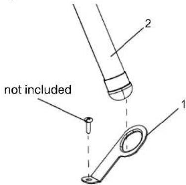
Fig. G
natural_image
Line drawing of a tripod-mounted optical bench with a wheel and lever (no text or symbols)MOUNTING THE MITER SAW TO THE STAND

WARNING
- Do not mount the miter saw to the stand without first ensuring the stand is extended fully and locked securely. To set up the stand, follow the instruction in section "SETTING UP THE STAND" on page 17. Failure to do so may result in possible injury and damage to the stand and the miter saw.
- Always use the saw mounting brackets and auxiliary mounting bracket together when mounting the miter saw to the stand.
- Before operating the mounter miter saw, read carefully the instruction manual for the miter saw.
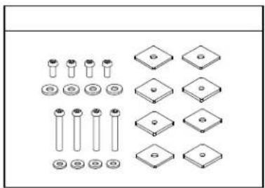
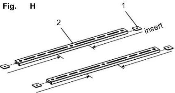
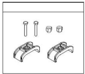
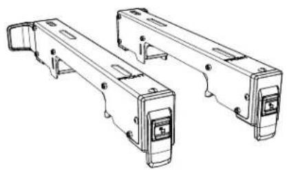
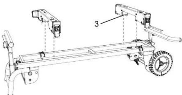
Using auxiliary mounting brackets (provided) (FIG. H, I, J, K)
- Insert two square nuts (1) into the slot on each end of both auxiliary mounting brackets (2) and slide them to the middle of the auxiliary mounting brackets. (Fig. H)
- Insert two washers (3) into the auxiliary mounting bracket (2) and align with the hole at the end of the auxiliary mounting brackets (2). (Fig. I)
- To mount the auxiliary mounting bracket (2) onto the saw mounting brackets (4), insert the screws (5) through the inserted washers (3) into the square nuts (1) below the saw mounting bracket (4) for fixing each end of the auxiliary mounting bracket (2) by using 5 mm hex wrench. (Fig. I)
- Repeat the above steps of 2 & 3 for assembling the other auxiliary mounting bracket.
NOTE: Do not tighten the four screws (5) securely at this time.

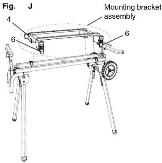
- Make sure the cam latches (6) of the saw mounting brackets (4) are in the unlocked position. (Fig. J)
- Lower the rear and front ends of the mounting brackets assembly onto the rear and front rails of the stand. The front holding clamps of the saw mounting brackets (4) must seat fully on the front rail. Make sure that the saw mounting brackets are positioned at right angle to the front and rear rails. (Fig. J)
- Lock the mounting brackets assembly in position by pressing down on the two cam latches (6). (Fig. J)
WARNING
- Ensure that the saw mounting brackets can be clamped securely on the stand before mounting the miter saw.
- To reduce the risk of injury, ensure all bolts and nuts are properly tightened and all mechanisms properly function after completing assembling and before each use.
WARNING
- The cutting head on all sliding miter saws must be locked in both the forward and down positions before any attempt is make to mount to the stand. Failure to do so may result in serious personal injury.
- Stay alert. The stand and miter saw may fall down during this procedure and cause serious injury.
- Do not use the miter saw on the stand when the legs of stand are folded.
-
Layout the power cable neatly to prevent the power cable causing the stand to tip over when performing the cutting operation.
-
Unplug the miter saw and lock the cutting head to its down position. If the miter saw has a sliding rail, lock the cutting head in the down and forward position. Put the miter saw on the mounting brackets assembly.
NOTE: For your own safety, position the miter saw on the brackets with the help of two or more people.
-
Slide the square nuts (1) to the slots of the auxiliary mounting brackets (2) and align to the mounting holes of the miter saw. (Fig. K)
-
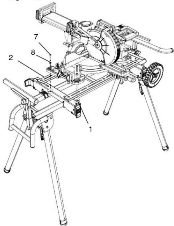
Insert the bolts (7) through the washers (8), the mounting holes of the miter saw and the slots of the auxiliary mounting brackets (2) into the square nuts (1) to mount and lock the miter saw to the auxiliary mounting brackets (2). (Fig. K)
NOTE: Adjust the position of the auxiliary mounting brackets as close as to the front end of the saw mounting brackets.
- Tighten all bolts (7) using 5 mm hex wrench.
- After securely mounting the miter saw, unlock the hold-down latch of the miter saw and carefully move the cutting head up and down. If the stand tends to fall down, reposition the miter saw.
- Unlock the slide carriage lock knob of the miter saw and carefully slide the cutting head forward. If the stand tends to fall down, reposition the miter saw for more stable position on the brackets.
- Carefully perform sliding movement test at the maximum miter and bevel angles to ensure the stability of the stand and the miter saw.

WARNING
- Do not mount the miter saw front side back to the stand. The miter saw should be mounted as the wheel side of the stand comes to right side of the miter saw.
- When you dismount the miter saw, remove the miter saw together with the mounting brackets assembly, so that you can put the miter saw and the mounting brackets assembly all together for use next time. Be sure to have assistance of two or more people when you mount or dismount the miter saw.
Fig.
ADJUSTMENT

WARNING
To reduce the risk of serious personal injury, turn off and disconnect the machine from power source outlet before installing and removing mounting brackets, making adjustment or doing repairment. An unintentional start-up can cause injury.
ADJUSTMENT INSTRUCTIONS
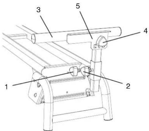
ADJUSTING THE EXTENSION SUPPORTS (FIG. L)
The extension support assembly helps keep the workpiece level and stable during cutting operations.
- Loosen the lock knob (1) and slide the extension arm to the desired length. Tighten the lock knob (1).
- Loosen the height adjustment knob (2) to adjust the extension support assembly (3) to the desired height and then tighten the knob (2).
- Repeat for the other extension support.
- If repetitive cutting is required, loosen the plate adjustment knob (4) to adjust the work stop plate (5) to the desired height, and then tighten.
Fig. L
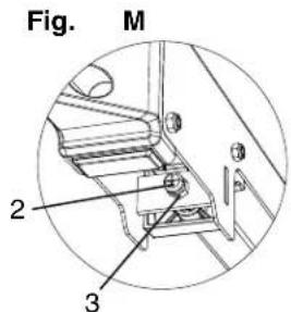
ADJUSTING THE SAW MOUNTING BRACKETS (FIG. M)
If the saw mounting brackets can slide over the top rails or be removed from the top rails when the bracket cam latches (1) are locked, the bracket adjustment screws (2) need to be tightened. If the saw mounting brackets will not fit over the top rails, the bracket adjustment screws need to be loosened.
NOTE: The miter saw should be removed from the mounting brackets before attempting to tighten or loosen the bracket adjustment screws (2).
- Loosen the lock nut (3) using a 10 mm wrench.
- Turn the adjustment screw (2) by using a Phillips screwdriver. Turn the screw clockwise to tighten the bracket, and turn counterclockwise to loosen it.
NOTE: If the cam latch of the saw mounting bracket cannot easily be pushed down into the lock position, the adjustment screw is too tight. Do not force the cam latch into the lock position. Loosen the adjustment screw (2) to adjust it.
-
Press the locking button (4) and lift up the cam latch (1) so the front holding clamp is fully extended.
-
Install the rear holding clamp on the back rail of the stand, then lower the front holding clamp over the front rail of the stand to seat the bracket fully over the rails.
-
Lock the bracket into place and make sure there is no movement.

WARNING
Ensure the saw mounting brackets is placed perpendicular to the top rails to prevent causing potential loosening of the adjustment screw when perform cutting operation.
-
When the tension adjustment is completed, tighten the lock nut (3) to secure.
-
Repeat the above steps for the other saw mounting bracket.
OPERATION
OPERATION INSTRUCTIONS

WARNING
Take care when setting up and folding the stand to reduce the hazard of pinching hands and fingers.
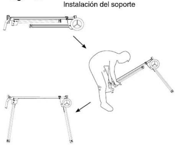
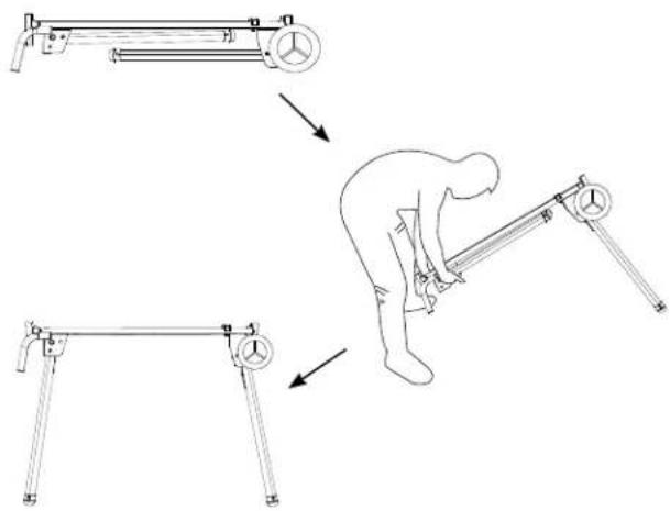
SETTING UP THE STAND (FIG. N, O)
-
First lift up wheel side of stand, and unfold the stand leg (1) by grasping the stand leg lock lever (2) to release and moving the stand leg to the up position. The location pin should be locked into the lower slot (3). (Fig. N)
-
Repeat step 1 to release the other stand leg on the wheel side of stand, and then rest the right side of the stand onto the floor. (Fig. O)

WARNING
To properly lock the stand legs, the lock lever (2) MUST be secured in the slot on the stand legs.
- Repeat step 1-2 for unfolding the stand legs on the handle side of the stand.

WARNING
- Do not mount the miter saw unless the stand top is securely locked.
- Ensure the stand is stable and level before operating the miter saw to prevent the injury. Set up the stand on a level area so that all four legs are touching the ground.
Fig. N

Fig. O
Setting up the stand

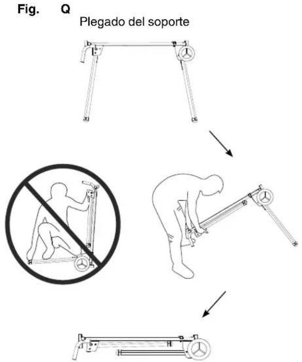
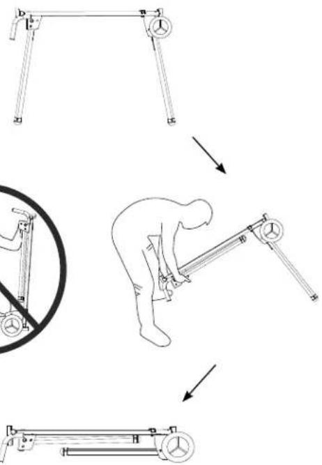
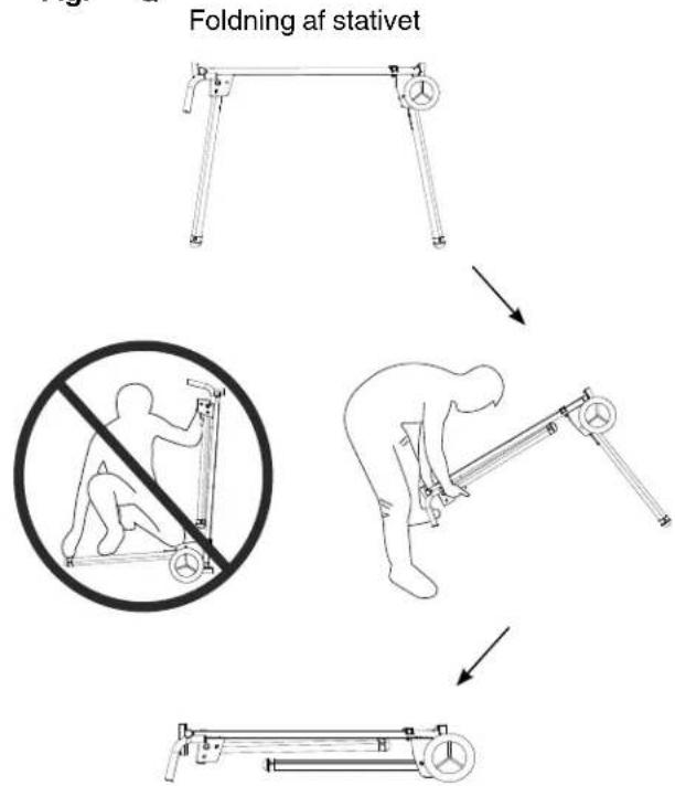
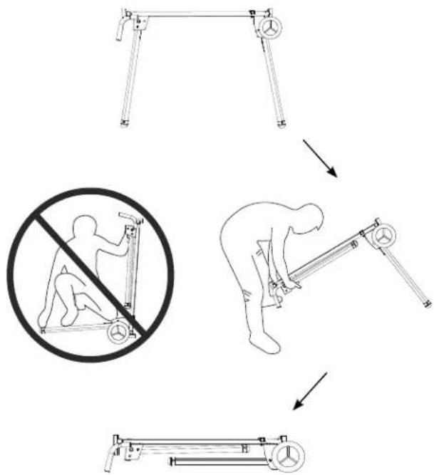
FOLDING THE STAND (FIG. P, Q)

WARNING
- Before folding the stand, remove the miter saw from the stand together with the mounting brackets with the help of two or more people.
-
When folding the stand legs, do not position the wheels on the ground to avoid sudden movement of the stand. (Fig. Q)
-
Lift up the handle side of the stand and fold the stand leg (1) by releasing the stand leg lock lever (2) into the higher slot (3). (Fig. P)
NOTE: To avoid pinching fingers when folding the stand, please stand at the stand handle end of the stand. (Fig. Q)
-
Repeat step 1 to fold the other stand leg on the handle side of stand, and then rest the handle side of the stand onto the floor. (Fig. Q)
-
Repeat step 1-2 for folding the stand legs of wheel side of the stand.
Fig. P
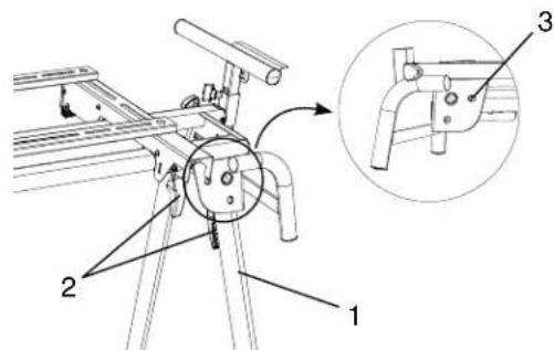
Fig.
Q

flowchart
graph TD
    A["Folding the stand"] --> B["Person using no leg press"]
    B --> C["Person performing exercise"]
    C --> D["Actively folding the stand"]
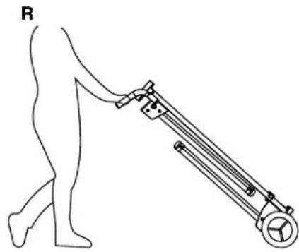
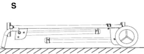
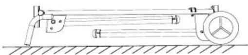
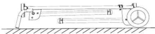
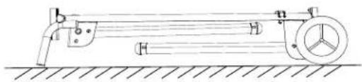
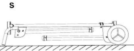
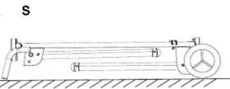
TRANSPORTATION AND STORAGE (FIG. R, S)
Fold the four stand legs using the instructions in section "FOLDING THE STAND" on page 17, hold the stand handles with both hands and slowly raise the stand for transportation and storage. (Fig. R)

WARNING
- Do not transport the unfolded stand with a miter saw mounted on it.
- When transporting the stand in a vehicle, securely tie it down to prevent movement and possible damage.
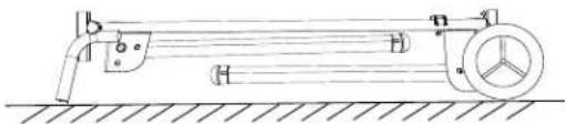
- When storing the stand, make sure that the miter saw is dismounted from the stand and the stand is lying down fl at on a stable surface. Never store the stand in upright position or lean it against wall. (Fig. S)
Fig.
natural_image
Line drawing of a person pushing a long cylindrical device with wheels (no text or symbols)Fig. S
natural_image
Technical line drawing of a mechanical device with pulleys and a wheel, no text or symbols presentMAINTENANCE

WARNING
- When service the stand, use only identical HiKOKI replacement parts. Use any other parts may cause hazards or product damage.
Repairs should be conducted only by a HiKOKI authorized service center. - Always wear safety goggles or safety glasses with side shields and dust mask during power tool operation or when blowing dust.
- Occasionally check the saw mounting brackets, making sure the mounting brackets are tight by following "ADJUSTING THE SAW MOUNTING BRACKETS" on page 16.
GENERAL MAINTENANCE
Remove the miter saw when servicing or cleaning the stand. Use clean cloths to remove dirt, dust, oil, grease and etc. Avoid using solvents when cleaning plastic parts. Most plastics are susceptible to damage from various types of commercial solvents and may be damaged by their use.

WARNING
Do not use the brake fluids, gasoline, petroleum-based products, penetrating oils and so on to contact with plastic parts. Chemical can damage, weaken or destroy plastic which may cause serious personal injury.
DEFINITION DER SIGNALWÖRTER
natural_image
Technical line drawing of a mechanical support frame assembly (no text or symbols)A
natural_image
Technical line drawing of two mechanical housing components with mounting brackets and mounting holes (no text or symbols)B

natural_image
Technical line drawing of a mechanical support bracket with two cylindrical components and three separate mounting holes (no text or symbols)C

natural_image
Technical line drawing of two parallel metal profiles with holes, no text or symbols presentD

natural_image
Technical line drawing of two mechanical components with bolts and brackets (no text or symbols)E


F

natural_image
Simple line drawing of a cylindrical rod or rod with two ends (no text or symbols)G

natural_image
Technical line drawing of mechanical parts including bolts, cylinders, and flanges (no text or symbols)H

natural_image
Collection of mechanical parts including screws, planks, and circular components arranged in two rows (no text or symbols)|
natural_image
Two identical mechanical components with circular ends and mounting holes, shown in line drawing style (no text or symbols)J
PRODUKTDATEN

MONTAGE DER HALTERUNGSSTOPPER (ABB. D)
MONTAGE DER ANKERPLATTEN (ABB. F, G)
natural_image
Line drawing of a bipod or tripod-mounted optical instrument with a central wheel and lever (no text or symbols)ZUSAMMENKLAPPEN DES STÄNDERS (ABB. P, Q)

WARNUNG
Abb. Q
flowchart
graph TD
    A["Start: Leg with hands and weights"] --> B["Step 1: Hand presser moves to balance"]
    B --> C["Step 2: Hand presser moves to balance"]
    C --> D["Step 3: Hand presser moves to balance"]
    D --> E["Step 4: Hand presser moves to balance"]
natural_image
Line drawing of a person walking with a long mechanical device attached (no text or symbols)Abb.
natural_image
Technical line drawing of a mechanical device with labeled components (no text or symbols)WARTUNG

WARNUNG
natural_image
Technical line drawing of a mechanical support frame assembly (no text or symbols)A

natural_image
Technical line drawing of two mechanical components with mounting holes and mounting brackets (no text or symbols)B

natural_image
Technical line drawing of a mechanical support bracket with two cylindrical components and three separate mounting holes (no text or symbols)C

natural_image
Technical line drawing of two parallel metal profiles with holes and grooves (no text or symbols)D

natural_image
Technical line drawing of two mechanical components with bolts and brackets (no text or symbols)E

F

natural_image
Simple line drawing of a cylindrical rod or rod with two ends (no text or symbols)G

natural_image
Technical line drawing of mechanical components including bolts, cylinders, and flanges (no text or symbols)H

natural_image
Collection of mechanical parts including screws, diamonds, and circular components arranged in two rows (no text or symbols)|

natural_image
Two identical metal loop components with mounting holes, shown in line drawing style (no text or symbols)J
CARACTÉRISTIQUES DU PRODUIT
INSTALLATION DE L'ENSEMBLE DES SUPPORTS D'EXTENSION (FIG. C)
INSTALLATION DES BUTOIRS DE SUPPORT (FIG. D)
INSTALLATION DES SUPPORTS DE FIXATION DE LA SCIE (FIG. E)
INSTALLATION DES PLAQUES D'ANCRAGE (FIG. F, G)
natural_image
Line drawing of a bipod or tripod-mounted optical instrument with a circular dial and lever (no text or symbols)FIXATION DE LA SCIE À ONGLET SUR LE SUPPORT

AVERTISSEMENT
UTILISATION
INSTRUCTIONS D'UTILISATION
⚠ AVERTISSEMENT
Fig. O Installation du support

PLIAGE DU SUPPORT (FIG. P, Q)
⚠ AVERTISSEMENT
Fig.
Q
Pliage du support

TRANSPORT ET ENTREPOSAGE (FIG. R, S)
natural_image
Line drawing of a person walking with a mechanical device attached (no text or symbols)Fig.
natural_image
Technical line drawing of a mechanical device with pulleys and a wheel, no text or symbols presentMAINTENANCE

AVERTISSEMENT
natural_image
Technical line drawing of a mechanical support frame assembly (no text or symbols)A

natural_image
Technical line drawing of two mechanical components with mounting brackets and mounting holes (no text or symbols)B

natural_image
Technical line drawing of a mechanical support bracket with two cylindrical components and three separate mounting holes (no text or symbols)C
natural_image
Two parallel metal beams with evenly spaced holes, shown in isometric view (no text or symbols)D

natural_image
Technical line drawing of two mechanical components with bolts and brackets (no text or symbols)E


F
natural_image
Simple line drawing of a cylindrical rod or rod with two ends (no text or symbols)G

natural_image
Technical line drawing of mechanical components including bolts, cylinders, and flanges (no text or symbols)H

natural_image
Collection of mechanical parts including screws, plates, and diamonds arranged in a grid (no text or symbols)|

natural_image
Two identical metal loop components with mounting holes, shown in line drawing style (no text or symbols)J
SPECIFICHE DEL PRODOTTO
INSTALLAZIONE DELLE PIASTRE DI ANCORAGGIO (FIG. F, G)
natural_image
Line drawing of a bipod or tripod-mounted optical instrument with a central wheel and lever (no text or symbols)MONTAGGIO DELLA TRONCATRICE SUL SUPPORTO

AVVERTENZA
FUNZIONAMENTO
TRASPORTO E STOCCAGGIO (FIG. R, S)
natural_image
Line drawing of a person walking with a mechanical device attached (no text or symbols)Fig. S

natural_image
Technical line drawing of a mechanical device with pulleys and a wheel, no text or symbols presentMANUTENZIONE

AVVERTENZA
natural_image
Technical line drawing of a mechanical support frame assembly (no text or symbols)A

natural_image
Technical line drawing of two mechanical components with mounting holes and mounting brackets (no text or symbols)B

natural_image
Technical line drawing of two mechanical support components with bracket and mounting bracket (no text or symbols)C

natural_image
Technical line drawing of two parallel metal profiles with holes, no text or symbols presentD

natural_image
Technical line drawing of two mechanical components with bolts and brackets (no text or symbols)E

F
natural_image
Simple line drawing of a cylindrical rod or rod with two ends (no text or symbols)G

natural_image
Technical line drawing of mechanical components including bolts, cylinders, and flanges (no text or symbols)H

natural_image
Collection of mechanical parts including screws, planks, and circular components arranged in two rows (no text or symbols)|
natural_image
Two identical mechanical components with circular ends and mounting holes, shown in line drawing style (no text or symbols)J
PRODUCTSPECIFICATIES
DE ZAAGMONTAGEBEUGELS INSTALLEREN (AFB. E)
DE ANKERPLATEN INSTALLEREN (AFB. F, G)
natural_image
Line drawing of a tripod-mounted optical bench with a wheel and lever (no text or symbols)MONTAGE VAN DE VERSTEKZAAG AAN DE STANDAARD

WAARSCHUWING
DE ZAAGMONTAGEBEUGELS AANPASSEN (AFB. M)
DE STANDAARD INKLAPPEN (AFB. P, Q)

WAARSCHUWING
TRANSPORT EN OPSLAG (AFB. R, S)
natural_image
Line drawing of a person walking with a long mechanical device attached (no text or symbols)Afb. S
natural_image
Mechanical diagram of a lever system with pulley and wheel, no text or symbols presentONDERHOUD
⚠ WAARSCHUWING
natural_image
Technical line drawing of a mechanical support frame assembly (no text or symbols)A

natural_image
Technical line drawing of two mechanical components with mounting holes and mounting brackets (no text or symbols)B

natural_image
Technical line drawing of a mechanical support bracket with two cylindrical components and three separate mounting holes (no text or symbols)C

natural_image
Technical line drawing of two parallel metal profiles with holes and grooves (no text or symbols)D

natural_image
Technical line drawing of two mechanical components with bolts and brackets (no text or symbols)E


F

natural_image
Simple line drawing of a cylindrical rod or rod with two ends (no text or symbols)G

natural_image
Technical line drawing of mechanical components including bolts, cylinders, and flanges (no text or symbols)H

natural_image
Collection of mechanical parts including screws, diamonds, and circular components arranged in two rows (no text or symbols)|

natural_image
Two identical metal loop handles with mounting holes, shown in line drawing style (no text or symbols)J

natural_image
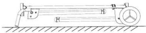
Line drawing of a tripod-mounted optical bench with a wheel and lever (no text or symbols)AJUSTE DE LOS SOPORTES DE MONTAJE DE LA SIERRA (FIG. M)
OPERACIÓN
Fig.
natural_image
Line drawing of a person walking with a long mechanical device attached (no text or symbols)Fig.
natural_image
Technical line drawing of a mechanical device with pulley and housing (no text or symbols)MANTENIMIENTO

ADVERTENCIA
natural_image
Technical line drawing of a mechanical assembly with no visible text or symbolsA
natural_image
Technical line drawing of two mechanical components with mounting holes and mounting brackets (no text or symbols)B
natural_image
Technical line drawing of a mechanical support bracket with two cylindrical components and three separate mounting holes (no text or symbols)C

natural_image
Technical line drawing of two parallel metal profiles with holes, no text or symbols presentD

natural_image
Technical line drawing of two mechanical components with bolts and brackets (no text or symbols)E


F

natural_image
Simple line drawing of a cylindrical rod or rod with two ends (no text or symbols)G

natural_image
Technical line drawing of mechanical parts including bolts, cylinders, and flanges (no text or symbols)H

natural_image
Collection of mechanical parts including screws, planks, and circular components arranged in two rows (no text or symbols)|

natural_image
Two identical metal loop components with mounting holes, shown in line drawing style (no text or symbols)J

INSTALAR OS BATENTES DO GRAMPO (FIG. D)
INSTALAR AS PLACAS DE ANCORAGEM (FIG. F, G)
natural_image
Line drawing of a tripod-mounted optical bench with a dial and lever (no text or symbols)INSTALAR A SERRA DE ESQUADRIA NO SUPORTE

AVISO
AJUSTAR OS GRAMPOS DE INSTALAÇÃO DA SERRA (FIG. M)
DOBRAR O SUPORTE (FIG. P, Q)

AVISO
Fig.
Q
Dobrar o suporte
flowchart
graph TD
    A["Start: L-shaped frame with weights"] --> B["Step 1: Rotation of pulley frame"]
    B --> C["Step 2: Rotation of weight"]
    C --> D["Step 3: Rotation of lifting weight"]
    D --> E["End: Close-up of frame"]
natural_image
Line drawing of a person walking with a long mechanical device attached (no text or symbols)Fig. S
natural_image
Technical line drawing of a mechanical device with pulleys and a wheel, no text or symbols presentMANUTENÇÃO

AVISO
natural_image
Technical line drawing of a mechanical support frame assembly (no text or symbols)A

natural_image
Technical line drawing of two mechanical components with mounting brackets and mounting holes (no text or symbols)B

natural_image
Technical line drawing of a mechanical support bracket with two cylindrical components and three separate mounting holes (no text or symbols)C

natural_image
Two parallel metal beams with circular holes, shown in isometric view (no text or symbols)D
natural_image
Technical line drawing of two mechanical components with bolts and brackets (no text or symbols)E


F

natural_image
Simple line drawing of a cylindrical rod or rod with two ends (no text or symbols)G

natural_image
Technical line drawing of mechanical components including bolts, cylinders, and flanges (no text or symbols)H

natural_image
Collection of mechanical parts including screws, platters, and diamonds arranged in a grid (no text or symbols)|

natural_image
Two identical metal loop components with mounting holes, shown in line drawing style (no text or symbols)J
PRODUKTSPECIFIKATIONER
C

MONTERA FÄSTESSTOPPARNA (BILD D)
MONTERA SÄGMONTERINGSFÄSTENA (BILD E)
MONTERA FÖRANKRINGSPLATTORNA (BILD F, G)
natural_image
Line drawing of a tripod-mounted optical bench with a wheel and lever (no text or symbols)MONTERA GERINGSSÅGEN PÅ STATIVET

WARNING
JUSTERA SÄGMONTERINGSFÄSTENA (BILD M)
ANVÄNDNING
ANVÄNDNINGSINSTRUKTIONER
WARNING
FÄLLA STATIVET (BILD P, Q)
WARNING
TRANSPORT OCH FÖRVARING (BILD R, S)
natural_image
Line drawing of a person pushing a long cylindrical device with wheels (no text or symbols)Bild
UNDERHÅLL

WARNING
natural_image
Technical line drawing of a mechanical support frame assembly (no text or symbols)A
natural_image
Technical line drawing of two mechanical components with mounting holes and mounting brackets (no text or symbols)B

natural_image
Technical line drawing of a mechanical support bracket with two cylindrical components and three separate mounting holes (no text or symbols)C

natural_image
Technical line drawing of two parallel metal profiles with holes and grooves (no text or symbols)D

natural_image
Technical line drawing of two mechanical components with bolts and brackets (no text or symbols)E


F

natural_image
Simple line drawing of a cylindrical rod or rod with two ends (no text or symbols)G

natural_image
Technical line drawing of mechanical components including bolts, cylinders, and flanges (no text or symbols)H

natural_image
Collection of mechanical parts including screws, diamonds, and circular components arranged in two rows (no text or symbols)|

natural_image
Two identical metal loop components with mounting holes, shown in line drawing style (no text or symbols)J
PRODUKTSPECIFIKATIONER
MONTERING AF BESLAGSSTOPPERE (FIG. D)
MONTERING AF SAVMONTERINGSBESLAGENE (FIG. E)
MONTERING AF ANKERPLADERNE (FIG. F, G)
natural_image
Line drawing of a tripod-mounted optical bench with a wheel and lever (no text or symbols)MONTERING AF GERINGSSAVEN TIL STATIVET

ADVARSEL
JUSTERING AF SAVMONTERINGSBESLAGENE (FIG. M)
Hvis savmonteringsbeslagene kan glide over de øverste skinner eller fjernes fra de øverste skinner, når beslagets kamlåse (1) er låst, skal beslagets justeringsskruer (2) strammes. Hvis savmonteringsbeslagene ikke passer over de øverste skinner, skal beslagets justeringsskruer løsnes.
FOLDNING AF STATIVET (FIG. P, Q)

ADVARSEL
Fig.
Q
flowchart
graph TD
    A["Foldning af stativet"] --> B["Person with no leg"]
    B --> C["Person in exercise position"]
    C --> D["Person in exercise position"]
TRANSPORT OG OPBEVARING (FIG. R, S)
natural_image
Line drawing of a person walking with a mechanical device attached (no text or symbols)Fig. S

natural_image
Technical line drawing of a mechanical device with pulleys and a wheel, no text or symbols presentVEDLIGEHOLDELSE

ADVARSEL
PAKK UT OG SJEKK INNHOLD
natural_image
Technical line drawing of a mechanical assembly with no visible text or symbolsA

natural_image
Technical line drawing of two mechanical components with mounting holes and mounting brackets (no text or symbols)B

natural_image
Technical line drawing of a mechanical support bracket with two cylindrical components and three separate mounting holes (no text or symbols)C

natural_image
Technical line drawing of two parallel metal profiles with holes and grooves (no text or symbols)D

natural_image
Technical line drawing of two mechanical components with bolts and brackets (no text or symbols)E


F

natural_image
Simple line drawing of a cylindrical rod or rod with two ends (no text or symbols)G

natural_image
Technical line drawing of mechanical components including bolts, cylinders, and flanges (no text or symbols)H

natural_image
Collection of mechanical parts including screws, diamonds, and circular components arranged in two rows (no text or symbols)|

natural_image
Two identical metal loop handles with mounting holes, shown in line drawing style (no text or symbols)J
PRODUKTSPESIFIKASJONER
BLI KJENT MED STATIVET DITT

MONTERING AV ANKERPLATENE (FIG. F, G)
natural_image
Line drawing of a bipod or tripod-mounted optical instrument with a circular dial and lever (no text or symbols)MONTERE GJÆRINGSSAG TIL STATIVET
⚠ ADVARSEL
JUSTERING AV SAGMONTERINGSBRAKETTENE (FIG. M)
BRUK
BRUKSINSTRUKSJONER

ADVARSEL
INNSTILLING AV STATIVET (FIG. N, O)
Fig. O
Sette opp stativet
BRETTE STATIVET (FIG. P, Q)

ADVARSEL
Fig.
Q
Brett sammen stativet
natural_image
Line drawing of a person pushing a long cylindrical device with wheels (no text or symbols)Fig. S

natural_image
Technical line drawing of a mechanical device with pulleys and a wheel, no text or symbols presentGENERELT VEDLIKEHOLD

ADVARSEL
GENERELT VEDLIKEHOLD
natural_image
Technical line drawing of a mechanical support frame assembly (no text or symbols)A

natural_image
Technical line drawing of two mechanical components with mounting brackets and mounting holes (no text or symbols)B
natural_image
Technical line drawing of a mechanical support bracket with two cylindrical components and three separate mounting holes (no text or symbols)C

natural_image
Two parallel metal beams with evenly spaced holes, shown in isometric view (no text or symbols)D

natural_image
Technical line drawing of two mechanical components with bolts and brackets (no text or symbols)E

F

natural_image
Simple line drawing of a cylindrical rod or rod with two ends (no text or symbols)G

natural_image
Technical line drawing of mechanical components including bolts, cylinders, and flanges (no text or symbols)H

natural_image
Collection of mechanical parts including screws, plates, and diamonds arranged in a grid (no text or symbols)|

natural_image
Two identical metal loop components with mounting holes, shown in line drawing style (no text or symbols)J
TUOTTEEN TEKNISET TIEDOT
KIINNIKKEEN PYSÄYTTIMIEN ASENTAMINEN (KUVA D)
ANKKURIPULTIN ALUSLAATAN ASENTAMINEN (KUVA F, G)
natural_image
Line drawing of a tripod-mounted optical bench with a wheel and lever (no text or symbols)JALUSTAN ASENTAMINEN JIIRISAHAAN

VAROITUS
ASENNUSKIINNIKKEIDEN SÄÄTÄMINEN (KUVA M)
KÄYTTÖ
KÄYTTÖOHJEET

VAROITUS
JALUSTAN KOKOON TAITTAMINEN (KUVA P, Q)

VAROITUS
KULJETUS JA VARASTOINTI (KUVA R, S)
natural_image
Line drawing of a person pushing a wheeled device with wheels (no text or symbols)Kuva
YLLÄPITO

VAROITUS
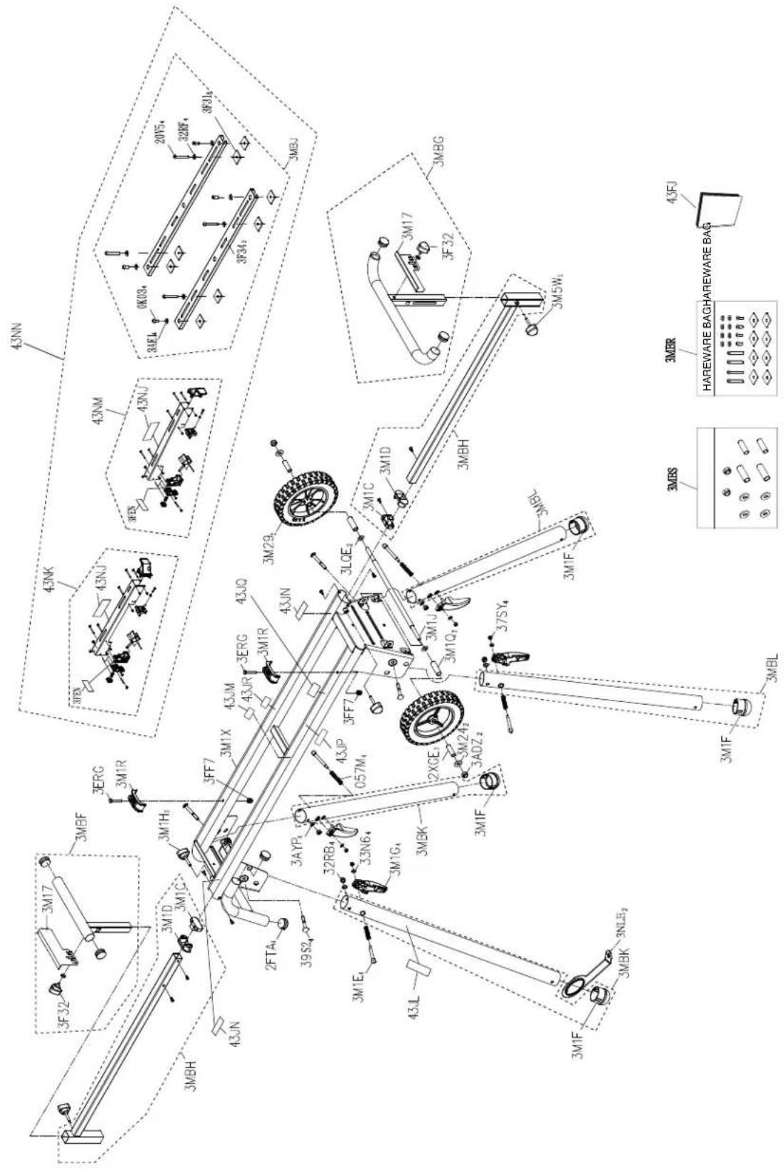
PARTS LIST Always order by I.D. NO. number
EPC No. I.D.No. Description Size Q'ty
| 339787 | 057M | SPRING | 4 | |||||
| 370335 | 0K03 | HEX. SOC. TRUSS HD. SCREW M8*1.25-15 4 | ||||||
| 339788 | 20V5 | HEX. SOC. TRUSS HD. SCREW M8*1.25-60 4 | ||||||
| 339789 | 2FTA | END | CAP | 4 | ||||
| 339790 | 2XGE | SLEEVE | 2 | |||||
| 339791 | 32RB | LOCK NUT | M8*1.25 T=8 | 4 | ||||
| 339792 | 32RF | FLAT | WASHER | 8*18-2 | 4 | |||
| 339793 | 33N6 | FLAT WASHER | 6*13-1.5 | 4 | ||||
| 339794 | 37SY | LOCK NUT | M6*1.0 T=6 4 | |||||
| 339795 | 39S2 | CAP HD. SQ. NECK BOLT | M8*1.25-65 4 | |||||
| 339796 | 3ADZ | LOCK NUT | M10*1.5 T=10 | 2 | ||||
| 339797 | 3AE1 | FLAT | WASHER | 8*28-2.5 | 4 | |||
| 339798 | 3AYP | FLAT | WASHER | 8.1*16-2 | 4 | |||
| 339800 | 3ERG | HEX. HD. BOLT | M6*1.0-40 | 2 | ||||
| 339801 | 3F31 | SQUARE | NUT | 8 | ||||
| 339802 | 3F32 | KNOB | 2 | |||||
| 339803 | 3F34 | RAIL | 2 | |||||
| 339866 | 3FEN | CAUTION | LABEL | 2 | ||||
| 339804 | 3FF7 | CROWN NUT | M6*1.0 T=13 | 2 | ||||
| 339805 | 3LQE | NYLON | WASHER | 10*20-2 | 2 | |||
| 339806 | 3M17 | FENCE | 2 | |||||
| 339807 | 3M1C | PLUG-BUTTON | 2 | |||||
| 339808 | 3M1D | PLUG-BUTTON | 2 | |||||
| 339809 | 3M1E | LOCATION | PIN | 4 | ||||
| 370546 | 3M1F | PLUG-BUTTON | 4 | |||||
| 339810 | 3M1G | PLUNGER | HANDLE | 4 | ||||
| 339811 | 3M1H | KNOB | 2 | |||||
| 339812 | 3M1J | LINK | BAR | 1 | ||||
| 339813 | 3M1Q | SLEEVE | 2 | |||||
| 339814 | 3M1R | GUIDE | CLAMP | 2 | ||||
| 339815 | 3M1X | TABLE | ASS'Y | 1 | ||||
| 339816 | 3M24 | FLAT | WASHER | 10*25-2 | 2 | |||
| 339817 | 3M29 | FLOOR WHEEL ASS'Y | 2 | |||||
| 339819 | 3M5W | KNOB | 2 | |||||
| 339820 | 3MBF | EXTENSION WING ASS'Y | 1 | |||||
| 339821 | 3MBG | EXTENSION WING ASS'Y | 1 | |||||
| 339822 | 3MBH | EXTENSION WING ASS'Y | 2 | |||||
| 339823 | 3MBJ | AUXILIARY MOUNTING BRACKET ASS'Y | 1 | |||||
| 339824 | 3MBK | SUPPORT | ASS'Y | 2 | ||||
| 339825 | 3MBL | SUPPORT | ASS'Y | 2 | ||||
| 339826 | 3MBR | AUXILIARY MOUNTING BARCKET HARDWARE BAG | 1 | |||||
| 339827 | 3MBS | WHEELS HARDWARE BAG | 1 | |||||
| 339828 | 3NLE | SET | PLATE | 2 | ||||
| 376213 | 43FJ | INSTRUCTION | MANUAL | 1 | ||||
| 376220 | 43JL | TRADEMARK | LABEL | 1 | ||||
| 376215 | 43JM | WARNING | LABEL | 1 | ||||
| 376211 | 43JN | WARNING | LABEL | 2 | ||||
| 376217 | 43JP | WARNING | LABEL | 1 | ||||
| 376218 | 43JQ | WARNING | LABEL | 1 | ||||
| 376219 | 43JR | WARNING | LABEL | 1 | ||||
| 376214 | 43NJ | TRADEMARK | LABEL | 2 | ||||
| 376210 | 43NK | PARALLEL BRACKET ASS'Y | 1 | |||||
| 376212 | 43NM | PARALLEL BRACKET ASS'Y | 1 | |||||
| 4100095 | 43NN | MOUNTING BRACKET ASS'Y | 1 |
MITER SAW STAND MODEL NO. UU 240F SCHEMATIC
Koki Holdings Co., Ltd.